

Page 1

1
USER MANUAL
MANUAL DE INSTRUCCIONES
NOTICE D'UTILISATION
BEDIENUNGSANLEITUNG
CA120HZ
Page 2

2
Page 3

3
INSTRUCTION MANUAL
1. IMPORTANT NOTE 04
1.1. Compliance with international standards 04
2. INTRODUCTION 04
3. INSTALLATION 05
3.1. Location and assembly 05
3.2. Mains connection 05
3.3. Audio input connections 05
3.4. Audio output connections 06
3.5. Remote control options 06
4. OPERATION AND USAGE 07
4.1. Operation and default mode 07
4.2. Special active source selection mode and setting adjust m ents 08
4.3. AUTO STANDBY Function 09
4.4. LED indicators 09
4.5. Micro switches on the rear panel 10
4.6. Lock mode 10
4.7. Restore default settings and update firmware 10
5. CLEANING 11
6. LIST OF FUNCTIONS 12
7. DIAGRAM OF FUNCTIONS 13
8. TECHNICAL CHARACTERISTICS 50
9. BLOCK DIAGRAM 51
10. CONFIGURATION DIAGRAM 52
All numbers subject to variation due to production tolerances. ECLER S.A. reserves the right to make changes or
improvements in manufacturing or design which may aff ec t specifications.
Page 4

4
1. IMPORTANT NOTE
Congratulations! You have acquired the r esult of painstaking design and manufacturing. Thank you
for having chosen our CA120HZ micro amplifier.
In order to get the optimum operation and efficiency from your product, it is VERY IMPORTANT before you plug anything - to read this manual very carefully and take seriously into account all
considerations specified within it.
We strongly recommend that its maintenance be carried out by our Authorised Technical Services.
1.1. Compliance with international standards
The CA120HZ micro amplifier complies with the following international standards:
• EN55103-1 Electromagnetic Compatibility.
Product family standard for audio, video, audio-visual and ent ertainment lighting control apparatus
for professional use
Part 1: Emission
• EN55103-2 Electromagnetic Compatibility.
Product family standard for audio, video, audio-visual and ent ertainment lighting control apparatus
for professional use
Part 2: Immunity
• EN60065 Audio, video and similar electronic apparatus. Safety requirements
Complying with the requirements of directives 73/23/EC and 2004/ 108/ EC
2. INTRODUCTION
The CA120HZ is a very small mono amplifier with high impedance output (70/100V) and a multitude
of remote control f unctions (RS-232 serial port, inf rared receiver, 0-10 VDC remote control port), and is
ideal for integrating audiovisual applications with other devices: educational classes, meeting rooms and
multimedia presentations, business premises, etc.
Main characteristics:
• 1 x 120 W RMS @ 70/100V amplifier
• Universal external power supply
• AUTO STANDBY function: in the absence of an audio signal the unit automatically goes into
STANDBY mode, minimising power consumption
• Lightweight, silent, high-performance amplifier (fan-free convection cooling)
• 1 switchable balanced mic / unbalanced line input, with high quality microphone preamplifier, phantom
power supply, noise gate and “talkover” function or priority over the rest of input
• 2 stereo lines (unbalanced)
• 2-band independent tone control (Bass, Treble) for the microphone / line 3 and line 1&2 input
connection.
• Auxiliary output for liaison with other amplifiers or external audio devices
• Local control by digital rotary knob (“encoder”)
• Remote control by infrared remote control
• Remote control by WPmVOL or WPmVOL-SR (0-10 VDC) wall panel
• RS-232 control port, compatible with EclerCOMM software (free) and control prot oc ol CA-NET
• MUTE port to silence the entire unit by closing external contact
Page 5

5
3. INSTALLATION
3.1. Location and assembly
The CA120HZ is suitable for installation on a wall or under a surface (t able, shelf, cupboard, etc.),
thanks to its design and layout of its connectors, controls and LED indicator lights.
3.2. Mains connection
The amplifier is powered by alternating current through its external power source: 100-240 VAC
and 50-60 Hz.
This apparatus must be earthed through its mains cable (earth resistance, Rg = 30Ω, or lower).
The environment should be as dry and dust f ree as possible. Do not expose the unit to rain or water
splashes. Do not place liquid containers or incandescent objects like candles on top of the unit.
Should any work or connection / disconnect ion task be done, always disconnect the unit f rom the
mains supply. There are no elements that can be manipulated by the user inside the amplifier.
To avoid buzzing, do not allow the power cable to intertwine with the shielded cables that
transport the audio signal.
3.3. Audio input connections
The CA120HZ accepts two types of signals in its input channels:
• Microphone (MIC): has a balanced Euroblock or jack type connection, ready to accept a
signal level between -20dBV y –50dBV, with adjustable sensitivity with the ADJ control
NOTE: the microphone input has a phantom power supply to power condenser
microphones, activated by internal bridge (see section 10. CONFIGURATION
DIAGRAM).
• Line signals (LINE1, LINE2, LINE3): they have unbalanced minijack or double RCA type
stereo connections. They are prepared for input of between -6dBV and 0dBV, with input
sensitivity that can be adjusted by internal port (see section 10. CONFIGURATION
DIAGRAM). You can connect signals from CD players, radio tuners, mixing consoles,
media players, the audio outputs of PCs and tablets, etc. to these connections.
NOTE: Turnt ables CANNOT BE CONNECTED directly to this device because none of the inputs
have an RIAA preamp.
The CA120HZ has the following operating modes according to the input sources selected as
active:
• LINE1: only the LINE1 input is sent to t he mix bus to be amplified and routed to t he OUTPUT in
mono format
• LINE2: only the LINE2 input is sent to t he mix bus to be amplified and routed to t he OUTPUT in
mono format
• LINE3/MIC: only the microphone (MIC) / line (LINE3) input is sent to the mix bus to be amplified
and routed to the OUTPUT in mono f or mat
• LINE1 + LINE3/MIC: the LINE1 and LINE3/MIC inputs are mixed, amplified and routed to the
OUTPUT in mono format. If the TALKOVER function is enabled, the LINE3/MIC input will
attenuate the LINE1 signal when the activation threshold is reached
• LINE2 + LINE3/MIC: the LINE2 and LINE3/MIC inputs are mixed, amplified and routed to the
OUTPUT in mono format. If the TALKOVER function is enabled, the LINE3/MIC input will
attenuate the LINE2 signal when the activation threshold is reached
Page 6

6
Select one of the 5 work modes in special selection mode with the rotat ing knob on the front ( see
section 4.2. Special selection mode of active sources and adjusting settings for details of the full
procedure).
3.4. Audio output connections
The amplified OUTPUT uses a Euroblock connector.
The connection cable between the CA120HZ output and the speak ers should be of good quality,
with a suitable cross section and as short as possible.
The output operates in mono mode only (L+R summed in case of active stereo input).
Additionally, the CA120HZ has an unamplified auxiliary output (AUX OUT) which makes it possible
to connect it to amplifiers or with other external devices. T he auxiliary output AUX OUT has a line level
signal (0dBV) which is an unamplified replica of the signal delivered to the OUTPUT terminals.
3.5. Remote control options
• REMOTE port: the RJ-45 REMOTE t ype connector allows the connection of a WPmVOL or
WPmVOL-SR (control 0-10 VDC) wall control panel to adjust the general output volume
and/or to select one of the f ive active work source modes (LINE1, LINE2, LINE3/MIC, LINE1
+ LINE3/MIC, LINE2 + LINE3/MIC). The connection is made by a standard CAT5 cable
between the WPmVOL or WPmVOL-SR wall panel and the REMOTE CA120HZ connector.
Because there is a CA120HZ W Pm type control as well as other types of controls (front
knob, infrared control and serial port control) the most recent adjustments by any of these
methods will prevail. For example, if an active source is selected and/or a volume adjustment
is made using the W PmVOL-Sr wall panel connected to the REMOTE port, and then these
settings are adjusted using t he front control, the adjustment made with the frontal control will
prevail. In this case, when the wall panel position is adjusted again, the CA120HZ will change
to the values indicated, and so on and so forth.
• MUTE por t: The MUTE connect or makes it possible to connect a power free contact to totally
silence the CA120HZ if an external device works on it (example: a emergencies and
centralised evacuation warning system).
• RS-232 port: the serial communication port RS-232 allows remote management of the
CA120HZ from a computer through the EclerCOMM software or CA-NET protocol from an
external control system supporting this protocol. See the CA-NET protocol manual for
detailed information on the connection and syntax of the commands supported. The
connection has the following specifications:
o Baud r at e: 9600 (fixed, without auto negotiation)
o Dat a bits : 8
o Par ity: None
o St op bits : 1
o Flow control: None
• Receiver IR: the built-in IR receiver gives general volume control of the CA120HZ and its
MUTE ON / OFF function from the REVO-IR remote control included with the unit.
WIRING RS-232 – DB9
RS-232 CA120HZ
DB9
Tx
Pin 2 (RxD)
Rx
Pin 3 (TxD)
Gnd
Pin 5 (Signal Gnd)
Page 7

7
4. OPERATION AND USAGE
4.1. Start up and default mode
Start up the CA120HZ by connecting the equipment to an external power source to which the DC
24V connector of the CA120HZ has already been connected. T he LED indicator ON/STBY immediately
lights up on the front panel. W e recommend you turn on all the devices in the following order: sound
sources, mixer, equalisers, active filters and processors and, finally power amplifiers. Powering off
should be done by following the exact reverse sequence. Following this order, the introduced noise due
to turning on or switching off the devices will not affect t hos e further on in the chain and will be inaudible.
The system defaults to volume adjustment mode. In this mode, the VOL/MUTE knob on the front
panel acts on the general output volume of the CA120HZ. This controller has a maximum of 64 steps
between the unit's minimum and m aximum volume. When turned, it will adjust the volume while the LED
LEVEL light is flashing. W hen the controller is turned to the left or to the right, this flashes while the
output volume increases or decreases. The light stops f lashing when it reaches either end of the scale
and it is no longer possible to increase or decrease the volume of t he unit .
Quickly press the VOL/MUTE controller to activate/deactivate the mute function of the unit
(MUTE ON/OFF). The MUTE LED lights when the mute function is activated.
If you adjust the volume using the infrared remote control, the LED LEVEL y MUTE visual
indicators are exactly the same as those seen when adjusting these with the knobs on the front panel.
Page 8
8
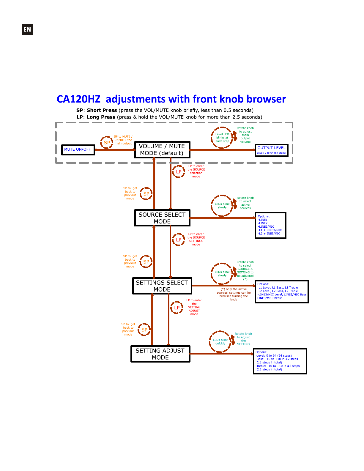
4.2. Special active source selection mode and sett ing adjustments
Use the knob on the front panel to access special modes f or selecting active sources and adjusting
levels and equalization (bass and treble). You can access these modes by holding in the knob for a certain
time and then turning it. By adjusting t he level of each source you can mix the signal fr om the microphone
or line (LINE3/MIC) and another line (LINE1 or LINE2), and the result of this mix will be controlled by the
general output volume of the unit together, in other words, respecting the relative levels set of each source.
The full procedure for acc essing and operating in t hese special modes and the options available in
each are set out in the following graph:
Notes:
1. If the device is in special mode for 10 seconds and the f ront knob is not touched, the equipment
automatically reverts to VOL/MUTE mode.
2. In tone control mode, when you turn the k nob in either direction it flashes fast while the gain of
the affected tone increases. When either end of the scale is reached ( -10 ó +10dB) or when it
goes through the centre point ( 0dB) it flashes more slowly.
Page 9

9
4.3. AUTO STANDBY Function
The AUTO STANDBY function (idle or low consumption mode) means you can install the
CA120HZ in inacces sible places and leave the device connected to the mains power supply permanently
because when no signal is detected, it automatically goes into standby mode, saving energy.
To enable AUTO STANDBY use the micro switch with the same name on the rear panel of the unit
(see section 7. DIAGRAM OF FUNCTIONS). When activated, if there is no audio signal in any of the
inputs (or the signal is very weak, below the activation threshold), the CA120HZ automatically goes into
STANDBY mode, and the ON/STBY on the front panel of the device goes orange. W hen a valid audio
signal is detected in any of the inputs, the CA120HZ leaves standby mode and starts operating normally
again and the ON/STBY LED goes green.
When you enable AUTO STANDBY m ode with the micro switch (position ON) one of two things
happens:
a) There is NO audio signal in the inputs. Result: the amplifier immediately goes into AUTO
STANDBY mode
b) There is an audio signal in the inputs. Result: the amplifier stays active
When the amplifier goes into AUTO STANDBY mode, all the LED indicators go out with the
exception of ON/STBY. If the amplifier is in STANDBY mode and you turn the VOL/MUTE knob to
adjust the volume or ac t ivate the MUTE function, the LED lights will come on for a shor t time then go out
again. Remember that t he first acting on the VOL/MUTE knob, this will only reset the LED indicators,
and will not change any of the settings.
When the unit is a special mode ( source selection or setting adjustm ent) the LED indicators will
not go out even if the amplifier is in AUTO STANDBY mode.
4.4. LED indicators
• SP: The signal presence or SP LED indicator shows that there is a signal in the amplifier
input. This lights up when the input level reaches the established detection thres hold.
• CLIP: The saturation or CLlP LED indicator comes on when the signal delivered to the
speakers is close to the amplifier's clipping or saturation level. Input signals should be set to
ensure the CLIP (saturation or cut of f ) indicator s never stay on, but t hat t hey do so at m ost t o
the beat of the lowest sound frequencies. Otherwise the amplif ied signal will be distorted with
low quality and low intelligibility.
Note: If the input signal is too high, the CLIP indicator lighting up very frequently over a
short time interval (a few seconds), t he am plifier may go into protection mode, being m ut ed to
return to normal operation in a short tim e
• MUTE: This lights up when the MUTE function is active (silent mode)
• ON/STBY: the green light com es on when the equipment is in normal operating mode and it
goes orange when it is in standby or low consumption mode (STANDBY).
• LEVEL: This flashes when you adjust the general level of the device. It also lights up during
special adjustment modes, input levels (see section 4.2. Special active source selection
mode and setting adjustments)
• BASS: This light up during special adjustment modes bass frequencies (see section 4.2.
Special active source selection mode and setting adjustm ent s)
• TREBLE: This light up during special adjustment modes, trebl e frequencies ( see section 4.2.
Special active source selection mode and setting adjustm ent s)
• LINE1, LINE2, LINE3/MIC: These lig hts up during special modes, selection of active sources
and adjustments (see section 4.2. Special active source selection mode and setting
adjustments)
Page 10

10
4.5. Micro switches on the rear panel
• REMOTE: Turn on (ON) the remote control from the WPmVOL or WPmVOL-SR wall panel
connected to the REMOTE port.
• NOISE GATE: Turn on (ON) or turn off the noise gate func tion for the LINE3/MIC input. When
this function is active the microphone input is muted whilst there is no signal above the function
activation threshold, so the equipment rej ects background noise captured by the microphone
connected to it.
• TALKOVER: On or off according to the priority of the LINE3/MIC input over the line inputs
(LINE1 or LINE2). W hen the TALKOVER function is on, the LINE3/MIC signal will attenuate
the selected line (LINE 1 or 2) when the activation threshold set is r eac hed.
• AUTO STANDBY: Switch the AUTO STANDBY function on (O N) or off. W hen the func tion is
on, the CA120HZ will automatically go into STANDBY or low consumption mode in the
absence of audio signals in its inputs.
• LINE3/MIC: input selection between LINE and MIC3 (line level input from RCA connectors or
microphone level input from Euroblock connector)
• HPF: frequency selection (50 or 70 Hz) for the unit's high-pass filter
4.6. Lock mode
To switch the CA120HZ lock mode on or off hold in the VOL/MUTE control for 10 s econds from the
VOL/MUTE mode. The LED SETTING indicators will flash 3 times to indicate that lock mode is now on.
When in lock mode the device cannot be managed using the VOL/MUTE contr ol (it will flash t hr ee t im es to
show that it is in that mode when you turn the knob). This will protect the equipment from unwanted
handling until it is restored to normal operation after holding the VOL/MUTE control in for a further 10
seconds (the LED SETTING indicators will flash twice to show that the lock mode is off).
Note: once lock mode is activated it will stay activated even when the equipment is turned off and
on again. It will stay in lock mode until the VOL/MUTE control is held in for 10 seconds again.
4.7. Restore default settings and update firmware
If you would like to restore the CA120HZ to factory settings, follow this procedure:
1. Unplug the equipment then press and hold the knob in.
2. Plug back the unit without releasing the knob. The MUTE LED indicator will flash.
3. Wait a few seconds and then switch the CA120HZ off again.
4. The next time you turn it on, the factory settings will be in the memory.
Note: for instruct ions on how to update the unit's firmware, see the product web page at
www.ecler.com,
where you will find the update software utility and instructions on how to proceed.
Page 11

11
5. CLEANING
The CA120HZ must not be cleaned with solvents or abrasive substances which may damage t he
prints. Clean using a cloth moistened in water and a neutral liquid deter gent, then dry with a clean cloth.
Under no circumstances allow water to enter any of the orifices in the equipment.
Page 12

12
6. LIST OF FUNCTIONS
1. LEVEL indicator light
2. BASS indicator light
3. TREBLE indicator light
4. LINE1 indicator light
5. LINE2 indicator light
6. MIC indicator light
7. VOL/MUTE knob
8. SP input signal presence indicator light
9. CLIP indicator light
10. MUTE indicator light
11. ON/STBY on or standby indicator light
12. REMOTE, remote control receiver
13. HPF micro switch
14. MIC/LINE3 micro switch
15. AUTO STANDBY micro switch
16. TALKOVER micro switch
17. NOISE GATE micro switch
18. REMOTE micro switch
19. Remote control by protocol CA-NET, RS-232
20. RJ-45, REMOTE connector
21. MUTE remote control
22. DC24V power connector
23. OUTPUT amplified output
24. AUX OUT
25. RCA input line, LINE1
26. Mini jack input line, LINE2
27. RCA input line, LINE3
28. Microphone input, MIC
29. Microphone jack, MIC
30. MIC input sensitivity setting
31. Volume down key
32. Volume up key
33. Mute key
Page 13

13
7. DIAGRAM OF FUNCTIONS
Page 14

14
Page 15

15
MANUAL DE INSTRUCCIONES
1. NOTA IMPORTANTE 16
1.1. Conformidad con normativas internacionales 16
2. INTRODUCCIÓN 16
3. INSTALA C IÓN 17
3.1. Ubicación y montaje 17
3.2. Conexión a red eléctrica 17
3.3. Conexiones de audio de entrada 17
3.4. Conexiones de audio de salida 18
3.5. Opciones de control remoto 18
4. OPERACIÓN Y USO 19
4.1. Puesta en funcionamiento y modo por defecto 19
4.2. Modos especiales de selección de fuentes activas
y ajuste de sus parámetros 20
4.3. Función AUTO STANDBY 21
4.4. Indicadores LED 21
4.5. Microinterruptores del panel posterior 22
4.6. Modo de bloqueo 22
4.7. Restaurar valores por defecto y actualización de firmware 22
5. LIMPIEZA 23
6. LISTA DE FUNCIONES 24
7. DIAGRAMA DE FUNCIONES 25
8. CARACTERÍSTICAS TÉCNICAS 50
9. DIAGRAMA DE BLOQUES 51
10. DIAGRAMA DE CONFIGURACIÓN 52
Todos los datos están sujetos a variación debida a tolerancias de producción. ECLER S.A. se reserva el derecho de
realizar cambios o mejoras en l a fabricación o diseño que pudieran afectar l as especificaciones.
Page 16

16
1. NOTA IMPORTANTE
¡Enhorabuena!. Vd. posee el resultado de un cuidadoso diseño y una esmerada fabricación.
Agradecemos su confianza por haber elegido nuestro micro amplificador CA120HZ.
Para conseguir la máxima operatividad del aparato y su máximo rendimiento es MUY
IMPORTANTE, antes de su conexión, leer detenidamente y tener m uy presentes las consideraciones que
se especifican en este manual.
Para garantizar el óptimo funcionamiento de est e aparato, recomendamos que su mantenimiento
sea llevado a cabo por nuestros Servicios Técnicos autorizados.
1.1. Conformidad con normativas internacionales
El micro amplificador CA120HZ está conforme a las siguientes normativas internacionales:
• EN55103-1 Compatibilidad Electromagnética.
Norma de familia de Productos para aparatos de uso profesional de sonido, vídeo, sistemas
audiovisuales y para el control de iluminación para espectáculos
Parte 1: Emisión
• EN55103-2 Compatibilidad Electromagnética.
Norma de familia de Productos para aparatos de uso profesional de sonido, vídeo, sistemas
audiovisuales y para el control de iluminación para espectáculos
Parte 2: Inmunidad
• EN60065 Aparatos de audio, vídeo y aparatos análogos. Requisitos de seguridad
Cumpliendo los requisitos de las directrices 73/23/CEE y 2004/108/CE
2. INTRODUCCIÓN
El CA120HZ es un amplificador mono con salida en alta impedancia (70/100V) de muy reducido
tamaño y multitud de funciones de control remoto (puerto serie RS-232, r eceptor de infr arrojos, puer to de
control remoto 0-10 VDC), siendo una opción ideal en aplicaciones de integración audiovisual con otros
dispositivos: clases de enseñanza, salas de reuniones y presentaciones multimedia, locales comerciales,
etc.
Características principales:
• Amplificador de 1 x 120 W RMS @ 70/100V
• Fuente de alimentación externa universal
• Función AUTO STANDBY: en caso de ausencia de señal de audio la unidad pasa automáticament e al
modo de reposo o STANDBY, quedando su consumo minimizado
• Amplificador de alto rendimiento ligero y silencioso (refrigeración por convección, sin ventilador)
• 1 entrada conmutable de micrófono balanceada / línea no balanceada, con preamplificador de
micrófono alta calidad, aliment ación Phantom, puerta de ruido y función de “talkover” o prioridad sobre
el resto de entradas
• 2 entradas de línea estéreo (no balanceadas)
• Control de tonos de 2 bandas ( Bass, Treble) independiente para la entrada de micrófono / línea y la
entrada 1&2 de línea
• Salida auxiliar para enlace con otros amplificadores o dispositivos de audio externos
• Control local mediante control giratorio digital (“encoder”)
• Control remoto mediante mando a distancia por infrarrojos
• Control remoto mediante panel mural WPmVOL o WPmVOL-SR (0-10 VDC)
• Puerto de control RS-232, compatible con el software EclerCOMM (gratuito) y con el protocolo de
control CA-NET
• Puerto MUTE para silenciamiento total de la unidad mediante cierre de contacto externo
Page 17

17
3. INSTALA C IÓN
3.1. Ubicación y montaje
El CA120HZ admite instalación en pared o bien sobre o bajo una superficie (mesa, estantería,
mueble, etc.), gracias a su diseño y a la disposición de sus conectores, controles e indicadores LED.
3.2. Conexión a red eléctrica
El amplificador se alimenta con corr iente alterna mediante su f uente de aliment ación externa: 100240 VAC y 50-60 Hz.
La fuente de alimentación del amplificador debe conectarse a una toma de tierr a en condiciones
(resistencia de tierra, Rg = 30Ω, o m enor). El ambiente de trabajo deberá ser seco y estar totalmente
libre de polvo. No exponga el aparato a la caída de agua o salpicaduras. No ponga encima objetos con
líquido ni fuentes de llama desnuda, como velas.
En caso de requerir alguna intervención y/o conexión-desconexión del amplificador debe
desconectarse previamente la alimentación. En el interior del amplificador no existen elementos
manipulables por el usuario.
Debe evitarse que el cable de red se entremezcle con los cables blindados que transport an la señal de
audio, ya que ello podría ocasionar zumbidos.
3.3. Conexiones de audio de entrada
El CA120HZ admite dos tipos de señales en sus canales de entrada:
• Micrófono (MIC): dispone de conexión balanceada tipo Euroblock o jack, preparada par a
admitir un nivel de señal entre -20dBV y –50dBV, con sensibilidad ajustable mediante su
control ADJ
NOTA: la entrada de micrófono dispone de alimentación Phantom para alimentar
micrófonos de condensador, activable mediante puente interno (ver sección 10.
DIAGRAMA DE CONFIGURACIÓN).
• Señales de línea (LINE1, LINE2, LINE3): disponen de conexión estéreo no balanceada
tipo minijack o doble RCA. Están prepar adas para admitir señales entre -6dBV y 0dBV,
con sensibilidad ajustable mediante puente interno (ver sección 10. DIAGRAMA DE
CONFIGURACIÓN). Es posible conectar a ellas señales de reproductores de CD,
sintonizadores de radio, consolas de mezcla, reproductores multimedia, salidas de audio de
ordenadores y tablets, etc.
NOTA: NO PUEDEN CONECTARSE directamente a este aparato platos giradiscos ya que
ninguna de las entradas dispone de preamplificador tipo RIAA.
El CA120HZ permite los siguientes modos de trabajo, en función de qué fuentes de entrada
sean seleccionadas como activas:
• LINE1: sólo la entr ada LINE1 es enviada al bus de mezcla para ser amplificada y entregada en
la salida OUTPUT en formato mono
• LINE2: sólo la entr ada LINE2 es enviada al bus de mezcla para ser amplificada y entregada en
la salida OUTPUT en formato mono
• LINE3/MIC: sólo la entrada de micrófono ( MIC) / línea (LINE3) es enviada al bus de mezcla para
ser amplificada y entregada en la salida OUTPUT en formato mono
• LINE1 + LINE3/MIC: las entradas LINE1 y LINE3/MIC son mezcladas, amplificadas y
entregadas en la salida OUTPUT en formato mono. Si la función TALKOVER se encuentra
activa, la LINE3/MIC atenuará a la de LINE1 al superar el umbral de activación
• LINE2 + LINE3/MIC: las entradas LINE2 y LINE3/MIC son mezcladas, amplificadas y
entregadas en la salida OUTPUT en formato mono. Si la función TALKOVER se encuentra
activa, la LINE3/MIC atenuará a la de LINE2 al superar el umbral de activación
Page 18

18
La selección de uno de los 5 modos de trabajo se realiza mediante el modo especial de
selección del control giratorio frontal (ver sección 4.2. Modos de selección de fuentes activas y
ajuste de sus parámetros para conocer el procedimiento complet o) .
3.4. Conexiones de audio de salida
La salida amplificada OUTPUT está provista de conector Euroblock.
El cable de conexión que une la salida del CA120HZ y los altavoces, deberá ser de buena calidad,
de suficiente sección y lo más corto posible.
La salida funciona únicamente en modo mono (misma señal, suma L+R cuando exista entrada
estéreo activa).
Adicionalmente, el CA120HZ dispone de una salida auxiliar (AUX OUT) no amplificada, que
permite enlazarlo con amplificadores u otros dispositivos externos. La salida auxiliar AUX OUT
proporciona una señal de nivel de línea (0dBV) que es una réplica sin amplificar de la señal entregada en
los terminales OUTPUT.
3.5. Opciones de control remoto
• Puerto REMOTE: el conector tipo RJ-45 REMOTE permite la conexión de un panel de
control mural tipo W PmVOL o WPmVOL-SR (contr ol 0-10 VDC) para el ajuste del volumen
general de salida y/o la selección de uno de los 5 modos de fuentes activas de trabajo
(LINE1, LINE2, LINE3/MIC, LINE1 + LINE3/MIC, LINE2 + LINE3/MIC). El conexionado se
realiza mediante un cable CAT5 estándar entre el panel mural W PmVOL o W PmVOL-SR y
el conector REMOTE del CA120HZ.
Al coexistir en un CA120HZ un control tipo WPm con otros tipos de control (control
giratorio frontal, mando de infrarrojos o control vía puerto serie) prevalecerán siempre los
últimos ajustes realizados por uno u otro método. Por ejem plo, si se realiza una selección de
fuentes activas y/o un ajuste de volumen mediante un panel mural W PmVOL-SR conect ado
al puerto REMOTE, y a continuación se modifican dichos parámetros mediante el control
frontal, prevalecerá el ajuste realizado mediante dicho contr ol frontal. En este caso, cuando
se vuelva a modificar la posición del panel mural, el CA120HZ ret omará los valores que éste
le indique, y así sucesivamente.
• Puerto MUTE: el conec tor MUTE permite la conexión de un cierre de cont acto externo libre
de potencial para silenciar totalmente el CA120HZ en caso de que un dispositivo externo
actúe sobre él (ejemplo: un sistema de avisos para emergencias y evacuación centralizado).
• Puerto RS-232: el puerto de comunicación serie RS-232 permite la gestión remota del
CA120HZ desde un ordenador mediante el software EclerCOMM o el protocolo CA-NET
desde un sistema de control externo que soporte dicho protocolo. Vea el manual del
protocolo CA-NET para obtener información completa acer ca de los detalles de la conexión y
la sintaxis de los comandos soportados. Las especificaciones de la conexión serie son las
siguientes:
o Baud r at e: 9600 (fijo, sin autonegociación)
o Dat a bits : 8
o Par ity: None
o St op bits : 1
o Flow control: None
• Receptor IR: el receptor IR integrado permite el cont rol del volumen general del CA120HZ y
de su función de MUTE ON / OFF desde el mando a distancia REVO-IR incluido con la
unidad.
CABLEADO RS-232 – DB9
RS-232 CA120HZ
DB9
Tx
Pin 2 (RxD)
Rx
Pin 3 (TxD)
Gnd
Pin 5 (Signal Gnd)
Page 19

19
4. OPERACIÓN Y USO
4.1. Puesta en funcionamiento y modo por defecto
El encendido del CA120HZ se realizará mediante la conexión a la red de la fuente de
alimentación externa previamente conectada al conector DC 24V del CA120HZ. Inmediatamente se
iluminará el indicador LED ON/STBY del panel frontal. Es muy recomendable poner en m archa todos
los aparatos siguiendo la secuencia siguiente: fuentes de sonido, unidad de mezclas, ecualizadores,
filtros activos y procesadores y, finalmente, amplificadores de potencia. El apagado de los aparatos
debe realizarse en la secuencia inversa. Siguiendo este orden los transitorios producidos por el
encendido o apagado de los aparatos no afectarán a los siguientes en la cadena, permaneciendo
inaudibles.
Por defecto, la unidad se encontrará en el modo de ajust e de volumen. En este modo el control
giratorio VOL/MUTE del panel frontal actúa sobre el volumen general de salida del CA120HZ. Este
control dispone de un máximo de 64 pasos entre el volumen mínimo y el máximo de la unidad. Al girarlo
se modificará dicho volumen mientras parpadea el indicador LED LEVEL. Al girar el control en uno u
otro sentido, éste parpadea mientras se aument a o reduce el volumen de salida, quedando iluminado
fijo cuando se llega a uno de ambos extremos y no es posible aumentar o reducir más el volumen de la
unidad.
Si se pulsa brevemente el control VOL/MUTE se actúa sobre la activación / desactivación de la
función de enmudecimiento de la unidad (MUTE ON/OFF), iluminándose el indicador LED MUTE
cuando se halle activo el enmudecimiento.
Si se realiza un ajuste de volumen mediante el mando a distancia por infrarrojos las indicaciones
visuales mediante los LEDs LEVEL y MUTE son exactamente las mismas que para el ajuste mediante
el control giratorio del panel frontal.
Page 20

20
4.2. Modos especiales de selección de fuentes act i vas y ajuste de sus parámetros
Mediante el control giratorio frontal es posible entrar en modos especiales para la selección de las
fuentes activas y el ajuste de sus parámetros de nivel y ecualización (graves y agudos). La entrada y
navegación en dichos modos se realiza mediante pulsaciones de determinada duración del control
giratorio y su posterior giro. El ajuste de nivel de cada fuente perm ite realizar una mezcla entre una señal
de micrófono o línea (LINE3/MIC) y otra de línea (LINE1 o LINE2) y que el resultado de dicha mezcla sea
afectado por el volumen general de salida de la unidad de manera conjunta, es decir, respetando los
niveles relativos establecidos para cada fuente.
El procedimiento completo para entrar y operar en est os modos especiales, así como las opciones
disponibles en cada uno de ellos, se encuentran reflejados en el gráfico siguiente:
Notas:
1. Si, estando en cualquier modo especial, transcurren 10 segundos sin actuar sobre el control
giratorio frontal, se retornará automáticamente al modo por defecto de ajuste de VOL/MUTE.
2. En el modo de ajuste de tonos, al girar el control en uno u otro sentido, éste parpadea
rápidamente mientras se aumenta la ganancia del tono af ectado, parpadeando más lentamente
al llegar a uno de los extremos (-10 ó +10dB) o bien al pasar por el punto centr al ( 0dB) .
Page 21

21
4.3. Función AUTO STA N DB Y
La funcionalidad AUTO STANDBY (modo de reposo o bajo consumo) proporciona la posibilidad de
instalar el CA120HZ en lugares poc o accesibles, dado que permite dejar el aparato conectado a la red
eléctrica de forma permanente, activándose o desactivándose este modo de forma automática según
haya presencia de señal de entrada o no.
Para habilitar el modo AUTO STANDBY es preciso actuar sobre el microinterruptor del mismo
nombre ubicado en el panel posterior de la unidad (ver sección 7. DI AGRAMA DE FUNCIONES). Cuando
se encuentre habilitado y no exista señal de audio durante 2 minutos o más en cualquiera de las entradas
del aparato (o sea muy débil, inferior al umbral de activación), el CA120HZ pasará automáticamente a
modo STANDBY, encendiéndose en naranja el indicador LED ON/STBY ubicado en el panel frontal del
dispositivo. Al reaparecer una señal de audio válida en cualquiera de las entradas, el CA120HZ despertará
del modo de reposo y volverá al régimen normal de funcionamiento, retornando el indicador LED
ON/STBY a su condición encendido en color verde.
Al habilitar el modo AUTO STANDBY con el micr ointerruptor (posición ON) puede ocurrir uno de
los siguientes 2 supuestos:
a) NO hay señal de audio en las entradas. Resultado: el amplificador entra en AUTO STANDBY
inmediatamente
b) SÍ hay señal de audio en las entradas. Resultado: el amplificador continúa activo
Cuando el amplificador entra en modo AUTO STANDBY se apag an todos los indicadores LED,
excepto el de ON/STBY. Si, estando en modo STANDBY, se actúa sobr e el control giratorio VOL/MUTE
para cambiar de volumen o activar la función MUTE, se restablecen los indicadores LED durante un
tiempo corto, para luego volverse a apagar. Hay que tener en cuenta que el primer movimiento del
control giratorio VOL/MUTE únicamente restablecerá los indicadores LED, no actuando sobre ningún
parámetro hasta los siguientes movimientos.
Cuando la unidad se encuentra en alguno de los modos especiales (selección de fuentes,
selección de parámetros o ajuste de parámetros) los indicadores LED no se apagan aunque el
amplificador entre en el modo AUTO STANDBY.
4.4. Indicadores LED
• SP: El indicador LED de presencia de señal o SP advierte de la presencia de señal en la
entrada del amplificador. Se enciende cuando el nivel en la entrada supera el umbral de
detección establecido.
• CLIP: El indicador LED de saturación o CLlP se ilumina cuando la señal entregada a los
altavoces se halla cercana al nivel de recorte o saturación del amplif icador. Deben ajustarse
los niveles de señal entrante de manera que nunca queden permanentem ente encendidos
los indicadores CLIP (saturación o r ecorte), sino q ue lo hagan como máximo al ritmo de las
frecuencias más graves del pasaje sonor o. De lo contrario la señal amplificada presentaría
altos niveles de distorsión y una baja calidad acústica e inteligibilidad.
Nota: si la señal de entrada es excesivamente alta, iluminándose el indicador CLIP muy
frecuentemente durante un intervalo de tiempo corto (pocos segundos), el amplificador
podría entrar en modo de protección, silenciándose para retornar al modo normal de
funcionamiento en breves instantes
• MUTE: se ilumina cuando la función MUTE se encuentra activa (equipo silenciado)
• ON/STBY: se ilumina en verde cuando el equipo se encuentra en su régimen normal de
funcionamiento y en naranja cuando se encuentra en el modo de reposo o bajo consumo
(STANDBY).
Page 22

22
• LEVEL: parpadea al ajustar el nivel general del equipo. También se ilumina durante los
modos especiales de ajuste, nivel de entradas (ver sección 4.2. Modos de selección de
fuentes activas y ajuste de sus parámetros)
• BASS: se ilumina durante los modos especiales de ajuste, f recuencias graves (ver sección
4.2. Modos de selección de fuentes activas y ajuste de sus parámetros)
• TREBLE: se ilumina durante los modos especiales de ajuste, frecuencias agudas (ver
sección 4.2. Modos de selección de fuentes acti vas y ajuste de sus parámetros)
• LINE1, LINE2, LINE3/MIC: se iluminan dur ante los modos especiales, selección de fuentes
activas y ajustes (ver sección 4.2. Modos de selección de fuentes acti vas y ajuste de sus
parámetros)
4.5. Microinterruptores del panel posterior
• REMOTE: habilita (ON) el control rem ot o desde un panel mural tipo WPmVOL o WPmVOL-SR
conectado al puerto REMOTE.
• NOISE GATE: activa (ON) o desactiva la función de puerta de ruido para la entrada
LINE3/MIC. Cuando dicha función se encuentra activada la entrada de micro se encuentra
silenciada mientras no exista una señal superior al umbral de activación de la función,
rechazando de esta forma el ruido de fondo captado por el micrófono conectado a ella.
• TALKOVER: activa (ON) o desactiva la función de prioridad de la entrada LINE3/MIC sobre
las entradas de línea (LI NE1 o LINE2). Cuando la función TALKOVER se encuentra activa,
la señal LINE3/MIC atenuará a la de línea que se encuentre seleccionada (LI NE 1 ó 2) al
superar el umbral de activación definido.
• AUTO STANDBY: activa (ON) o desactiva la función de AUTO STANDBY. Cuando dicha
función se encuentra activa el CA120HZ pasará automáticamente al modo STANDBY o de
bajo consumo en ausencia de señales de audio en sus entradas.
• LINE3/MIC: selección de entrada LINE3 o MIC (entrada de nivel de línea desde conectores
RCA o entrada de nivel de micrófono desde conector Euroblock)
• HPF: selección de la frecuencia para el filtro paso-altos de la unidad, 50 o 70 Hz
4.6. Modo de bloqueo
Para entrar o salir del modo de bloqueo del CA120HZ es preciso mantener pulsado el control
VOL/MUTE durante un período de 10 segundos, desde el modo VOL/MUTE. Los indicadores LED
SETTING parpadearán 3 veces para indicar la entrada en el modo de bloqueo. En el modo de bloqueo no
es posible manejar el dispositivo mediante el control VOL/MUTE (volverá a parpadear 3 veces para indicar
que se encuentra en dicho modo al operar sobre el control giratorio) , quedando este protegido frente a
manipulaciones indebidas hasta que se retorne al funcionamiento normal del equipo tras mantener
pulsado de nuevo el control VOL/MUTE durante un período de 10 segundos (los indicadores LED
SETTING parpadearán 2 veces para indicar la salida del modo de bloqueo).
Nota: el modo de bloqueo, una vez activado, se mantiene incluso después de apagar y encender el
equipo, no saliendo de él hasta que se actúa de nuevo pulsando y manteniendo pulsado de nuevo el
control VOL/MUTE durante un período de 10 segundos
4.7. Restaurar valores por defecto y actualización de firmware
Si desea restaurar los ajustes de fábrica del CA120HZ siga este procedimiento:
1. Con el equipo apagado, pulse y mantenga pulsado el control giratorio
2. Sin soltarlo, encienda la unidad. El indicador LED MUTE parpadeará
3. Espere unos segundos y apague de nuevo el CA120HZ
4. La próxima vez que lo encienda, tendrá en memoria los ajustes por def ecto con los que la unidad
sale de fábrica
Nota: para actualizar el f irmware de la unidad, consulte la página de producto en
www.ecler.com, donde
hallará la utilidad software de actualización y las instrucciones para llevar a cabo el proceso.
Page 23

23
5. LIMPIEZA
El CA120HZ no deberá limpiarse con sustancias disolventes o abrasivas puesto que se corre el
riesgo de deteriorar la serigrafía. Para su limpieza se utilizará un trapo humedecido con agua y un
detergente líquido neutro, secándolo a continuación con un paño limpio. En ningún caso s e debe permitir
la entrada de agua por cualquiera de los orificios del aparato.
Page 24

24
6. LISTA DE FUNCIONES
1. Indicador luminoso LEVEL
2. Indicador luminoso BASS
3. Indicador luminoso TREBLE
4. Indicador luminoso LINE1
5. Indicador luminoso LINE2
6. Indicador luminoso MIC
7. Control giratorio digital VOL/MUTE
8. Indicador luminoso de presencia de señal en la entrada SP
9. Indicador luminoso de recorte CLIP
10. Indicador luminoso de enmudecimiento MUTE
11. Indicador luminoso de funcionamiento/reposo O N/ STBY
12. Receptor del mando a distancia, REMOTE
13. Microinterruptor, HPF
14. Microinterruptor, LINE3/MIC
15. Microinterruptor AUTO STANDBY
16. Microinterruptor TALKOVER
17. Microinterruptor NOISE GATE
18. Microinterruptor REMOTE
19. Control remoto mediante protocolo CA-NET, RS-232
20. Conector RJ-45, REMOTE
21. Control remoto MUTE
22. Conector de alimentación DC24V
23. Salida amplificada OUTPUT
24. Salida auxiliar AUX OUT
25. Entrada línea RCA, LINE1
26. Entrada línea minijack, LINE2
27. Entrada línea RCA, LINE3
28. Entrada de micrófono, MIC
29. Entrada de micrófono jack , MIC
30. Ajuste de sensibilidad entrada MIC
31. Pulsador para bajar el volumen
32. Pulsador para subir el volumen
33. Pulsador de enmudecimiento de equipo
Page 25

25
7. DIAGRAMA DE FUNCIONES
Page 26

26
Page 27

27
NOTICE D’INSTRUCTIONS
1. NOTE IMPORTANTE 28
1.1. Conformité avec les réglementations internationales 28
2. INTRODUCTION 28
3. INSTALLATION 29
3.1. Emplacement d'installation et montage 29
3.2. Raccordement au secteur 29
3.3. Branchement de l'entrée audio 29
3.4. Branchement de la sortie audio 30
3.5. Options de commande à distance 30
4. FONCTIONNEMENT ET U TILISA TION 31
4.1. Mise en marche et mode de fonctionnement par défaut 31
4.2. Modes spéciaux de sélection de sources actives et
réglage de leurs paramètres 32
4.3. Fonction AUTO STANDBY 33
4.4. Voyants DEL 33
4.5. Micro-interrupteurs du panneau arrière 34
4.6. Mode de verrouillage 34
4.7. Restauration des valeurs par défaut et mise à jour du
micrologiciel 35
5. ENTRETIEN 35
6. LISTE DES FONCTIONS 36
7. SCHÉMA DE FONCTIONS 37
8. CARACTÉRISTIQUES TECHNIQUES 50
9. SCHÉMA FONCTIONNEL 51
10. SCHÉMA DE CONFIGURATION 52
Toutes les valeurs numériques sont soumises à variation, en raison des toléranc es de production. ECLER S.A. se réserve le
droit d'apporter des modifications ou améliorations en matière de fabrication ou de design, susceptibles d'affecter les
spécifications du produit.
Page 28

28
1. NOTE IMPORTANTE
Félicitations ! Vous avez en votre possession le résultat d’une conception et d’une fabrication
particulièrement soignées. Nous vous remercions de votre confiance pour avoir choisi notre microamplificateur CA120HZ.
Pour exploiter au mieux toutes les f onctionnalités et obtenir un r endement m aximal de cet appareil,
il s'avère TRÈS IMPORTANT de lire attentivement et de suivre les recom mandations de ce manuel avant
toute connexion.
Pour obtenir le meilleur fonctionnement de cet appar eil, il est préconisé que l’entretien soit réalisé
par le Service technique Ecler.
1.1. Conformité avec les réglementations internationales
Le micro-amplificateur CA120HZ est conforme aux réglementations internationales suivantes :
• EN55103-1 Compatibilité électromagnétique.
Norme de famille de produits pour les appareils à usage professionnel audio, vidéo,
audiovisuels et de commande de lumière pour spectacles
Partie 1 : émissions
• EN55103-2 Compatibilité électromagnétique.
Norme de famille de produits pour les appareils à usage professionnel audio, vidéo,
audiovisuels et de commande de lumière pour spectacles
Partie 2 : immunité
• EN60065 Appareils audio, vidéo et appareils électroniques analogues. Exigences de sécurité
Respect des exigences des directives 73/23/CEE et 2004/108/CE
2. INTRODUCTION
Le CA120HZ est un amplificateur mono à sortie haut e impédance (70/100 V), de très petite t aille et
avec une multitude de fonctions de commande à distance (port sér ie RS-232, récepteur à infrar ouge, port
de commande à distance 0-10 Vcc) le convertissent en un appareil idéal pour les applications d'intégration
audiovisuelle avec d'autres dispositifs : salles de cours, salles de réunion et de présentation multimédia,
locaux commerciaux, etc.
Caractéristiques principales :
• Amplificateur de 1 x 120 W RMS @ 70/100V
• Source d'alimentation externe universelle
• Fonction AUTO STANDBY : en l'absence de signal audio, l'unité passe aut omatiquement en m ode de
veille ou STANDBY afin de minimiser sa consommation.
• Amplificateur hautes performances, léger, et silencieux (refroidissement par convection, sans
ventilateur)
• 1 entrée commutable de microphone symétrique / ligne asymétrique, avec préamplificateur de
microphone haute qualité, alimentation phantom, porte de bruit et fonct ion « talkover » ou priorité sur le
reste des entrées
• 2 entrées de ligne stéréo (dissymétriques)
• Contrôle d'égalisation à 2 bandes (graves, aigus) indépendant pour l'entrée de microphone / lig ne et
l'entrée 1&2 de ligne
• Sortie auxiliaire pour liaison avec d'autres amplificateurs ou dispositifs audio externes
• Commande locale par bouton rotatif numérique (encodeur)
• Contrôle à distance par télécommande infrarouge
• Commande à distance par panneau mural WPmVOL ou WPmVOL-SR (0-10 Vcc)
• Port de commande RS-232, compatible avec EclerCOMM logiciels (gratuit) et de contrôle protocole
CA-NET
• Port MUTE pour mise en sourdine totale de l'unité par fermeture de contact externe
Page 29

29
3. INSTALLATION
3.1. Emplacement d'installation et montage
Grâce à sa conception et à la disposition de ses connecteurs, commandes et voyants DEL, le
CA120HZ peut être installé au mur ou sur/sous une surface (table, étagère, meuble, etc.).
3.2. Raccordement au secteur
L'amplificateur est alimenté en courant alternatif par sa source d'alimentation externe : 100240 Vca et 50-60 Hz.
La source d'alimentation de l'amplificateur doit être raccordée à la terre dans de bonnes condit ions
(résistance de terre Rg = 30Ω, ou valeur inférieure). L'environnement de travail doit être sec et sans
poussières. Ne pas exposer l'appareil à l'humidité ou à des éclaboussures. Ne pas y déposer d'objets
contenant des liquides ni des sources de flamme nue t elles q ue des bougies.
Avant toute intervention et/ou connexion/déconnexion, le cordon d'alimentation de l'amplificateur
doit être préalablement débranché. L'intérieur de l'amplificateur ne contient aucun élément
pouvant être manipulé par l'utilisateur.
Éviter de mêler le cordon de secteur aux cordons audio au risque de provoquer des ronflements.
3.3. Branchement de l'entrée audio
Deux types de signaux peuvent être reçus par les voix d'entrée du CA120HZ :
• Microphone (MIC) : présence d'un connecteur de type Euroblock ou jack, préparé pour
supporter un niveau de signal compris entre -20 dBV et -50 dBV, avec une sensibilité
réglable à travers son bouton ADJ.
REMARQUE : l'entrée de microphone dispose d'une alimentation phantom destinée aux
microphones à condensateur qui peut être activée par shunt interne (se reporter à la
section 10. SCHÉMA DE CONFIGURATION).
• Signaux de ligne (LINE1, LINE2, LINE3) : ces lignes disposent d'une connexion stéréo
non symétrique de type minijack ou double RCA. Elles sont conçues pour support er des
signaux compris entre -6 dBV et 0 dBV, avec une sensibilité rég lable par shunt interne (se
reporter à la section 10. SCHÉMA DE CONFIGURATION). Ces lignes peuvent recevoir
des signaux de lecteurs CD, de syntoniseurs radio, de consoles de mixage, de
reproducteurs multimédia, de sorties audio d'ordinateurs et de tablettes, etc.
REMARQUE : les platines tourne-disques NE PEUVENT PAS ÊTRE RACCORDÉES
directement à cet appareil car aucune des entrées ne dispose de pr éam plificateur de type RIAA.
Le CA120HZ propose les modes de fonctionnem ent suivants en fonction des sources d'entrée
sélectionnées en tant que sources actives :
• LINE1 : seule l'entrée LINE1 est envoyée au bus de mixage pour être amplifiée et fournie en
format mono à la sortie OUT PUT
• LINE2 : seule l'entrée LINE2 est envoyée au bus de mixage pour être amplifiée et fournie en
format mono à la sortie OUT PUT
• LINE3/MIC : seule l'entrée microphone (MIC) / ligne (LINE3) est envoyée au bus de mixage pour
être amplifiée et fournie en format mono à la sortie OUTPUT
• LINE1 + LINE3/MIC : les entrées LINE1 et LINE3/MIC sont mixées, amplifiées et fournies en
format mono à la sortie OUTPUT. Si la fonction TALKOVER est activée, l'entrée LINE3/MIC
atténue l'entrée LINE1 quand le seuil de déclenchement est at t eint
• LINE2 + LINE3/MIC : les entrées LINE2 et LINE3/MIC sont mixées, amplifiées et fournies en
format mono à la sortie OUTPUT. Si la fonction TALKOVER est activée, l'entrée LINE3/MIC
atténue l'entrée LINE2 quand le seuil de déclenchement est at t eint
Page 30

30
La sélection de l'un des 5 modes de fonctionnement a lieu au moyen du mode spécial de
sélection du bouton rotatif avant (se reporter à la sect ion 4.2. Modes de sélecti on de sources actives
et réglage de leurs paramètres pour connaître la procédur e c om plèt e) .
3.4. Branchement de la sortie audio
La sortie amplifiée OUTPUT se fait sur connecteur Euroblock.
Le câble reliant la sortie du CA120HZ aux enceintes doit être de bonne qualité, de section
suffisante et le plus court possible.
La sortie fonctionne uniquement en mode mono (somme G+D en cas d'entrée stéréo active).
Le CA120HZ est également pourvu d'une sortie auxiliaire (AUX OUT) non amplifiée, ce qui permet
de connecter l'appareil à d'autres amplificateurs ou dispositifs externes. La sortie auxiliaire AUX OUT
fournit un signal de niveau de ligne (0 dBV), qui cor respond à une réplique non amplif iée du signal délivré
aux bornes OUTPUT.
3.5. Options de commande à distance
• Port REMOTE : le connecteur de type RJ-45 REMOTE permet de raccorder un panneau de
commande mural de type W PmVOL ou W PmVOL-SR (commande 0-10 Vcc) pour le réglage
du volume général de sortie et/ou la sélection de l'un des 5 modes de sources actives de
fonctionnement (LINE1, LINE2, LINE3/MIC, LINE1 + LINE3/MIC, LINE2 + LINE3/MIC). Le
branchement a lieu au moyen d'un câble CAT5 standard entre le panneau mural WPmVOL
ou WPmVOL-SR et le connecteur REMOTE du CA120HZ.
Sur un amplificateur CA120HZ, la coexistence d'une com mande de type WPm et d'autr es
types de commandes (bouton rotatif avant, télécommande inf rarouge ou comm ande par port
série) explique la raison pour laquelle les derniers réglag es réalisés par une mét hode ou une
autre priment systématiquement . Par exemple, lorsqu'une sélection de sources actives et/ou
un réglage de volume au moyen d'un panneau mural WPmVOL-SR raccordé au port
REMOTE est réalisée et que ces paramètres sont par la suite modif iés à l'aide du bouton
rotatif avant, le réglage réalisé à l'aide de cette dernière commande est prioritaire. Le cas
échéant, le CA120HZ reprend les valeurs indiquées par le panneau mural lorsque sa position
est de nouveau modifiée, et ainsi de suite.
• Port MUTE : le connecteur MUTE permet de raccorder une ferm eture de contact externe sec
pour mettre entièrement en sourdine le CA120HZ lor squ'un dispositif externe agit dessus (un
système centralisé d'alertes pour les urgences et les évacuations, par exemple).
• Port RS-232 : le port de communication série RS-232 permet la gestion du CA120HZ à
distance à partir d'un ordinateur via le Ecler COMM logiciel ou le CA-NET protocole à partir
d'un système de commande externe qui supporte ce protocole. Consulter le manuel du
protocole CA-NET pour obtenir de plus amples informations concernant les détails de la
connexion et la syntaxe des commandes supportées. Les spécifications de la connexion
série sont les suivantes :
o Baud r at e : 9 600 (fixe, sans auto-négociation)
o Dat a bits : 8
o Parity : none
o St op bits : 1
o Flow control : none
• Récepteur IR : le récept eur IR intégré per met de contrôler le volume génér al du CA120HZ et
sa fonction MUTE ON/OFF depuis la télécommande REVO-IR fournie avec l'unité.
CÂBLAGE RS-232 – DB9
RS-232 CA120HZ
DB9
Tx
Broche 2 (RxD)
Rx
Broche 3 (TxD)
GND
Broche 5 (signal Gnd)
Page 31

31
4. FONCTIONNEMENT ET UTILISATION
4.1. Mise en marche et mode de fonctionnement par défaut
Pour allumer le CA120HZ, il suff it de racc order la sourc e d'alimentat ion externe au secteur après
avoir branché cette dernière au connecteur DC 24V du CA120HZ. Le voyant ON/STBY du panneau
avant s'allume immédiatement. Il est f ortement r ecommandé de mettr e tous les appareils en marche en
respectant la séquence suivante : sources de son, unités de mixage, égaliseurs, filtres actifs,
processeurs puis amplificateurs de puissance. Pour éteindre les appareils, procéder dans l'ordre
inverse. En respectant cette séquence, les transitoires générés par l'allumage ou l'arrêt d'un appareil
n'ont aucune répercussion sur les appareils suivants (ces phénomènes demeur ent inaudibles).
Par défaut, l'unité se trouve en mode de réglage du volume. Sous ce mode, le bouton rotatif
VOL/MUTE du panneau avant agit sur le volume général de sortie du CA120HZ. Ce bouton possède un
maximum de 64 crans entre le volume minimum et le volume maximum de l'unité. En le tournant, le
volume est modifié et le voyant LEVEL se met à clignoter. Lorsque le bouton est t ourné dans un sens
ou dans l'autre, celui-ci clignote pendant l'aug mentation ou la diminution du volume de sortie. Il reste
allumé en permanence lorsque l'une des valeurs limites est atteinte et que l'augmentation ou la
diminution du volume de l'unité n'est plus possible.
Une pression rapide du bouton VOL/MUTE permet d'activer/désactiver la fonction de mise en
sourdine de l'unité (MUTE ON/OFF). Le voyant MUTE s'allume lorsque la mise en sourdine est activée.
Lorsque le réglage du volume est réalisé au moyen de la télécommande infrarouge, les
indications visuelles des voyants LEVEL et MUTE sont identiques au réglage réalisé à l'aide du bouton
rotatif du panneau avant.
Page 32

32
4.2. Modes spéciaux de sélection de sources actives et réglage de leurs paramètres
Le bouton rotatif avant permet d'accéder à des modes spéciaux pour la sélection des sources
actives et le réglage de leurs paramètres de niveau et d' égalisation (graves et aig us). Pour accéder à c es
modes et naviguer dans ces derniers, il suffit d'appuyer un certain temps sur le bouton pour ensuite le
tourner. Le réglage de niveau de chaque source permet de réaliser un mixage entre un signal de
microphone ou ligne (LINE3/MIC) et un signal de ligne (LINE1 ou LINE2) et de faire en sorte que le
résultat de ce mixage soit pris en compte par le volume général de sortie de l'unité de manière g lobale,
c'est à dire sur les niveaux relatifs définis pour chaque source.
La procédure complète pour accéder à ces modes spéciaux et naviguer dans ces derniers, ainsi
que les options disponibles dans chacun d'entre eux, sont indiquées sur le graphique suivant :
Remarques :
1. Sous un mode spécial, l'appareil retourne automatiquement au mode par défaut de réglage
VOL/MUTE lorsque le bouton rotatif avant n'est pas touché pendant 10 secondes.
2. Sous le mode de r églage de tonalité, le bout on se met à clignot er rapidement lorsqu' il est tourné
dans un sens ou dans l'autre pour indiquer que le gain de la tonalité concernée augmente.
Lorsque le bouton se m et à clignoter plus lentement, cela sig nifie que la tonalité a atteint l'une de
ses valeurs limites (-10 ou +10 dB) ou qu'elle est passée par le point cent ral (0 dB).
Page 33

33
4.3. Fonction AUTO STANDBY
La fonctionnalité AUTO STANDBY (mode de veille ou de basse consommation) permet d'installer
le CA120HZ dans des endroits peu accessibles, en raison du fait qu'elle permet de laisser l'appareil
raccordé au secteur en permanence, ce mode pouvant êt re activé ou désactivé de manière automatique
selon la présence d'un signal d'entrée ou non.
Pour activer le mode AUTO STANDBY, il importe d'actionner le micro-interrupteur du même nom
situé sur le panneau arrière de l'unité (se reporter à la section 7. SCHÉMA DE FONCTIONS). Lorsque
cette fonction est activée et q u'aucun sig nal audio ne se présente pendant 2 minutes ou plus au niveau de
n'importe laquelle des entrées de l'appareil (ou que le signal est très faible, à savoir inférieur au seuil
d'activation), le CA120HZ passe automatiquement en mode ST ANDBY et le voyant ON/STBY situé sur le
panneau avant du dispositif s'illumine de couleur or ange. À partir du moment où un signal audio valide
réapparaît dans l'une des entrées, le CA120HZ quitte le mode de veille et reprend son régime de
fonctionnement normal. Le voyant ON/STBY s'illumine alors de couleur verte.
Lors de l'activation du mode AUTO STANDBY à l'aide du micro-interrupteur (position ON),
2 situations peuvent se présenter :
a) ABSENCE de signal audio au niveau des entrées. Résultat : l'amplificateur passe
immédiatement en AUTO STANDBY.
b) PRÉSENCE de signal audio au niveau des entrées. Résultat : l'amplificateur r est e ac t if.
Lorsque l'amplificateur passe en mode AUTO STANDBY , tous les voyants DEL s'éteignent à
l'exception du voyant ON/STBY. En mode STANDBY, les voyants DEL se rallument pendant une courte
durée puis s'éteignent de nouveau lorsque l'on intervient sur le bouton rotatif VOL/MUTE pour modifier
le volume ou activer la fonction MUTE. Tenir compte du fait q ue le premier mouvement réalisé sur le
bouton rotatif VOL/MUTE rallume uniquement les voyants DEL. Seuls les mouvements suivants ont un
effet sur les paramèt r es.
Lorsque l'unité se trouve sous l'un des modes spéciaux (sélection de sources, sélection de
paramètres ou réglage de paramètres), les voyants DEL ne s'éteignent pas même lorsque
l'amplificateur passe en mode AUTO STANDBY.
4.4. Voyants DEL
• SP : le voyant de présence de signal ou SP indique la présence de sig nal dans l'entrée de
l'amplificateur. Il s'allume lorsque le niveau détecté en entrée est supérieur au seuil de
détection fixé.
• CLIP : le voyant de saturation ou CLlP s'allume lorsque le signal délivré aux haut-parleurs se
trouve à proximité du niveau d'écrêtage ou de satur ation de l'amplificateur. Les niveaux du
signal entrant doivent être réglés de manière à ce que les voyants CLIP (saturation ou
écrêtage) ne restent jam ais allumés en permanence, à savoir que ces der niers s'allument au
maximum au rythme des fréquences les plus graves du passage du son. Dans le cas
contraire, le signal amplifié présente des niveaux élevés de distorsion, une faible qualité
acoustique et une netteté phonique médiocr e.
Remarque: Si le signal d'entrée est trop élevé, l'indicateur CLIP éclairait très souvent sur
un court intervalle de temps (quelques secondes), l'amplificateur peut passer en mode de
protection, soit coupée, pour revenir à un fonctionnement normal dans un moment
• MUTE : ce voyant s'allume lorsque la fonction MUTE est act ivée (appareil mis en s our dine).
• ON/STBY : ce voyant s'illumine de couleur verte lorsq ue l'appareil se t rouve dans son régim e
de fonctionnement normal et il s'illumine de couleur orang e lorsque l'appareil se trouve en
mode de veille ou de basse consommation (STANDBY).
Page 34

34
• LEVEL : ce voyant se met à clignoter lorsque le niveau général de l'appareil est réglé. Il
s'allume également sous les modes spéciaux de réglage de niveau des entrées ( se reporter
à la section 4.2. Modes de sélection de sources actives et de réglage de leurs
paramètres).
• BASS : ce voyant s'allume sous les modes spéciaux de réglage des fr équences des graves
(se reporter à la section 4.2. Modes de sélection de sources actives et de réglage de
leurs paramètres).
• TREBLE : ce voyant s'allume sous les modes spéciaux de réglage des f réq uences des aigus
(se reporter à la section 4.2. Modes de sélection de sources actives et de réglage de
leurs paramètres).
• LINE1, LINE2 et LINE3/MIC : ces voyants s'allument sous les modes spéciaux de choix des
sources actives et de réglag e (se reporter à la sect ion 4.2. Modes de sélecti on de sources
actives et de réglage de leurs paramètres).
4.5. Micro-interrupteurs du panneau arrière
• REMOTE : il perm et d'activer (ON) la comm ande à distance depuis un panneau mural de type
WPmVOL ou WPmVOL-SR raccordé au port REMOTE.
• NOISE GATE : il active (ON) ou désactive la fonction de porte de bruit pour l'entrée LINE3/MIC.
Lorsque cette fonction est activée, l'entrée de microphone est mise en sourdine en l'absence
d'un signal supérieur au seuil d'activation de la fonction, le bruit de fond capté par le
microphone branché à cette entrée étant ainsi refusé.
• TALKOVER : il active (ON) ou désactive la fonction de priorit é du l’entrée LINE3/MIC sur les
entrées de ligne (LINE1 ou LINE2). Lorsq ue la fonction TALKOVER est activée, le signal de
LINE3/MIC atténue le signal de ligne sélectionné (LINE 1 ou 2) lorsque le seuil d'activation
défini est dépassé.
• AUTO STANDBY : il active (ON) ou désactive la fonction AUTO STANDBY. Lorsque cette
fonction est activée, le CA120HZ passe automatiquement en mode STANDBY ou basse
consommation en l'absence de signaux audio au niveau de ses entrées.
• LINE3/MIC : sélection de l'entrée LINE3 ou MIC (entrée de niveau de ligne par les connecteurs
RCA ou entrée de niveau microphone par le connecteur Euroblock)
• HPF (filtre passe-haut) : sélection entr e 50 et 70 Hz de la fréquence de coupure du filtre passe-
haut de l'unité
4.6. Mode de verrouillage
Pour accéder au mode de verrouillage du CA120HZ et le quitter, il suffit de maintenir le bout on
VOL/MUTE enfoncé pendant 10 secondes (sous le mode VOL/MUTE). Les voyants SETTI NG se mettent
à clignoter 3 fois de suite pour signaler que l'appar eil est passé en mode de verrouillag e. Sous le mode de
verrouillage, toute manipulation du dispositif au moyen du bouton VOL/MUTE est impossible (c elui-ci se
remet à clignoter 3 fois de suite pour indiquer qu'il se trouve sous ce mode lorsqu'il est manipulé).
L'appareil est donc protégé c ontre toute manipulation accidentelle jusqu'à ce qu' il soit remis en mode de
fonctionnement normal en maintenant de nouveau le bouton VOL/MUTE enfoncé pendant 10 secondes
(les voyants SETTING se mettent à clignoter 2 fois de suite pour signaler que l'appareil a quitté le mode de
verrouillage).
Remarque : après avoir été act ivé, le mode de verrouillage est conservé même lorsque l'appareil
est éteint puis rallumé. Le seul moyen de quitter ce mode consiste à maintenir le bouton VOL/MUTE
enfoncé pendant 10 secondes.
Page 35

35
4.7. Restauration des valeurs par défaut et mise à jour du micrologiciel
Pour restaurer les réglages d'usine du CA120HZ, suivre la procédure ci-dessous :
1. Appareil éteint, maintenir le bouton rotatif enfoncé.
2. Allumer l'unité sans relâcher le bouton. Le voyant MUTE se met alors à clignoter.
3. Patienter quelques secondes et éteindre de nouveau le CA120HZ.
4. Les réglages d'usine sont désormais paramétrés sur l'unité dès que celle-ci est rallumée.
Remarque : pour mettre à jour le micrologiciel de l'unité, consulter la page du produit sur le site
www.ecler.com. Celle-ci contient l'utilitaire du log iciel de mise à jour et les instructions pour mener à bien
cette procédure.
5. ENTRETIEN
Le CA120HZ ne doit pas être nettoyé à l'aide de substances dissolvantes ou abras ives au risque
d'en détériorer la sérigraphie. Utiliser uniquem ent un chiffon humide et un détergent liquide neutre, puis
sécher le tout avec un chiffon propre. L'eau ou tout autre liquide ne doit en aucun cas pénétrer à travers
les orifices de l'appareil.
Page 36

36
6. LISTE DES FONCTIONS
1. Voyant lumineux LEVEL
2. Voyant lumineux BASS
3. Voyant lumineux TREBLE
4. Voyant lumineux LINE1
5. Voyant lumineux LINE2
6. Voyant lumineux MIC
7. Bouton rotatif numérique VOL/MUTE
8. Voyant lumineux de présence de signal en entrée SP
9. Voyant lumineux d'écrêtage CLIP
10. Voyant lumineux de mise en sourdine MUTE
11. Voyant lumineux de fonctionnement/veille ON/STBY
12. Récepteur de la télécommande REMOTE
13. Micro-interrupteur HPF
14. Micro-interrupteur MIC/LINE3
15. Micro-interrupteur AUTO STANDBY
16. Micro-interrupteur TALKOVER
17. Micro-interrupteur NOISE GATE
18. Micro-interrupteur REMOTE
19. Commande à distance par protocole CA-NET, RS-232
20. Connecteur RJ-45 REMOTE
21. Commande à distance MUTE
22. Connecteur d'alimentation DC24V
23. Sortie amplifiée OUTPUT
24. Sortie auxiliaire AUX OUT
25. Entrée de ligne RCA LINE1
26. Entrée de ligne minijack LINE2
27. Entrée de ligne RCA LINE3
28. Entrée de microphone MIC
29. Entrée de microphone jack MIC
30. Réglage de sensibilité entrée MIC
31. Bouton de commande de diminution du volume
32. Bouton de commande d'augmentation du volume
33. Bouton de commande de mise en sourdine de l'appareil
Page 37

37
7. SCHÉMA DE FONCTIONS
Page 38

38
Page 39

39
BEDIENUNGSANLEITUNG
1. WICHTIGER H INWEIS 40
1.1. Auslegung gemäß internationaler Normen 40
2. EINLEITUNG 40
3. AUFSTELLUNG 41
3.1. Aufstellungsort und Montage 41
3.2. Anschluss an das Stromnetz 41
3.3. Anschluss der Audioeingänge 41
3.4. Anschluss der Audioausgänge 42
3.5. Optionen der Fernsteuerung 42
4. BETRIEB UND BEDIENUNG 43
4.1. Inbetriebnahme und Standardbetriebsart 43
4.2. Sonderbetriebsarten zur Auswahl der aktiven Audioquellen
und Einstellung der zugehörigen Param et er 44
4.3. AUTO STANDBY-Funktion 45
4.4. LED-Anzeigen 45
4.5. Mikroschalter an der Geräterückseite 46
4.6. Gerätesperre 46
4.7. Wiederherstellung der Werkseinstellungen und
Firmware-Aktualisierung 46
5. REINIGUNG 47
6. FUNKTIONSLISTE 48
7. FUNKTIONSDIAGRAMM 49
8. TECHNISCHE DATEN 50
9. BLOCKSCHALTBILD 51
10. KONFIGURATIONSÜBERSICHT 52
Alle angegebenen Werte unterl iegen gewissen Schwankungen infolge Produkt ionstoleranzen. ECLER S. A. behält sic h das
Recht zu Änderungen oder W eiterentwickl ungen in Produktion oder Design vor, di e Abweichungen der technischen Dat en
zur Folge haben können.
Page 40

40
1. WICHTIGER H INWEIS
Herzlichen Glückwunsch. Sie haben sich für ein sorgfältig konzipiertes, hochwertiges Produkt
entschieden. Wir danken Ihnen für Ihr Vertrauen bei der Auswahl des Kompaktverstärkers CA120HZ.
Für einen optimalen Betrieb und maximale Leistung ist es UNBEDINGT ERFORDERLICH, vor dem
Anschluss des Gerätes die Hinweise in dieser Bedienungsanleitung sorgfältig zu lesen und genauestens
zu befolgen.
Um einen optimalen Betrieb des Gerätes zu gewährleisten, sollte die W art ung des Gerätes nur von
einem unserer Kundendienstpartner durchgeführt werden.
1.1. Auslegung gemäß internationaler Normen
Der Kompaktverstärker CA120HZ erfüllt folgende internationale Normen:
• EN 55103-1 Elektromagnetische Verträglichkeit.
Produktfamiliennorm für Audio-, Video- und audiovisuelle Einrichtungen sowie für StudioLichtsteuereinrichtungen für den professionellen Einsatz
Teil 1: Störaussendungen
• EN 55103-2 Elektromagnetische Verträglichkeit.
Produktfamiliennorm für Audio-, Video- und audiovisuelle Einrichtungen sowie für StudioLichtsteuereinrichtungen für den professionellen Einsatz
Teil 2: Störfestigkeit
• EN 60065 Audio-, Video- und ähnliche elektronische Geräte. Sicherheitsanfor der ungen
Erfüllt die Anforderungen der Richt linien 73/23/ EWG und 2004/108/EG
2. EINLEITUNG
Der CA120HZ ist ein Mono-Verstärker mit hochimpedantem Ausgang (70/100V). Er ist von sehr kleiner
Baugröße und verfügt über eine Vielzahl an Fernbedienungsfunktionen (ser ielle RS-232-Schnittstelle, IREmpfänger, Fernsteueranschluss 0-10 VDC), der hervorragend für audiovisuelle Anwendungen in
Verbindung mit anderen Anlagen in Unterrichts- und Tagungsräumen, Multimediapräsentationen,
Geschäftsräumen usw. geeignet ist.
Wesentliche Merkmale:
• Verstärker 1 x 120 W RMS @ 70/100V
• externes Universal-Netzteil
• AUTO STANDBY-Funktion: Wenn kein Audiosignal ansteht, schaltet die Anlage zum Stromsparen
automatisch in den Ruhemodus bzw. STANDBY
• kompakter und leiser Hochleistungsverstärker (Konvektionskühlung ohne Lüfter)
• 1 Eingang umschaltbar von symmetrischem Mikrofon- auf asymmetrischen Linieneingang mit
hochwertigem Mikrofon-Vorverstärker, Phantomspeisung, Noise-Gate und "Talkover-Funk tion", d. h.
Priorität gegenüber anderen Eingänge
• 2 Stereo-Line-Eingänge (unsymmetrisch)
• separate 2-Band-Klangregelung (Bass, Treble) für den Mikrofoneingang / Line und Line-Eingang 1&2
• Hilfsausgang zum Anschluss an weitere Verstärker oder externe Audiogeräte
• einfache Bedienung durch digitale Drehregler („Encoder“)
• Fernsteuerung über IR-Fernbedienung
• Fernsteuerung über Wandbedienbox WPmVOL oder WPmVOL-SR (0-10 VDC)
• RS-232-Steueranschluss, mit EclerCO MM kompatibel (kostenlose) Sof tware-und Steuerungsprotokoll
CA-NET
• MUTE-Anschluss zur Stummschaltung der Anlage durch externen Abschaltkontakt
Page 41

41
3. AUFSTELLUNG
3.1. Aufstellungsort und Montage
Aufgrund seiner Bauf orm und der Anordnung der Anschlüsse, Regler und LED -Anzeigen kann der
Kompaktverstärker CA120HZ entweder hängend an der W and oder stehend unter einer Fläche (Tisch,
Regal, Möbel…) betrieben werden.
3.2. Anschluss an das Stromnetz
Der Verstärker wird über das externe Netzteil mit Wechselstrom 100-240 VAC und 50-60 Hz
versorgt.
Das Verstärker-Netzteil muss an eine funktionsfähige Masseleitung (Erdungswiderstand, Rg =
30Ω, oder weniger) angeschlossen werden. Die Betriebsumgebung des Gerätes muss trocken und
staubfrei sein. Das Gerät muss gegen eindringendes Wasser oder Spritzer geschützt sein. Flüssigkeiten
oder offenes Feuer wie etwa durch Kerzen dürfen nicht auf dem Gerät abgestellt werden.
Bei Arbeiten und/oder Anschließen/Entfernen von Leitungen muss der Verstärker zunächst von
der Stromversorgung getrennt werden. Innerhalb des Verstärkergehäuses befinden sich keine für
den Anwender relevanten Bedienelemente.
Um Rauschen zu vermeiden, muss das Netzkabel getrennt von den geschirmten Audio-Leitung en geführt
werden.
3.3. Anschluss der Audioeingänge
Die CA120HZ-Eingangskanäle sind für zwei verschiedene Signalarten geeignet:
• Mikrofon (MIC): symmetrischer Euroblock-Anschluss oder Klinkenbuchse für einen
zulässigen Signalpegel von -20 dBV bis -50 dBV mit einstellbarer Empfindlichk eit über ADJRegler
HINWEIS: Der Mikrof oneing ang ist mit einer Phantomspeisung f ür Kondensat ormik rof one
ausgestattet, die über eine interne Brücke aktiviert werden kann (siehe Abschnitt 10.
KONFIGURATIONSÜBERSICHT).
• Line-Signale (LINE1, LINE2, LINE3): unsymmetrische Stereo-Anschlüsse mittels
Minibuchse oder 2-fach-Cinch. Ausgelegt für Signale zwischen -6 dBV und 0 dBV mit
einstellbarer Empfindlichkeit über interne Brücke (siehe Abschnitt 10.
KONFIGURATIONSÜBERSICHT). Hier können W iedergabegeräte wie CD-Player, RadioTuner, Mischpulte, Multimedia-Player, Audioausgänge von Computern, Tablets usw.
angeschlossen werden.
HINWEIS: ES IST NICHT MÖGLICH, Plattenspieler direkt an dieses Gerät anzuschließen, da
keine Eingänge mit RIAA-Vorverstärker vorhanden sind.
Mit dem CA120HZ sind folgende Betriebsarten möglich, je nachdem, welche aktiven
Audioquellen verwendet werden:
•
• LINE1: Nur der Eingang LINE1 wird an den Mixbus gesendet zur Verstärkung und
anschließenden Übergabe im Mono-Format an den Ausgang OUTPUT.
• LINE2: Nur der Eingang LINE2 wird an den Mixbus gesendet zur Verstärkung und
anschließenden Übergabe im Mono-Format an den Ausgang OUTPUT.
• LINE3/MIC: Nur der Eingang für Mikrophon (MIC)/Linie (LINE3) wird an den Mixbus gesendet zur
Verstärkung und anschließenden Übergabe im Mono-Form at an den Ausgang OUTPUT.
• LINE1 + LINE3/MIC: Die Eingänge LINE1 und LINE3/MIC werden gemischt, verstärkt und im
Mono-Format an den Ausgang OUTPUT übergeben. Ist die Talkover-Funktion aktiviert, so
dämpft das LINE3/MIC-Signal das Signal von Eingang LINE1, sobald die Aktivierungsschwelle
überschritten wird.
Page 42

42
• LINE2 + LINE3/MIC: Die Eingänge LINE2 und LINE3/MIC werden gemischt, verstärkt und im
Mono-Format an den Ausgang OUTPUT übergeben. Ist die Talkover-Funktion aktiviert, so
dämpft das LINE3/MIC-Signal das Signal von Eingang LINE2, sobald die Aktivierungsschwelle
überschritten wird.
Die 5 Betriebsarten werden über den speziellen Auswahlbetrieb mit dem Drehregler an der
Vorderseite eingestellt (Näheres hierzu im Abschnitt 4.2. Auswahlbetri eb für akt ive Audioquellen und
Einstellung der Parameter).
3.4. Anschluss der Audioausgänge
Der verstärkte Ausgang OUTPUT ist mit einem Euroblock-Anschluss ausgestattet.
Das Anschlusskabel, das den Ausgang des CA120HZ mit den Lautsprechern verbindet, muss
von guter Qualität s ein, mit ausreichendem Querschnitt und so kur z wie möglich.
Der Ausgang funktioniert nur im Monobetrieb (gleiches Signal, Summe aus L+R wenn ein aktiver
Stereoeingang vorhanden ist).
Zusätzlich verfügt der CA120HZ über einen unverstärkten Hilfsausgang (AUT OUT), an den andere
Verstärker oder externe Geräte angeschlossen werden können. Am Hilfsausgang AUX steht ein
Monosignal mit Line-Pegel (0 dBV) an, bei dem es sich um ein unverändertes und unverstärktes Signal der
Anschlüsse OUTPUT.
3.5. Optionen der Fernsteuerung
• REMOTE-Anschluss: Der REMOTE-Stecker (RJ-45) kann mit einer Wandbedienbox des
Typs WPmVOL bzw. WPmVOL-SR (0-10 VDC Steuerspannung) zur Einstellung der
Lautstärke oder zur Auswahl der aktiven Signalquellen (LINE1, LINE2, LI NE3/MIC, LINE1 +
LINE3/MIC, LINE2 + LINE3/MIC) belegt werden. Die Verbindung erfolgt über ein CAT5Normkabel zwischen der Wandbedienbox W PmVO L bzw. WPm VOL-SR und dem REMOTEAnschluss am CA120HZ.
Da der CA120HZ neben der W Pm-Bedienbox über weitere Bedien- oder Steuerelemente
(Drehregler an der Vorderseite, IR-Fernbedienung oder serielle Schnittstelle) verfügt, ist
jeweils die zuletzt vorgenommene Einstellung wirksam. W ird z. B. eine ausgewählte aktive
Audioquelle und/oder die mit der Wandbedienbox WPmVOL-SR über den REMOTEAnschluss eingestellte Lautstärke später mit dem Drehregler an der Vorderseite verändert,
so sind die Einstellungen durch den Drehregler wirksam, d. h., sobald die Einstellung dann
wieder an der W andbedienbox verändert wird, übernimmt der CA120HZ wieder diese W erte,
und so weiter.
• MUTE-Anschluss: Der MUTE-Anschluss ermöglicht den Anschluss eines potenzialfreien
externen Schließkontaktes, mit dem der CA120HZ bei Aufschaltung eines externen Gerätes
(z. B. Notfall-Durchsagesystem und zentrale Evakuierung) vollständig stummgeschaltet
werden kann.
• RS-232-Anschluss: Der serielle Kommunikationsport RS-232 ermöglicht die Steuerung des
CA120HZ von einem Rechner aus mit Hilfe der Software EclerCOMM oder, mit Hilfe des
Protokolls CA-NET, von einem externen Steuerungssystem aus, das dieses Protokoll
unterstützt. Näheres zum Anschluss und Aufbau der unt erstützten Befehle finden Sie in der
Anleitung des Protokolls CA-NET. Für die serielle Verbindung gelten folgende Einst ellung en:
o Baudr at e: 9600 (fest, ohne "autonegot iation" )
o Dat a bits : 8
o Par ity: None
o St op bit s: 1
o Flow control: None
KABELVERBINDUNG RS-232 – DB9
RS-232 CA120HZ
DB9
Tx
Pin 2 (RxD)
Rx
Pin 3 (TxD)
Gnd
Pin 5 (Signal Gnd)
Page 43

43
• IR-Empfänger: Über den integrierten IR-Empfänger können die Gesamt-Lautstärke des
CA120HZ und die Funktion M UTE ON / OFF mit der mitgelieferten Fernbedienung REVO-IR
gesteuert werden.
4. BETRIEB UND BEDIENUNG
4.1. Inbetriebnahme und Standardbetriebsart
Zum Einschalten muss das externe Netzteil zunächst an den 24V DC-Anschluss des CA120HZ
angeschlossen werden. Unmittelbar danach leuchtet die LED-Anzeige ON/STBY an der
Gerätevorderseite auf. Es wird dringend empf ohlen, alle Geräte in folg ender Reihenfolge einzuschalten:
Audioquellen, Mischpult, Equalizer, aktive Filter und schließlich die Leistungsverstärker ( Endst ufen). Das
Ausschalten der Geräte erfolg t in umgekehrter Reihenfolge. Durch diese Ein-/Aussc haltreihenfolge wird
sichergestellt, dass keine hörbaren Spannungsspitzen auftreten und die Funktion nachgeschalteter
Geräte beeinträchtigen.
Standardmäßig arbeitet die Anlage in der Betriebsart Lautstärkeregelung. In dieser Betriebsart
kann die Lautstärke des CA120HZ mithilfe des vorderseitigen Drehreglers VOL/MUTE direkt verstellt
werden. Zwischen der minimalen und maximalen Lautstärke des Gerätes sind bis zu 64 Stuf en möglich.
Bei Betätigung des Drehreglers ändert sich die Lautstär k e, und die LED-Anzeige LEVEL blinkt. Wird der
Regler in eine Richtung gedreht, blinkt die Anzeige und die Ausgangslautstärke verändert sich. Bei
Erreichen des Regelendes, d.h. wenn die Lautstärke nicht weiter erhöht bzw. verringert werden kann,
leuchtet die LED kontinuierlich.
Bei kurzem Drücken von VOL/MUTE wird die Stummschaltung des Gerätes ak tiviert/deaktiviert
(MUTE ON/OFF); die LED-Anzeige MUTE leuchtet, solange die Stummschaltung aktiv ist.
Bei der Lautstärkeregelung mit der IR-Fernbedienung verhalten sich die LED-Anzeigen LEVEL
und MUTE genau so wie bei der Lautstär keregelung über den Drehregler an der G er ätevorderseite.
Page 44

44
4.2. Sonderbetriebsart en zur Auswahl der akt iven Audioquellen und Einstellung der zugehörigen
Paramete
Über den Drehregler an der Vorderseite können besondere Betriebsarten (Auswahl der aktiven
Audioquellen und Pegel- bzw. EQ-Regelung (Tiefen und Höhen)) aktiviert werden. Die Aktivierung und
Bedienung dieser Betriebsarten erfolgt durch kurzes Drücken bzw. Antippen (feste Dauer) und
anschließendes Drehen des Drehreglers. Durch die Pegelregelung einzelner Quellen kann ein
Mikrofonsignal our Line-Signal (LINE3/MIC) m it einem anderen Line-Signal (LINE1 oder LINE2) vermischt
werden, sodass dieses neue Signal an die Gesamtlautstär ke der Anlage überhaupt angepasst wird und
somit der relative Pegel der einzelnen Quellen erhalten bleibt.
Nachfolgend werden die Vorgehensweise zur Aktivierung und Bedienung dieser speziellen
Betriebsarten sowie die jeweils verfügbaren Möglichkeiten dargestellt:
Hinweise:
1. Wird der Drehregler an der Vorderseite in einer beliebigen Sonderbetriebsart 10 s lang nicht
betätigt, so wird automatisch wieder der standardmäßige Einstellbetrieb VOL/MUTE wirksam.
2. Dreht man den Regler im Modus Klangr egelung in eine Richtung, so ist am schnellen Blinken zu
erkennen, dass sich die Verstärkung des entsprechenden Tones erhöht. Bei Erreichen der
Endpunkte (-10 oder +10 dB) oder im Mittelpunkt (0 dB) des Regelbereiches blinkt das Gerät
langsamer.
Page 45

45
4.3. AUTO STANDBY Funktion
Dank der AUTO STANDBY-Funktion (Ruhe- bzw. Energiesparbetrieb) kann der CA120HZ an
schwer zugänglichen Orten aufgestellt werden; so kann das Gerät permanent an das Stromnetz
angeschlossen bleiben und schaltet bei Anliegen / Abklingen eines Eing angssignals automatisch ein bzw.
ab.
Zum Aktivieren des AUTO STANDBY-Betriebs muss der entsprechend beschriftete Mikroschalter
an der Geräterückseite umgelegt werden (siehe Abschnitt 7. FUNKTIONSDI AGRAMM). Ist dieser Modus
aktiv und wird 2 Minuten lang oder länger kein Audio-Signal auf einen der Geräteeingänge übertragen
(oder das Signal ist zu schwach und liegt unterhalb der Auslöseschwelle), schaltet der CA120HZ
automatisch auf STANDBY, und die orangene LED-Anzeige ON/STBY an der Vorderseite des Gerätes
leuchtet auf. Sobald an einem der Eingänge wieder ein Audio-Signal anliegt, schaltet der CA120HZ aus
dem Ruhemodus zurück in den Normalbetrieb, die LED-Anzeige ON/STBY leuchtet grün auf und zeigt
Betriebsbereitschaft an.
Bei Aktivieren des AUTO STANDBY-Betriebs mit dem Mikroschalter (Stellung ON) gibt es 2
Möglichkeiten:
a) Es liegt KEIN Audio-Sig nal an den Eingängen an. Folge: der Verstärk er sc haltet sofort in AUTO
STANDBY.
b) Es liegt EIN Audio-Sig nal an den Eingängen an. Folge: der Verstärk er bleibt eingeschaltet.
Wenn der Verstär k er in den AUTO STANDBY-Betrieb wechselt, erlöschen alle LED-Anzeigen mit
Ausnahme von ON/STBY. Wird der Drehregler VOL/MUTE im STANDBY-Betrieb zur Regelung der
Lautstärke oder zum Aktivieren der MUTE-Funkt ion betätigt, leuchten alle LED-Anzeigen k urzzeitig auf
und erlöschen dann wieder. Es ist zu beachten, dass mit der ersten Betätigung des Drehreglers
VOL/MUTE lediglich die LEDs aufleuchten und die Parameter erst bei einer weiteren Betätigung
verändert werden.
Befindet sich die Anlage in einer Sonderbetriebsart (Auswahl der Quellen, Auswahl bzw.
Einstellung der Parameter) , erlöschen die LEDs selbst dann nicht, wenn der Verstärker in den AUTO
STANDBY-Betrieb wechselt.
4.4. LED-Anzeigen
• SP: Die LED-Anzeige für anliegendes Signal SP zeigt an, dass am Verstärker ein
Eingangssignal anliegt. Sie leuchtet auf, sobald der Eingangspegel die vorgegebene
Erkennungsschwelle überschreitet.
• CLIP: Die LED-Anzeige Übersteuerung CLlP leuchtet auf, sobald sich das an die
Lautsprecher übertragene Signal dem Clipping-/Übersteuerungspegel nähert. Die
Eingangspegel müssen immer so eingest ellt sein, dass die CLIP-Anzeigen (Übersteuerung
oder Verzerrung) niemals kontinuierlich leuchten, sondern höchstens im Takt der tiefsten
Klangfrequenzen aufflackern. Andernfalls klingt das verstärkte Signal sehr stark verzerrt,
Klang- und Hörqualität werden stark beeintr ächtigt.
Anmerkung: Wenn das Eingangssignal zu stark ist, so dass die CLIP-Anzeige
innerhalb kurzer Zeit (wenige Sekunden) sehr häufig aufleuchtet, so kann der Verstärker in
den Schutzmodus gehen, d.h., er regelt die Lautstärk e zurück und geht kurz darauf wieder in
den normalen Betriebsmodus.
• MUTE: leuchtet auf, wenn die MUTE-Funktion (Stum m sc halt ung) aktiv ist.
• ON/STBY: leuchtet im Normalbetrieb des Gerätes grün, im Ruhe- bzw. Energiesparbetrieb
leuchtet die LED (STANDBY) orange.
• LEVEL: blinkt bei allgemeinen Einstellungen des Gerätes. Leuchtet auch in den
Sonderbetriebsarten, beim Eing angspegel (siehe Abschnitt 4.2. Betr iebsarten zur Auswahl
der aktiven Audioquellen und Einstellung der zugehörigen Parameter).
Page 46

46
• BASS: leuchtet in den speziellen Einstellmodi, bei Tieftönen (siehe Abschnitt 4.2.
Betriebsarten zur Auswahl der akti ven Audioquellen und Einstellung der zugehörigen
Parameter)
• TREBLE: leuchtet in den speziellen Einstellmodi, bei Hochtönen (siehe Abschnitt 4.2.
Betriebsarten zur Auswahl der akti ven Audioquellen und Einstellung der zugehörigen
Parameter)
• LINE1, LINE2 , LINE3/MIC: leuchten bei den Sonderbetriebsarten, Auswahl der aktiven
Audioquellen und Einstellungen (siehe Abschnitt 4.2. Betriebsarten zur Auswahl der
aktiven Audioquellen und Einstellung der zugehörigen Parameter)
4.5. Mikroschalter an der Geräterückseite
• REMOTE: aktiviert (O N) die Fernsteuerung mittels Wandbedienbox WPmVOL bzw. W PmVOL-
SR des REMOTE-Anschlusses.
• NOISE GATE: aktiviert (ON) oder deaktiviert die Noise-Gate-Funktion des LINE3/MIC Eingang
In dieser Funktion ist der Mikrof oneingang so lange stummgeschaltet, bis ein Signal über der
Auslöseschwelle der Funktion empfangen wird, sodass das Hintergrundrauschen des
angeschlossenen Mikrofons herausgefiltert wird.
• TALKOVER: aktiviert (ON) oder deaktiviert die Vorrangfunktion des LINE3/MIC gegenüber
den Line-Eingängen (LINE1 oder LINE2). Wenn Talkover-Funktion aktiv ist, LINE3/MIC
dämpfen die Signalleitung, die ausgewählt wird (LINE 1 oder 2), sobald die Auslöseschwelle
überschritten wird.
• AUTO STANDBY: aktiviert (ON) oder deaktiviert die AUTO STANDBY-Funktion. Wird diese
Funktion aktiviert, schaltet der CA120HZ auf STANDBY- bzw. Energiesparbetrieb, wenn
keine Audio-Signale an den Eingängen anliegen.
• LINE3/MIC: Auswahl des Eingangs LINE3 oder MIC (Eingang Linienpegel von RCA-
Anschlüssen oder Eingang Mikrophonpegel vom Euroblock-Anschluss)
• HPF: Auswahl der Frequenz (50 oder 70 Hz) für den Hochpassfilter des Geräts
4.6. Gerätesperre
Zum Ein- bzw. Ausschalten der Gerätesperre muss VOL/MUTE im entsprechenden Modus
(VOL/MUTE) 10 s lang gedrückt gehalten werden. Die LED-Anzeigen SETTING blinken 3-mal und
signalisieren, dass die Sperre akt iv ist. Bei ak tiver Sperre kann die Anlage mittels VOL/MUTE nicht bedient
werden (bei Betätigung des Drehreglers blinkt die Anzeige erneut 3-mal, um zu signalisieren, dass die
Sperrfunktion akt iviert ist). Auf diese W eise ist das Gerät vor unsachgemäßer Verwendung geschützt und
schaltet erst wieder in den normalen Betrieb zurück, wenn VOL/MUTE 10 s lang gedrückt gehalten wird
(die LED-Anzeigen SETTING blinken 2-mal und zeigen, dass die Gerätesperre wieder aufgehoben ist).
Hinweis: Die Gerätesperre bleibt auch dann aktiv, wenn das Gerät aus- und eingeschaltet wird.
Zum Aufheben der Sperre ist es erforderlich, VOL/MUTE für einen Zeitraum von 10 s gedrückt zu halten
4.7. Wiederherstellung der Werkseinstellungen und Firmware-Aktualisierung
Um die Werkseinstellungen des CA120HZ wiederherzustellen, ist wie folgt vorzugehen:
1. Drehregler bei ausgeschaltetem Gerät betätigen und gedrückt halten.
2. Gerät bei gedrücktem Regler einschalten. Die MUTE-Anzeige beginnt zu blinken.
3. Einige Sekunden warten und CA120HZ wieder ausschalten.
4. Beim nächsten Einschalten läuft die Anlage mit den standardmäßigen Werkseinstellungen hoch.
Hinweis: Zur Firmware-Aktualisierung des Gerätes gehen Sie auf die Produk tseite
www.ecler.com, wo Sie
das Software-Aktualisierungsprogramm und entsprechende Hinweise zum Download finden.
Page 47

47
5. REINIGUNG
Der CA120HZ darf nicht mit Lösungsmitteln oder scheuernden Substanzen gereinigt werden, da
sonst die aufgedr uckte Beschrif tung beschädig t werden könnte. Zur Reinigung verwenden Sie am besten
ein feuchtes Tuch und neutralen Flüssigreiniger und reiben anschließend die Oberfläche sorgfältig trocken.
Es darf auf keinen Fall Wasser über eine der Öffnungen in das Gerät eindringen.
Page 48

48
6. FUNKTIONSLISTE
1. LED-Anzeige LEVEL
2. LED-Anzeige BASS
3. LED-Anzeige TREBLE
4. LED-Anzeige LINE1
5. LED-Anzeige LINE2
6. LED-Anzeige MIC
7. Digitaler Drehregler VOL/MUTE
8. LED-Anzeige für Eingangssignalerkennung SP
9. LED-Anzeige Verzerrung CLIP
10. LED-Anzeige Stummschaltung MUTE
11. LED-Anzeige Betrieb/Ruhemodus ON/STBY
12. Empfänger Fernbedienung, REMOTE
13. Mikroschalter HPF
14. Mikroschalter MIC/LINE3
15. Mikroschalter AUTO STANDBY
16. Mikroschalter TALKOVER
17. Mikroschalter NOISE GATE
18. Mikroschalter REMOTE
19. Fernsteuerung über CA-NET-Protokoll, RS-232
20. RJ-45-Stecker, REMOTE
21. MUTE-Fernsteuerung
22. 24 VDC-Netzanschluss
23. Verstärkter Ausgan g OUTPUT
24. Hilfsausgang AUX OUT
25. Line-Eingang RCA, LI NE1
26. Minibuchse Line-Eingang, LINE2
27. Line-Eingang RCA, LI NE3
28. Mikrofoneingang MIC
29. Mikrofon-Eingang, MIC
30. Regelung der Eingangsempf indlichk eit MIC
31. Leiser-Taste
32. Lauter-Taste
33. Stummschalttaste der Anlage
Page 49

49
7. FUNKTIONSDIAGRAMM
Page 50

50
8. TECHNICAL CHARACTERISTICS 8. CARACTERÍSTICAS TÉCNICAS
8. CARACTÉRISTIQUES TECHNIQUES 8. TECHNISCHE DATEN
POWER (100V OUTPUT)
96W @ 100Ω 1% THD
Frequency response (HPF at 50Hz)
50Hz - 30kHz (-3dB)
THD+Noise @ 1kHz Full Power, SPEAKER OUTPUT
<0.09%
THD+Noise AUX OUT
<0.02%
Channel Crosstalk @ 1KHz
>65dB
Input Sensitivity / Nominal impedance
LINE 1
0dBV (-6dBV*) / >8kΩ
LINE 2
0dBV (-6dBV*) / >8kΩ
LINE 3
0dBV (-6dBV*) / >8kΩ
MICRO (BAL)
-20 to -50dBV / >1kΩ
CMRR
MICRO (BAL)
>65dB @ 1kHz
High Pass Filter
50Hz – 70Hz
Output Level / Minimum Load
AUX OUT
-2dBV / 10kΩ
Tone control (LINE & MIC)
BASS
100Hz ±10dB
TREBLE
6KHz ±10dB
Signal Noise Ratio
LINE
>70dB
MIC (BAL)
>50dB
Talkover
TIME
2 Sec.**
DEPTH
-30dB**
Microphone Noise Gate
20-30dB below max.**
Phantom voltage
+24VDC / 10mA max.*
RS232
BAUD RATE
9600 (fixed)
DATA
8 bits
PARITY
NONE
STOP BITS
1
FLOW CTRL
NONE
ANALOG REMOTE (0-10V. based)
Volume & Input/preset** selection
INFRARED REMOTE
Volume & Mute
DC Supply 24V
Mains (Using supplied DC adapter)
90-264VAC 47-63Hz
Power consumption (pink noise, 1/8 power)
33VA/24W
Power consumption (pink noise, 1/3 power)
58VA/52W
Power consumption in Standby mode (time 2 minutes)
<2.5W
Dimensions WxDxH
160x325x48mm
Weight
2.92Kg
*Internally selectable
**Software selectable
Page 51

51
9. BLOCK DIAGRAM 9. DIAGR AMA D E BLOQUES
9. SCHÉMA FONCTIONNEL 9. BLOCKSCHALTBILD
Page 52

52
10. CONFIGURATION DIAGRAM 10. DIAGRAMA DE CONFIGURACIÓN
10. SCHÉMA DE CONFIGURATION 10. KONFIGURATIONSÜBERSICHT
ECLER Laboratorio de electro-acústica S.A.
Motors 166-168, 08038 Barcelona, Spain
INTERNET http://www.ecler.com e-mail: info@ecler.es
50.0283.01.00
-6dB
0dB
Sensitivity
offon
Phantom
JUMPERS FACTORY ADJUST
Phantom ON
Sensitivity 0dB
 Loading...