

Page 1

INSTRUCTION MANUAL
MANUAL DE INSTRUCCIONES
NOTICE D’EMPLOI
BEDIENUNGSANLEITUNG
AUDEO106P
Page 2

2
Page 3

3
INSTRUCTION MANUAL
1. IMPORTANT NOTE 04
2. PRECAUTIONS 04
3. INTRODUCTION 04
4. POSITION, ASSEM BLY AND START-UP 05
5. LIST OF FUNCTIONS 07
6. DIAGRAM OF FUNCTIONS 07
7. CONFIGURATION DIAGRAM 26
8. TECHNICAL CHARACTERISTICS 27
9. BLOCK DIAGRAM 28
All numbers subject to variation due to production tolerances. ECLER S.A reserves the right to make
changes or improvements in manufacturing or design which may affect specifications.
Page 4
4
1. IMPORTANT NOTE
Congratulations! You are the owner of a caref ully designed and manufact ured piece of
equipment. We thank you for choosing our AUDEO106P set of self-amplified speakers.
To achieve maximum operating capacity and performance it is VERY IMPORTANT to
read the remarks specif ied in this manual very carefully and bea r them in mind before connecting
the speakers. To guar antee opti m um operati on, we recom m end t hat m aint enance be c ar ried out b y
our Authorised Technical Services.
2. PRECAUTIONS
There are no user adjustable parts inside the unit.
Never use this unit in proximity to water.
Do not expose the unit to splashed water.
Avoid placing liquid containers on it.
Avoid placing the unit next to sources of heat, spotlights or heaters.
Use only the accessories specified by the manufacturer, adapted for each application.
3. INTRODUCTION
AUDEO106P embodies the success of the presti gious AUDEO series with its sim ple
formula: cost-effective, easy to use and ideal for an enormous variety of multimedia and
audiovisual applications. A pair of stereo self -amplified speakers with excellent perform ance and
a unique design, fitting easily into training cl asses, schools, meeting and multim edia presentation
spaces, shops, etc.
Main features:
• Pair of self-amplified speaker + passive speaker
• “Full-range” speakers, 2 channels (6” + 1”)
• Euroblock balanced stereo input in MASTER unit
• RCA unbalanced stereo input in MASTER unit
• Connection between MASTER and SLAVE unit through Euroblock connectors.
• Built-in amplifier, 2 x 20 W RMS (MASTER unit)
• Built-in power supply (MASTER unit)
• Auto stand-by function (sleep mode / energy saving without needing to turn the unit on daily)
• 2 band tone control and volume control
• Built-in Anti-Clip system
• ON / STD. BY, Signal Present and CLIP LED display
• Reinforced ABS construction
• Available in black or white
• Includes wall mount supports and steel safety cable
• Compatible with AUDEO series accessories for desktop and microphone stand set-up
Page 5

5
4. POSITION, ASSEM BLY AND START-UP
The following should be followed as general rules:
• Always install the unit on hard, firm surfaces.
• For good s ound playback there mus t not be obstacles bet ween the unit's position and
the audience.
• Adjust the sound pressure levels to the playback needs. Despite its small size,
AUDEO106P has a much better performance than domestic speakers.
In the packaging of the AUDEO speakers, you will find everythi ng you need to com plete the
installation of the two units:
• Two wall mount brackets (one per cabinet)
• Four screws and four 6 mm wall plugs (two per cabinet)
• Two plastic rivets to lock the loudspeakers to the brackets
• 5 mm Allen wrench
• Two steel safety cables to prevent the speakers from eventually falling down
(one per box) with their corresponding screws and washers.
• Two 2 terminal Euroblock connectors and a piece of corresponding speaker cable for
MASTER-SLAVE connection
• Two 3 terminal Euroblock connectors for stereo balanced INPUT
• Two jumpers for configuring the input sensitivity.
• A mains cord for the MASTER unit through
• Instruction manual
• Warranty card
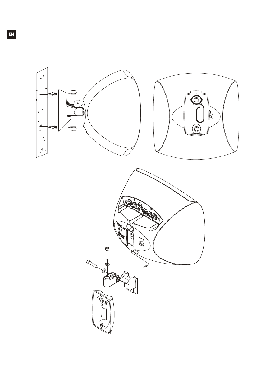
Wall mount set-up:
1. Drill two 6 mm. holes in the wall, matching the position of the bracket's holes.
2. Insert two 6 mm. wall plugs.
3. Hold the safety cable on the rear of the bracket (see diagram).
4. Place the bracket in its position, previously passing the safety cable and the signal
cable through the square hole of the bracket. Insert and tighten the screws, firmly
holding on to the wall mount bracket.
5. Connect the power cables, signal input and connection between the two units to the
connectors on the rear of the speaker. Pay attention to the correct polarity of the
Euroblock terminals.
6. Place the speaker in its final position by vertically sliding it down so that the guide on
the back fits with the guide on the rear of the brac ket. Insert the plastic rivet into the
hole in the rear of the speaker.
7. Attach the safety cable to the rear of the speaker so it does not accidentally fall down
and cause material or personal damage.
8. Turn the box to the desired position bot h vertically and horizontally. Tight en the Allen
screws to secure this position on both axes.
To operate the speakers, turn on the MAST ER (L) unit with the switch on the rear panel,
adjust the volume and equalize the sound to the desired position. The CLIP indicator warns of
power amplifier saturation due to an e xcess of s ignal. To avoid dis tort ion and pres erve t he sound
quality, it is important t hat this indic ator i s not constantl y lit while t he unit is in norm al operation. It
should light up periodically, based on the rhythm of the music's bass frequencies.
Page 6
6
NOTE: To protect the system from eventual overloads in the power line, there is a T1A
250V 5x20 mains fuse in the MASTER unit in a fuse holder located in the rear slot. In the
event that the fuse blows, unplug the unit, remove the wall mount bracket, unsc rew the fuse
holder, remove the fuse and replace it with an identical one. If the new fuse blows
immediately, please contact our Technical Services.
Page 7
7
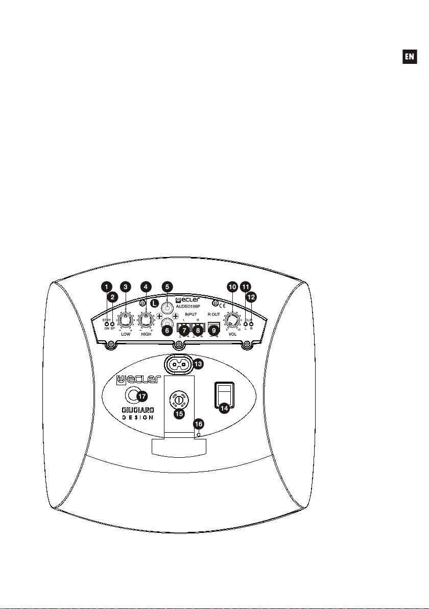
5. LIST OF FUNCTIONS
1. ON/STANDBY indicator light
2. SIGNAL PRESENT indicator light
3. LOW bass control
4. HIGH treble control
5. RCA unbalanced input in line 1 left L channel
6. RCA unbalanced input in line 1 right R channel
7. Euroblock balanced input in line 2 left L channel
8. Euroblock balanced input in line 2 right R channel
9. Amplified output right R channel
10. VOL output volume control
11. Indicator light for left channel clipping CLIP 12. Indicator light for right channel clipping CLIP
13. Mains socket (220-240VAC)
14. On/Off sw itch
15. Fuse holder
16. Hole for the locking rivet
17. Safety cable anchoring point
6. DIAGRAM OF FUNCTIONS
Page 8

8
Page 9

9
INSTRUCTION MANUAL
1. NOTA IMPORTANTE 10
2. PRECAUCIONES 10
3. INTRODUCCIÓN 10
4. UBICACIÓN, MONTAJE Y PUESTA EN MARCHA 11
5. LISTA DE FUNCIONES 13
6. DIAGRAMA DE FUNCIONES 13
7. DIAGRAMA DE CONFIGURACIÓN 26
8. CARACTERÍSTICAS TÉCNICAS 27
9. DIAGRAMA DE BLOQUES 28
Todos los datos están sujetos a variación debida a tolerancias de producción. ECLER S.A. se
reserva el derech o de re aliza r cambi os o m ejor as en la f abri cación o diseño q ue pudi eran af ectar l as
especificaciones.
Page 10

10
1. NOTA IMPORTANTE
Enhorabuena. Vd. posee el resultado de un cuidado diseño y de una esmerada
fabricación. Agradecemos su confianza por haber elegido nuestro conjunto de cajas acústicas
autoamplificadas AUDEO106P.
Para conseguir su má xima operatividad y r endimiento es MUY I MPORTANTE, ant es de
su conexión, leer deteni damente y tener muy presentes las consi deraciones que en este manual se
especifican. Para garant izar un óptim o funcionamient o, recomendamos que su m antenimient o sea
llevado a cabo por nuestros Servicios Técnicos autorizados.
2. PRECAUCIONES
No existen partes ajustables por el usuario en el interior de estos equipos.
No utilice este aparato cerca del agua.
No exponga los equipos a salpicaduras.
Evite colocar recipientes que contengan líquidos sobre ellos.
Evite colocar los equipos cerca de fuentes de calor, focos o estufas.
Utilice únicamente los accesorios especificados por el fabricante y adecuados a cada cometido.
3. INTRODUCCIÓN
AUDEO106P es la encarnación del éxito de la prestigiosa serie AUDEO en una fórmula
sencilla, de coste contenido y fácil manejo, ideal en multitud de aplicaciones multimedia y
audiovisuales. Una pareja estéreo de altavoces autoamplificados con unas prestaciones
excelentes y un diseño único, encajando fácilmente en clases de form ación, escuelas, salas de
reuniones y presentaciones multimedia, locales comerciales, etc.
Características principales:
• Pareja de altavoz autoamplificado + altavoz pasivo
• Altavoces “Full-range”, 2 vías (6” + 1”)
• Entrada estéreo balanceada Euroblock en unidad MASTER
• Entrada estéreo no balanceada RCA en unidad MASTER
• Enlace entre unidad MASTER y ESCLAVA a través de conectores Euroblock.
• Amplificador integrado 2 x 20 W RMS (unidad MASTER)
• Fuente de alimentación integrada (unidad MASTER)
• Función Auto stand-by (modo de reposo / ahorro de energía sin necesidad de encender y
apagar diariamente el equipo)
• Control de tonos de 2 bandas y control de volumen
• Sistema Anti-Clip integrado
• Indicadores LED ON / STD. BY, Signal Present y CLIP
• Construcción en ABS reforzado
• Disponible en blanco o negro
• Incluye soportes de pared y cable de acero de seguridad
• Compatible con los accesorios serie A UDEO para el montaje en sobremesa y sobre pie de
micrófono
Page 11

11
4. UBICACIÓN, MONTAJE Y PUESTA EN MARCHA
Como reglas generales se observarán las siguientes:
• Instalar siempre la unidad en superficies sólidas y firmes.
• Para una buena reproducción sonora no debe existir ningún obstáculo entre los
recintos y la audiencia.
• Adecue los niveles de presión sonora a las necesidades de reproducción. A pesar de
su reducido tamaño, AUDEO106P tiene un rendimiento muy superior al de los
altavoces domésticos.
En el embalaje de las AUDEO encontrará todo lo necesario para completar la instalación de
las dos unidades:
• Dos soportes articulados de montaje en pared (uno por caja)
• Cuatro tornillos y cuatro tacos de pared de 6mm (dos por caja)
• Dos remaches de plástico para bloqueo de las cajas a los soportes
• Llave Allen 5mm
• Dos latiguillos metálicos de seguridad contra eventuales desprendimientos (uno por
caja), con sus correspondientes tornillos y arandelas de fijación
• Dos conectores Euroblock de dos terminales y un tramo de cable de altavoz para el
enlace MASTER-SLAVE
• Dos conectores Euroblock de tres terminales para entrada estéreo balanceada INPUT
• Dos puentes para la configuración de la sensibilidad de entrada.
• Un cable de alimentación de la unidad MASTER mediante la red eléctrica
• Un Manual de instrucciones
• Impresos de garantía
Procedimiento de instalación en pared:
1. Realice dos taladros de 6 mm. en la pared, coincidiendo c on la posición de los orificios
del soporte.
2. Inserte en ellos dos tacos de pared de 6 mm.
3. Sujete el latiguillo de seguridad en el posterior del soporte (según diagrama).
4. Coloque el soporte en su ubicación, pasando previ amente el latiguillo y el cable del
altavoz por el orificio cuadrado del soporte. Inserte y enrosque los tornillos
suministrados, sujetando firmemente el soporte a la pared.
5. Conecte los cables de alimentación, entrada de señal y enlace entre las dos unidades
a los conectores de la parte trasera de la caj a. Preste atención a l a correcta polaridad
de los terminales Euroblock.
6. Sitúe la caja acústica en su posición fi nal deslizándola verticalmente haci a abajo para
que la guía de su cara posterior encaje con la guía del soporte. I nserte el remache de
plástico en el taladro previsto en el posterior de la caja.
7. Sujete el cable de seguridad en la parte posterior de la c aja acústica, con el objeto de
que ésta no caiga accidentalmente y ocasione daños materiales y/o personales.
8. Oriente la caja hasta obtener la posición deseada en los ejes vertical y horizontal.
Apriete los tornillos Allen del soporte para fijar dicha posición en ambos ejes.
Para poner en marcha el equipo, encienda l a unidad MASTER (L) mediante el interruptor
del panel posterior y ajuste el volumen y la ecualización a l as posiciones deseadas. El indicador
"CLIP" advierte de la saturaci ón de los amplificadores de potencia por exceso de s eñal. Es muy
importante, para evitar la distorsión y preservar la calidad sonora, que este indicador no se
encuentre permanentemente iluminado mientras la unidad permanece en régimen de
Page 12

12
funcionamiento normal, siendo admisible que se ilumine puntualmente al ritmo de las frecuencias
graves de la reproducción musical.
NOTA: Para proteger el sistema de eventuales sobrec argas en la línea eléctrica exist e un
fusible de red tipo T1A 250V 5x2 0 en la unidad MASTER, en un portaf usibles enroscable
ubicado en la ranura posterior. En caso de que éste se funda. desconecte el aparato,
retírelo del soporte de pared, desenrosque el portafusibl es, extraiga el fusible y sustitúyalo
por otro de idénticas características. Si el nuevo fus ible vol viese a fundirs e inmedi atamente,
consulte con nuestro Servicio Técnico.
Page 13

13
5. LISTA DE FUNCIONES
1. Indicador luminoso ON/STANDBY
2. Indicador luminoso SIGNAL PRESENT
3. Control de graves LOW
4. Control de agudos HIGH
5. Entrada no balanceada de línea 1 RCA canal izquierdo L
6. Entrada no balanceada de línea 1 RCA canal derecho R
7. Entrada balanceada de línea 2 Euroblock canal izquierdo L
8. Entrada balanceada de línea 2 Euroblock canal derecho R
9. Salida amplificada canal derecho R
10. Control de volumen salida VOL
11. Indicador luminoso de recorte canal izquierdo CLIP
12. Indicador luminoso de recorte canal derecho CLIP
13. Base de toma de red (220-240VAC)
14. Interruptor de puesta en marcha
15. Portafusible
16. Alojamiento para el remache de bloqueo
17. Punto de anclaje del cable de seguridad
6. DIAGRAMA DE FUNCIONES
Page 14

14 15
Page 15

NOTICE D’INSTRUCTIONS
1. NOTE IMPORTANTE 16
2. PRÉCAUTIONS 16
3. INTRODUCTION 16
4. EMPLACEMENT D'INSTALLATION, MONTAGE ET MISE EN MARCHE 17
5. LISTE DES FONCTIONS 19
6. SCHÉMA DE FONCTIONS 19
7. SCHÉMA DE CONFIGURATION 26
8. CARACTÉRISTIQUES TECHNIQUES 27
9. SCHÉMA FONCTIONNEL 28
Toutes les valeurs mentionnées dans ce document sont susceptibles d’être modifi é es en raison des
tolérances de production. ECLER SA se réserve le droit de changer ou d’améliorer les processus de
fabrication ou de conception de ses produits, entraînant ainsi des modifications au niveau des
spécifications techniques de ces derniers.
Page 16

16
1. NOTE IMPORTANTE
Félicitations ! Vous avez entre les m ains le résultat d' une conception et d'une fabricati on
soignées. Nous vous remerc ions de la confiance que vous nous avez témoignée en choisissant
notre ensemble d'enceintes acoustiques auto-amplifiées AUDEO106P.
Pour exploiter au mieux toutes les fonctionnal i t és et obtenir un rendement maximal de cet
appareil, il s'avère TRÈS IMPORTANT de lire attentivement et de suivre les recommandations de ce
manuel. Pour garantir u n foncti onnem ent optim al, nous rec ommandons que toute maint enance soit
effectuée par nos services techniques agréés.
2. PRÉCAUTIONS
L'intérieur de ces équipements ne contient aucun élément pouvant être réglé par
l'utilisateur.
Ne pas utiliser cet appareil à proximité d'un point d'eau.
Ne pas exposer les équipements à des éclaboussures.
Éviter de poser des récipients contenant des liquides sur les équipements.
Éviter de placer les équipements à proximité de sources de chaleur, de projecteurs ou de
radiateurs.
N'utiliser que les accessoires préconisés par le fabricant et adaptés à chaque application.
3. INTRODUCTION
Le modèle AUDEO106P est l'incarnation même du succès rencontré par la
prestigieuse série AUDEO. Cette formule simplifiée, de coût abordable et facile à utiliser, est
idéale pour de nombreuses applications multimédias et audiovisuelles. Ce couple st éréo de hautparleurs auto-amplifiés aux perform ances excellentes et au style uni que convient à la perfecti on
aux cours de formation, aux écoles, aux salles de réunion et de présentati on multimédia, aux
locaux commerciaux, etc.
Caractéristiques principales :
• Couple haut-parleur auto-amplifié + haut-parleur passif
• Haut-parleurs à gamme étendue à 2 voies (6” + 1”)
• Entrée stéréo symétrique Euroblock sur unité MAÎTRE
• Entrée stéréo non symétrique RCA sur unité MAÎTRE
• Liaison entre les unités MAÎTRE et ESCLAVE à travers des connecteurs Euroblock
• Amplificateur intégré 2 x 20 W RMS (unité MAÎTRE)
• Source d'alimentation intégrée (unité MAÎTRE)
• Fonction Auto stand-by (mode de veille/économi e d'énergie sans avoir à allumer et éteindre
l'appareil tous les jours)
• Contrôle d'égalisation à 2 bandes et contrôle du volume
• Système anti-saturation intégré
• Voyants DEL ON / STD. BY, présence de signal et CLIP (saturation)
• Fabrication en ABS renforcé
• Disponible en blanc ou noir
• Supports muraux et élingue de sécurité en acier inclus
• Compatible avec les accessoires de la série AUDEO pour montage sur t able et sur pied de
microphone
Page 17

17
4. EMPLACEMENT D'INSTALLATION, MONTAGE ET MISE EN MARCHE
En règle générale, il convient de prendre les aspects ci-dessous en considération :
• installer systématiquement l'unité sur des surfaces solides et stables ;
• pour une bonne reproduction sonore, aucun obstacle ne doit se trouver entre les
enceintes acoustiques et le public ;
• adapter les niveaux de pression sonore aux besoins de diffusion. Malgré leurs
dimensions réduites, les enceintes AUDEO106P affichent des performances bien
supérieures à celles des haut-parleurs domestiques.
Tous les éléments nécessaires à l'ins tallation complète des deux enceintes AUDEO sont
fournis à l'intérieur de l'emballage :
• deux supports articulés de montage mural (un par enceinte)
• quatre vis et quatre chevilles murales de 6 mm (deux par enceinte)
• deux rivets en plastique pour le blocage des enceintes aux supports
• une clé Allen de 5 mm
• deux élingues métalliques de sécurité pour prévenir les décrochements éventuels
(une par enceinte), accompagnées de leurs vis et rondelles de fixation correspondantes
• deux connecteurs Euroblock à deux broches et un tronçon de câble de haut-parleur pour
la liaison MAÎTRE-ESCLAVE
• deux connecteurs Euroblock à trois broches pour l'entrée stéréo symétrique INPUT
• deux cavaliers pour la configuration de la sensibilité d'entrée
• un câble d'alimentation de l'unité MAÎTRE pour le raccordement au secteur
• une notice d'instructions
• des formulaires de garantie
Procédure d'installation au mur :
1. percer deux trous de 6 mm dans le m ur corres pondant à l' emplacement des orif ices du
support ;
2. y introduire deux chevilles murales de 6 mm ;
3. fixer l'élingue de sécurité à l'arrière du support (comme indiqué sur la figure) ;
4. positionner le support à son emplacement en faisant préalablement passer l'élingue de
sécurité et le câble du haut-parleur dans l'orifice carré du support ; introduire et serrer
les vis fournies en fixant fermement le support contre le mur ;
5. raccorder les câbles d'alimentation, d'entrée de signal et de liaison entre les deux
unités aux connecteurs de la partie arrière de l'enceinte ; prêter une attention
particulière à la polarité des bornes Euroblock ;
6. placer l'enceinte acoustique dans sa position final e en la faisant glisser verticalement
vers le bas, de manière à ce que le guide de sa face arrière s'emboîte dans le guide du
support ; insérer le rivet en plastique dans le trou prévu à cet effet à l'arrière de
l'enceinte ;
7. fixer l'élingue de sécurité à la partie arri ère de l'enceinte acoustique afin d'évit er toute
chute accidentelle susceptible de provoquer des dommages matériels et/ou corporels ;
8. orienter l'enceinte dans la position souhaitée en la déplaçant s ur les axes vertical et
horizontal. Serrer les vis Allen du support pour maintenir l' enceinte en position sur les
deux axes.
Pour mettre l'appareil en marche, allumer l'unité MAÎTRE (L) à l'aide de l'interrupteur du
panneau arrière et régler le volume ainsi que l'égalisation dans les positions souhaitées.
L'allumage du voyant CLIP indique la saturation des am plificateurs de puissance en raison d'un
Page 18

18
excès du signal. Pour éviter toute distorsion et préserver la qualité sonore, il s'avère très
important que ce voyant ne reste pas allumé en permanenc e lorsque l'unité se trouve en régime
de fonctionnement normal. Seul son allumage ponctuel au rythme des fréquences les plus graves
de la reproduction musicale est autorisé.
REMARQUE : Pour protéger le système contre les surcharges éventuelles de la ligne
électrique, un fusible de secteur de type T 1 A 250 V 5x20 est présent sur l'unité MAÎTRE.
Celui-ci se trouve sur un porte-fusible vissable situé sur la rainure arrière. En cas de fonte
du fusible, débrancher l'appareil, le retirer du s upport mural, dévisser le porte-fusible, en
retirer le fusible et le remplacer par un fusible poss édant les mêmes caractéristiques. En cas
de fonte immédiate du nouveau fusible, contacter le service technique.
Page 19

19
5. LISTE DES FONCTIO N S
1. Voyant lumineux ON/STANDBY
2. Voyant lumineux SIGNAL PRESENT
3. Contrôle des graves LOW
4. Contrôle des aigus HIGH
5. Entrée non symétrique de ligne 1 RCA, voie gauche L
6. Entrée non symétrique de ligne 1 RCA, voie droite R
7. Entrée symétrique de ligne 2 Euroblock, voie gauche L
8. Entrée symétrique de ligne 2 Euroblock, voie droite R
9. Sortie amplifiée, voie droite R
10. Contrôle du volume de sortie VOL
11. Voyant lumineux d'écrêtage de la voie gauche CLIP
12. Voyant lumineux d'écrêtage de la voie droite CLIP
13. Base de prise de secteur (220-240VAC)
14. Interrupteur de mise en marche
15. Porte-fusible
16. Logement du rivet de blocage
17. Point d'ancrage du câble de sécurité
6. SCHÉMA DE FONCTIONS
Page 20

20 21
Page 21

BEDIENUNGSANLEITUNG
1. WICHTIGER HINWEIS 22
2. VORSICHTSMASSNAHMEN 22
3. EINLEITUNG 22
4. EINBAUORT, EINBAU UND INBETRIEBNAHME 23
5. LISTE DER FUNKTIONEN 25
6. FUNKTIONSDIAGRAMM 25
7. KONFIGURATIONSÜBERSICHT 26
8. TECHNISCHE DATEN 27
9. BLOCKSCHALTBILD 28
Aufgrund von F ertigungstoleranzen kö nnen die Angaben von den tatsächlich gemess enen Werten
abweichen. ECLER S.A. behält sich fertigungs- und entwicklungsbedingte Veränderungen oder
Verbesserungen am Gerät vor, durch die sich bestimmte Spezifikationen verändern können.
Page 22

22
1. WICHTIGER HINWEIS
Herzlichen Glückwunsch! Sie haben ein hochwertiges Gerät erworben, das Ergebnis
eines hohen Entwicklungsaufwandes und sorgfältiger Fertigung ist. Wir bedanken uns für das
Vertrauen, das Sie uns durch den Kauf des Selfpowered-Lautsprechersystems AUDEO106P
entgegengebracht haben.
Um eine optimale Betriebs fähigkei t und die maximal e Leistung zu err eichen, is t es SEHR
WICHTIG, vor dem Anschluss des Geräts di e i n di eser Anleitung enthaltenen Hinweise aufmerksam
durchzulesen und zu berücksichtigen. Reparaturen sollten nur von unseren zugelassenen
Kundendienst-Abteilungen durchgeführt werden, um einen optimalen Betrieb sicherzustellen.
2. VORSICHTSMASSNAHMEN
Im Inneren dieser Geräte befinden sich keine, durch den B enutzer einstellbaren
Teile.
Es dürfen kein Wasser oder andere Flüssigkeiten in das Gerät gelangen.
Achten Sie darauf, dass die Geräte keinen Belastungen durch Spritzwasser
ausgesetzt sind.
Vermeiden Sie es, Gefäße mit Flüssigkeiten darauf abzustellen.
Die Geräte dürfen nicht in der Nähe von Wärmequellen wie Heizungen oder Scheinwerfern
aufgestellt werden.
Benutzen Sie ausschließlich das vom Hersteller empfohlene Einbauzubehör, das für den
jeweiligen Zweck geeignet ist.
3. EINLEITUNG
Der AUDEO106P verkörpert den Erfolg der renommierten AUDEO-Serie in einer
einfachen, preisbewussten und bedienerfreundlichen Formel, die ideal für eine Vielzahl an
Multimedia- und audiovisuellen Anwendungen ist. Ein Selfpowered-Stereo-Laut sprecherpaar mit
exzellenten Leistungsmerkmalen und einem einzigartigen Design, das mühelos in
Schulungsräume, Schulen, Besprechungs- und Präsentationsräume, gewerbliche Räume usw.
integriert werden kann.
Wesentliche Merkmale:
• Selfpowered-Lautsprecherpaar + Passivlautsprecher
• Fullrange-2-Wege-Lautsprecher (6” + 1”)
• Symmetrischer Euroblock-Stereo-Eingang in der MASTER-Einheit
• Unsymmetrischer Cinch-Stereo-Eingang in der MASTER-Einheit
• Verbindung von MASTER- und SLAVE-Einheit über Euroblock-Stecker.
• Integrierter Verstärker mit 2 x 20 W RMS (MASTER-Einheit)
• Integriertes Netzteil (MASTER-Einheit)
• Auto-Standby-Funktion (Ruhe-/Energiesparmodus ohne notwendiges tägliches Ein/Ausschalten der Geräte)
• Separate 2-Band-Klang- und Lautstärkeregelung
• Integriertes Anti-Clip-System
• LED-Anzeigen für ON / STD. BY, Signal Present und CLIP
• Gehäuse aus verstärktem ABS
• Verfügbar in weiß oder schwarz
• Einschließlich Wandhalterung und Sicherheits-Stahlkabel
• Kompatibel zum Zubehör der AUDEO-Serie zur Tischmontage und Montage auf
Mikrofonständer
Page 23

23
4. EINBAUORT, EINBAU UND INBETRIEBNAHME
Es sind folgende Grundregeln zu beachten:
• Stellen Sie die Einheit immer auf festen Untergrund.
• Für eine zufriedenstellende Tonwiedergabe dürfen zwischen den Lautsprechern und
dem Publikum keine Hindernisse stehen.
• Passen Sie die Schalldruckpegel an die Wiedergabebedürfnisse an. Trotz seiner
geringen Abmessungen hat der AUDEO106P eine viel höhere Leistung als
Heimlautsprecher.
In der Verpackung der AUDEO finden Sie alles Notwendige für die Installation der beiden
Einheiten:
• Zwei Gelenkhalterungen zur Wandmontage (eine je Lautsprecher)
• Vier Schrauben und vier 6-mm-Dübel (zwei pro Lautsprecher)
• Zwei Kunststoffniete zur Fixierung der Lautsprecher auf den Halterungen
• 5-mm-Innensechskantschlüssel
• Zwei Sicherungskabel gegen mögliches Herausfallen aus den Halterungen (eines pro
Lautsprecher) mit den entsprechenden Befestigungsschrauben und -scheiben
• Zwei Euroblock-Stecker mit zwei Anschlüssen und einem Lautsprecherkabel für die
Verbindung von MASTER und SLAVE
• Zwei Euroblock-Stecker mit drei Anschlüssen für den symmetrischen INPUT-Stereoeingang
• Zwei Brücken zur Konfiguration der Eingangsempfindlichkeit.
• Ein Netzkabel für die MASTER-Einheit
• Eine Bedienungsanleitung
• Garantiekarten
Vorgehensweise zur Wandmontage:
1. Bohren Sie entsprechend den Bohrungen in der Halterung zwei Löcher mit 6 mm in die
Wand.
2. Setzen Sie die beiden 6-mm-Dübel in die Wand.
3. Befestigen Sie das Sicherungskabel an der Halterungsrückseite (siehe Abbildung).
4. Setzen Sie die Halterung an den Einbauort und führen Sie vorher das Sicherungs- und
das Lautsprecherkabel durch die quadratische Öffnung der Halterung. Setzen Sie die
mitgelieferten Schrauben ein und sc hrauben Sie die Wandhalterung damit fest an die
Wand.
5. Schließen Sie das Netzkabel, das Signaleingangskabel und das Verbindungskabel
zwischen den beiden Einheiten an die St ecker der Gehäuserückseite an. Achten Sie
auf die richtige Polarität der Euroblock-Steckverbinder.
6. Bringen Sie den Lautsprecher in seine Endstel lung. Setzen Sie ihn über die Führung
an der Rückseite in die Führung der Halterung und schieben Sie ihn nach unten.
Drücken Sie den Kunststoffniet an der Rückseite des Lautsprechers in die dafür
vorgesehene Bohrung.
7. Befestigen Sie das Sicherungskabel an der Rüc kseite des Lautsprechers, damit dieser
nicht unabsichtlich herabfallen und so Schäden oder Verletzungen hervorrufen kann.
8. Richten Sie den Lautsprecher vertik al und horizontal wie gewünscht aus. Drehen Sie
die Innensechskantschrauben der Halterung fest, um die Stellung zu fixieren.
Schalten Sie zur Inbetriebnahme die MASTER-Einheit (L) über den Schalter an der
Rückseite ein und stellen Sie die Laut stärke und den Equalizer auf die ge wünschten Werte ein.
Die CLIP-Anzeige warnt vor der Übersteuerung des Leistungsverstärkers für den Fall ei nes zu
Page 24

24
starken Signals. Um Verzerrungen zu vermeiden und die Klangqualität zu erhalt en, ist es äußerst
wichtig, dass die Anzeige nicht perm anent aufleuchtet, während die Einheit normal funktioni ert.
Es ist jedoch zulässig, dass sie bei der Musikwiedergabe im Rhythmus der Bässe aufflackert.
HINWEIS: Um das System vor eventuellen elektrischen Überlastungen zu schüt zen, ist eine
Netzsicherung des Typs T1A 250V 5x20 in der MASTER-Einheit in einen Si cherungshalter
in der rückwärtigen Führung eingeschraubt. Schmilzt diese, schalten Sie das Gerät ab,
nehmen Sie es von der Wandhalterung ab, drehen Sie den Sicherungshalter heraus,
entnehmen Sie die Sicherung und ersetzen Sie sie durc h eine gleichwertige. Falls die neue
Sicherung gleich danach wieder schmilzt, wenden Sie sich an unseren Kundendienst.
Page 25

25
5. LISTE DER FUNKTIONEN
1. LED-Anzeige für ON/STANDBY
2. LED-Anzeige für SIGNAL PRESENT
3. Tiefenregler LOW
4. Höhenregler HIGH
5. Unsymmetrischer Eingang Line 1 Cinch Kanal L
6. Unsymmetrischer Eingang Line 1 Cinch Kanal R
7. Symmetrischer Eingang Line 2 Euroblock Kanal L
8. Symmetrischer Eingang Line 2 Euroblock Kanal R
9. Verstärkter Ausgang Kanal R
10. Lautstärkeregler VOL Ausgang
11. LED-Anzeige Verzerrung linker CLIP-Kanal
12. LED-Anzeige Verzerrung rechter CLIP-Kanal
13. Steckdose für die Stromversorgung (220-240VAC)
14. Betriebsschalter
15. Sicherungshalter
16. Bohrung für Verriegelungsniet
17. Befestigungspunkt des Sicherheitskabels
6. FUNKTIONSDIAGRAMM
Page 26

26
7. CONFIGURATION DIAGRAM 7. DIAGRAMA DE CONFIGURACIÓN
Gain 0dB
Auto Standby ON
JUMPERS FACTORY ADJUST
-10dB
J116
J117
Gain
J114
J115
0dB
Auto Stdby
off
J105
on
J107
J106
7. SCHÉMA DE CONFIGURATION 7. KONFIGURATIONSÜBERSICHT
Page 27

27
8. TECHNICAL CHARACTERISTICS 8. CARACTERÍSTICAS TÉCNICAS
POWER
2x18W@4Ω 1% THD
2x22W@4Ω 10% THD
Frequency response
40Hz - 50kHz (-3dB)
THD+Noise @ 1kHz Full Pwr.
<0.15%
Inputs Sensitivity nom/Impedance
LINE UNBAL
0dBV (-10dBV*)/>22kΩ
LINE BAL
-10dBV/>22kΩ
CMRR
LINE BAL
>60dB @ 1kHz
Tone control
BASS
100Hz ±10dB
TREBLE
10KHz ±10dB
Signal Noise Ratio
LINE
>75dB
Auto Standby*
LEVEL
-40dBV aprox.
TIME
2min. aprox.
Power consumption (pink noise, 1/8 power @
4ohm)
15VA/10W
Power consumption (pink noise, 1/3 power @
4ohm)
24VA/18W
Power consumption Standby
<3W
Mains power
Integrated
power supply
220-240VAC
Dimensions WxDxH
242x242x163mm
Weight
Active cabinet
2,5kg
Passive cabinet
1,7kg
*Internally selectable
8. CARACTÉRISTIQUES TECHNIQUES 8. TECHNISCHE DATEN
Page 28

28
9. BLOCK DIAGRAM 9. DIAGRAMA DE BLOQUES
9. SCHÉMA FONCTIONNEL 9. BLOCKSCHALTBILD
50.0246.01.01
ECLER Laboratorio de electro-acústica S.A.
Motors 166-168, 08038 Barcelona, Spain
INTERNET http://www.ecler.com E-mail:
info@ecler.es
 Loading...