

Page 1

USER MANUAL
MANUAL DE INSTRUCCIONES
NOTICE D'UTILISATION
BEDIENUNGSANLEITUNG
Page 2

Page 3

INSTRUCTION MANUAL
1. IMPORTANT REMARK 04
1.1. Conformity with international standards 04
2. INTRODUCTION 04
3. INSTALLATION 05
3.1. Placement and mounting 05
3.2. Mains connection 05
3.3. Input connections 06
3.4. Input options 06
3.5. Output connections 06
4. OPERATION AND USAGE
07
4.1. Start up 07
4.2. Input attenuation 07
4.3. Remote control 07
4.4. Connection of the VCA control 07
4.5. AUTO POWER OFF function 08
4.6. Indicators 08
5. CLEANING 08
6. FUNCTION LIST 09
7. FUNCTION DIAGRAM 09
8. CONFIGURATION DIAGRAM 34
9. TECHNICAL CHARACTERISTICS 35
10. BLOCK DIAGRAM 36
All numbers subject to variation due to production tolerances. ECLER SA reserves the right to
make changes or improvements in manufacturing or design which may affect specifications.
3
Page 4

1. IMPORTANT REMARK
Congratulations! You are the owner of a carefully designed and manufactured equipment.
We thank you for having purchased our compact amplifier AMPACK.
It is VERY IMPORTANT that you read this manual before connecting the amplifier in order
to obtain its maximum performance.
We recommend our authorised Technical Services whenever any maintenance task should
be needed so that optimum operation shall be achieved.
1.1. Conformity with international stan dards
The AMPACK amplifier series complies with the following international standards:
•
EN55103-1
•
Product family standard for audio, video, audio-visual and entertainment lightning control apparatus
Electromagnetic compatibility.
for professional use
• Part 1: Emission
•
EN55103-2
Electromagnetic compatibility.
• Product family standard for audio, video, audio-visual and entertainment lightning control apparatus
for professional use
• Part 2: Immunity
•
EN60065
Audio, video and similar electronic apparatus. Safety requirements
Guidelines 73/23/EEC and 2004/108/EC are therefore accomplished
2. INTRODUCTION
The compact amplifiers AMPACK series offers the most resistant and reliable amplification
technology available. Its design allows its usage in nearly every place and application that requires
power values up to 80W RMS at low impedance.
The AMPACK series offers the following features:
•
78W RMS (AMPACK80) / 24W RMS (AMPACK25) stereo amplifier
•
220-240V 50/60Hz power supply
•
AUTO POWER OFF: when no signal is present on the input, the AMPACK unit enters the standby
mode, reducing its power consume
•
Stereo, parallel and bridge operation possible
•
VCA based remote control for attenuation. Independent for ea ch input channel
•
EUROBLOCK connectors for VCA input, output and control
•
Additional stereo RCA input connector
•
Independent gain controller for each channel
•
100Hz high pass filter
•
Controllers protected against accidental manipulation
•
Can be directly installed on 35mm DIN r ail or individual holde r
4
Page 5

3. INSTALLATION
3.1. Placement and mounting
The AMPACK series offers a huge variety of installation
possibilities as p.eg:
•
Installation on 35mm DIN rail
•
Desktop installation using the included accessories.
•
False ceiling / partition wall: this accessory allows fixing the unit
using screws or flanges prepared for this usage.
3.2. Mains connection
The amplifier is powered with alternate current, 220-240V 50/60Hz. The maximum power
consumption is 296VA for the AMPACK80 and 93VA for the AMPACK25. The power installation has to
be able to deliver these power values.
The amplifier should have an earth connection in good conditions (earth resistance, Rg=30Ω
or less). The environment must be dry and dustless. Do not ex pos e th e u ni t t o rai n o r wat er sp la sh es,
and do not place liquid containers or incandescent objects like candles on top of the unit. Do not
obstruct the ventilation grids with any kind of material.
In case there is some type of intervention and/or connection-disconnection of the amplifier, it
is most important to previously disconnect the mains power supply. There are no us er or serv iceab le
parts inside the amplifier.
You should avoid that the supply cable twists with the shielded signal cables, as this could
lead to unwanted hum.
The indicated situations can produce hum noise. To avoid this, the AMPACK series wears an
additional high pass filter with fixed cut-off frequency at 100Hz. This filter can be easily activated using a
jumper as shown on the configuration diagram.
In order to protect the unit from an eventual electrical overload or momentary power peaks
from the internal circuits it carries a fuse. Should it ever blow up, unplug the unit from mains and
replace it with an identical one. If the new fuse blows again contact immediately with our Authorized
Technical Service.
CAUTION: YOU MUST NEVER USE A HIGHER VALUE FUSE.
5
Page 6
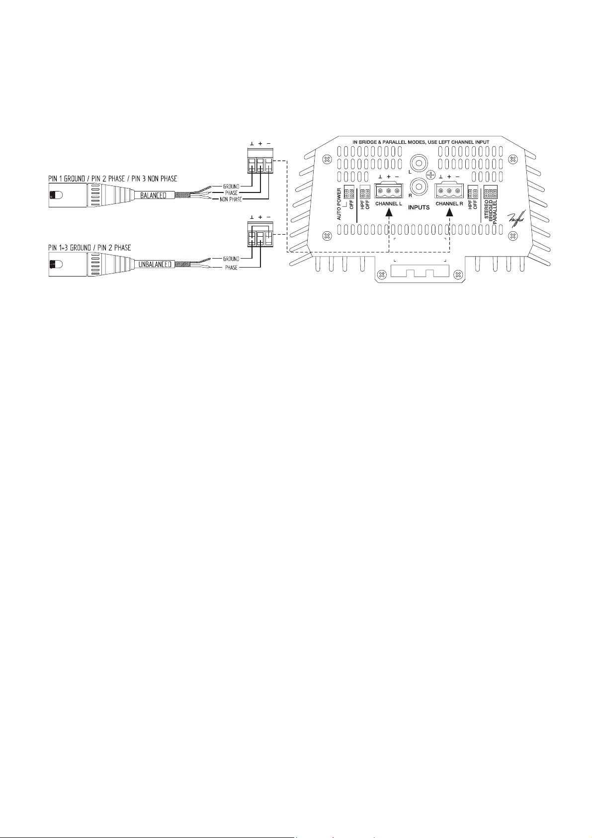
3.3. Input connections
The signal input use electronically balanced EUROBLOCK connectors with input impedance
greater than 20kΩ and a nominal sensitivity of 0dBV(1V). The pin out is as follow s:
There is an additional stereo, unbalanced, stereo RCA input to connect audio source as
CD’s, DVD’s, satellite receivers, etc…
3.4. Input options
The AMPACK admits the following operation modes, which can be selected easily using
the configuration jumpers. You have to use tweezers or another appropriate tool to move the
jumpers.
•
Stereo
•
Parallel: for mono applications. In this mode, the R input is inhibited, so that the signal present
on the L input (EUROBLOCK or RCA) will be the only valid signal. This signal will be amplified
and sent to both OUT L and OUT R outputs.
•
Bridge: for mono applications. In this mode, the R input is inhibited, so that the signal present
on the L input (EUROBLOCK or RCA) will be the only valid signal. In bridge mode the
AMPACK80 delivers 124W RMS and the AMPACK25 36W RMS. Please connect the output
cables as shown on the unit when using the bridge mode.
The AMPACK is configured for stereo mode by default.
3.5. Output connections
The outputs (15, 16) located at the rear panel ha ve terminals w hich can be scr ewe d on.
The cables that connect the AMPACK’s outputs with the loudspeakers must offer high
quality, with sufficient section and as short as possible. This is especially important when the
distance between amplifier and speakers are great; a section of at least 2.5mm
distances up to 10m; for greater distances, section should be greater than 4mm
2
is recommended for
2
.
Remember that the minimum operation impedance is 4Ω when using the amplifier in mono or
stereo and 8Ω when using the bridge mode. For a correct operation of the AMPACK lower impedances
than the ones described previously should no t be u sed.
Attention: in bridge mode only can be used the indicated terminals.
6
Page 7

4. OPERATION AND USAGE
4.1. Start up
This can be done using the power switch (20) and immediately the ON / STANDBY led (7)
will start lightning. We highly recommend the "safe power up sequence": First the sound sources,
then mixer, equalizers and active filters and, finally, power amplifiers. Powering off should be done
by following the exact reverse sequence in order to avoid any possible peaks reaching the next
device, and consequently protecting the loudspeakers, which are specially sensitive to these peaks.
4.2. Input attenuation
These are rotary trimmers located on the front panel (1, 4).
These attenuators allow the connection of different mixers, an independent volume control
and the connection of speakers not able to handle the amplifiers maximum output power, thus
avoiding the risk of damaging them with the mixers or preamps volume control.
An independent level adjustment can be done using a screwdriver or another appropriate tool.
4.3. Remote control
The AMPACK rear panel offers one terminal per amplifier to remotely control the volume,
using the built-in “VCA” circuit.
The combined usage of the rotary potentiometers located at the front panel (1, 4) and the
remote VCA (17, 18) control determines the final value of the signal’s attenuation for each input
channel. Therefore, a certain value can be fixed for the signal attenuation using the rotary so that the
remote control via VCA will not exceed this value and viceversa, that is, the two controls are
connected in series.
4.4. Connection of the VCA control
As already mentioned in the introduction of this manual, the signal attenuation level for each
of the input channels can be set using the following methods:
a) Using a remote potentiometer with nominal r esistance betw een 10kΩ and 50kΩ.
b) Using a device that generates a control voltage from 0 to 10V DC.
c) Using remote relays/dry contacts.
7
Page 8

NOTE: it is possible to connect a maximum of 16 inputs to one control potentiometer. It is necessary that
the ground terminals of all amplifiers are connected.
The connection cables can be up to 500m long if a section of 0,5mm
2
is used.
Consult the available accessories at your ECLER dealer or at w w w .ecler.com.
4.5. AUTO POWER OFF function
The AUTO POWER OFF function makes the installation of the AMPACK series more flexible
in places with difficult access, because it allows to leave the unit connected to the 220-240V 50/60Hz
supply while this will activate or deactivate itself automatically depending if there is an input signal
present or not.
In case that the level of the signal present on any of the inputs is lower than -22dBV for more
than 2 minutes, the AMPACK will switch automatically into STANDBY mode. This will be
correspondingly indicated by the ON/STANDBY led located on the unit’s upper panel, which switches
from green (ON) to red (STANDBY).
When in STANDBY mode, the power consumption of the AMPACK25 and the AMPACK80 is
lower than 10VA.
When the signal level becomes higher than -22dBV the device will automatically switch to ON
mode.
4.6. Indicators
The SP signal presence indicators (3, 5) light up when the input signal reaches
approximately -40dBV.
The CLIP indicators (2, 6) light up when the output signal for the speakers is -1,5dB below
the actual clipping threshold. This clipping system watches for eventual supply voltage variations,
thus giving always an accurate clipping indication, regardless of mains voltage deviations. It is
normal that when operating at high output power, the CLIP indicators light up in synchronisation with
the low frequencies, which carry the most energy. Nevertheless, you should avoid that the CLIP
indicators are lit continuously.
5. CLEANING
The AMPACK should not be cleaned with dissolvent or abrasive substances because
silk-printing could be damaged. To clean it, use a soft cloth slightly wet with water and neutral liquid
soap; dry it with a clean cloth. Be careful that water never gets into the amplifier through the holes of
the front panel.
8
Page 9

6. FUNCTION LIST
1. Left channel volume, VOL L
2. Left channel signal clip indicator, CLIP
3. Left input signal present indicator, SP
4. Right channel volume, VOL R
5. Right input signal present indicator, SP
6. Right channel clip indicator, CLIP
7. Operation indicator, ON / STANDBY
8. Automatic power off configuration, AUTO POWER
9. Left channel high pass filter configuration, HPF
10. Left channel balanced signal input, CHANNEL L
11. Signal input RCA connector, L R
12. Right channel balanced signal input, CHANNEL R
13. Right channel high pass filter configuration, HPF
14. Operation mode configuration, STEREO BRIDGED PARALLEL
15. Left channel output, OUT L
16. Right channel output, OUT R
17. Left channel remote control, CH L
18. Right channel remote control, CH R
19. Fuse holder
20. Power on switch, POWER
21. Mains socket
7. FUNCTION DIAGRAM
9
Page 10

10
Page 11

MANUAL DE INSTRUCCIONES
1. NOTA IMPORTANTE 12
1.1. Conformidad con normativas internacionales 12
2. INTRODUCCIÓN 12
3. INSTALACIÓN 13
3.1. Ubicación y montaje 13
3.2. Conexión a red 13
3.3. Conexiones de entrada 14
3.4. Opciones de entrada 14
3.5. Conexiones de salida 14
4. OPERACIÓN Y USO 15
4.1. Puesta en funcionamiento 15
4.2. Atenuadores de entrada 15
4.3. Control remoto 15
4.4. Conexionado del control VCA 15
4.5. Funcionalidad AUTO POWER OFF 16
4.6. Indicadores 16
5. LIMPIEZA 16
6. LISTA DE FUNCIONES 17
7. DIAGRAMA DE FUNCIONES 17
8. DIAGRAMA DE CONFIGURACIÓN 34
9. CARACTERÍSTICAS TÉCNICAS 35
10. DIAGRAMA DE BLOQUES 36
Todos los datos están sujetos a variación debida a tolerancias de producción. ECLER S.A. se
reserva el derecho de realizar cambios o mejoras en la fabricación o diseño que pudieran afectar
las especificaciones.
11
Page 12

1. NOTA IMPORTANTE
¡Enhorabuena!. Vd. posee el resultado de un cuidadoso diseño y una esmerada fabricación.
Agradecemos su confianza por haber elegido nuestr o amplifica dor compa cto AMPACK.
Para conseguir la máxima operatividad del aparato y su máximo rendimiento, es MUY
IMPORTANTE antes de su conexión, leer detenidamente y tener muy presentes las consideraciones
que en este manual se especifican.
Para garantizar el óptimo funcionamiento de este aparato, recomendamos que su
mantenimiento sea llevado a cabo por nuestros Servicios Técnicos autorizados.
1.1. Conformidad con normativas internacionales
La línea de amplificadores AMPACK es conforme a las siguientes normativas internacionales:
•
EN55103-1
Compatibilidad Electromagnética.
• Norma de familia de Productos para aparatos de uso profesional de sonido, vídeo, sistemas
audiovisuales y para el control de iluminación para espectácu los
• Parte 1: Emisión
•
EN55103-2
Compatibilidad Electromagnética.
• Norma de familia de Productos para aparatos de uso profesional de sonido, vídeo, sistemas
audiovisuales y para el control de iluminación para espe ctáculos
•
Parte 1: Inmunidad
•
EN60065
Aparatos de audio, vídeo y aparatos análogos. Requisitos de seguridad
Cumpliendo los requisitos de las directrices 73/23/CEE y 2004/108/CE
2. INTRODUCCIÓN
La gama de amplificadores compactos AMPACK ofrece al instalador la tecnología en
amplificación más robusta y fiable del mercado del audio profesional en un formato que permite su uso
en prácticamente cualquier lugar y aplicación en que se requiera potencias de hasta 80W RMS en baja
impedancia.
Sobre esta base funcional, la línea AMPACK ofrece el siguien te conjunto de pr estaciones:
•
Amplificador estéreo 78W RMS (AMPACK80) 24W RMS (AMPACK25)
•
Fuente de alimentación incorporada 220-240V 50/60Hz
•
AUTO POWER OFF: en caso de ausencia de señal la unidad AMPACK entra en modo Standby
quedando su consumo reducido
•
Admite funcionamiento estéreo, paralelo y puente
•
Control remoto de atenuación VCA independiente para cada canal de entrada
•
Conectores EUROBLOCK de entrada, salida y control VCA
•
Conector adicional de entrada estéreo RCA
•
Ajuste independiente de ganancia para cada entrada
•
Filtro 100 Hz pasa altos incorporado
•
Ajustes protegidos contra manipulación accidental
•
Directamente instalable en carril DIN 35mm o soporte individual
12
Page 13

3. INSTALACIÓN
3.1. Ubicación y montaje
La línea AMPACK admite una gran variedad de
posibilidades de instalación, entre las que se incluye:
•
Instalación en carril DIN 35mm
•
Sobremesa mediante el accesorio incluido.
•
Falso techo / tabiquería seca: el accesorio permite la fijación del
aparato mediante tornillos o bridas adecuadas a tal efecto.
3.2. Conexión a red
El amplificador se alimenta con corriente alterna, 220-240V 50/60Hz, su consumo a plena
potencia es de 296 VA en el caso del AMPACK80 y de 93 VA en el caso del AMPACK25, por ello es
importante que la instalación de red sea la adecuada a tales consumos.
La etapa debe conectarse a una toma de tierra en condiciones (Resistencia de tierra,
Rg=30Ω o menos). El ambiente de trabajo deberá ser seco y estar totalmente libre de polvo. No
exponga el aparato a la caída de agua o salpicaduras, no ponga encima objetos con líquido ni
fuentes de llama desnuda, como velas. No obstruya los orificios de ventilación con ningún tipo de
material.
En caso de requerir alguna intervención y/o conexión-desconexión del amplificador debe
desconectarse previamente la alimentación. En el interior del amplificador no existen elementos
manipulables por el usuario.
Debe evitarse que el cable de red se entremezcle con los cables blindados que transportan la
señal de audio, ya que ello podría ocasionar zumbidos.
Adicionalmente y como medida correctora para zumbidos ocasionados por situaciones como
la indicada, la línea AMPACK dispone de un filtro pasa altos incorporado con frecuencia de corte fija de
100Hz. El filtro puede ser fácilmente activado mediante jumper tal y como se indica en el diagrama de
configuración.
Para proteger al amplificador de eventuales sobrecargas en la línea de red o bien excesos
ocasionales en el consumo de los circuitos internos, está provisto de un fusible de red. En caso de
que éste se fundiera se desconectaría el aparato y se sustituiría por otro de idénticas características.
Si éste último se volviera a fundir, consulte con nuestro Servicio Técnico
PRECAUCIÓN: EN NINGÚN CASO DEBE PONERSE UN FUSIBLE DE VALOR MÁS
ELEVADO.
13
Page 14

3.3. Conexiones de entrada
Las entradas de señal son del tipo EUROBLOCK balanceadas electrónicamente, con una
impedancia de entrada superior a 20kΩ y una se ns i bi li d ad no mi na l d e 0 dB V (1V ) . La asignación es la
siguiente:
Adicionalmente, se dispone de una entrada RCA estéreo no balanceada para el
conexionado directo de fuentes de audio como CD, DVDs, receptores satélite, etc...
3.4. Opciones de entrada
El AMPACK permite los siguientes modos de trabajo seleccionables de forma sencilla
mediante el uso de jumpers de configuración accesibles en el mismo cuerpo de la unidad. Para el
cambio de posición de cada jumper emplee pinzas u otra herramienta adecuada.
•
Estéreo
•
Paralelo: para aplicaciones mono. Para este caso, la entrada R queda deshabilitada siendo
válida exclusivamente la señal conectada a la entrada L (EUROBLOCK o RCA), señal que será
amplificada y estará presente en ambas salidas OUT L y OUT R
•
Puente: para aplicaciones mono. Para este caso, la entrada R queda deshabilitada siendo
válida exclusivamente la señal conectada a la entrada L (EUROBLOCK o RCA). En modo
puente el modelo AMPACK80 entrega 124W RMS mientras que el AMPACK25 36 W RMS.
Respete las indicaciones de cableado a la salida indicadas en el aparato cuando éste opere en
modo puente
El AMPACK se suministra de fábrica configurado en modo estéreo.
3.5. Conexiones de salida
Las salidas (15, 16) ubicadas en el panel posterior están provistas de regletas atornillables.
El ca ble de conexión que une las salidas del AMPACK y los altavoces deberá ser de buena
calidad, de suficiente sección y lo más corto posible. Esto tiene especial importancia cuando las
distancias a cubrir son grandes; hasta 10m se recomienda una sección no inferior a 2,5mm
distancias superiores 4mm
2
.
2
y para
Recuerde que la impedancia mínima de trabajo para los amplificadores en mono o estéreo es
de 4Ω, y trabajando en modo puente será de 8Ω. Para un buen funcionamiento del AMPACK bajo
ningún motivo se ha de trabajar con impedancias menores a las especificadas anteriormente.
Atención: en modo puente solo debe utilizar lo s terminales indicados.
14
Page 15

4. OPERACIÓN Y USO
4.1. Puesta en funcionamiento
Ésta se realizará mediante el interruptor de red (20) e inmediatamente se iluminará el led
ON / STANDBY (7). Siempre resulta muy recomendable poner en marcha todos los aparatos
siguiendo la secuencia siguiente: fuentes de sonido, unidad de mezclas, ecualizadores, filtros
activos y finalmente amplificadores de potencia. El paro de los aparatos debe realizarse en la
secuencia inversa. Siguiendo este orden los picos o transitorios producidos por el encendido o
apagado de los aparatos no afecta a los siguientes, y por consiguiente tampoco llegan a los
altavoces, elementos susceptibles de averiarse en estos casos.
4.2. Atenuadores de entrada
Están constituidos por sendos potenciómetros rotativos, situados en el panel ubicado en la
parte superior de la unidad (1, 4).
Estos atenuadores posibilitan la conexión a distintos tipos de mesas, regulación de nivel
independiente y conexión de altavoces que soporten una potencia inferior a la suministrada por el
amplificador a pleno rendimiento, sin peligro de dañarlos por un descuido al manejar el volumen del
preamplificador-mezclador.
Para realizar el ajuste de nivel independiente emplee un destornillador de ajuste u otra
herramienta adecuada.
4.3. Control remoto de atenuación VCA
AMPACK dispone, en su panel posterior, de regletas atornillables, una por canal, para
controlar el nivel de señal de entrada a distancia, gracias al circuito "VCA" incorporado.
El uso combinado de los potenciómetros rotativos situados en el panel frontal (1, 4) junto con el control
remoto VCA (17, 18) determina el valor final de la atenuación de la señal para cada canal de entrada.
Por tanto, un valor predeterminado de nivel de señal de entrada puede ser fijado mediante los
potenciómetros rotativos de manera que el control remoto vía VCA no sobrepasará dicho valor y
viceversa, es decir, ambos controles se encuentran en serie.
4.4. Conexionado del control VCA
Tal y como se menciona en la introducción de este manual, el nivel de atenuación de señal
para cada uno de los canales de entrada puede ser fijado mediante:
a) El uso de un potenciómetro remoto, de valor nominal comprendido entre 10kΩ y 50kΩ.
b) Dispositivo generador de señal de control 0-10 V DC.
c) Relé/contacto seco remoto.
15
Page 16

NOTA: Puede conectar un máximo de 16 entradas en paralelo a un mismo potenciómetro de control.
Es imprescindible que todas las masas de los amplificadores estén unidas.
Los cables de conexión pueden ser de hasta 500 m u tilizando una sección de 0,5mm
2
.
Consulte a su distribuidor ECLER o bien en "www.ecler.com" los accesorios disponibles.
4.5. Funcionalidad AUTO POWER OFF
La funcionalidad AUTOPOWER OFF permite flexibilizar la instalación de la línea AMPACK en
lugares poco accesibles dado que permite dejar el aparato conectado a la alimentación 220-240V
50/60Hz de forma indefinida, activándose o desactivándose de forma automática según haya presencia
de señal de entrada o no.
En caso de que la señal presente en cualquiera de las entradas del aparato sea inferior a
-22 dBV durante más de 2 minutos, el AMPACK pasará automáticamente a modo STANDBY quedando
así reflejado mediante el piloto ON/STANDBY ubicado en el panel superior del dispositivo que pasa de
color verde (ON) a rojo (STANDBY).
En modo STANDBY el consumo del AMPACK25 y AMPACK80 es en ambos casos inferior a
10 VA.
En el momento que se restaure la señal de entrada por encima de los -22 dBV, el dispositivo
pasara automáticamente a modo ON.
4.6. Indicadores
Indicador de presencia de señal “SP” (3,5), advierten de la presencia de señal en las
entradas del amplificador. Se encienden cuando el nivel a la entrada es mayor de -40dBV
aproximadamente.
Indicadores “CLlP” (2, 6), se iluminan cuando la señal entregada a los altavoces está a
-1,5dB del recorte real. Este sistema de CLIP tiene en cuenta las posibles variaciones en la tensión
de alimentación, dando siempre una indicación real aunque la red eléctrica varíe. Es normal que
trabajando a niveles elevados de potencia los indicadores de CLIP se iluminen al ritmo de las
frecuencias graves, que son las que poseen mayor contenido energético. Debe procurarse que
estos indicadores no queden iluminados de una forma permanente.
5. LIMPIEZA
El AMPACK no deberá limpiarse con sustancias disolventes o abrasivas puesto que se corre
el riesgo de deteriorar la serigrafía. Para su limpieza se utilizará un trapo humedecido con agua y un
detergente líquido neutro, secándola a continuación con un paño limpio. En ningún caso se debe
permitir la entrada de agua por cualquiera de los orificios del aparato.
16
Page 17

6. LISTA DE FUNCIONES
1. Volumen canal izquierdo, VOL L
2. Indicador de recorte canal izquierdo, CLIP
3. Indicador de presencia de señal en la entrada izquierda, SP
4. Volumen canal derecho, VOL R
5. Indicador de presencia de señal en la entrada derecha, SP
6. Indicador de recorte canal derecho, CLIP
7. Indicador de puesta en marcha, ON / STANDBY
8. Configuración de apagado automático, AUTO POWER
9. Configuración del filtro pasa altos del canal izquierdo, HPF
10. Entrada de señal balanceada canal izquierdo, CHANNEL L
11. Conector RCA de entrada de señal, L R
12. Entrada de señal balanceada canal derecho, CHANNEL R
13. Configuración del filtro pasa altos del canal derecho, HPF
14. Configuración del modo de funcionamiento, STEREO BRIDGED PARALLEL
15. Salida canal izquierdo, OUT L
16. Salida canal derecho, OUT R
17. Control remoto canal izquierdo, CH L
18. Control remoto canal derecho, CH R
19. Portafusibles
20. Interruptor de puesta en marcha, POWE R
21. Base de red
7. DIAGRAMA DE FUNCIONES
17
Page 18

18
Page 19

NOTICE D’UTILISATION
1. NOTE IMPORTANTE 20
1.1. Conformité avec les normes internationales 20
2. INTRODUCTION 20
3. INSTALLATION 21
3.1. Situation et montage 21
3.2. Branchement 21
3.3. Branchement de l'entrée du signal 22
3.4. Options d’entrée 22
3.5. Branchement de sortie 22
4. MISE EN MARCHE ET UTILISATION, FONCTIONNEMENT 23
4.1. Mise en marche
23
4.2. Atténuateurs d'entrée 23
4.3. Télécommande 23
4.4. Connexion du VCA de contrôle 23
4.5. Fonction d'extinction automatique AUTO POWER OFF 24
4.6. Indicateurs 24
5. ENTRETIEN 24
6. LISTE DE FONCTIONS 25
7. SCHÉMA DE FONCTIONNEMENT 25
8. SCHEMA DE CONFIGURATION 34
9. CARACTERISTIQUES TECHNIQUES
35
10. BLOCS DE DIAGRAMMES 36
Toutes les valeurs mentionnées dans ce document sont susceptibles d’être modifiées en raison
des tolérances de production. ECLER SA se réserve le droit de changer ou d’améliorer les
processus de fabrication ou la présentation de ses produits, occasionnant ainsi des modifications
dans les spécifications techniques.
19
Page 20

1. NOTE IMPORTANTE
Félicitations ! Vous êtes l'heureux propriétaire d'un produit issu d'une conception soignée
et d'une remarquable fabrication. Nous vous remercions de la confiance que vous nous avez
témoignée en choisissant notre amplificateur compact AMPACK.
Pour obtenir le meilleur résultat de cet appareil, il est important de lire attentivement les
instructions ci-dessous avant de le brancher.
Pour obtenir le meilleur rendement de cet appareil, il est important que l’entretien soit réalisé
par notre Service Technique Ecler.
1.1. Conformité avec les normes internatio nales
La gamme d'amplificateurs AMPACK est conforme aux normes internationa les suivantes :
•
EN55103-1
Compatibilité électromagnétique.
• Norme de famille de produits pour les appareils audio, vidéo, audio-visuels et de commande
d'éclairage de spectacles d'utilisation p rofessionnelle
• Partie 1 : Emission
•
EN55103-2
Compatibilité électromagnétique.
• Norme de famille de produits pour les appareils audio, vidéo, audio-visuels et de commande
d'éclairage de spectacles d'utilisation p rofessionnelle
•
Partie 1: Immunité
•
EN60065
Appareils audio, vidéo et appareils similaires. Conditions de sécurité
Remplissant les conditions des directives 73/23/CEE et 2004/108/CE
2. INTRODUCTION
La gamme d'amplificateurs compacts AMPACK offre à l'installateur la technologie
d'amplification la plus robuste et la plus fiable du marché audio professionnel en un format qui permet
son utilisation dans pratiquement tout lieu et application nécessitant des puissances jusqu'à 80 W RMS
en basse impédance.
Sur cette base fonctionnelle, la gamme AMPACK offre l'ensemble de pr estations suivan t :
•
Amplificateur stéréo 78 W RMS (AMPACK80), 24 W RMS (AMPACK25)
•
Alimentation 220-240 V 50/60 Hz intégrée
•
AUTO POWER OFF (extinction automatique) : en cas d'absence de signal, l'unité AMPACK entre
en mode de veille (Standby) avec une consommation réduite
•
Fonctionnement stéréo, parallèle et ponté ("bridgé")
•
Télécommande d'atténuation VCA indépendante pour chaque canal d'entr ée
•
Connecteurs EUROBLOCK d'entrée, sortie et contrôle de VCA
•
Connecteur d'entrée cinch (RCA) stéréo supplémentaire
•
Réglage de gain indépendant pour chaque entrée
•
Filtre passe-haut 100 Hz incorporé
•
Réglages protégés contre une manipulation accidentelle
•
Directement montable en baie DIN 35 mm ou support individuel
20
Page 21

3. INSTALLATION
3.1. Situation et montage
La gamme AMPACK offre un grand nombre de possibilités
d'installation, dont :
•
Installation en baie DIN 35 mm
•
Posé au moyen de l'accessoire inclus.
•
Faux plafond/cloisons sèches : l'accessoire permet la fixation
de l'appareil au moyen de vis ou de cornières adaptées.
3.2. Branchement
L'amplificateur est alimenté par courant alternatif, 220-240 V, 50/60 Hz, sa consommation
à pleine puissance est de 296 VA pour l'AMPACK80 et de 93 VA pour l'AMPACK25. Il est donc
important que l'installation électrique soit adaptée à de telles consommations.
L'amplificateur de puissance doit être raccordé à la terre dans les conditions suivantes:
Résistance de Terre, Rg=30Ω ou moins. L’atmosphère dans laquelle doit fonctionner l’amplificateur doit
être sèche et exempte de poussière. Évitez l’humidité et tout contact de liquide avec l’appareil. Ne
mettez aucun objet compromettant (liquide, bougies...) au dessus de l’appareil. Laissez de l’espace
devant les orifices de ventilation.
Débrancher l'alimentation avant d'intervenir d'une façon ou d'une autre sur l'amplificateur.
Quant à l’intérieur de l’amplificateur, il n’y a aucun élément à manipuler pour l’utilisateur.
Éviter de mêler les cordons secteur et les cordons audio, ceci peut provoquer des
ronflements.
De plus et comme mesure correctrice des bourdonnements provoqués par les situations
comme celle indiquée, la gamme AMPACK dispose d'un filtre passe-haut intégré avec fréquence de
coupure fixe à 100 Hz. Le filtre peut facilement être activé au moyen d'un cavalier comme indiqué
dans le schéma de configuration.
L'AMPACK est protégé contre les surcharges de courant par un fusible. Si celui-ci venait à
fondre, débrancher l’appareil et changer le fusible par un autre de même valeur. En cas de fontes
successives du fusible, veuillez prendre contact avec notre Service T echnique.
ATTENTION: NE JAMAIS LE REMPLACER PAR UN FUSIBLE DE VALEUR
SUPÉRIEURE.
21
Page 22

3.3. Branchement de l'entrée du signal
Les entrées de signal sont de type EUROBLOCK, symétrisées électroniquement, avec une
impédance d'entrée supérieure à 20 kΩ et une sensibilité nominale de 0 dBV (1V). Le brochage est le
suivant :
De plus, il existe une entrée cinch (RCA) stéréo asymétrique pour la connexion directe de
sources d'audio comme des lecteurs de CD, DVD, des récepteurs satellite, etc...
3.4. Options d’entrée
L'AMPACK permet les modes de travail suivants, sélectionnables de façon simple au
moyen de cavaliers de configuration accessibles dans le boîtier même de l'unité. Pour le
changement de position de chaque cavalier, employez des pinces ou un autre outil adéquat.
•
Stéréo
•
Parallèle : pour des applications mono. Dans ce cas, l'entrée R est désactivée, seul le signal
branché à l'entrée L (EUROBLOCK ou RCA) étant amplifié et envoyé aux deux sorties OUT L
et OUT R.
•
Ponté ("bridgé") : pour des applications mono. Dans ce cas, l'entrée R est désactivée, seul le
signal branché à l'entrée L (EUROBLOCK ou RCA) étant pris en compte. En mode bridgé, le
modèle AMPACK80 offre une puissance de 124 W RMS et l'AMPACK25 de 36 W RMS.
Respectez les indications de câblage de sortie indiquées sur l'appareil quand celui-ci opère en
mode bridgé.
L'AMPACK est livré d'usine en mode stéréo.
3.5. Branchement de sortie
Les sorties (15, 16) situées sur le panneau arrière sont pourvues de réglettes vissables.
Le câble de connexion qui relie les sorties de l'AMPACK aux enceintes devra être de bonne
qualité, de section suffisante et le plus court possible. Ceci est particulièrement important quand les
distances à couvrir sont grandes ; jusqu'à 10 m, on recommande une section minimale de 2,5 mm
pour des distances supérieures de 4 mm
2
.
2
et
Rappelez-vous que l'impédance minimale de travail pour les amplificateurs en mono ou en
stéréo est de 4 Ω, et qu'en mode bridgé elle est de 8 Ω. Pour un bon fonctionnement de l'AMPACK,
celui-ci ne doit fonctionner sous aucun prétexte avec des impédances inférieures à celles spécifiées
précédemment.
Attention : en mode bridgé, n'utilisez que les terminaux indiqués.
22
Page 23

4. MISE EN MARCHE ET UTILISATION, FONCTIONNEMENT
4.1. Mise en marche
Celle-ci se fera au moyen de l'interrupteur d'alimentation (20) et la diode ON/STANDBY (7)
s'allumera immédiatement. Nous vous recommandons vivement de suivre la séquence suivante :
allumer tout d’abord les sources de son, puis, la console de mixage, les égaliseurs, les filtres actifs et
enfin les amplificateurs. Pour éteindre procéder de la façon inverse. De cette façon, vos appareils
s’abîmeront moins.
4.2. Atténuateurs d'entrée
Ils se présentent sous la forme d'un potentiomètre rotatif situés sur le panneau de
commandes (1, 4).
Ces atténuateurs permettent de connecter différentes consoles de mixage, de régler le
volume de façon indépendante et de brancher des HP pouvant supporter une puissance inférieure à
celle administrée par l'amplificateur à plein rendement, sans aucun danger de les endommager par une
manipulation exagérée du volume de la console de mixage.
Pour régler indépendamment le niveau, employez un tournevis de réglage ou un autre outil
adéquat.
4.3. Télécommande
La AMPACK dispose sur son panneau postérieur de borniers, un par canal, pour contrôler
le volume à distance, grâce au circuit "VCA" incorporé.
L'utilisation combinée des potentiomètres rotatifs situés en face avant (1, 4) et de la
commande à distance de VCA (17, 18) détermine la valeur finale de l'atténuation du signal pour
chaque canal d'entrée. Par conséquent, une valeur prédéterminée de niveau de signal d'entrée peut
être fixée au moyen des potentiomètres rotatifs de sorte que la commande à distance par VCA ne
dépasse pas cette valeur et vice versa, c'est-à-dire qu e les deux commandes sont en série.
4.4. Connexion du VCA de contrôle
Comme mentionné au début de ce manuel, le niveau d'atténuation du signal pour chaque
canal d'entrée peut être fixé au moyen :
a) De l'utilisation d'un potentiomètre distant, de valeur nominale co mprise entr e 10kΩ et 50kΩ.
b) D'un dispositif générateur d'un signal de contrôle CC 0-10 V.
c) D'un relais/contact sec distant.
23
Page 24

NOTE : Vous pouvez relier un maximum de 16 entrées en parallèle à un même potentiomètre de
contrôle. Il est indispensable que toutes les masses des amplificateurs soient réunies.
Les câbles de connexion peuvent aller jusqu'à 500m avec un e section de 0,5 mm
2
.
Consultez votre distributeur ECLER ou bien "www.ecler.com" pour connaître les accessoires
disponibles.
4.5. Fonction d'extinction automatique AUTO POWER OFF
La fonction AUTOPOWER OFF permet de simplifier l'installation de la gamme AMPACK
dans des lieux peu accessibles puisque qu'elle permet de laisser indéfiniment l'appareil relié à
l'alimentation 220-240 V, 50/60 Hz, celui-ci s'activant ou non de façon automatique selon la
présence ou non d'un signal d'entrée.
Si le signal présent à chacune des entrées de l'appareil est inférieur à -22 dBV pendant plus
de 2 minutes, l'AMPACK passe automatiquement en mode de veille (STANDBY), dont témoigne la
diode ON/STANDBY située sur le panneau supérieur de l'appareil en passant de la couleur verte ( O N) à
la couleur rouge (STANDBY).
En mode STANDBY, la consommation de l'AMPACK25 et de l'AMPACK80 est dans les deux
cas inférieure à 10 VA.
Quand le signal d'entrée repasse au-dessus des -22 dBV, l'appareil revient automatiquement
en service (ON).
4.6. Indicateurs
Les indicateurs de présence du signal “SP” (3, 5) s’allument quand le niveau en entrée est
supérieur à -40dBV environ.
Les indicateurs de CLIP (2, 6), s'allument quand le signal de sortie commence à écrêter
(-1,5dB avant l'écrêtage réel). Ce système de CLIP tient compte des variations possibles de la tension
d'alimentation donnant toujours une indication réelle tandis que la tension électrique varie. Il est normal
qu'en travaillant à des niveaux élevés, les indicateurs de CLIP s'allument au rythme des fréquences des
graves, qui sont celles qui ont le plus fort potentiel énergétique. Il faut éviter que ces voyants s'allument
de manière permanente.
5. ENTRETIEN
Il est interdit d’utiliser des substances dissolvantes ou abrasives pour nettoyer la AMPACK,
celles-ci détériorant la sérigraphie. Nettoyer uniquement avec un chiffon humide. Attention! Jamais de
l’eau ou tout autre liquide ne doit pénétrer par les orifices du appareil.
24
Page 25

6. LISTE DE FONCTIONS
1. Volume du canal gauche, VOL L
2. Témoin d'écrêtage du canal gauche, CLIP
3. Témoin de présence du signal en entrée gauche, SP
4. Volume du canal droit, VOL R
5. Témoin de présence du signal en entrée droite, SP
6. Témoin d'écrêtage du canal droit, CLIP
7. Témoin de mise sous tension, ON / STANDBY
8. Configuration d'extinction automatique, AUTO POWER
9. Configuration du filtre passe-haut du canal gauche, HPF
10. Entrée de signal symétrique du canal g auche, CHANNEL L
11. Connecteur cinch (RCA) d'entrée du signal, L R
12. Entrée de signal symétrique du cana l droit, CHANN EL R
13. Configuration du filtre passe-haut du canal droit, HPF
14. Configuration du mode de fonctionnement, STEREO BRIDGED PARALLEL
15. Sortie du canal gauche, OUT L
16. Sortie du canal droit, OUT R
17. Télécommande du canal gauche, CH L
18. Télécommande du canal droit, CH R
19. Porte fusibles
20. Interrupteur d'alimentatio n, POWER
21. Embase secteur
7. SCHÉMA DE FONCTIONNEMENT
25
Page 26

26
Page 27

BEDIENUNGSANLEITUNG
1. WICHTIGE VORBEMERKUNG 28
1.1. Konformität mit internationalen Normen: 28
2. EINFÜHRUNG 28
3. INSTALLATION 29
3.1. Aufstellungsort und Montage 29
3.2. Anschluss an das Netz 29
3.3 Eingangsanschlüsse 30
3.4. Eingangsmöglichkeiten 30
3.5. Ausgangsanschlüsse 30
4. BEDIENUNG 31
4.1. Inbetriebnahme 31
4.2. Eingangs-Trimmer 31
4.3. Fernsteuerung 31
4.4. Anschluss der VCA Steuerung 31
4.5. Die AUTO POWER OFF Funktion 32
4.6. Anzeigen 32
5. REINIGUNG 32
6. FUNKTIONSLISTE 33
7. FUNKTIONSDIAGRAMM 33
8. KONFIGURATION DIAGRAMM 34
9. TECHNISCHE DATEN 35
10. BLOCKSCHALTBILD 36
Alle Angaben sind ohne Gewähr. Messwerte können produktionsbedingten Schwankungen
unterliegen. ECLER S.A. nimmt sich das Recht heraus Veränderungen am Gerät vorzunehmen,
die zur Verbesserung des Produktes beitragen.
27
Page 28

1. WICHTIGE VORBEMERKUNG
Herzlichen Glückwunsch! Sie haben ein Produkt erworben, welches Ergebnis eines
wohldurchdachten Designs und einer sorgfältigen Herstellung ist. Wir danken Ihnen für das mit der
Auswahl unseres kompakten AMPACK-Verstärkers in uns gesetzte Vertrau en.
Bitte lesen Sie alle Erläuterungen in dieser Bedienungsanleitung sorgfältig durch, bevor
Sie das Gerät anschließen, um eine optimale Funktionalität und Leistung sicherzustellen.
Eventuelle Reparaturen sollten nur von unserer technischen Service-Abteilung
vorgenommen werden, um einen zuverlässigen Betrieb sicherzustellen.
1.1. Konformität mit internationalen Normen:
Die AMPACK-Verstärkerreihe erfüllt die folgenden internationalen Normen:
•
EN55103-1
Elektromagnetische Verträglichkeit.
• Produktfamiliennorm für Audio-, Video- und audiovisuelle Einrichtungen sowie für Studio-
Lichtsteuereinrichtungen für professionellen Einsatz
• Teil 1: Störaussendung
•
EN55103-2
Elektromagnetische Verträglichkeit.
• Produktfamiliennorm für Audio-, Video- und audiovisuelle Einrichtungen sowie für Studio-
Lichtsteuereinrichtungen für professionellen Einsatz
•
Teil 2: Störfestigkeit
•
EN60065
Audio-, Video- und ähnliche elektronische Geräte. Sicherheitsanforderungen
Somit entsprechen die Geräte den Anforderungen der Richtlinie n 73/23/EWG und 2004/108/EG
2. EINFÜHRUNG
Die AMPACK-Kompaktverstärkerreihe bietet dem Installateur die widerstandsfähigste und
zuverlässigste Verstärkertechnologie, die am professionellen Audiomarkt erhältlich ist. Das Format der
Verstärker ermöglicht ihren Einsatz an nahezu jedem Ort und für alle Anwendungen, die Leistungen von
bis zu 80W RMS an niedriger Impedanz erfordern.
Die Ampackreihe bietet die folgenden Funktionen:
•
Stereoverstärker mit 78W RMS (AMPACK80) bzw. 24W RMS (AMPACK25 )
•
Eingebaute 220-240V 50/60Hz Spannungsquelle
•
AUTO POWER OFF: sollte das Eingangssignal ausbleiben, so schaltet der AMPACK in den
Standby-Mode, wodurch der Stromver brauch reduzie rt wird
•
Betriebsmodi: Stereo, Parallel und Bridge
•
Unabhängige, VCA basierte Fernsteuerung der Dämpfung jedes Eingangskanals
•
EUROBLOCK-Anschlüsse für Eingangs-, Ausgangs- und Kontrollsignale der VCA
•
Zusätzlicher Stereoeingang mit RCA-Anschluss
•
Unabhängige Gainregelung für jeden Eingangskanal
•
Eingebauter 100Hz Hochpassfilter
•
Alle Regler sind gegen ungewollte Manipulationen geschützt.
•
Die Montage auf 35mm DIN Schienen oder indivuellen Halterungen ist möglich.
28
Page 29

3. INSTALLATION
3.1. Aufstellungsort und Montage
Die AMPACK Reihe bietet eine grosse Anzahl von
Möglichkeiten zur Montage, wie z.B:
•
Montage auf 35mm DIN Schiene
•
Montage auf einer Tischoberfläche mit Hilfe des mitgelieferten
Zubehörs
•
Montage an abgehängter Decke / Trennwand: das Zubehör
ermöglicht die Befestigung des Geräts mit Hilfe von dafür
geeigneten Schrauben oder Befestigungsklammern.
3.2. Anschluss an das Netz
Der Vestärker wird mit 220-240V 50/60Hz Wechselstrom betrieben. Der Stromverbrauch bei
voller Leistung beträgt 296VA im Falle des AMPACK80 und 93VA im Falle des AMPACK25. Die
elektrische Installation muss in der Lage sein, diese Werte zu liefern.
Der Verstärker sollte eine gute Erdungsverbindung besitzten (Erdungswiderstand, Rg=30Ω
oder weniger). Der Arbeitsbereich, in dem das Gerät aufgestellt wird, sollte trocken und möglichst
staubfrei sein. Es darf kein Regen oder andere Flüssigkeiten in das Gerät gelangen. Stellen Sie
niemals Flüssigkeitbehälter oder flammende Gegenstände wie z.B. Kerzen auf die Gerätoberfläche.
Bedecken Sie in keinem Fall die Lüftungsschächte oder verhindern Sie die Frischluftzufuhr.
Beim Ab- oder Anschluß von Leitungen ist es sehr wichtig, vorher die Stromversorung des
Verstärkers auszuschalten. Im Inneren der Endstufe befinden sich keine für den Benutzer gedachte
Bedienelemente.
Es sollte verhindert werden, das Netzkabel mit den geschirmten, signalführenden Kablen
zu verdrehen, da dies zu Störgeräuschen führen kann.
Zusätzlich verfügen die Modelle der AMPACK Reihe, als Schutzmassnahme gegen
Summgeräusche, welche durch Situationen wie die angegebene entstehen können, über einen
Hochpassfilter, dessen Grenzfrequenz auf 100Hz festgelegt ist. Dieser Filter wird mittels eines Jumpers
aktiviert, so wie es im Konfigurationsdiagramm dargestellt ist.
Um den Verstärker vor eventuellen Stromschwankungen oder momentanen
Leistungsspitzen der internen Schaltungen zu schützen. Sollte sie durchbrennen, muß das Gerät
von der Stromversorgung getrennt und die Sicherung gegen eine neue mit identischen Werten
ausgetauscht werden. Falls auch diese durchbrennt, wenden Sie sich bitte an unsere technische
Service Abteilung.
VORSICHT: NIEMALS DARF EINE SICHERUNG MIT HÖHEREM WERT
EINGESETZT WERDEN.
29
Page 30

3.3 Eingangsanschlüsse
Die Signaleingänge vom Typ EUROBLOCK sind elektronisch symmetriert. Die
Eingangsimpedanz ist grösser 20kΩ, und die nominale Empfindlichkeit beträgt 0dBV (1V). Die
Zuweisung der Pins entspricht der folgenden Beschreibung:
Zusätzlich verfügt der Verstärker über einen asymmetrischen Stereoeingang mit RCA
Anschlüssen zum direkten Anschluss von Audioquellen wie CD, DVD, Satellitenreceivern, usw..
3.4. Eingangsmöglichkeiten
Der AMPACK verfügt über folgende Betriebsmodi, die mit Hilfe von Konfigurationsjumpern
aktiviert werden können. Um die Jumper umzusetzen, verwenden Sie bitte eine Pinzette oder ein
anderes geeignetes Werkzeug.
•
Stereo
•
Parallel: Für Monoanwendungen. In diesem Fall wird das Signal des Eingangs R deaktiviert,
wodurch das einzig gültige Signal das des Eingangs L (EUROBLOCK oder RCA) ist. Dieses
Signal wird verstärkt und liegt an beiden Ausgä nge OUT L und OUT R an.
•
Bridge: Für Monoanwendungen. In diesem Fall wird das Signal des Eingangs R deaktiviert,
wodurch das einzig gültige Signal das des Eingangs L (EUROBLOCK oder RCA) ist. Im
Bridgemode erreicht das Modell AMPACK80 eine Leistung von 124W RMS, während das
Modell AMPACK25 36W RMS erreicht. Berücksichtigen Sie bitte, wenn Sie den Bridgemode
verwenden, die Anweisungen zum Anschluss der Lautsprecherkabel, die sich am Gehäuse des
Geräts befinden.
Der AMPACK-Verstärker wird ab Werk im Stereomode geliefert.
3.5. Ausgangsanschlüsse
Die Ausgänge (15, 16), die sich an der Rückseite des Geräts befinden, sind mit
verschraubbaren Anschlussleisten ausgerüstet.
Das verwendete Lautsprecherkabel muss von guter Qualität sein, mit ausreichendem
Querschnitt und so kurz wie möglich. Dies ist besonders wichtig, wenn ein grosser Abstand zwischen
Lautsprechern und Verstärker besteht. Für Abstände von bis zu 10 m sollte der Querschnitt mindestens
2,5 mm
2
betragen. Für grössere Abstände wird ein Mindestwert von 4 mm2 empfohlen.
Beachten Sie bitte, dass die minimale Betriebsimpedanz der Verstärker im Mono- oder
Stereomode 4Ω beträgt, wohingegen dieser Wert im Bridgemode 8Ω beträgt. Um das korrekte
Funktionieren des AMPACK zu garantieren, ist es zu vermeiden, den Verstärker mit niedrigeren als den
zuvor beschriebenen Impedanzen zu betreiben .
Achtung: im Bridgemode dürfen nur die angegebenen Anschlüsse verwendet werden.
30
Page 31

4. BEDIENUNG
4.1. Inbetriebnahme
Dies geschieht durch Betätigung des Netzschalters (20), worauf unmittelbar das ON /
STANDBY Led (7) aufleuchtet. Es ist höchst zu empfehlen, Geräte in folgender, "sicherer'"
Reihenfolge einzuschalten: Zuerst die Signalquellen, dann Mischpult, Equalizer, aktive Fliter und
schließlich die Endstufen (Verstärker). Um die Geräte auszuschalten, verfahren Sie in umgekehrter
Reihenfolge. Wenn Sie dies beachten, werden die beim Einschalten erzeugten Spannungsspitzen
keines der angeschlossenen Geräte in irgendeiner Weise beeinträchtigen und daher auch nicht die
besonders empfindlichen Lautsprecher erreichen, die dadurch beschädigt werden könnten.
4.2. Eingangs-Trimmer
Es handelt sich um drehbare Potentiometer, welche an der Vorderseite des Gerätes
angebracht sind. (1, 4).
Diese Trimmer ermöglichen den Anschluss verschiedener Mischpulte oder Vorverstärker,
unabhängige Volume-Regelug pro Kanal und den Anschluss von Lautsprechern, die die
Höchstleistung des Verstärkers nicht bestehen würden. Damit wird die Gefahr, die Lautsprecher
durch eine Fehlmanipulation am Mischpult oder Vorverstärker zu beschädigen beseitigt.
Um eine unabhängige Pegelregelung vorzunehmen, verwenden Sie bitte einen
Schraubenzieher oder ein anderes geeignetes Werkzeug.
4.3. Fernsteuerung
Die Verstärker der AMPACK Reihe verfügen an der Rückseite über Kabelanschlüsse,
einen pro Verstärker, die es ermöglichen, dank der integrierten VCA Schaltkreise, die Lautstärke der
Verstärker fernzusteuern.
Der definitive Dämpfungswert von jedem der Eingangssignale wird durch die gemeinsame
Benutzung der Drehregler an der Vorderseite des Geräts (1, 4) sowie der ferngesteuerten VCA (17,
18) Schaltkreise bestimmt. Es ist demzufolge möglich, einen vorausbestimmten Wert des
Eingangsignals mittels der vorderen Drehregler festzulegen, so dass der ferngesteuerte VCA diesen
Wert nicht übersteigen kann und umgekehrt, was wiederum bedeutet, dass beide Steuerungen in
Reihe geschaltet sind.
4.4. Anschluss der VCA Steuerung
Wie schon während der Einleitung dieses Handbuchs erwähnt, kann der Dämpfungsgrad
eines jeden Eingangssignals folgendermassen festgelegt werden:
a) Durch Verwendung eines entferten Spannungsteilers, dessen Nominalwert sich zwischen 10kΩ und
50kΩ befindet.
b) Durch Verwendung eines Geräts, dass eine Kontrollspannung zwischen 0 und 10V DC erzeugen
kann.
c) Mittels Relais / entfernten potentialfreien Kontakten.
31
Page 32

HINWEIS: man kann maximal 16 parallele Eingänge an einen einzigen Kontrollregler anschliessen. Es
ist erforderlich, dass die Erdkontakte aller Verstärker miteinander verbu nden sind .
Die Anschlusskabel können bis zu 500m lang sein, wenn man einen Durchschnitt von 0,5mm
2
verwendet.
Erkundigen Sie sich bei Ihrem ECLER Händler oder unter www.ecler.com nach der zu Verfügung
stehenden Zubehör.
4.5. Die AUTO POWER OFF Funktion
Die AUTO POWER OFF Funktion macht die Montage der AMPACK-Reihe an schwer
zugänglichen Orten flexibler, da diese Funktion es ermöglicht, dass das Gerät ununterbrochen an die
Versorgungspannung 220-240V 50/60Hz angeschlossen bleibt und sich automatisch ein- oder
ausschaltet, je nachdem, ob ein Eingangssignal anliegt oder nicht.
Sollte der Pegel des Eingangssignals länger als 2 Minuten niedriger als -22dBV sein, so
schaltet der AMPACK automatisch in den STANDBY-Mode. Dies wird durch das ON/STANDBY Led
angezeigt, das sich am oberen Bedienfeld des Geräts befindet und seine Farbe von grün (ON) auf rot
(STANDBY) ändert.
Im STANDBY-Mode liegt der Stromverbrauch der Modelle AMPACK25 und AMPACK80 unte r
10VA.
Wenn der Signalpegel erneut den Wert von -22dBV überschreitet, so schaltet das Gerät
automatisch wieder in den ON-Mode um.
4.6. Anzeigen
Die SP-Anzeigen (Signal Present) weisen auf Anwesenheit eines Audiosignals am
Eingang des Verstärkers hin (3, 5). Diese Kontroll-LEDs leuchten auf, wenn das Eingangssignal
ca.-40dBV erreicht oder überschreitet.
Die CLIP-Anzeigen (2, 6) leuchten auf, wenn das Ausgangssignal für die Lautsprecher
-1.5dB unter der eigentlichen Clip-Grenze liegt. Dieses Clip-System betrachtet die eventuellen
Spannungsschwankungen, gibt also immer eine gültige Anzeige. Es ist normal, das im Betrieb bei
voller Leistung die CLIP-Anzeige im Rhythmus der Tieffrequenzen aufleuchtet, da diese die größte
Energie besitzen. Es sollte nur beachtet werden, daß die CLIP-Anzeigen nicht permanent leuchten.
5. REINIGUNG
Die AMPACK darf nicht mit lösungsmittelhaltigen oder scheuernden Substanzen gereinigt
werden, da hierbei die Oberfläche beschädigt werden könnte. Verwenden Sie zur Reinigung der
Frontplatte ein feuchtes Tuch und etwas milde Seifenlauge. Trocknen Sie danach die Oberfläche
sorgfältig ab. Lassen Sie niemals Wasser in die Öffnungen der Frontplatte gelangen.
32
Page 33

6. FUNKTIONSLISTE
1. Lautstärke des linken Kanals, VOL L
2. Clip-Anzeige des linken Kanals, CLIP
3. Signalpräsenz-Anzeige des linken Kanals, SP
4. Lautstärke des rechten Kanals, VOL R
5. Signalpräsenz-Anzeige des rechten Kanals, SP
6. Clip-Anzeige des rechten Kanals, CLIP
7. Betriebsanzeige, ON / STANDBY
8. Konfiguration der automatischen Abschaltung, AUTO POWER
9. Konfiguration des Hochpassfilters des linken Kanals, HPF
10. Symmetrischer Eingang des linken Kanals, CHANNEL L
11. Signaleingang mit RCA Anschluss, L R
12. Symmetrischer Eingang des rechten Kanals, CHANNEL R
13. Konfiguration des Hochpassfilters des rechten Kanals, HPF
14. Konfiguration des Betriebsmodus, STEREO BRIDGED PARALLEL
15. Linker Ausgangskanal, OUT L
16. Rechter Ausgangskanal, OUT R
17. Fernsteuerung des linken Kanals, CH L
18. Fernsteuerung des rechten Kanals, CH R
19. Sicherungshalter
20. Schalter zur Inbetriebnahme, POWER
21. Netzanschlußbuchse
7. FUNKTIONSDIAGRAMM
33
Page 34

8. CONFIGURATION DIAGRAM 8. DIAGRAMA DE CONFIGURACIÓN
8. SCHEMA DE CONFIGURATION 8. KONFIGURATION DIAGRAMM
34
Page 35

9. TECHNICAL CHARACTERISTICS 9. CARACTERÍSTICAS TÉCNICAS
9. CARACTERISTIQUES TECHNIQUES
9. TECHNISCHE DATEN
AMPACK25 AMPACK80
POWER 20-20kHz 1% THD
1 Channel @ 4Ω
1 Channel @ 8Ω
2 Channels @ 4Ω
2 Channels @ 8Ω
Bridged @ 8Ω
24 WRMS 78 WRMS
16 WRMS 55 WRMS
18 WRMS 62 WRMS
14 WRMS 46 WRMS
36 WRMS 124 WRMS
Frequency response (-1dB) 20Hz - 30kHz 20Hz - 30kHz
High pass filter 3rd order Butterworth 100Hz 100Hz
THD+Noise @ 1kHz Full Pwr. <0.03% <0.03%
Intermodulation distortion 50Hz & 7kHz, 4:1 <0.07% <0.03%
TIM 100 <0.05% <0.05%
S+N/N 20Hz -20kHz @ 1W/4Ω
>80dB >80dB
Damping factor 1kHz @ 8Ω
>160 >160
Slew Rate ±10V/µs ±10V/µs
Channel crosstalk @ 1kHz >60dB >60dB
Input Sensitivity / Impedance
0dBV/>20kΩ 0dBV/>20kΩ
Auto power threshold >-20dB >-20dB
Auto power time 2 min. aprox. 2 min. aprox.
Mains Voltage 230V AC 230V AC
Power consumption (max. Out) 93VA 296VA
Power consumption (standby) <10VA <10VA
Dimensions 218x155x87mm 218x155x87mm
Weight 3.2kg 4.3kg
35
Page 36

10. BLOCK DIAGRAM 10. DIAGRAMA DE BLOQUES
10. BLOCS DE DIAGRAMMES 10. BLOCKSCHALTBILD
ECLER Laboratorio de electro-acústica S.A.
Motors 166-168, 08038 Barcelona, Spain
INTERNET http://www.ecler.com e-mail: info@ecler.es
50.0135.01.00
 Loading...