

Page 1

USER MANUAL
MANUAL DE INSTRUCCIONES
NOTICE D'UTILISATION
BEDIENUNGSANLEITUNG
ALMA26
Page 2
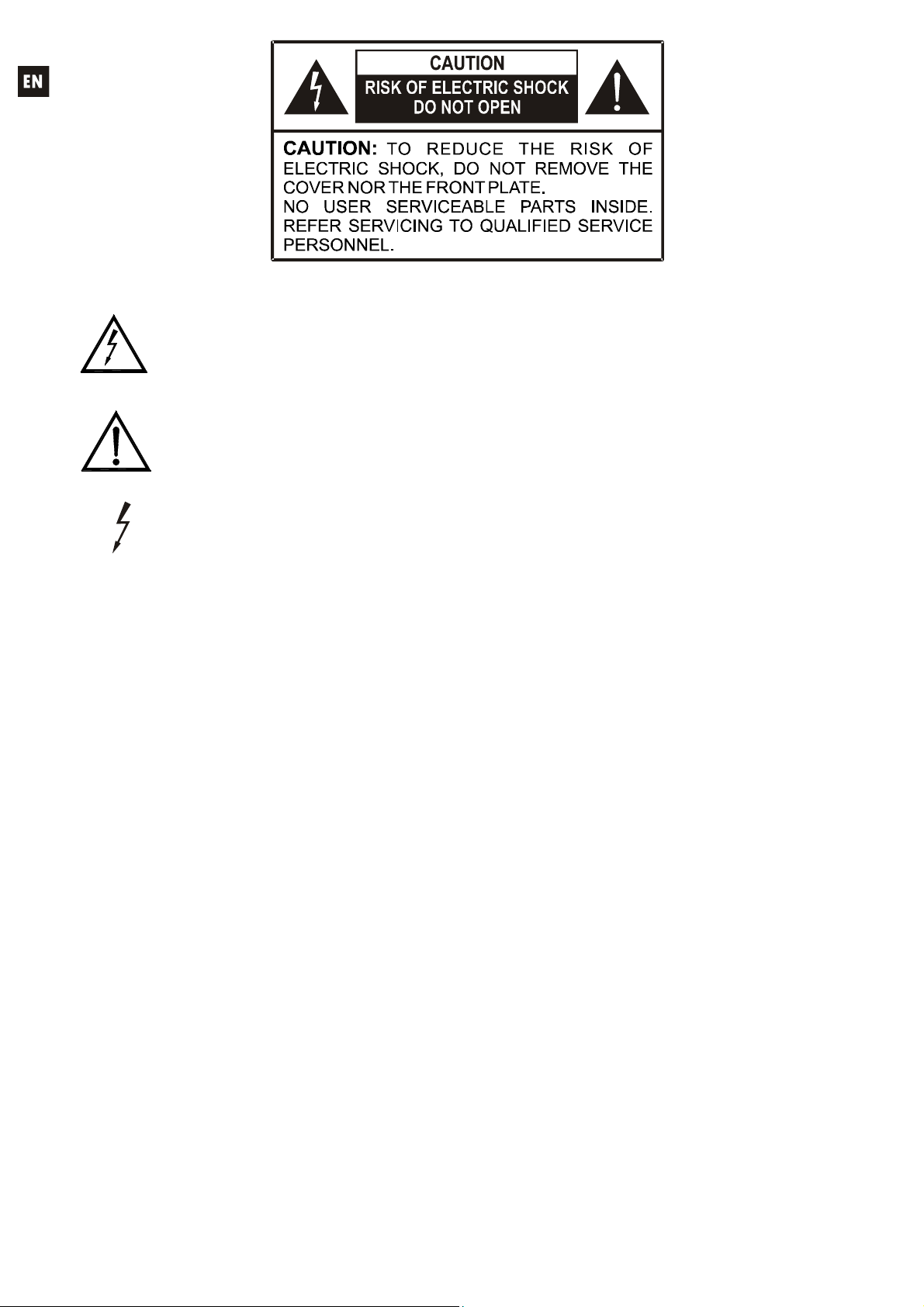
Graphic Symbol Explanation
The lightning flash with arrowhead symbol, within an equilateral triangle, is intended to
alert the user to the presence of uninsulated “dangerous voltage” within the product’s
enclosure that may be of sufficient magnitude to constitute a risk of electric shock to
persons.
The exclamation point within an equilateral triangle is intended to alert the user to the
presence of important operating and maintenance (servicing) instructions in the literature
accompanying the appliance.
The lightning flashes printed next to the OUTPUT terminals of the amplifier are intended
to alert the user to the risk of hazardous energy. Output connectors that could pose a risk
are marked with the lightning flash. Do not touch output terminals while amplifier power is
on. Make all connections with amplifier turned off.
WARNING: To prevent fire or shock hazard, do not expose this equipment to rain or moisture.
IMPORTANT SAFETY INSTRUCTIONS
1. Read these instructions.
2. Keep these instructions.
3. Heed all warnings.
4. Follow all instructions.
5. Do not use this apparatus near water.
6. Clean only with dry cloth.
7. Do not block any ventilation openings. Install in accordance with the manufacturer’s instructions.
8. Do not install near any heat sources such as radiators, heat registers, stoves, or other apparatus
(including amplifiers) that produce heat.
9. Do not defeat the safety purpose of the polarized or grounding type plug. A polarized plug has
two blades with one wider than the other. A grounding type plug has two blades and a third
grounding prong. The wide blade or the third prong are provided for your safety. If the provided
plug does not fit into your outlet, consult an electrician for replacement of the obsolete outlet.
10. Protect the power cord from being walked on or pinched particularly at the plugs, convenience
receptacles, and at the point where they exit from the apparatus.
11. Only use attachments/accessories specified by the manufacturer.
12. Unplug the apparatus during lightening sorts or when unused for long periods of time.
13. Refer all servicing to qualified personnel. Servicing is required when the apparatus has been
damaged in any way, suck as power supply cord or plug is damaged, liquid has been spilled or
objects have fallen into the apparatus, the apparatus has been exposed to rain or moisture, does
not operate normally, or has been dropped.
14. Disconnecting from mains: Switching off the POWER switch (17) all the functions and light
indicators of the amplifier will be stopped, but fully disconnecting the device from mains is done
unplugging the power cord from the mains input socket (15). For this reason, it always shall
remain readily operable.
2
Page 3

USER MANUAL
1. IMPORTANT NOTE 04
1.1. Compliance with international standards 04
2. INTRODUCTION 05
3. INSTALLATION 06
4. FRONT PANEL 07
5. BACK PANEL 09
6. MAIN SCREEN/PRESET MANAGEMENT 10
6.1. RECALL PRESET MENU 10
6.2. SAVE PRESET MENU 11
7. INPUT EDIT MENU 12
8. OUTPUT EDIT MENU 14
9. SETUP MENU 17
10. FRONT PANEL LOCKOUT MENU 19
11. CLEANING 20
12. DIAGRAMS 21
12.1. Function list 21
12.2. Function diagram 21
13. TECHNICAL CHARACTERISTICS 82
All numbers subject to variation due to production tolerances. ECLER S.A. reserves the right to make changes or improvements
in manufacturing or design which may affect specifications.
3
Page 4

1. IMPORTANT NOTE
Congratulations! You have acquired the result of painstaking design and manufacturing. Thank
you for having chosen our ALMA26 processor.
In order to get the optimum operation and efficiency from your product, it is VERY IMPORTANT before you plug anything - to read this manual very carefully and take seriously into account all
considerations specified within it.
We strongly recommend that its maintenance be carried out by our Authorised Technical
Services.
1.1. Compliance with international standards
The ALMA26 processor complies with the following international standards:
EN55103-1 Electromagnetic Compatibility.
Product family standard for audio, video, audio-visual and entertainment lighting control
apparatus for professional use
Part 1: Emission
EN55103-2 Electromagnetic Compatibility.
Product family standard for audio, video, audio-visual and entertainment lighting control
apparatus for professional use
Part 2: Immunity
EN60065 Audio, video and similar electronic apparatus. Safety requirements
Complying with the requirements of directives 73/23/EC and 2004/108/EC
4
Page 5

2. INTRODUCTION
ALMA26 DIGITAL PROCESSOR FOR SPEAKER SYSTEMS
The ALMA26 is a digital signal processor featuring 2 audio inputs and 6 audio outputs, USB
connectivity and two ports of volume remote control (0-10VDC).
Main features
2 audio inputs and 6 audio outputs, with XLR connectors
DSP with 24-bit quantization and 48kHz sampling frequency
2x20 characters LCD display in front panel
4 setup keys + digital rotary encoder to navigate in the menus and set the parameters
1 LED backlit key (MUTE function) for each input and each output (8 in total)
Level meters for each input and each output
2 REMOTE ports to control the volume of the inputs or outputs (0-10VDC) from external devices,
such as WPm series panels
USB interface and compatibility with EclerCOMM software (free download from
http://www.ecler.com/en/products/software.html
)
Processing:
o Controls of gain, phase, MUTE, etc., per input and output
o 4 pEQ (parametric filters) per input/8 pEQ per output
o Butterworth, Bessel or Linkwitz-Riley crossovers on the outputs (up to 48 dB/oct)
o Delays on the inputs and outputs
o Compressor/limiter on the outputs (with make-up gain)
o 3 LINK groups (linking output channels)
System templates for the creation of user setups:
o T1: 3 x 1 stereo way
o T2: 2 stereo ways + 1 stereo way
o T3: 3 stereo ways
o T4: 4 mono ways + 2 mono auxiliaries
o T5: 5 mono ways + 1 mono auxiliary
o T6: 6 mono outputs
Each system template automatically sets the operating and control mode of the channels and
their settings, including the LINK group they pertain to. Example: in a stereo setup, the settings
applied to a left channel output will be automatically applied to the output which is assigned to the
right channel, and vice versa (same LINK group)
User presets: 20
Editing names (labels) of inputs, outputs, presets and device
Two front panel lock modes with password protection (full lock or excluding MUTE keys).
5
Page 6

3. INSTALLATION
The ALMA26 can be mounted in a standard 19” rack (482.6 mm) taking up one height unit
(44 mm).
For professional use it is recommended to place the processor in the same rack as the power
amplifiers.
Given the small power consumption of the unit, no ventilation is required. Nevertheless, it is
advisable not to expose the unit to extreme temperatures as well as ensure a dry and dust-free operating
environment.
It is important not to place the processor next to electrical noise sources such as transformers,
voltage dimmers, motors, etc. or their mains supply cables. The metal cover of the device should never
be removed under any circumstance for that same reason.
The ALMA26 operates with alternate current (AC) between 90 and 264V at 47 to 63Hz. This
device features an oversized power supply which adapts itself to any mains voltage around the world,
without the need of manual adjustment.
Even though the noise produced by powering up is minimum, it is always advisable to follow this
power up sequence: signal sources, mixing unit, processor and, finally, power amplifiers. The power
down sequence must follow exactly a reverse order. By closely following this sequences, all peaks or
transients produced by switching on and off devices do not affect the next devices in the chain and, of
course, never reach the loudspeakers, which are extremely sensitive about this.
Ground Loops
Care should be taken, so that the different mechanical and electrical grounds, as well as the
chassis and ground connections arriving to the device, to be independent from each other.
Ground loops can be easily detected through a low frequency hum noise (50Hz). Depending
on the level of this noise, it can interfere on the music quality.
Audio connections
Usually, many people do not care enough about the quality of cables. Many times, because of a
bad connection or bad quality cables, there can be important problems during the music reproduction.
6
Page 7
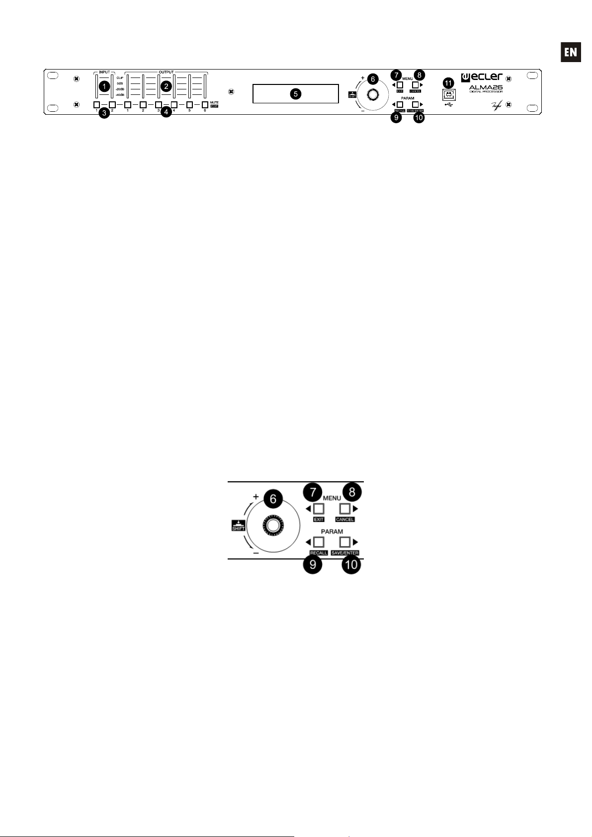
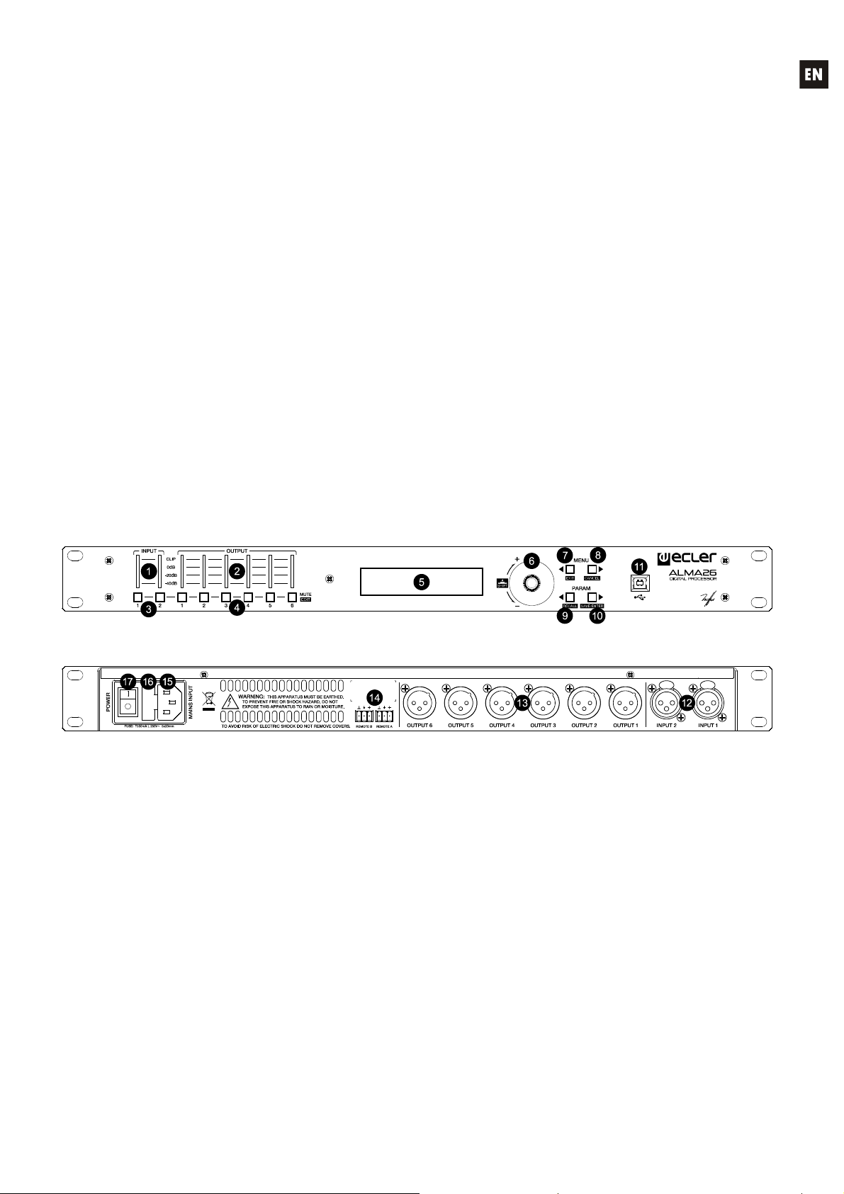
4. FRONT PANEL
Input and output VU meters
Each input (1) or output (2) VU meter allows you to read the level of the audio signal, with 40dB, -
20dB, 0dB and CLIP indications.
MUTE keys
These keys, one for each input (3) or output (4), allow to mute the selected input or output by
pressing them. The LED integrated in the key itself indicates the status of its MUTE function (lit red =
MUTE ON).
LCD display (5)
Display showing numeric data and setup menus, settings and device information.
Encoder-type rotary selector
The rotary selector (6) allows you to modify the value of the parameters displayed on the LCD
screen, by increasing or decreasing them depending on the direction of rotation. The rotary ENCODER
features a push function ("SHIFT") in addition to the rotation function. The SHIFT function allows you to
access advanced setup modes and alternate functions of the four navigation keys of the front panel
(reverse silk-screen printing: EXIT, CANCEL, RECALL and SAVE/ENTER).
Setup keys
The four front panel setup keys allow you to navigate through the various menus and their pages,
and access special features thanks to certain combinations of keys pressed simultaneously:
The left and right MENU keys (7, 8) allow you to scroll through the different pages of the unit's
setup menus.
The left and right PARAM keys (9, 10) allow, within a menu and a page, to select the parameter
whose value has to be modified with the rotary encoder (6): the name of the targeted parameter flashes
in the display while its value can be edited.
7
Page 8

The special combinations of the setup keys are:
Left and right MENU simultaneously for 2 seconds: access to the unit's SETUP menu (see
chapter 9)
Left and right PARAM simultaneously for 2 seconds: access to the unit's front panel
locking/unlocking and password management (see chapter 10)
SHIFT + left MENU (EXIT): bring back to the main screen, from any menu
SHIFT + right MENU (CANCEL): undo the last parameter editing and recall the value as
before the change
SHIFT + left PARAM (RECALL): load one of the presets (device setups) stored in the memory
SHIFT + right PARAM (SAVE/ENTER):
o SAVE: save a preset (device setup) into memory
o ENTER: confirm a critical modification (e.g.: password change)
Right MENU, kept pressed while powering up the unit: load preset #1, designed to be edited
and saved in order to be used as booting setup. This operation is allowed even when the
unit's front panel is locked with a password
Holding down the SHIFT key while powering up the unit: displays the "Power OFF to recover
factory defaults" message. After turning off and on again, default parameters ( factory
defaults) are restored, erasing all user data, settings and presets from the unit's memory
USB Connector
A type-B USB connector (11) is used to connect the ALMA26 to a PC and perform the
unit management and control from EclerCOMM Manager software.
8
Page 9
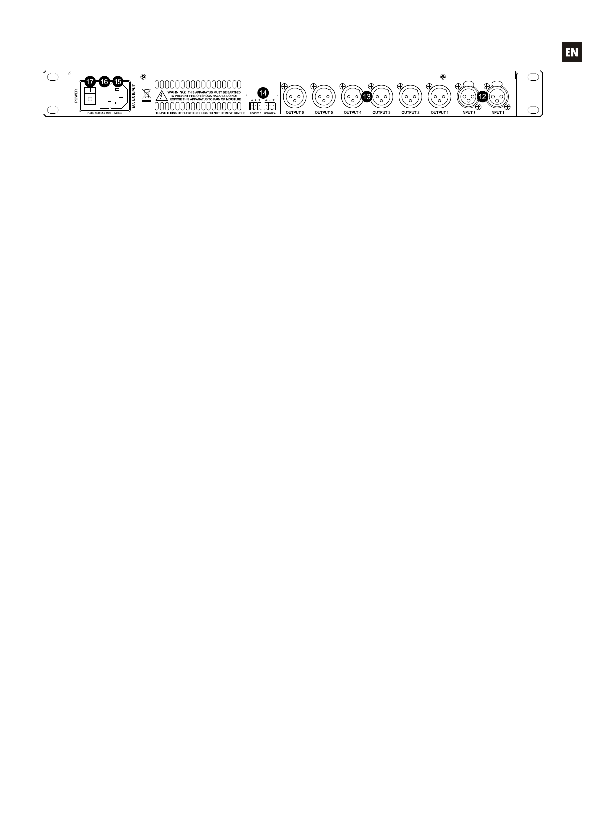
5. BACK PANEL
The back panel features the following connections:
Mains, fuse and power switch (15, 16, 17)
Due to the switched mode power supply, the operating voltage range is 90V – 264V AC, with a
frequency between 47Hz and 63Hz. Before powering up the unit, make sure that the ALMA26 is
correctly connected to ground in a facility that complies with local regulations.
Input (12) and output (13) connectors
The ALMA26 has two balanced audio inputs (CH1 and CH2) on 3-pin female XLR connectors
(pin 1 to ground, pin 2 to signal + (positive) and pin 3 to signal – (negative)). The ALMA26's signal output
is performed through six balanced outputs (OUTPUT1-6), on 3-pin male XLR connectors. As for inputs,
the connectors are configured with the pin 1 to ground, pin 2 to signal + (positive) and pin 3 to signal –
(negative).
REMOTE connectors (14)
The A and B REMOTE connectors allow you to simultaneously control the volume of one or
multiple inputs, or one or multiple outputs through a WPm series wall panel or similar (0-10VDC). The
inputs or outputs controlled through each REMOTE port are selected using the device setup menu (front
keys and LCD display) or from EclerCOMM Manager software.
9
Page 10
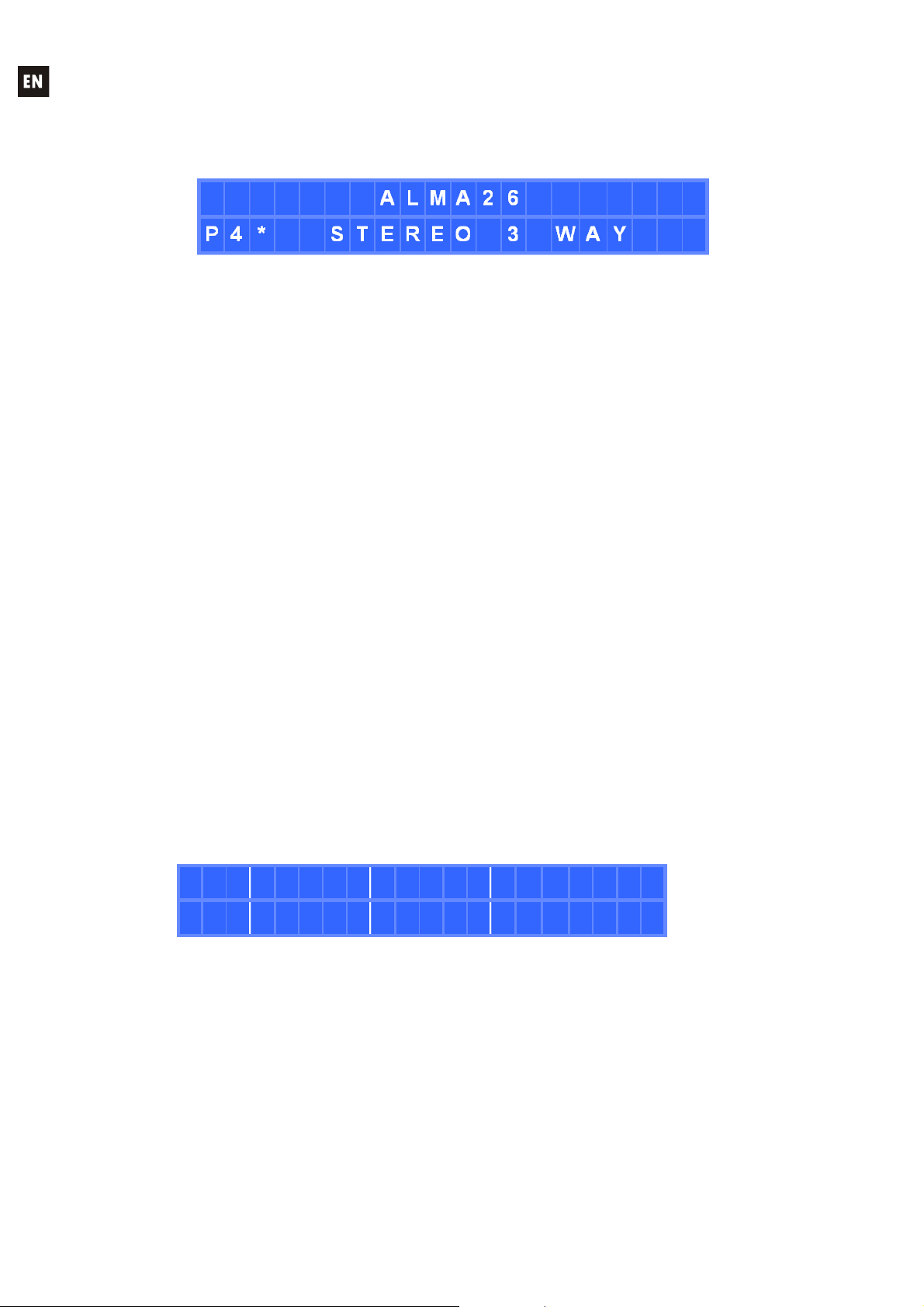
6. MAIN SCREEN/PRESET MANAGEMENT
After powering up the unit, its main screen displays the name or label of the device (default is
ALMA26) on the top line of text. The lower line shows the number and name (LABEL) of the active
preset or template:
An asterisk to the right of the preset number indicates that it has been modified and not yet saved
in the memory of the ALMA26.
6.1. RECALL PRESET MENU
The ALMA26 has 6 operating templates, which are used as a starting point for the configuration
of an operating mode:
o T1: 3 x 1 stereo way
o T2: 2 stereo ways + 1 stereo way
o T3: 3 stereo ways
o T4: 4 mono ways + 2 mono auxiliaries
o T5: 5 mono ways + 1 mono auxiliary
o T6: 6 mono outputs
It is therefore possible to recall one of these templates, to edit its parameters and save the
resulting setup as a PRESET or user memory.
System templates are displayed on the screen with the Txx prefix, where xx is the template
number (between 01 and 06), followed by its name or LABEL. These files are not rewritable.
User presets are displayed on the screen with the Pxx prefix, where xx is the preset number
(between 01 and 20), followed by its name or LABEL. The default name of all user presets is USER
PRESET, but it can be modified when you save one of them in memory.
The procedure for recalling a preset or a user template is the following one:
From the main menu, press SHIFT + RECALL
The RECALL PRESET message is displayed and a preset number is flashing
R E C A L L P R E S E T
[ P 0 4 ] S T E R E O 3 W A Y
Select the preset or template using the rotary control, and then select one of the two
following options:
Press SHIFT + RECALL to validate the selection and activate the new preset, bringing
you back to the main screen, this time with data from the new active preset
Or
Press SHIFT + CANCEL to cancel the selection and display again the preset from the
selection list
Pressing SHIFT + EXIT at any point during the above process cancels the selection and brings
the main screen back.
10
Page 11

6.2. SAVE PRESET MENU
Once you have edited the active preset or template, the procedure to save the current setup in a
user preset memory is the following one:
From the main menu, press SHIFT + SAVE
The SAVE PRESET message is displayed and a preset number is flashing
S A V E P R E S E T
[ P 0 7 ] S T E R E O L I V E 3 W
Select the user preset using the rotary control, and then select one of the two following
options:
Press SHIFT + SAVE to validate the selection
Or
Press SHIFT + CANCEL to cancel the selection and display again the preset from the
selection list
Pressing SHIFT + EXIT at any point during the above process cancels the selection and brings
the main screen back.
If the selection is validated (SHIFT + SAVE) the following screen is displayed, allowing you to
rename the destination preset:
R E N A M E P R E S E T
[ P 0 7 ] S T E R E O L I V E 3 W
To rename the preset:
Press the right PARAM key to select the first character to edit
Edit the new character with the rotary control
Press the left or right PARAM key to select another character to edit
Edit the new character with the rotary control
Etc…
Pressing SHIFT + CANCEL cancels all previous changes, displays the original name and
maintains the edit mode in order to be able to rename the preset again
Once all the desired characters are edited, confirm the changes by pressing SHIFT +
SAVE, displaying the PRESET SAVED message for a few seconds. The preset is stored
in memory, but is not selected as active preset just by the fact of having been saved
The main screen returns, showing again the current preset at the time, and it is not
necessarily the newly saved preset
Pressing SHIFT + EXIT at any point during the above process cancels the selection and brings
the main screen back.
The parameters stored in a preset are:
All the input and output settings, including their names (labels)
The A and B REMOTE ports setup
The internal signal generator setup
11
Page 12

7. INPUT EDIT MENU
To open the edit menu for the settings of an input, you have to press SHIFT + MUTEx, MUTEx
being the input 1 or 2 MUTE key.
Once in the edit menu for an input, and in one of its pages, it is possible to obtain the same page
for the other input by pressing SHIFT + MUTEx, MUTEx being the input 2 MUTE key if you were editing
the input 1, or 1 if you were editing the input 2.
The new edited values are activated in real time. You can cancel an edit operation, bringing back
the value before editing, by pressing SHIFT + CANCEL.
To exit the Edit menu and return to the main screen:
Press SHIFT + EXIT
Press SHIFT + MUTEx (the MUTE key of the input x currently edited)
Stay 2 minutes without operating any control on the front panel
The next page shows the full structure and options of the menu for setting inputs.
NOTES:
1. In the setting pages of the 4 parametric filters available for each input, the displayed
abbreviations meaning is:
BYP: BYPASS (filter not activated)
PEQ: PARAMETRIC EQ
HS6 / HS12: HIGH SHELF 6 or 12 dB/octave
LS6 / LS12: LOW SHELF 6 or 12 dB/octave
HP6 / HP12: HIGH PASS 6 or 12 dB/octave
LP6 / LP12: LOW PASS 6 or 12 dB/octave
AP1 / AP2: ALL PASS 1st or 2nd order
2. The COPY FROM – PASTE TO operation copies all the settings from the source input to the
destination input, except for its name (LABEL)
12
Page 13
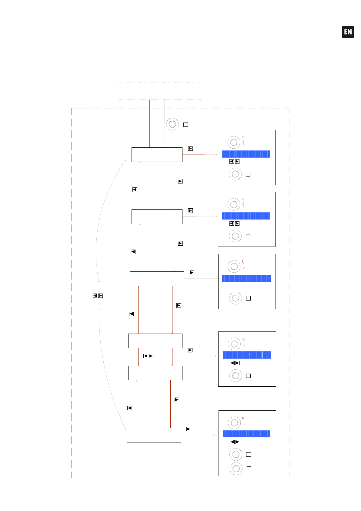
FrontpanelInputssetup
/ get
/ get
/ get
/ get
/ get
ge
To edit an INPUT setup, press & hold SHIFT (front knob press)
the IN1 or IN2 MUTE key. You will then enter into the INPUTs setup
Once in the setup mode of an input, press SHIFT + INx MUTE key to move to
Press SHIFT + EXIT or wait 2 minutes to exit the setup
current setup menu of the new INx
ALMA26 main screen
INx setup mode
(x = 1 or 2)
Move to the
previous
Move to the
previous
MENU
Move to next
previous
MENU
Move to the
previous
MENU
INPUT LABEL
MENU
GAIN - PHASE -
DELAY
EQUALIZER
ON/OFF
SHIF
INx MUTE
+
MUT
MENU
MENU
MENU
PARA
Move to the
next
menu
PARA
Move to the
next
menu
PARA
Move to the
next
Select the
character to edit
Select the
parameter to edit
Select the
parameter to edit
Rotate knob
to change
character
I N P U T L A B E L
[ L E F T S T E R E O ]
G A I N d B P H A S E D L Y c m
- 9 8 . 6 N E G 1 0 6 8 0
Select
new
character to edit
+
CANCE
Rotate knob
to change
valu
Select
new
parameter to edit
+
CANCE
Rotate knob
to change
valu
+
CANCE
Cancel
text
Cancel
valu
Cancel
valu
PARA
SHIF
PARA
SHIF
E Q U A L I Z E R
O F F
SHIF
Move to the
previous
EQ FILTERS
EQ FILTERS
MENU
COPY FROM
PASTE TO
EQ1
MENU
EQ4
Move to the
next /
EQ
MENU
PARA
Move to the
next
PARA
Select the
parameter to edit
Select the
parameter to edit
E Q 1 F R E Q G A I N Q
H S 1 2 3 . 1 6 k - 1 2 . 3 1 2 5
C O P Y F R O M P A S T E T O
I N 2 I N 1
PARA
SHIF
PARA
SHIF
SHIF
Rotate knob
to change
valu
Select
parameter to edit
Cancel
+
CANCE
Rotate knob
to chan
valu
Select
parameter to edit
Cancel
+
CANCE
Confirm Copy /
+
SAVE
valu
valu
Paste
operation
13
Page 14

8. OUTPUT EDIT MENU
To open the edit menu for the settings of an output, you have to press SHIFT + MUTEx, MUTEx
being the output 1 to 6 MUTE key.
Once in the edit menu for an output, and in one of its pages, it is possible to obtain the same
page for another output by pressing SHIFT + MUTEx, MUTEx being the MUTE key for the other output.
The new edited values are activated in real time. You can cancel an edit operation, bringing back
the value before editing, by pressing SHIFT + CANCEL.
To exit the Edit menu and return to the main screen:
Press SHIFT + EXIT
Press SHIFT + MUTEx (the MUTE key of the output x currently edited)
Stay 2 minutes without operating any control on the front panel
The next page shows the full structure and options of the menu for setting outputs.
NOTES:
1. In the setting pages of the 8 parametric filters available for each output, the displayed
abbreviations meaning is:
BYP: BYPASS (filter not activated)
PEQ: PARAMETRIC EQ
HS6 / HS12: HIGH SHELF 6 or 12 dB/octave
LS6 / LS12: LOW SHELF 6 or 12 dB/octave
HP6 / HP12: HIGH PASS 6 or 12 dB/octave
LP6 / LP12: LOW PASS 6 or 12 dB/octave
AP1 / AP2: ALL PASS 1st or 2nd order
2. In the setting pages of the Hi-Pass and Low-Pass crossover filters available for each output,
the displayed abbreviations meaning is:
BYP: BYPASS (filter not activated)
BES12, 18, 24, 48: BESSEL-type filter, 12, 18, 24 or 48 dB/octave
BUT6, 12, 18, 24, 48: BUTTERWORTH -type filter, 6, 12, 18, 24 or 48 dB/octave
LR12, 24, 48: LINKWITZ-RILEY-type filter, 12, 24 or 48 dB/octave
3. The COPY FROM – PASTE TO operation copies all the settings from the source output to the
destination output, except for its source selection (SOURCES) and its name (LABEL)
14
Page 15
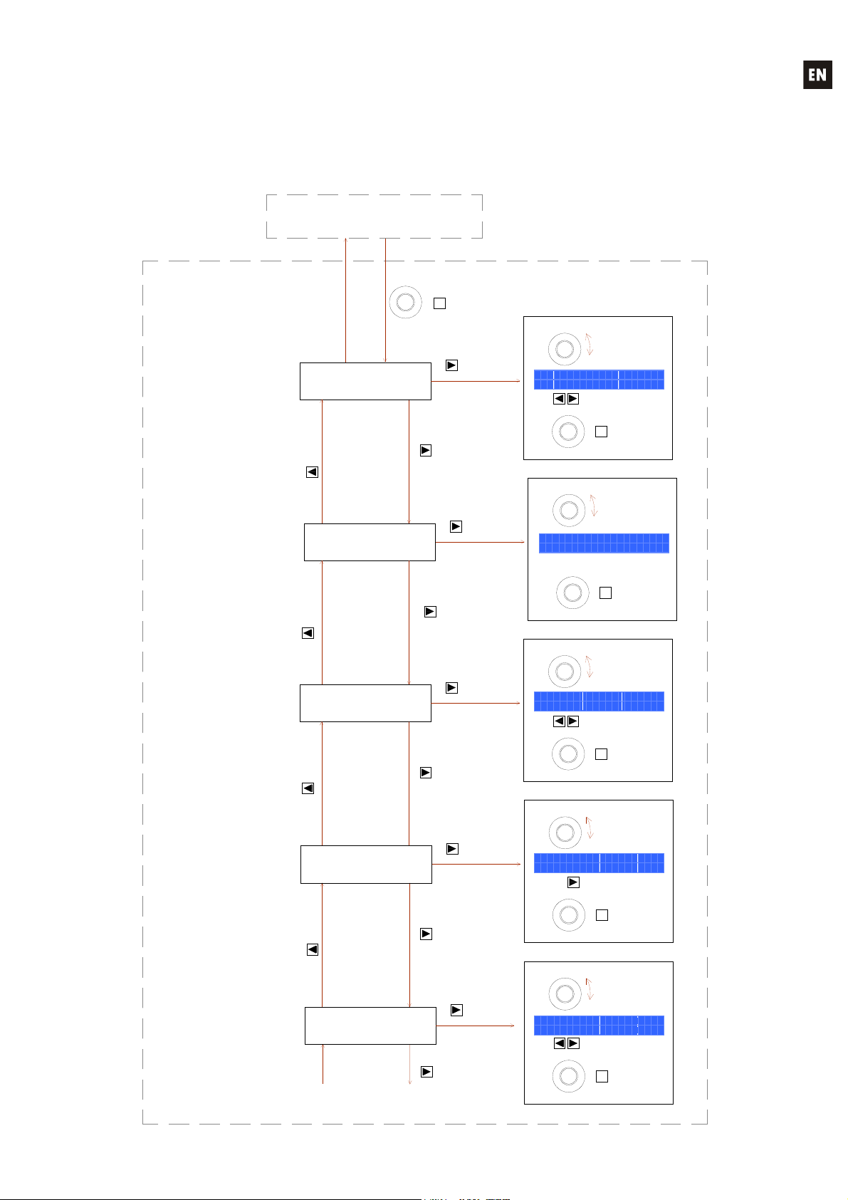
FrontpanelOUTPUTSsetup
To edit an OUTPUT setup, press & hold SHIFT (front knob press) and
You will then enter into the OUTPUTs setup menu.
Press SHIFT + EXIT or wait 2 minutes to exit the setup mode.
Once in the setup mode of an output, press SHIFT + OUTx MUTE key to move to the
current setup menu of the new OUTx output.
an OUT1 to OUT6 MUTE key
ALMA26 main screen
OUTx setup mode
(x = 1, 3, 3, 4, 5 or 6)
OUTPUT LABEL
Move to the
previous menu
Move to the
previous menu
MENU
MENU
GAIN - PHASE -
Move to the
previous menu
MENU
CROSSOVER
Move to the
previous menu
MENU
Continues in next
SHIFT
SOURCE
DELAY
LOW PASS
CROSSOVER
HIGH PASS
diagram...
OUTx MUTE key
+
MUTE
MENU
MENU
MENU
MENU
MENU
character to edit
PARAM
Move to the
next menu
PARAM
Move to the
next menu
parameter to edit
PARAM
Move to the
next menu
character to edit
PARAM
Move to the
next menu
PARAM
Move to the
next menu
Select the first
Select the first
parameter to edit
Select the first
Select the first
Select the first
parameter to edit
Rotate knob
to change
character
O U T P U T L A B E L
[ L E F T S U B - B A S S ]
G A I N d B P H A S E D L Y c m
- 9 8 . 6 N E G 1 0 6 8 0
X O V E R L P F R E Q
B E S 1 2 3 . 1 6 k H z
X O V E R H P F R E Q
B U T 2 4 1 4 . 6 k H z
Select new
character to edit
PARAM
SHIFT
+
CANCEL
Rotate knob
S O U R C E
I N 1 + 2
SHIFT
+
CANCEL
Rotate knob
to change
Select new
parameter to edit
PARAM
SHIFT
+
CANCEL
Rotate knob
to change
Select new
parameter to edit
PARAM
SHIFT
+
CANCEL
Rotate knob
to change
Select new
parameter to edit
PARAM
SHIFT
+
CANCEL
Cancel edition
/ get previous
to change
value
Cancel edition
/ get previous
value
Cancel edition
/ get previous
value
Cancel edition
/ get previous
value
Cancel edition
/ get previous
text
value
value
value
value
15
Page 16
Move to the
previous menu
From previous diagram...
MENU
MENU
EQUALIZER
ON / OFF
Move to the
next menu
PARAM
Select the first
parameter to edit
Rotate knob
to change
value
E Q U A L I Z E R
O F F
Cancel edition
+
/ get previous
CANCEL
Rotate knob
to change
value
Select new
parameter to edit
Cancel edition
+
/ get previous
CANCEL
Rotate knob
to change
value
Select new
parameter to edit
Cancel edition
+
/ get previous
CANCEL
Rotate knob
to change
value
Select new
parameter to edit
Cancel edition
+
/ get previous
CANCEL
Confirm Copy /
+
SAVE
value
value
value
value
Paste
operation
Move to the
previous menu
Move to the
previous menu
previous menu
Move to the
previous menu
MENU
EQ FILTERS
MENU
EQ FILTERS
MENU
COMPRESSOR /
LIMITER
Move to the
MENU
COPY FROM
PASTE TO
MENU
EQ1
next / previous
EQ8
Move to the
EQ filter
MENU
MENU
MENU
Move to the
next menu
PARAM
PARAM
Move to the
next menu
PARAM
Move to the
next menu
Select the first
parameter to edit
Select the first
parameter to edit
Select the first
parameter to edit
SHIFT
E Q 1 F R E Q G A I N Q
H S 1 2 3 . 1 6 k - 1 2 . 3 1 2 5
PARAM
SHIFT
C O M P R E S / L I M R A T I O
O F F i n f : 1
T H R E S H O L D K N E E
T H R E S H O L D K N E E
- 2 6 . 2 d B S O F T
- 2 6 . 2 d B S O F T
A T T A C K R E L E A S M A K E U P
4 3 6 m s 1 . 6 m s 6 . 7 d B
PARAM
SHIFT
C O P Y F R O M P A S T E T O
O U T 2 O U T 4
PARAM
SHIFT
SHIFT
16
Page 17

9. SETUP MENU
The ALMA26 offers a general setup menu (hereinafter SETUP menu), with parameters that
globally affect the unit, such as unit name, internal signal generator, functions assigned to the REMOTE
ports, etc.
To open the SETUP menu you have to simultaneously press and hold down the left and right
MENU keys.
The new edited values are activated in real time. You can cancel an edit operation, bringing back
the value before editing, by pressing SHIFT + CANCEL.
To exit the Edit menu and return to the main screen:
Press SHIFT + EXIT
Stay 2 minutes without operating any control on the front panel
The next page shows the full structure and options of the SETUP menu.
NOTES:
1. In the assignation page of the REMOTE 1 or REMOTE 2 ports to the volume control of inputs
or outputs, the signs displayed under the number of an input or output have the following
meanings:
Blank = Input or output not assigned to any remote port
● = Remote port assigned to the input or output
X = Input or output already assigned to the other remote port
2. In the internal signal generator page, the displayed abbreviations meaning is:
PINK N. : Pink noise
WHITE N. : White noise
SINEWAVE : Sinusoidal signal, with adjustable frequency
POLARITY : Polarity check signal, with adjustable frequency
17
Page 18
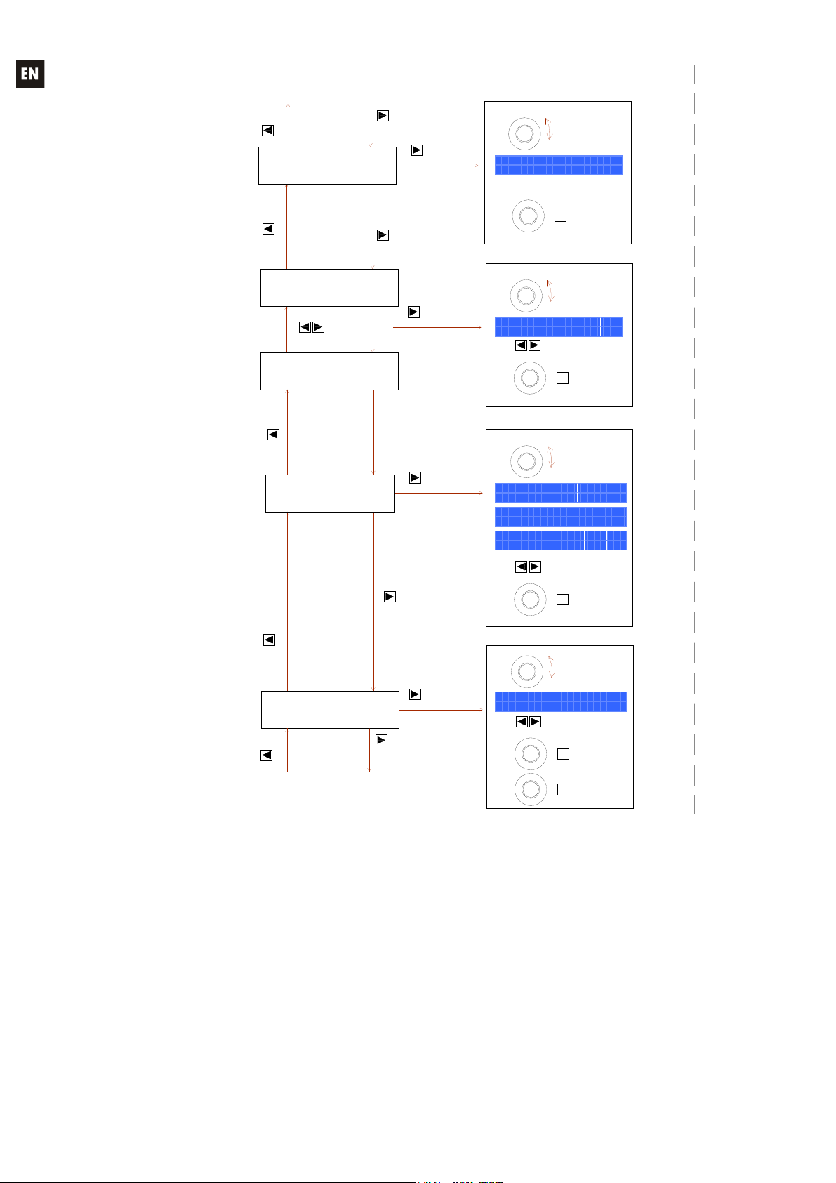
SETUPsetup
To enter SETUP menu press & hold MENU left & right front keys.
Press SHIFT + EXIT or wait 2 minutes to exit the setup mode.
ALMA26 main screen
SETUP menu
Move to the
previous menu
Move to the
previous menu
Move to next /
previous menu
MENU
Move to the
previous menu
DEVICE LABEL
MENU
GENERATOR
MENU
REMOTE 1
next / previous
MENU
REMOTE 2
MENU
Move to the
REMOTE
Press & Hold
+
MENU
MENU
MENU
CANCEL
MENU
both keys
character to edit
PARAM
Move to the
next menu
parameter to edit
PARAM
Move to the
next menu
PARAM
Move to the
next menu
Select the first
Select the first
Select the first
parameter to edit
Rotate knob
to change
character
D E V I C E L A B E L
[ A L M A 2 6 ]
G E N E R A T O R F R E Q
S I N E W A V E 1 0 0 H z
R E M O T E 1 1 2 3 4 5 6
O U T P U T S o o
R E M O T E 2 1 2
I N P U T S x o
PARAM
SHIFT
PARAM
SHIFT
PARAM
SHIFT
Select new
character to edit
Cancel editio n
+
/ get previous
CANCEL
Rotate knob
to change
value
Select new
parameter to edit
Cancel editio n
+
/ get previous
CANCEL
Rotate knob
to change
value
Select new
parameter to edit
Cancel edition
+
/ get previous
CANCEL
Rotate knob
to change
value
text
value
value
EXIT
18
Move to the
previous menu
Move to the
previous menu
LCD CONTRAST
MENU
DELAY UNITS
MENU
FIRMWARE
VERSION
MENU
Move to the
next menu
L C D C O N T R A S T
1 0 0
+
+
CANCEL
CANCEL
Cancel edition
/ get previous
Rotate knob
to change
value
Cancel edition
/ get previous
value
value
SHIFT
D E L A Y U N I T
m i l l i s e c o n d s
SHIFT
F I R M W A R E V E R S I O N
v 0 1 . 0 3 r 1 2
Page 19

10. FRONT PANEL LOCKOUT MENU
The ALMA26 has a front panel lockout feature, protecting the unauthorized access to the device
with a password.
The locking feature has three operating modes:
UNLOCK ALL: Lock function disabled, allowing access to all functions and menus of the
equipment
LOCK ALL: the lock is enabled, until an alphanumeric password is entered. The front panel
controls are disabled, needing access to the lock menu to enter the password and re-enable
them.
UNLOCK MUTE: the lock is enabled, until an alphanumeric password is entered. The front
panel controls are disabled, except the MUTE keys for inputs and outputs, needing access to
the lock menu to enter the password and re-enable them.
To access the lock menu, you have to press simultaneously the left and right PARAM keys for 2
seconds, until the next screen appears on the LCD display:
L O C K M O D E
U N L O C K M U T E
Using the rotary control, it is possible to change the desired locking mode and then press SHIFT
+ ENTER to confirm the selection. If you select one of the two password protected modes (LOCK ALL or
UNLOCK MUTE), the next screen prompts you to enter the lock password:
T Y P E P A S S W O R D
[ E C L E R ]
Using the rotary control, edit the selected character, and using the PARAM keys, select the next
character to edit. Finally, press SHIFT + ENTER to validate the entered password.
In the password edit mode, you can cancel an edit operation, bringing the initial password back,
by pressing SHIFT + CANCEL. Pressing SHIFT + CANCEL for five seconds erases all the characters of
the password, to start the edition from scratch.
At any time it is possible to leave the lock menu by pressing SHIFT + EXIT.
Once in one of the password protected locking modes (LOCK ALL or UNLOCK MUTE), the
equipment displays the following screen if you press any disabled front panel control:
P A N E L L O C K E D
To re-enable the front panel controls, it is necessary to enter the stored password. To do this,
access the lock menu (left and right PARAM keys simultaneously for 2 seconds). The following screen is
displayed:
19
Page 20

P A S S W O R D R E Q U I R E D
[ * ]
Enter the password and press SHIFT + ENTER to validate it.
P A N E L U N L O C K E D
The equipment will be temporarily unlocked, until it remains 2 minutes without any activity on the
front panel or returns to the lock menus (left and right PARAM simultaneously for 2 seconds) to confirm
or modify the lock mode, in which case it will go back to the password request (the same or a new one),
which will be active starting from your validation (SHIFT + ENTER).
To permanently unlock the equipment, access the lock menu and select the UNLOCK ALL mode
as new locking mode.
11. CLEANING
The control panel must not be cleaned with any dissolvent, abrasive or petroleum derived
substance else paint and silk-printing could be damaged. Whenever cleaning should be necessary use a
soft cloth slightly wet with water and neutral liquid soap. Be careful that no liquid gets into the unit
through its orifices. Never use sharp or erosive objects to scratch the control panel.
20
Page 21
12. DIAGRAMS
12.1. Function list
1. LED VU-Meter, INPUTS
2. LED VU-Meter, OUTPUTS
3. Mute keys, INPUTS
4. Mute keys, OUTPUTS
5. Front panel LCD display
6. Rotary encoder knob
7. Setup key, MENU / EXIT
8. Setup key, MENU / CANCEL
9. Setup key, PARAM / RECALL
10. Setup key, PARAM / SAVE/ENTER
11. USB connector
12. XLR input connectors
13. XLR output connectors
14. Screwable terminals for remote control, REMOTE
15. Mains socket
16. Fuse holder
17. Power switch
12.2. Function diagram
21
Page 22

Explicación de los Símbolos Gráficos
El símbolo del relámpago con una flecha en la punta y dentro de un triangulo equilátero,
tiene el propósito de alertar al usuario de la presencia de un voltaje peligroso y sin aislar
dentro del aparato, y de una magnitud tal que puede constituir riesgo de descarga
eléctrica para las personas.
El símbolo de exclamación dentro de un triangulo equilátero, tiene el propósito de alertar
al usuario de la presencia de instrucciones importantes sobre la operación y
mantenimiento en la información que viene con el producto.
Los símbolos de relámpagos dibujados cerca de los terminales de salida se utilizan para
alertar al usuario del riesgo de descargas peligrosas. Los conectores de salida que
podrían plantear algún riesgo se indican con este símbolo del relámpago. No toque los
terminales de salida mientras que el amplificador esté encendido. Hacer todas las
conexiones con el amplificador apagado.
ADVERTENCIA: para prevenir choques eléctricos o riesgo de incendios, no exponer este equipo a la
lluvia o la humedad.
INSTRUCCIONES IMPORTANTES DE SEGURIDAD
1. Lea estas instrucciones
2. Guarde estas instrucciones
3. Preste atención a todas las advertencias
4. Siga todas las instrucciones
5. No utilice este aparato cerca del agua
6. Límpielo solamente con un paño seco
7. No bloquee ninguna abertura para ventilación. Instálelo de acuerdo con las instrucciones del
fabricante
8. No lo instale cerca de fuentes de calor como radiadores, estufas u otros aparatos que produzcan
calor, incluidos amplificadores.
9. No elimine el propósito de seguridad del cable de corriente polarizado o con conexión de tierra.
Un cable polarizado tiene dos bornes, uno más ancho que el otro. Un enchufe con conexión a
tierra, tiene dos bornes y un tercer borne conectado a tierra. Este tercer borne está previsto para
su seguridad. Si el cable proporcionado no entra en su enchufe, consulte con un técnico
electricista para reemplazar ese enchufe obsoleto.
10. Proteja el cable eléctrico de ser aplastado, en especial en la zona de los conectores, los
receptáculos de los mismos y en el punto en el que el cable sale del aparato.
11. Utilice solamente los accesorios especificados por el fabricante.
12. Desconecte el aparato durante las tormentas eléctricas o cuando no lo vaya a usar durante
periodos largos de tiempo.
13. Para cualquier reparación, póngase en contacto con un servicio técnico cualificado. La
reparación es necesaria cuando el aparato no funciona con normalidad o ha sido dañado por
cualquier motivo, ya sea porque el cable o el enchufe estén dañados, porque se hayan
derramado líquidos o hayan caído objetos dentro del aparato, o porque el aparato haya sido
expuesto a la lluvia o se haya caído.
14. Desconexión de la red: apagando el interruptor de POWER (17) todas las funciones e
indicadores del amplificador se pararán, pero la completa desconexión del aparato se consigue
desconectando el cable de red de su conector (15). Por esta razón, éste siempre debe tener fácil
acceso.
22
Page 23

MANUAL DE INSTRUCCIONES
1. NOTA IMPORTANTE 24
1.1. Conformidad con normativas internacionales 24
2. INTRODUCCIÓN 25
3. INSTALACIÓN 26
4. PANEL FRONTAL 27
5. PANEL POSTERIOR 29
6. PANTALLA PRINCIPAL / GESTIÓN DE PRESETS 30
6.1. MENÚ RECALL PRESET 30
6.2. MENÚ SAVE PRESET 31
7. MENÚ EDICIÓN DE ENTRADAS 32
8. MENÚ EDICIÓN DE SALIDAS 34
9. MENÚ DE CONFIGURACIÓN (SETUP) 37
10. MENÚ DE BLOQUEO DEL PANEL FRONTAL 39
11. LIMPIEZA 40
12. DIAGRAMAS 41
12.1. Lista de funciones 41
12.2. Diagrama de funciones 41
13. CARACTERÍSTICAS TÉCNICAS 82
Todos los datos están sujetos a variación debida a tolerancias de producción. ECLER S.A. se reserva el derecho de realizar
cambios o mejoras en la fabricación o diseño que pudieran afectar las especificaciones.
23
Page 24

1. NOTA IMPORTANTE
¡Enhorabuena!. Vd. posee el resultado de un cuidadoso diseño y una esmerada fabricación.
Agradecemos su confianza por haber elegido nuestro procesador ALMA26.
Para conseguir la máxima operatividad del aparato y su máximo rendimiento es MUY
IMPORTANTE, antes de su conexión, leer detenidamente y tener muy presentes las consideraciones
que se especifican en este manual.
Para garantizar el óptimo funcionamiento de este aparato, recomendamos que su mantenimiento
sea llevado a cabo por nuestros Servicios Técnicos autorizados.
1.1. Conformidad con normativas internacionales
El procesador ALMA26 está conforme a las siguientes normativas internacionales:
EN55103-1 Compatibilidad Electromagnética.
Norma de familia de Productos para aparatos de uso profesional de sonido, vídeo, sistemas
audiovisuales y para el control de iluminación para espectáculos
Parte 1: Emisión
EN55103-2 Compatibilidad Electromagnética.
Norma de familia de Productos para aparatos de uso profesional de sonido, vídeo, sistemas
audiovisuales y para el control de iluminación para espectáculos
Parte 2: Inmunidad
EN60065 Aparatos de audio, vídeo y aparatos análogos. Requisitos de seguridad
Cumpliendo los requisitos de las directrices 73/23/CEE y 2004/108/CE
24
Page 25

2. INTRODUCCIÓN
PROCESADOR DIGITAL PARA SISTEMAS DE ALTAVOCES ALMA26
El ALMA26 es un procesador digital de señal dotado de 2 entradas y 6 salidas de audio,
conectividad USB y dos puertos de control de volumen remoto (0-10VDC).
Características principales
2 entradas y 6 salidas de audio, conectores XLR
DSP con cuantización en 24 bits y frecuencia de muestreo de 48kHz
Display LCD 2x20 caracteres en panel frontal
4 teclas de configuración + encoder rotatorio digital para la navegación por menús y ajuste de
parámetros
1 tecla retroiluminada LED (función MUTE) para cada entrada y cada salida (8 en total)
Vúmetros de medición para cada entrada y cada salida
2 puertos REMOTE para el control de volumen de entradas o salidas (0-10 VDC) mediante
dispositivos externos, como los paneles de la serie WPm
Interface USB y compatibilidad con software EclerCOMM (descarga gratuita desde
http://www.ecler.com/en/products/software.html
)
Procesamiento:
o Controles de ganancia, fase, MUTE, etc. por entrada y salida
o 4 pEQ (filtros paramétricos) por entrada / 8 pEQ por salida
o Crossovers Butterworth, Linkwitz-Riley o Bessel en salidas (hasta 48 dB / oct)
o Delay en entradas y en salidas
o Compresor / limitador en salidas (con make-up gain)
o 3 grupos de LINK (enlace de canales de salida)
Plantillas del sistema para la creación de configuraciones de usuario:
o T1: 3 x 1 vía estéreo
o T2: 2 vías estéreo + 1 vía estéreo
o T3: 3 vías estéreo
o T4: 4 vías mono + 2 auxiliares mono
o T5: 5 vías mono + 1 auxiliar mono
o T6: 6 salidas mono
Cada plantilla del sistema define de forma automática el modo de trabajo y control de los canales
y sus ajustes, incluyendo en que grupo de LINK se encuentran. Ejemplo: en una configuración
estéreo, los ajustes aplicados a una salida del canal izquierdo se aplicarán automáticamente a la
salida asignada al canal derecho, y viceversa (mismo grupo LINK)
Presets de usuario: 20
Edición de nombres (labels) de entradas, salidas, presets y dispositivo
Dos modos de bloqueo del panel frontal con protección mediante contraseña (total o bien con
excepción de las teclas de MUTE)
25
Page 26

3. INSTALACIÓN
El ALMA26 puede montarse en un rack estándar de 19" (482.6mm) ocupando una unidad rack
de altura (44mm). Este aparato debe ser conectado a tierra mediante su cable de alimentación.
En instalaciones profesionales se ubicará preferentemente en el mismo rack donde estén
situados los amplificadores de potencia.
Ya que el consumo es muy bajo, no precisa ventilación, sin embargo, debe evitarse que esté
expuesto a una temperatura extrema y debe procurarse que la atmósfera en que esté emplazado sea lo
más seca y limpia de polvo posible.
Es importante no situarlo cerca de fuentes de ruido, tales como transformadores, variadores de
tensión, motores, etc., así como de los cables de alimentación de estos. Por esta misma razón y bajo
ninguna circunstancia deben quitarse las tapas metálicas del aparato.
El ALMA26 funciona con tensión alterna de 90 a 264V y 47 a 63Hz. Este aparato equipa una
fuente de alimentación sobredimensionada capaz de adaptarse sin ningún tipo de ajuste a la tensión de
red de cualquier país del mundo.
Aunque el ruido producido por la puesta en funcionamiento es mínimo, siempre resulta muy
recomendable poner en marcha los aparatos siguiendo el recorrido de la señal: fuentes de sonido, unidad
de mezclas, procesador y finalmente amplificadores de potencia. El paro de los aparatos debe realizarse
en la secuencia inversa. Siguiendo este orden, los picos o transitorios producidos por el encendido o
apagado de los aparatos no afecta a los siguientes, y por consiguiente tampoco llegan a los altavoces,
elementos extremadamente susceptibles de averiarse en estos casos.
Bucles de masa
Procuraremos que las masas mecánicas y eléctricas, chasis y conexiones, que llegan al aparato
sean independientes.
La formación de bucles de masa se detecta por un zumbido de baja frecuencia (50Hz). Estos
zumbidos según nivel pueden llegar a interferir en la calidad de la reproducción sonora.
Conexiones de audio
Normalmente a los cables y conectores no se les presta el interés merecido. En muchas ocasiones,
y debido a una mala conexión o por el uso de cables de baja calidad, pueden aparecer importantes
problemas en la reproducción sonora.
26
Page 27

4. PANEL FRONTAL
Vu-metros de entrada y salida
El Vu-metro de cada entrada (1) o cada salida (2) permite visualizar el nivel de la señal de audio
de entrada, con indicación de -40dB, -20dB, 0 dB y CLIP.
Teclas de MUTE
Estos botones, uno para cada una de las entradas (3) y salidas (4), permiten silenciar la entrada
o la salida seleccionada mediante su pulsación. El indicador LED integrado en la propia tecla indica el
estado de su función MUTE (encendido en rojo = MUTE ON).
Pantalla LCD (5)
Pantalla en la que se visualizan todos los datos numéricos y de texto de los menús de
configuración, ajuste e información de dispositivo.
Selector rotativo tipo "ENCODER"
El selector rotativo (6) permite modificar el valor del los parámetros visualizados en la pantalla
LCD, incrementando o disminuyendo los mismos en función del sentido de giro. El ENCODER rotativo
dispone, además de la función de giro, de una función de pulsación o “SHIFT”. La función SHIFT
permite acceder a modos de configuración avanzados y a las funciones alternativas de las cuatro teclas
de navegación del panel frontal, impresas en serigrafía inversa (EXIT, CANCEL, RECALL y
SAVE/ENTER).
Teclas de configuración
Las cuatro teclas de configuración del panel frontal permiten navegar por los diferentes menús y
sus páginas, y acceder a funciones especiales gracias a determinadas combinaciones de teclas
pulsadas simultáneamente:
Las teclas MENU derecha e izquierda (7, 8) permiten desplazarse por las diferentes páginas de
los menús de configuración del equipo.
Las teclas PARAM derecha e izquierda (9, 10) permiten, dentro de un menú y una página,
seleccionar el parámetro cuyo valor se desea modificar mediante el encoder rotatorio (6): el nombre del
parámetro objeto de edición parpadea en pantalla mientras su valor está sujeto a los cambios.
27
Page 28

Las combinaciones especiales de las teclas de configuración son:
MENU derecha e izquierda simultáneamente, durante 2 segundos: acceso al menú de
configuración del equipo o menú SETUP (ver capítulo 9)
PARAM derecha e izquierda simultáneamente, durante 2 segundos: acceso al bloqueo /
desbloqueo del panel frontal del equipo y gestión de contraseñas (ver capítulo 10)
SHIFT + MENU izquierda (EXIT): regresar a la pantalla principal, desde un menú cualquiera
SHIFT + MENU derecha (CANCEL): deshacer la última edición de parámetro y recuperar el
valor anterior al cambio
SHIFT + PARAM izquierda (RECALL): cargar uno de los presets (configuraciones del equipo)
guardados en memoria
SHIFT + PARAM derecha (SAVE/ENTER):
o SAVE: guardar en memoria un preset (configuración del equipo)
o ENTER: confirmar una modificación crítica (ej.: cambio de contraseña)
MENU derecha, pulsado y mantenido mientras se enciende el equipo: cargar el preset 1,
concebido para ser editado y guardado previamente para emplearse como configuración de
arranque. Esta operación está permitida incluso cuando el panel frontal del equipo se
encuentra bloqueado mediante contraseña
SHIFT pulsado y mantenido mientras se enciende el equipo: muestra el mensaje “Power OFF
to recover factory defaults”. Tras el apagado y encendido de nuevo, se produce una
restauración de los parámetros por defecto (factory defaults), borrando todos los datos de
usuario, ajustes y presets de la memoria del equipo
Conector USB
Se dispone de un conector USB tipo B (11), que se utiliza para conectar el ALMA26
con un PC y realizar así la gestión y control del equipo mediante la aplicación software
EclerCOMM Manager.
28
Page 29

5. PANEL POSTERIOR
El panel posterior dispone de las conexiones siguientes:
Base de red, fusible y tecla de encendido (15, 16, 17)
Al disponer de fuente de alimentación conmutada, los márgenes de tensión de funcionamiento
van de 90V a 264V AC, a una frecuencia entre 47 a 63Hz. Antes de arrancar la unidad, deberemos
asegurarnos que el ALMA26 esté correctamente conectado a tierra y en una instalación que cumpla con
las normas locales.
Conectores de Entrada (12) y Salida (13)
El ALMA26 dispone de dos entradas de audio balanceadas (CH1 y CH2), en formato XLR
hembra de 3 contactos (pin 1 a masa, pin 2 a señal + (positivo) y pin 3 a señal - (negativo)). La salida de
señal del ALMA26 se realiza a través de seis salidas balanceadas (OUTPUT1-6), en formato XLR
macho de 3 contactos. Como en las entradas, los conectores están configuradas con el pin 1 a masa, el
pin 2 a señal + (positivo) y el pin 3 a señal - (negativo).
Conectores REMOTE (14)
Los conectores REMOTE A y B permiten controlar, mediante un panel mural serie WPm o similar
(0-10 VDC), el volumen de una o varias entradas, o bien de una o varias salidas de forma simultánea.
Las entradas o salidas controladas por cada puerto REMOTE se seleccionan mediante el menú de
configuración del dispositivo (teclas frontales y pantalla LCD) o desde la aplicación software
EclerCOMM Manager.
29
Page 30

6. PANTALLA PRINCIPAL / GESTIÓN DE PRESETS
La pantalla principal, tras arrancar el equipo, muestra el nombre o LABEL del dispositivo (por
defecto ALMA26) en la línea superior de texto. En la línea inferior se muestra el número y nombre
(LABEL) del preset o plantilla activo:
Un asterisco a la derecha del número de preset indica que éste ha sido modificado y todavía no
guardado de nuevo en la memoria del ALMA26.
6.1. MENÚ RECALL PRESET
El ALMA26 dispone de 6 plantillas de trabajo, que se emplean como punto de partida para la
configuración de un modo de trabajo:
o T1: 3 x 1 vía estéreo
o T2: 2 vías estéreo + 1 vía estéreo
o T3: 3 vías estéreo
o T4: 4 vías mono + 2 auxiliares mono
o T5: 5 vías mono + 1 auxiliar mono
o T6: 6 salidas mono
Es posible, pues, recuperar una de estas plantillas, editar sus parámetros y guardar la
configuración resultante como un PRESET o memoria de usuario.
Las plantillas del sistema se muestran en pantalla con el prefijo Txx, donde xx es el número de
plantilla (entre 01 y 06), y su nombre o LABEL a continuación. Se trata de archivos no regrabables.
Los presets de usuario se muestran en pantalla con el prefijo Pxx, donde xx es el número de
preset (entre 01 y 20), y su nombre o LABEL a continuación. El nombre por defecto de todos los presets
de usuario es USER PRESET, siendo posible modificarlo cuando se guarda uno de ellos en memoria.
El procedimiento para recuperar un preset o una plantilla de usuario es el siguiente:
Desde el menú principal, pulsar SHIFT + RECALL
Aparece en pantalla el mensaje RECALL PRESET y un número de preset parpadeante
R E C A L L P R E S E T
[ P 0 4 ] S T E R E O 3 W A Y
Seleccionar el preset o plantilla mediante el control giratorio, y a continuación seleccionar
una de las siguientes dos opciones:
Pulsar SHIFT + RECALL para validar la selección y activar el nuevo preset,
retornando a la pantalla principal, esta vez con los datos del nuevo preset activo
o bien
Pulsar SHIFT + CANCEL para cancelar la selección y mostrar de nuevo el preset de
partida de la lista de selección
Pulsando SHIFT + EXIT en cualquier punto del proceso anterior se anula la selección y se
retorna a la pantalla principal.
30
Page 31

6.2. MENÚ SAVE PRESET
Una vez editado el preset o plantilla activo, el procedimiento para guardar la configuración actual
en una posición de preset de usuario es el siguiente:
Desde el menú principal, pulsar SHIFT + SAVE
Aparece en pantalla el mensaje SAVE PRESET y un número de preset parpadeante
S A V E P R E S E T
[ P 0 7 ] S T E R E O L I V E 3 W
Seleccionar el número de preset de usuario de destino mediante el control giratorio, y a
continuación seleccionar una de las siguientes dos opciones:
Pulsar SHIFT + SAVE para validar la selección
o bien
Pulsar SHIFT + CANCEL para cancelar la selección y mostrar de nuevo el preset de
partida de la lista de selección
Pulsando SHIFT + EXIT en cualquier punto del proceso anterior se anula la selección y se
retorna a la pantalla principal.
Si se valida la selección (SHIFT + SAVE) se muestra la siguiente pantalla, que permite
renombrar el preset de destino:
R E N A M E P R E S E T
[ P 0 7 ] S T E R E O L I V E 3 W
Para renombrar el preset:
Pulsar PARAM derecha para seleccionar el primer carácter a editar
Editar el nuevo carácter con el control giratorio
Pulsar PARAM derecha o izquierda para seleccionar otro carácter a editar
Editar el nuevo carácter con el control giratorio
Etc…
Pulsando SHIFT + CANCEL se cancelan los cambios anteriores, se muestra el nombre
original y se permanece en el modo de edición para poder renombrar de nuevo el preset
Tras editar todos los caracteres deseados, confirmar los cambios pulsando SHIFT +
SAVE, mostrándose en pantalla el mensaje PRESET SAVED durante unos segundos. El
preset es almacenado en memoria, pero no es recuperado como preset activo por el
hecho de haber sido guardado
Se retorna a la pantalla principal, mostrando de nuevo el preset activo en ese momento, y
que no coincidirá necesariamente con el recién guardado
Pulsando SHIFT + EXIT en cualquier punto del proceso anterior se anula la selección y se
retorna a la pantalla principal.
Los parámetros guardados en un preset son:
Todos los ajustes de las entradas y salidas, incluyendo sus nombres (labels)
La configuración de los puertos REMOTE A y B
La configuración del generador de señal interno
31
Page 32

7. MENÚ EDICIÓN DE ENTRADAS
Para entrar en el menú de edición de los ajustes de una entrada, es preciso pulsar SHIFT +
MUTEx, siendo MUTEx la tecla MUTE de la entrada 1 ó 2.
Una vez dentro del menú de edición de una entrada, y en una de sus páginas, es posible
cambiar a la misma página de otra entrada pulsando SHIFT + MUTEx, siendo MUTEx la tecla MUTE de
la entrada 2 si se estaba editando la entrada 1, o bien 1 si se estaba editando la entrada 2.
Los nuevos valores editados son activos en tiempo real. Se puede cancelar una edición,
regresando al valor previo a la edición, pulsando SHIFT + CANCEL.
Para salir del menú de edición y regresar a la pantalla principal:
Pulsar SHIFT + EXIT
Pulsar SHIFT + MUTEx (la misma tecla de MUTE de la entrada x bajo edición)
Permanecer 2 minutos sin actuar sobre los controles del panel frontal
En la página siguiente se muestra la estructura completa y opciones del menú de ajuste de
entradas.
NOTAS:
1. En las páginas de ajuste de los 4 filtros paramétricos disponibles para cada entrada, las
abreviaturas mostradas corresponden a:
BYP: BYPASS (filtro no activo)
PEQ: PARAMETRIC EQ
HS6 / HS12: HIGH SHELF 6 ó 12 dB/octava
LS6 / LS12: LOW SHELF 6 ó 12 dB/octava
HP6 / HP12: HIGH PASS 6 ó 12 dB/octava
LP6 / LP12: LOW PASS 6 ó 12 dB/octava
AP1 / AP2: ALL PASS orden 1 ó 2
2. En la operación COPY FROM – PASTE TO se copian todos los ajustes de la entrada origen
sobre la entrada destino, excepto su nombre (LABEL)
32
Page 33

FrontpanelINPUTSsetup
/ get
/ get
L
/ get
/ get
p
/ get
ge
To edit an INPUT setup, press & hold SHIFT (front knob press) and
the IN1 or IN2 MUTE key. You will then enter into the INPUTs setup menu.
Once in the setup mode of an input, press SHIFT + INx MUTE key to move to the
Press SHIFT + EXIT or wait 2 minutes to exit the setup mode.
current setup menu of the new INx input.
ALMA26 main screen
INx setup mode
(x = 1 or 2)
Move to the
previous
Move to the
previous
Move to next /
previous
MENU
Move to the
previous
INPUT LABEL
MENU
GAIN - PHASE -
DELAY
MENU
EQUALIZER
ON / OFF
MENU
SHIF
INx MUTE
+
MUTE
MENU
MENU
MENU
PARA
Move to the
next menu
PARA
Move to the
next menu
PARA
Move to the
next
Select the
character to edit
Select the
parameter to edit
Select the
parameter to edit
Rotate knob
to change
character
I N P U T L A B E L
[ L E F T S T E R E O ]
G A I N d B P H A S E D L Y c m
- 9 8 . 6 N E G 1 0 6 8 0
Select new
character to edit
+
CANCE
Rotate knob
to change
value
Select new
parameter to edit
+
CANCE
Rotate knob
to change
valu
+
CANCE
Cancel edition
text
Cancel edition
value
Cancel edition
valu
PARA
SHIF
PARA
SHIF
E Q U A L I Z E R
O F F
SHIF
Move to the
previous
EQ FILTERS
EQ FILTERS
MENU
COPY FROM
PASTE TO
EQ1
MENU
EQ4
Move to the
next /
Select the
parameter to edit
MENU
PARA
Move to the
next
PARA
Select the
parameter to edit
revious
EQ
E Q 1 F R E Q G A I N Q
H S 1 2 3 . 1 6 k - 1 2 . 3 1 2 5
C O P Y F R O M P A S T E T O
I N 2 I N 1
PARA
SHIF
PARA
SHIF
SHIF
Rotate knob
to change
value
Select
parameter to edit
+
CANCE
Rotate knob
to chan
value
Select
parameter to edit
+
CANCE
+
SAVE
Cancel edition
valu
Cancel edition
value
Confirm Copy /
Paste
operation
33
Page 34

8. MENÚ EDICIÓN DE SALIDAS
Para entrar en el menú de edición de los ajustes de una salida, es preciso pulsar SHIFT +
MUTEx, siendo MUTEx la tecla MUTE de la salida 1 a 6.
Una vez dentro del menú de edición de una salida, y en una de sus páginas, es posible cambiar
a la misma página de otra salida pulsando SHIFT + MUTEx, siendo MUTEx la tecla MUTE de la otra
salida.
Los nuevos valores editados son activos en tiempo real. Se puede cancelar una edición,
regresando al valor previo a la edición, pulsando SHIFT + CANCEL.
Para salir del menú de edición y regresar a la pantalla principal:
Pulsar SHIFT + EXIT
Pulsar SHIFT + MUTEx (la misma tecla de MUTE de la salida bajo edición)
Permanecer 2 minutos sin actuar sobre los controles del panel frontal
En las páginas siguientes se muestra la estructura completa y opciones del menú de ajuste de
salidas.
NOTAS:
1. En las páginas de ajuste de los 8 filtros paramétricos disponibles para cada salida, las
abreviaturas mostradas corresponden a:
BYP: BYPASS (filtro no activo)
PEQ: PARAMETRIC EQ
HS6 / HS12: HIGH SHELF 6 ó 12 dB/octava
LS6 / LS12: LOW SHELF 6 ó 12 dB/octava
HP6 / HP12: HIGH PASS 6 ó 12 dB/octava
LP6 / LP12: LOW PASS 6 ó 12 dB/octava
AP1 / AP2: ALL PASS orden 1 ó 2
2. En las páginas de ajuste de los filtros crossover Hi-Pass y Low-Pass disponibles para cada
salida, las abreviaturas mostradas corresponden a:
BYP: BYPASS (filtro no activo)
BES12, 18, 24, 48: filtro tipo BESSEL de 12, 18, 24 ó 48 dB/octava
BUT6, 12, 18, 24, 48: filtro tipo BUTTERWORTH de 6, 12, 18, 24 ó 48 dB/octava
LR12, 24, 48: Filtro tipo LINKWITZ-RILEY de 12, 24 ó 48 dB/octava
3. En la operación COPY FROM – PASTE TO se copian todos los ajustes de la salida origen
sobre la salida destino, excepto su selección de fuentes (SOURCES) y su nombre (LABEL)
34
Page 35

FrontpanelOUTPUTSsetup
To edit an OUTPUT setup, press & hold SHIFT (front knob press) and
You will then enter into the OUTPUTs setup menu.
Press SHIFT + EXIT or wait 2 minutes to exit the setup mode.
Once in the setup mode of an output, press SHIFT + OUTx MUTE key to move to the
current setup menu of the new OUTx output.
an OUT1 to OUT6 MUTE key
ALMA26 main screen
OUTx setup mode
(x = 1, 3, 3, 4, 5 or 6)
OUTPUT LABEL
Move to the
previous menu
Move to the
previous menu
MENU
MENU
GAIN - PHASE -
Move to the
previous menu
MENU
CROSSOVER
Move to the
previous menu
MENU
Continues in next
SHIFT
SOURCE
DELAY
LOW PASS
CROSSOVER
HIGH PASS
diagram...
OUTx MUTE key
+
MUTE
MENU
MENU
MENU
MENU
MENU
character to edit
PARAM
Move to the
next menu
PARAM
Move to the
next menu
parameter to edit
PARAM
Move to the
next menu
character to edit
PARAM
Move to the
next menu
PARAM
Move to the
next menu
Select the first
Select the first
parameter to edit
Select the first
Select the first
Select the first
parameter to edit
Rotate knob
to change
character
O U T P U T L A B E L
[ L E F T S U B - B A S S ]
G A I N d B P H A S E D L Y c m
- 9 8 . 6 N E G 1 0 6 8 0
X O V E R L P F R E Q
B E S 1 2 3 . 1 6 k H z
X O V E R H P F R E Q
B U T 2 4 1 4 . 6 k H z
Select new
character to edit
PARAM
SHIFT
+
CANCEL
Rotate knob
S O U R C E
I N 1 + 2
SHIFT
+
CANCEL
Rotate knob
to change
Select new
parameter to edit
PARAM
SHIFT
+
CANCEL
Rotate knob
to change
Select new
parameter to edit
PARAM
SHIFT
+
CANCEL
Rotate knob
to change
Select new
parameter to edit
PARAM
SHIFT
+
CANCEL
Cancel edition
/ get previous
to change
value
Cancel edition
/ get previous
value
Cancel edition
/ get previous
value
Cancel edition
/ get previous
value
Cancel edition
/ get previous
text
value
value
value
value
35
Page 36

From previous diagram...
Move to the
Move to the
previous menu
MENU
EQUALIZER
ON / OFF
MENU
next menu
PARAM
Select the first
parameter to edit
E Q U A L I Z E R
O F F
Rotate knob
to change
value
Move to the
previous menu
Move to the
previous menu
previous menu
Move to the
previous menu
MENU
EQ FILTERS
MENU
EQ FILTERS
MENU
COMPRESSOR /
LIMITER
Move to the
MENU
COPY FROM
PASTE TO
MENU
EQ1
next / previous
EQ8
Move to the
EQ filter
MENU
MENU
MENU
Move to the
next menu
PARAM
PARAM
Move to the
next menu
PARAM
Move to the
next menu
Select the first
parameter to edit
Select the first
parameter to edit
Select the first
parameter to edit
SHIFT
E Q 1 F R E Q G A I N Q
H S 1 2 3 . 1 6 k - 1 2 . 3 1 2 5
PARAM
SHIFT
C O M P R E S / L I M R A T I O
O F F i n f : 1
T H R E S H O L D K N E E
T H R E S H O L D K N E E
- 2 6 . 2 d B S O F T
- 2 6 . 2 d B S O F T
A T T A C K R E L E A S M A K E U P
4 3 6 m s 1 . 6 m s 6 . 7 d B
PARAM
SHIFT
C O P Y F R O M P A S T E T O
O U T 2 O U T 4
PARAM
SHIFT
SHIFT
Cancel edition
+
/ get previous
CANCEL
Rotate knob
to change
value
Select new
parameter to edit
Cancel edition
+
/ get previous
CANCEL
Rotate knob
to change
value
Select new
parameter to edit
Cancel edition
+
/ get previous
CANCEL
Rotate knob
to change
value
Select new
parameter to edit
Cancel edition
+
/ get previous
CANCEL
Confirm Copy /
+
SAVE
value
value
value
value
Paste
operation
36
Page 37

9. MENÚ DE CONFIGURACIÓN (SETUP)
El ALMA26 dispone de un menú de configuración general (en adelante menú SETUP), o de
parámetros que afectan a la unidad de forma global, tales, como el nombre de la unidad, el generador
de señal interno, las funciones asignadas a los puertos REMOTE, etc.
Para acceder al menú SETUP es preciso pulsar y mantener pulsadas las teclas MENU izquierda
y derecha simultáneamente.
Los nuevos valores editados son activos en tiempo real. Se puede cancelar una edición,
regresando al valor previo a la edición, pulsando SHIFT + CANCEL.
Para salir del menú de edición y regresar a la pantalla principal:
Pulsar SHIFT + EXIT
Permanecer 2 minutos sin actuar sobre los controles del panel frontal
En la página siguiente se muestra la estructura completa y opciones del menú SETUP.
NOTAS:
1. En la página de asignación de los puertos REMOTE 1 o REMOTE 2 al control de volumen de
entradas o salidas, los signos visualizados en pantalla, bajo un número de entrada o salida,
tienen el siguiente significado:
en blanco = entrada o salida no asignada a ningún puerto remoto
● = puerto remoto asignado a la entrada o salida
X = entrada o salida ya asignada a otro puerto remoto
2. En la página del generador interno de señal, las abreviaturas mostradas corresponden a:
PINK N. : PINK NOISE (ruido rosa)
WHITE N. : WHITE NOISE (ruido blanco)
SINEWAVE : señal sinusoidal, de frecuencia ajustable
POLARITY : señal de comprobación de polaridad, de frecuencia ajustable
37
Page 38

SETUPsetup
To enter SETUP menu press & hold MENU left & right front keys.
Press SHIFT + EXIT or wait 2 minutes to exit the setup mode.
ALMA26 main screen
SETUP menu
Move to the
previous menu
Move to the
previous menu
Move to next /
previous menu
MENU
Move to the
previous menu
DEVICE LABEL
MENU
GENERATOR
MENU
REMOTE 1
next / previous
MENU
REMOTE 2
MENU
Move to the
REMOTE
Press & Hold
+
MENU
MENU
MENU
CANCEL
MENU
both keys
character to edit
PARAM
Move to the
next menu
parameter to edit
PARAM
Move to the
next menu
PARAM
Move to the
next menu
Select the first
Select the first
Select the first
parameter to edit
Rotate knob
to change
character
D E V I C E L A B E L
[ A L M A 2 6 ]
G E N E R A T O R F R E Q
S I N E W A V E 1 0 0 H z
R E M O T E 1 1 2 3 4 5 6
O U T P U T S o o
R E M O T E 2 1 2
I N P U T S x o
PARAM
SHIFT
PARAM
SHIFT
PARAM
SHIFT
Select new
character to edit
Cancel editio n
+
/ get previous
CANCEL
Rotate knob
to change
value
Select new
parameter to edit
Cancel editio n
+
/ get previous
CANCEL
Rotate knob
to change
value
Select new
parameter to edit
Cancel edition
+
/ get previous
CANCEL
Rotate knob
to change
value
text
value
value
EXIT
38
Move to the
previous menu
Move to the
previous menu
LCD CONTRAST
MENU
DELAY UNITS
MENU
FIRMWARE
VERSION
MENU
Move to the
next menu
L C D C O N T R A S T
1 0 0
+
+
CANCEL
CANCEL
Cancel edition
/ get previous
Rotate knob
to change
value
Cancel edition
/ get previous
value
value
SHIFT
D E L A Y U N I T
m i l l i s e c o n d s
SHIFT
F I R M W A R E V E R S I O N
v 0 1 . 0 3 r 1 2
Page 39

10. MENÚ DE BLOQUEO DEL PANEL FRONTAL
El ALMA26 dispone de una función de bloqueo del panel frontal, protegiendo mediante
contraseña el acceso no autorizado al dispositivo.
La función de bloqueo puede actuar en tres posibles modos:
UNLOCK ALL : función de bloqueo desactivada, permitiendo el acceso a todas las
funciones y menús del equipo
LOCK ALL : función activada, previa introducción de una contraseña alfanumérica. Los
controles del panel frontal quedan inhabilitados, siendo preciso acceder al menú de bloqueo
para introducir la contraseña y habilitarlos de nuevo
UNLOCK MUTE : función activada, previa introducción de una contraseña alfanumérica.
Los controles del panel frontal quedan inhabilitados, con la excepción de las teclas MUTE de
entradas y salidas, siendo preciso acceder al menú de bloqueo para introducir la contraseña
si se desea habilitar todos los controles de nuevo
Para acceder al menú de bloqueo es preciso pulsar las teclas PARAM derecha e izquierda
simultáneamente, durante 2 segundos, apareciendo la siguiente pantalla en el display LCD:
L O C K M O D E
U N L O C K M U T E
Mediante el control giratorio es posible cambiar el modo de bloqueo deseado y, a continuación
pulsar SHIFT + ENTER para confirmar la selección. Si se selecciona uno de los dos modos protegidos
mediante contraseña (LOCK ALL ó UNLOCK MUTE), la siguiente pantalla solicita introducir la
contraseña de bloqueo:
T Y P E P A S S W O R D
[ E C L E R ]
Mediante el control giratorio se edita el carácter seleccionado, y mediante las teclas PARAM se
selecciona el siguiente carácter a editar. Finalmente, se pulsa SHIFT + ENTER para validar la
contraseña introducida.
En el modo de edición de la contraseña se puede cancelar una edición, regresando a la
contraseña inicial, pulsando SHIFT + CANCEL. Pulsando SHIFT + CANCEL durante cinco segundos se
borran todos los caracteres de la contraseña, para comenzar una edición desde cero.
En cualquier momento es posible abandonar el menú de bloqueo pulsando SHIF + EXIT.
Una vez en uno de los modos de bloqueo mediante contraseña (LOCK ALL ó UNLOCK MUTE),
el equipo mostrará la siguiente pantalla cuando se pulse algún control no autorizado del panel frontal:
P A N E L L O C K E D
Para habilitar de nuevo los controles del panel frontal es preciso introducir la contraseña
almacenada. Para ello, acceda al menú de bloqueo (teclas PARAM derecha e izquierda
simultáneamente, durante 2 segundos). Se mostrará la siguiente pantalla:
39
Page 40

P A S S W O R D R E Q U I R E D
[ * ]
Introduzca la contraseña y pulse SHIFT + ENTER para validarla.
P A N E L U N L O C K E D
El equipo quedará temporalmente desbloqueado, hasta que transcurran 2 minutos sin actividad
sobre el panel frontal o bien se acceda de nuevo al menús de bloqueo (PARAM derecha e izquierda
simultáneamente, durante 2 segundos) para confirmar o modificar el modo de bloqueo, en cuyo caso se
volverá a solicitar la contraseña (la misma o una nueva), que será activa a partir de su validación
(SHIFT + ENTER).
Para desbloquear permanentemente el equipo, acceda al menú de bloqueo y seleccione el modo
UNLOCK ALL como nuevo modo de bloqueo.
11.LIMPIEZA
El panel de mandos no deberá limpiarse con ninguna sustancia disolvente, abrasiva o derivada del
petróleo, ya que se corre el riesgo de deteriorar la pintura y serigrafía. Para su limpieza emplearemos un
paño ligeramente humedecido en agua y con un poco de jabón líquido. Debe tenerse siempre la
precaución de que no caiga líquido por ninguno de los orificios del aparato. Nunca utilizaremos para
"rascar" la placa de mandos objetos punzantes o erosivos.
40
Page 41

12. DIAGRAMAS
12.1. LISTA DE FUNCIONES
1. Vu-metros de entrada
2. Vu-metros de salida
3. Teclas de MUTE de entradas
4. Teclas de MUTE de salidas
5. Pantalla LCD
6. Selector rotativo tipo "ENCODER"
7. Tecla de configuración, MENU / EXIT
8. Tecla de configuración, MENU / CANCEL
9. Tecla de configuración, PARAM / RECALL
10. Tecla de configuración, PARAM / SAVE/ENTER
11. Conector USB
12. Conectores XLR de entrada
13. Conectores XLR de salida
14. Terminales atornillables control remoto
15. Base de toma de red
16. Portafusible
17. Interruptor de puesta en marcha
12.2. DIAGRAMA DE FUNCIONES
41
Page 42

Explication des symboles graphiques
Le symbole d'éclair avec une flèche, à l'intérieur d'un triangle équilatéral, avertit
l'utilisateur de la présence de « tension dangereuse », non isolée, à l'intérieur de
l'enceinte du produit, assez importante pour constituer un risque d'électrocution des
personnes.
Le point d'exclamation dans un triangle équilatéral avertit l'utilisateur de l'existence
d'importantes instructions d'opération et de maintenance (entretien courant) dans les
documents qui accompagnent l'appareil.
Les éclairs imprimés près des bornes de SORTIE de l'amplificateur avertissent l'utilisateur
du risque d'énergie dangereuse. Les connecteurs de sortie qui pourraient constituer un
risque sont marqués d'un éclair. Ne touchez pas les bornes de sortie lorsque
l'amplificateur est en marche. Réalisez toutes les connexions lorsque l'amplificateur est
éteint.
AVERTISSEMENT : Afin d'éviter tout incendie ou électrocution, n'exposez pas cet appareil à la pluie ou
l'humidité
CONSIGNES DE SÉCURITÉ IMPORTANTES
1. Lisez ces instructions.
2. Conservez ces instructions.
3. Prenez en compte tous les avertissements.
4. Suivez toutes les instructions.
5. N'utilisez pas cet appareil près de l'eau.
6. Nettoyez uniquement à l'aide d'un chiffon sec.
7. Ne bloquez pas les ouvertures d'aération. Installez en respectant les instructions du fabricant.
8. Ne l'installez pas près de sources de chaleur telles que des radiateurs, des bouches d'air chaud,
des cuisinières ou d'autres appareils (amplificateurs inclus) qui produisent de la chaleur.
9. N'entravez pas la sécurité de la fiche polarisée ou de la prise de mise à la terre. Une fiche
polarisée possède deux lames, dont une est plus large que l'autre. Une prise de mise à la terre
possède deux lames, ainsi qu'une broche de masse. La lame large ou la troisième broche sont
fournies pour votre sécurité. Si la fiche fournie ne correspond pas à votre prise de courant,
consultez un électricien pour le remplacement de l'ancienne prise.
10. Protégez le cordon d'alimentation afin qu'il ne soit ni écrasé ni pincé, en particulier au niveau des
fiches, des prises de courant et à l'endroit où ils sortent de l'appareil.
11. N'utilisez que des accessoires recommandés par le fabricant.
12. Débranchez l'appareil en cas d'orage ou s'il n'est pas utilisé pendant une longue période.
13. L'entretien courant doit être réalisé par du personnel qualifié. L'entretien courant doit être réalisé
lorsque l'appareil a été endommagé, par exemple lorsque le cordon d'alimentation ou la fiche
sont endommagés, si du liquide a été renversé ou si des objets sont tombés sur l'appareil, si
l'appareil a été exposé à la pluie ou à l'humidité, s'il ne fonctionne pas normalement ou s'il est
tombé.
14. Déconnexion du secteur: En appuyant sur l'interrupteur POWER (17), toutes les fonctions et les
voyants de l'amplificateur seront mis à l'arrêt, mais la déconnexion totale de l'appareil s'effectue
en débranchant le cordon d'alimentation du secteur (15). C'est la raison pour laquelle il doit
toujours rester opérationnel.
42
Page 43

NOTICE D’UTILISATION
1. NOTE IMPORTANTE 44
1.1. Conformité avec les réglementations internationales 44
2. INTRODUCTION 45
3. INSTALLATION 46
4. FACE AVANT 47
5. FACE ARRIÈRE 49
6. ÉCRAN PRINCIPAL/GESTION DES PRESETS 50
6.1. Menu RECALL PRESET (rappel de preset) 50
6.2. Menu SAVE PRESET (sauvegarde de preset) 51
7. MENU D'EDITION DES ENTREES 52
8. MENU D'EDITION DES SORTIES 54
9. MENU DE CONFIGURATION (SETUP) 57
10. MENU DE VERROUILLAGE DE LA FACE AVANT 59
11. ENTRETIEN 60
12. SCHÉMAS 61
12.1. Liste des fonctions 61
12.2. Schéma de fonctionnement 61
13. CARACTÉRISTIQUES TECHNIQUES 82
Toutes les valeurs numériques sont soumises à variation, en raison des tolérances de production. ECLER S.A. se réserve le droit
d'apporter des modifications ou améliorations en matière de fabrication ou de design, susceptibles d'affecter les spécifications du
produit.
43
Page 44

1. NOTE IMPORTANTE
Félicitations ! Vous avez en votre possession le résultat d’une conception et d’une fabrication
particulièrement soignées. Nous vous remercions de votre confiance pour avoir choisi notre processeur
ALMA26.
Pour exploiter au mieux toutes les fonctionnalités et obtenir un rendement maximal de cet
appareil, il s'avère TRÈS IMPORTANT de lire attentivement et de suivre les recommandations de ce
manuel avant toute connexion.
Pour obtenir le meilleur fonctionnement de cet appareil, il est préconisé que l’entretien soit réalisé
par le Service technique Ecler.
1.1. Conformité avec les réglementations internationales
Le processeur ALMA26 est conforme aux réglementations internationales suivantes :
EN55103-1 Compatibilité électromagnétique.
Norme de famille de produits pour les appareils à usage professionnel audio, vidéo,
audiovisuels et de commande de lumière pour spectacles
Partie 1 : émissions
EN55103-2 Compatibilité électromagnétique.
Norme de famille de produits pour les appareils à usage professionnel audio, vidéo,
audiovisuels et de commande de lumière pour spectacles
Partie 2 : immunité
EN60065 Appareils audio, vidéo et appareils électroniques analogues. Exigences de sécurité
Respect des exigences des directives 73/23/CEE et 2004/108/CE
44
Page 45

2. INTRODUCTION
PROCESSEUR NUMÉRIQUE POUR ENCEINTES ALMA26
L'ALMA26 est un processeur numérique de signal doté de 2 entrées et de 6 sorties audio, à
connexion USB avec deux ports de télécommande de volume (CC 0-10 V).
Caractéristiques principales
2 entrées et 6 sorties audio, sur connecteurs XLR
DSP à résolution de 24 bits et fréquence d'échantillonnage de 48 kHz
Écran LCD 2x20 caractères en face avant
4 touches de configuration + encodeur rotatif numérique pour la navigation par menus et le
réglage des paramètres
1 touche rétro-éclairée à DEL (fonction Mute) pour chaque entrée et chaque sortie (8 au total)
Indicateurs de niveau pour chaque entrée et chaque sortie
2 ports de télécommande REMOTE pour le contrôle de volume des entrées ou sorties (CC 0-
10 V) par des dispositifs externes comme les panneaux de la série WPm
Interface USB et compatibilité avec le logiciel EclerCOMM (téléchargeable gratuitement sur
http://www.ecler.com/en/products/software.html
)
Traitement :
o Commandes de gain, phase, coupure du son (MUTE), etc. par entrée et par sortie
o 4 égaliseurs paramétriques par entrée/8 égaliseurs paramétriques par sortie
o Filtres répartiteurs (Crossovers) Butterworth, Linkwitz-Riley ou Bessel en sortie (jusqu'à
48 dB/oct.)
o Retard (Delay) sur les entrées et les sorties
o Compresseur/limiteur en sortie (avec gain de compensation)
o 3 groupes LINK (couplage des canaux de sortie)
Modèles du système pour la création de configurations personnelles :
o T1 : 3 x 1 voie stéréo
o T2 : 2 voies stéréo + 1 voie stéréo
o T3 : 3 voies stéréo
o T4 : 4 voies mono + 2 auxiliaires mono
o T5 : 5 voies mono + 1 auxiliaire mono
o T6 : 6 sorties mono
Chaque modèle du système définit automatiquement le mode de fonctionnement et de contrôle
des canaux et leur paramétrage, y compris le groupe de couplage LINK dans lequel ils se
trouvent. Exemple : dans une configuration stéréo, les réglages appliqués à une sortie du canal
gauche s'appliquent automatiquement à la sortie assignée au canal droit, et vice versa (même
groupe de couplage LINK)
Presets personnels : 20.
Édition des noms (intitulés) des entrées, sorties, presets et appareils
Deux modes de verrouillage de la face avant avec protection par mot de passe (verrouillage total
ou bien excluant les touches MUTE)
45
Page 46

3. INSTALLATION
Le ALMA26 peut être monté dans un rack standard de 19" (482,6 mm) et occupe une unité rack
de hauteur (44mm).
Dans des installations professionnelles, il sera de préférence placé dans le même rack que les
amplificateurs de puissance.
Puisque sa consommation est très faible, il ne nécessite pas de ventilation, toutefois, il faut éviter
de l'exposer à une température extrême et l'atmosphère dans laquelle il est placé doit être aussi sèche
et exempte de poussière que possible.
Il est important ne pas le placer près de sources de bruit, comme des transformateurs, variateurs
de tension, moteurs etc..., ainsi que des câbles d'alimentation de ceux-ci. Pour cette même raison et en
aucun cas les capots métalliques de l'appareil ne doivent être enlevés.
Le ALMA26 fonctionne sur courant alternatif de 90 à 264V et 47 à 63Hz. Cet appareil est équipé
d'une alimentation surdimensionnée capable de s'adapter sans aucun réglage à la tension du secteur de
tous les pays.
Bien que le bruit produit par la mise en fonctionnement soit minimal, il vaut toujours mieux mettre
en marche les appareils en suivant le parcours du signal, selon l'ordre: sources de son, console de
mixage, processeur et finalement amplificateurs de puissance. L'extinction des appareils doit être
effectuée dans l'ordre inverse. En suivant cet ordre, les pics ou transitoires produits par l'allumage ou
l'extinction des appareils n'affectent pas les suivants, et par conséquent n'arrivent pas non plus aux
haut-parleurs, éléments extrêmement susceptibles d'être dans ce cas endommagés.
Boucles de masse
Les masses mécaniques et électriques, châssis et connexions, qui arrivent à l'appareil doivent
être indépendantes.
La formation de boucles de masse se détecte par un bourdonnement de basse fréquence
(50Hz). Ces bourdonnements peuvent affecter, selon leur niveau, la qualité de la reproduction sonore.
Connexions audio
En général, on ne prête pas suffisamment intérêt aux câbles et connecteurs. Dans beaucoup de
cas, une mauvaise connexion ou l'utilisation de câbles de basse qualité peut entraîner d'importants
problèmes de reproduction sonore.
46
Page 47

4. FACE AVANT
VU-mètres d'entrée et sortie
Le VU-mètre de chaque entrée (1) ou de chaque sortie (2) permet de visualiser le niveau du
signal audio, avec indication des niveaux 40 dB, -20 dB, 0 dB et CLIP (écrêtage).
Touches MUTE
Ces touches, une pour chacune des entrées (3) et des sorties (4), permettent de réduire au
silence l'entrée ou la sortie sélectionnée par la pression de sa touche. Le voyant à DEL intégré dans la
touche indique l'état de sa fonction MUTE (allumé en rouge = son coupé).
Écran LCD (5)
Écran sur lequel sont affichées toutes les données numériques et de texte des menus de
configuration, les réglages et informations de l'appareil.
Sélecteur rotatif de type « ENCODEUR »
Le sélecteur rotatif (6) permet de modifier la valeur des paramètres affichés dans l'écran LCD,
augmentant ou en diminuant ceux-ci en fonction du sens de rotation. L'ENCODEUR rotatif dispose en
plus de sa fonction rotative d'une fonction de bouton-poussoir ou « SHIFT ». La fonction SHIFT permet
d'accéder à des modes de configuration avancés et aux autres fonctions des quatre touches de
navigation de la face avant, imprimées en négatif (EXIT, CANCEL, RECALL et SAVE/ENTER).
Touches de configuration
Les quatre touches de configuration de la face avant permettent de naviguer dans les différents
menus et dans leurs pages, et d'accéder aux fonctions spéciales grâce à certaines combinaisons de
touches pressées simultanément :
Les touches MENU gauche et droite (7, 8) permettent de naviguer dans les différentes pages des
menus de configuration de l'équipement.
Les touches PARAM gauche et droite (9, 10) permettent, à l'intérieur d'un menu et d'une page,
de sélectionner le paramètre dont vous souhaitez modifier la valeur avec l'encodeur rotatif (6) : le nom
du paramètre faisant l'objet de l'édition clignote à l'écran tandis que sa valeur est soumise aux
changements.
47
Page 48

Les combinaisons spéciales des touches de configuration sont :
MENU gauche et droite simultanément, pendant 2 secondes : accès au menu de
configuration de l'appareil ou menu SETUP (voir chapitre 9)
PARAM gauche et droite simultanément, pendant 2 secondes : accès au menu de
verrouillage/déverrouillage de la face avant de l'appareil et à la gestion de mot de passe (voir
chapitre 10)
SHIFT + MENU gauche (EXIT) : retour à l'écran principal, depuis un menu quelconque
SHIFT + MENU droite (CANCEL) : annulation de la dernière édition de paramètre et
récupération de la valeur antérieure au changement
SHIFT + PARAM gauche (RECALL) : chargement d'un des presets (configurations de
l'appareil) sauvegardés en mémoire
SHIFT + PARAM droite (SAVE/ENTER) :
o SAVE : enregistrement en mémoire d'un Preset (configuration de l'appareil)
o ENTER : confirmation d'une modification critique (ex. : changement de mot de passe)
MENU droite, maintenue pressée pendant la mise sous tension de l'appareil : chargement du
preset 1, conçu pour être édité et sauvegardé préalablement en vue de servir de
configuration de démarrage. Cette opération est autorisée même lorsque la face avant de
l'appareil est verrouillée par mot de passe
SHIFT maintenue pressée pendant la mise sous tension de l'appareil : affichage du message
« Power OFF to recover factory defaults » (éteindre pour rappeler les réglages d'usine par
défaut). Après extinction et ré-allumage intervient une restauration des paramètres par défaut
(réglages d'usine), ce qui efface toutes les données personnelles, les réglages et presets de
la mémoire de l'équipement
Connecteur USB
Ce connecteur USB de type B (11) sert à relier l'ALMA26 à un PC pour gérer et
contrôler l'appareil depuis le logiciel EclerCOMM Manager.
48
Page 49

5. FACE ARRIÈRE
La face arrière dispose des connexions suivantes :
Embase d'alimentation secteur, fusible et interrupteur d'alimentation (15, 16, 17)
Grâce à l'alimentation à découpage, la plage de tension de fonctionnement du courant alternatif
va de 90 V à 264 V, à une fréquence comprise entre 47 et 63 Hz. Avant d'allumer l'unité, il faut vérifier
que l'ALMA26 est correctement connecté à la terre et à une installation conforme aux normes locales.
Connecteurs d'entrée (12) et de sortie (13)
L'ALMA26 dispose de deux entrées audio symétriques (Can.1 et Can.2) au format XLR
3 broches femelle (broche 1 pour la masse, broche 2 pour le plus (+) et broche 3 pour le moins (–)]. La
sortie du signal de l'ALMA26 se fait par six sorties symétriques (OUTPUT1-6) au format XLR 3 broches
mâle. Comme pour les entrées, les connecteurs sont configurés avec la broche 1 pour la masse, la
broche 2 pour le plus (+) et la broche 3 pour le moins (–).
Connecteurs de télécommande REMOTE (14)
Les connecteurs REMOTE A et B permettent de contrôler simultanément, au moyen d'un
panneau mural de la série WPm ou similaire (CC 0-10 V), le volume d'une ou de plusieurs entrées, ou
bien d'une ou de plusieurs sorties. Les entrées ou sorties contrôlées par chaque port REMOTE se
sélectionnent dans le menu de configuration de l'appareil (touches de face avant et écran LCD) ou
depuis le logiciel EclerCOMM Manager.
49
Page 50

6. ÉCRAN PRINCIPAL/GESTION DES PRESETS
L'écran principal, après mise sous tension de l'appareil, affiche le nom ou LABEL de l'équipement
(par défaut ALMA26) sur la ligne supérieure de texte. Sur la ligne inférieure s'affiche le numéro et le nom
(LABEL) du preset ou du modèle actif :
Un astérisque à droite du numéro de preset indique que celui-ci a été modifié et pas encore
enregistré dans la mémoire de l'ALMA26.
6.1. Menu RECALL PRESET (rappel de preset)
L'ALMA26 offre 6 modèles de travail, qui sont utilisés comme points de départ pour la
configuration d'un mode de travail :
o T1 : 3 x 1 voie stéréo
o T2 : 2 voies stéréo + 1 voie stéréo
o T3 : 3 voies stéréo
o T4 : 4 voies mono + 2 auxiliaires mono
o T5 : 5 voies mono + 1 auxiliaire mono
o T6 : 6 sorties mono
Il est donc possible de rappeler un de ces modèles, d'éditer ses paramètres et d'enregistrer la
configuration obtenue comme un PRESET ou une mémoire pour l'utilisateur.
Les modèles du système sont affichés à l'écran avec le préfixe Txx, où xx est le numéro de
modèle (entre 01 et 06), et son nom ou LABEL à la suite. Il s'agit de fichiers non remplaçables.
Les presets personnels sont affichés à l'écran avec le préfixe Pxx, où xx est le numéro de preset
(entre 01 et 20), et son nom ou LABEL à la suite. Le nom par défaut de tous les presets personnels est
USER PRESET, qu'il est toujours possible de modifier lorsque vous enregistrez l'un d'eux en mémoire.
La procédure de rappel d'un preset ou d'un modèle personnel est la suivante :
Depuis le menu principal, pressez SHIFT + RECALL
Le message RECALL PRESET s'affiche à l'écran avec un numéro de preset clignotant
R E C A L L P R E S E T
[ P 0 4 ] S T E R E O 3 W A Y
Sélectionnez le preset ou modèle avec la commande rotative, puis sélectionnez une des
deux options suivantes :
Pressez SHIFT + RECALL pour valider la sélection et activer le nouveau preset,
revenir à l'écran principal mais cette fois avec les données du nouveau preset actif
ou bien
Pressez SHIFT + CANCEL pour annuler la sélection et réafficher le preset de départ
dans la liste de sélection
Presser SHIFT + EXIT à n'importe quel moment de la procédure précédente annule la sélection
et rappelle l'écran principal.
50
Page 51

6.2. Menu SAVE PRESET (sauvegarde de preset)
Après avoir édité le preset ou le modèle actif, la procédure pour enregistrer la configuration
actuelle dans une mémoire de preset personnel est la suivante :
Depuis le menu principal, pressez SHIFT + SAVE
Le message SAVE PRESET s'affiche à l'écran avec un numéro de preset clignotant
S A V E P R E S E T
[ P 0 7 ] S T E R E O L I V E 3 W
Sélectionnez le numéro de preset personnel avec la commande rotative, puis
sélectionnez une des deux options suivantes :
Pressez SHIFT + SAVE pour valider la sélection
ou bien
Pressez SHIFT + CANCEL pour annuler la sélection et réafficher le preset de départ
dans la liste de sélection
Presser SHIFT + EXIT à n'importe quel moment de la procédure précédente annule la sélection
et rappelle l'écran principal.
Si l'on valide la sélection (SHIFT + SAVE), l'écran suivant s'affiche, qui permet de renommer le
preset de destination :
R E N A M E P R E S E T
[ P 0 7 ] S T E R E O L I V E 3 W
Pour renommer le preset :
Pressez la touche PARAM droite pour sélectionner le premier caractère à éditer
Choisissez le nouveau caractère avec la commande rotative
Pressez la touche PARAM gauche ou droite pour sélectionner un autre caractère à éditer
Choisissez le nouveau caractère avec la commande rotative
Etc…
Presser SHIFT + CANCEL annule les précédents changements, affiche le nom d'origine,
mais le mode d'édition demeure pour pouvoir renommer de nouveau le preset
Après édition de tous les caractères souhaités, confirmez les changements en pressant
SHIFT + SAVE, ce qui fait s'afficher le message PRESET SAVED (preset sauvegardé)
sur l'écran pendant quelques secondes. Le preset est stocké en mémoire, mais ne
devient pas pour autant le preset actif
L'écran principal revient, montrant de nouveau le preset actif à cet instant, qui n'est pas
nécessairement le nouveau preset enregistré
Presser SHIFT + EXIT à n'importe quel moment de la procédure précédente annule la sélection
et rappelle l'écran principal.
Les paramètres enregistrés dans un preset sont :
Tous les réglages des entrées et sorties, y compris leur nom (labels)
La configuration des ports REMOTE A et B
La configuration du générateur de signal interne
51
Page 52

7. MENU D'EDITION DES ENTREES
Pour entrer dans le menu d'édition des réglages d'une entrée, il faut presser SHIFT + MUTEx,
MUTEx étant la touche MUTE de l'entrée 1 ou 2.
Une fois dans le menu d'édition d'une entrée, et dans une de ses pages, il est possible de passer
à la même page de l'autre entrée en pressant SHIFT + MUTEx, MUTEx étant la touche MUTE de
l'entrée 2 si l'on était en édition de l'entrée 1, ou la touche de l'entrée 1 si l'on était en édition de l'entrée
2.
Les nouvelles valeurs éditées entrent en vigueur en temps réel. On peut annuler une édition pour
revenir à la valeur antérieure à l'édition en pressant SHIFT + CANCEL.
Pour quitter le menu d'édition et retourner à l'écran principal :
Pressez SHIFT + EXIT
Pressez SHIFT + MUTEx (la même touche MUTE, celle de l'entrée x en cours d'édition)
Restez 2 minutes sans agir sur les commandes de la face avant
La page suivante montre la structure complète et les options du menu de réglage des entrées.
NOTES :
1. Dans les pages de réglage des 4 filtres paramétriques disponibles pour chaque entrée, les
abréviations affichées correspondent à :
BYP : BYPASS (filtre non actif)
PEQ : PARAMETRIC EQ (égaliseur paramétrique)
HS6 / HS12 : HIGH SHELF (aigus en plateau) 6 ou 12 dB/octave
LS6 / LS12 : LOW SHELF (graves en plateau) 6 ou 12 dB/octave
HP6 / HP12 : HIGH PASS (passe-haut) 6 ou 12 dB/octave
LP6 / LP12 : LOW PASS (passe-bas) 6 ou 12 dB/octave
AP1 / AP2 : ALL PASS (passe-tout) de 1er ou 2nd ordre
2. L'opération COPY FROM – PASTE TO copie tous les réglages de l'entrée d'origine sur
l'entrée de destination, sauf son nom (LABEL)
52
Page 53

FrontpanelINPUTS
/ get
/ get
/ get
/ get
/ get
ge
To edit an INPUT setup, press & hold SHIFT (front knob press)
the IN1 or IN2 MUTE key. You will then enter into the INPUTs setup
Once in the setup mode of an input, press SHIFT + INx MUTE key to move to
Press SHIFT + EXIT or wait 2 minutes to exit the setup
current setup menu of the new INx
ALMA26 main screen
INx setup mode
(x = 1 or 2)
Move to the
previous
Move to the
previous
Move to next
previous
MENU
Move to the
previous
MENU
INPUT LABEL
MENU
GAIN - PHASE -
DELAY
MENU
EQUALIZER
ON / OFF
SHIF
INx MUTE
+
MUT
MENU
MENU
MENU
PARA
Move to the
next
menu
PARA
Move to the
next
menu
PARA
Move to the
next
Select the
character to edit
Select the
parameter to edit
Select the
parameter to edit
Rotate knob
to change
character
I N P U T L A B E L
[ L E F T S T E R E O ]
G A I N d B P H A S E D L Y c m
- 9 8 . 6 N E G 1 0 6 8 0
Select
new
character to edit
+
CANCE
Rotate knob
to change
valu
Select
new
parameter to edit
+
CANCE
Rotate knob
to change
valu
+
CANCE
Cancel
text
Cancel
valu
Cancel
valu
PARA
SHIF
PARA
SHIF
E Q U A L I Z E R
O F F
SHIF
Move to the
previous
EQ FILTERS
EQ FILTERS
MENU
COPY FROM
PASTE TO
EQ1
MENU
EQ4
Move to the
next /
EQ
MENU
PARA
Move to the
next
PARA
Select the
parameter to edit
Select the
parameter to edit
E Q 1 F R E Q G A I N Q
H S 1 2 3 . 1 6 k - 1 2 . 3 1 2 5
C O P Y F R O M P A S T E T O
I N 2 I N 1
PARA
SHIF
PARA
SHIF
SHIF
Rotate knob
to change
valu
Select
parameter to edit
Cancel
+
CANCE
Rotate knob
to chan
valu
Select
parameter to edit
Cancel
+
CANCE
Confirm Copy /
+
SAVE
valu
valu
Paste
operation
53
Page 54

8. MENU D'EDITION DES SORTIES
Pour entrer dans le menu d'édition des réglages d'une sortie, il faut presser SHIFT + MUTEx,
MUTEx étant la touche MUTE de la sortie 1 à 6.
Une fois dans le menu d'édition d'une sortie, et dans une de ses pages, il est possible de passer
à la même page d'une autre sortie en pressant SHIFT + MUTEx, MUTEx étant la touche MUTE d'une
autre sortie.
Les nouvelles valeurs éditées entrent en vigueur en temps réel. On peut annuler une édition pour
revenir à la valeur antérieure à l'édition en pressant SHIFT + CANCEL.
Pour quitter le menu d'édition et retourner à l'écran principal :
Pressez SHIFT + EXIT
Pressez SHIFT + MUTEx (la même touche MUTE, celle de la sortie x en cours d'édition)
Restez 2 minutes sans agir sur les commandes de la face avant
La page suivante montre la structure complète et les options du menu de réglage des sorties.
NOTES :
1. Dans les pages de réglage des 8 filtres paramétriques disponibles pour chaque sortie, les
abréviations affichées correspondent à :
BYP : BYPASS (filtre non actif)
PEQ : PARAMETRIC EQ (égaliseur paramétrique)
HS6 / HS12 : HIGH SHELF (aigus en plateau) 6 ou 12 dB/octave
LS6 / LS12 : LOW SHELF (graves en plateau) 6 ou 12 dB/octave
HP6 / HP12 : HIGH PASS (passe-haut) 6 ou 12 dB/octave
LP6 / LP12 : LOW PASS (passe-bas) 6 ou 12 dB/octave
AP1 / AP2 : ALL PASS (passe-tout) de 1er ou 2nd ordre
2. Dans les pages de réglage des filtres répartiteurs (crossover) passe-haut et passe-bas
disponibles pour chaque sortie, les abréviations affichées correspondent à :
BYP : BYPASS (filtre non actif)
BES12, 18, 24, 48 : filtre de type BESSEL 12, 18, 24 ou 48 dB/octave
BUT6, 12, 18, 24, 48 : filtre de type BUTTERWORTH 6, 12, 18, 24 ou 48 dB/octave
LR12, 24, 48 : filtre de type LINKWITZ- RILEY 12, 24 ou 48 dB/octave
3. L'opération COPY FROM – PASTE TO copie tous les réglages de la sortie d'origine sur la
sortie de destination, sauf sa sélection de sources (SOURCES) et son nom (LABEL)
54
Page 55

FrontpanelOUTPUTSsetup
To edit an OUTPUT setup, press & hold SHIFT (front knob press) and
You will then enter into the OUTPUTs setup menu.
Press SHIFT + EXIT or wait 2 minutes to exit the setup mode.
Once in the setup mode of an output, press SHIFT + OUTx MUTE key to move to the
current setup menu of the new OUTx output.
an OUT1 to OUT6 MUTE key
ALMA26 main screen
OUTx setup mode
(x = 1, 3, 3, 4, 5 or 6)
OUTPUT LABEL
Move to the
previous menu
Move to the
previous menu
MENU
MENU
GAIN - PHASE -
Move to the
previous menu
MENU
CROSSOVER
Move to the
previous menu
MENU
Continues in next
SHIFT
SOURCE
DELAY
LOW PASS
CROSSOVER
HIGH PASS
diagram...
OUTx MUTE key
+
MUTE
MENU
MENU
MENU
MENU
MENU
character to edit
PARAM
Move to the
next menu
PARAM
Move to the
next menu
parameter to edit
PARAM
Move to the
next menu
character to edit
PARAM
Move to the
next menu
PARAM
Move to the
next menu
Select the first
Select the first
parameter to edit
Select the first
Select the first
Select the first
parameter to edit
Rotate knob
to change
character
O U T P U T L A B E L
[ L E F T S U B - B A S S ]
G A I N d B P H A S E D L Y c m
- 9 8 . 6 N E G 1 0 6 8 0
X O V E R L P F R E Q
B E S 1 2 3 . 1 6 k H z
X O V E R H P F R E Q
B U T 2 4 1 4 . 6 k H z
Select new
character to edit
PARAM
SHIFT
+
CANCEL
Rotate knob
S O U R C E
I N 1 + 2
SHIFT
+
CANCEL
Rotate knob
to change
Select new
parameter to edit
PARAM
SHIFT
+
CANCEL
Rotate knob
to change
Select new
parameter to edit
PARAM
SHIFT
+
CANCEL
Rotate knob
to change
Select new
parameter to edit
PARAM
SHIFT
+
CANCEL
Cancel edition
/ get previous
to change
value
Cancel edition
/ get previous
value
Cancel edition
/ get previous
value
Cancel edition
/ get previous
value
Cancel edition
/ get previous
text
value
value
value
value
55
Page 56

Move to the
previous menu
From previous diagram...
MENU
MENU
EQUALIZER
ON / OFF
Move to the
next menu
PARAM
Select the first
parameter to edit
Rotate knob
to change
value
E Q U A L I Z E R
O F F
Cancel edition
+
/ get previous
CANCEL
Rotate knob
to change
value
Select new
parameter to edit
Cancel edition
+
/ get previous
CANCEL
Rotate knob
to change
value
Select new
parameter to edit
Cancel edition
+
/ get previous
CANCEL
Rotate knob
to change
value
Select new
parameter to edit
Cancel edition
+
/ get previous
CANCEL
Confirm Copy /
+
SAVE
value
value
value
value
Paste
operation
Move to the
previous menu
Move to the
previous menu
previous menu
Move to the
previous menu
MENU
EQ FILTERS
MENU
EQ FILTERS
MENU
COMPRESSOR /
LIMITER
Move to the
MENU
COPY FROM
PASTE TO
MENU
EQ1
next / previous
EQ8
Move to the
EQ filter
MENU
MENU
MENU
Move to the
next menu
PARAM
PARAM
Move to the
next menu
PARAM
Move to the
next menu
Select the first
parameter to edit
Select the first
parameter to edit
Select the first
parameter to edit
SHIFT
E Q 1 F R E Q G A I N Q
H S 1 2 3 . 1 6 k - 1 2 . 3 1 2 5
PARAM
SHIFT
C O M P R E S / L I M R A T I O
O F F i n f : 1
T H R E S H O L D K N E E
T H R E S H O L D K N E E
- 2 6 . 2 d B S O F T
- 2 6 . 2 d B S O F T
A T T A C K R E L E A S M A K E U P
4 3 6 m s 1 . 6 m s 6 . 7 d B
PARAM
SHIFT
C O P Y F R O M P A S T E T O
O U T 2 O U T 4
PARAM
SHIFT
SHIFT
56
Page 57

9. MENU DE CONFIGURATION (SETUP)
L'ALMA26 dispose d'un menu de configuration générale (ci-après menu SETUP), des
paramètres qui affectent l'unité de façon globale, tels que le nom de l'unité, le générateur de signal
interne, les fonctions assignées aux ports REMOTE, etc.
Pour accéder au menu SETUP, il faut presser simultanément et maintenir enfoncées les touches
MENU gauche et droite.
Les nouvelles valeurs éditées entrent en vigueur en temps réel. On peut annuler une édition pour
revenir à la valeur antérieure à l'édition en pressant SHIFT + CANCEL.
Pour quitter le menu d'édition et retourner à l'écran principal :
Pressez SHIFT + EXIT
Restez 2 minutes sans agir sur les commandes de la face avant
La page suivante montre la structure complète et les options du menu SETUP.
NOTES :
1. En page d'assignation des ports de télécommande REMOTE 1 ou REMOTE 2 au contrôle du
volume des entrées ou des sorties, les signes affichés à l'écran, sous un numéro d'entrée ou
de sortie, ont la signification suivante :
En blanc = entrée ou sortie non assignée à un quelconque port de télécommande
● = port de télécommande assigné à l'entrée ou à la sortie
X = entrée ou sortie déjà assignée à l'autre port de télécommande
2. En page du générateur interne de signal, les abréviations affichées correspondent à :
PINK N. : PINK NOISE (bruit rose)
WHITE N. : WHITE NOISE (bruit blanc)
SINEWAVE : signal sinusoïdal, de fréquence réglable
POLARITY : signal de vérification de polarité, de fréquence réglable
57
Page 58

SETUPsetup
To enter SETUP menu press & hold MENU left & right front keys.
Press SHIFT + EXIT or wait 2 minutes to exit the setup mode.
ALMA26 main screen
SETUP menu
Move to the
previous menu
Move to the
previous menu
Move to next /
previous menu
MENU
Move to the
previous menu
DEVICE LABEL
MENU
GENERATOR
MENU
REMOTE 1
next / previous
MENU
REMOTE 2
MENU
Move to the
REMOTE
Press & Hold
+
MENU
MENU
MENU
CANCEL
MENU
both keys
character to edit
PARAM
Move to the
next menu
parameter to edit
PARAM
Move to the
next menu
PARAM
Move to the
next menu
Select the first
Select the first
Select the first
parameter to edit
Rotate knob
to change
character
D E V I C E L A B E L
[ A L M A 2 6 ]
G E N E R A T O R F R E Q
S I N E W A V E 1 0 0 H z
R E M O T E 1 1 2 3 4 5 6
O U T P U T S o o
R E M O T E 2 1 2
I N P U T S x o
PARAM
SHIFT
PARAM
SHIFT
PARAM
SHIFT
Select new
character to edit
Cancel editio n
+
/ get previous
CANCEL
Rotate knob
to change
value
Select new
parameter to edit
Cancel editio n
+
/ get previous
CANCEL
Rotate knob
to change
value
Select new
parameter to edit
Cancel edition
+
/ get previous
CANCEL
Rotate knob
to change
value
text
value
value
EXIT
58
Move to the
previous menu
Move to the
previous menu
LCD CONTRAST
MENU
DELAY UNITS
MENU
FIRMWARE
VERSION
MENU
Move to the
next menu
L C D C O N T R A S T
1 0 0
+
+
CANCEL
CANCEL
Cancel edition
/ get previous
Rotate knob
to change
value
Cancel edition
/ get previous
value
value
SHIFT
D E L A Y U N I T
m i l l i s e c o n d s
SHIFT
F I R M W A R E V E R S I O N
v 0 1 . 0 3 r 1 2
Page 59

10. MENU DE VERROUILLAGE DE LA FACE AVANT
L'ALMA26 dispose d'une fonction de verrouillage de sa face avant, protégeant par mot de passe
tout accès non autorisé à l'appareil.
La fonction de verrouillage a trois modes de fonctionnement :
UNLOCK ALL : fonction de verrouillage désactivée, permettant l'accès à toutes les fonctions
et à tous les menus de l'appareil
LOCK ALL : fonction activée après saisie d'un mot de passe alphanumérique. Les
commandes de la face avant sont désactivées. Il faut accéder au menu de verrouillage pour
saisir le mot de passe et les réactiver
UNLOCK MUTE : fonction activée après saisie d'un mot de passe alphanumérique. Les
commandes de la face avant sont désactivées, à l'exception des touches MUTE des entrées
et sorties, donc il faut accéder au menu de verrouillage pour saisir le mot de passe et
réactiver toutes les commandes
Pour accéder au menu de verrouillage, il faut presser les touches PARAM gauche et droite
simultanément, pendant 2 secondes, pour qu'apparaisse l'affichage suivant dans l'écran LCD :
L O C K M O D E
U N L O C K M U T E
Avec la commande rotative, il est possible de changer le mode de verrouillage souhaité ; puis
pressez SHIFT + ENTER pour confirmer la sélection. Si vous sélectionnez un des deux modes protégés
par mot de passe (LOCK ALL ou UNLOCK MUTE), l'écran suivant demande le mot de passe de
verrouillage :
T Y P E P A S S W O R D
[ E C L E R ]
Avec la commande rotative, éditez le caractère sélectionné, et avec les touches PARAM,
sélectionnez le prochain caractère à éditer. Enfin, pressez SHIFT + ENTER pour valider le mot de passe
saisi.
En mode d'édition du mot de passe, on peut annuler une édition et revenir au mot de passe initial
en pressant SHIFT + CANCEL. Presser SHIFT + CANCEL pendant cinq secondes efface tous les
caractères du mot de passe, pour recommencer une édition sans partir de rien.
À tout moment, il est possible de quitter le menu de verrouillage en pressant SHIFT + EXIT.
Une fois dans l'un des modes de verrouillage par mot de passe (LOCK ALL ou UNLOCK MUTE),
l'appareil affiche l'écran suivant lorsque vous pressez une quelconque commande verrouillée en face
avant :
P A N E L L O C K E D
Pour réactiver les commandes de la face avant, il est nécessaire de saisir le mot de passe
mémorisé. Pour cela, affichez le menu de verrouillage (touches PARAM gauche et droite simultanément,
pendant 2 secondes). L'écran suivant s'affiche :
59
Page 60

P A S S W O R D R E Q U I R E D
[ * ]
Saisissez le mot de passe et pressez SHIFT + ENTER pour valider.
P A N E L U N L O C K E D
L'appareil est temporairement débloqué, jusqu'à ce qu'il reste plus de 2 minutes sans activité sur
la face avant ou que vous affichiez de nouveau le menu de verrouillage (PARAM gauche et droite
simultanément, pendant 2 secondes) pour confirmer ou modifier le mode de verrouillage, auquel cas
vous reviendrez à la demande de mot de passe (le même ou un nouveau), qui sera actif à partir de sa
validation (SHIFT + ENTER).
Pour déverrouiller l'appareil de façon permanente, affichez le menu de verrouillage et
sélectionnez le mode UNLOCK ALL comme nouveau mode de verrouillage.
11. ENTRETIEN
Aucune substance dissolvante, abrasive ou dérivée du pétrole ne devra être employée pour
nettoyer le panneau de commandes, sous peine de risquer une détérioration de la peinture et de la
sérigraphie. Pour le nettoyage, employez un chiffon légèrement humidifié avec de l'eau et un peu de
savon liquide. Ne laissez jamais tomber de liquide dans les orifices de l'appareil. N'utilisez jamais
d'objets pointus ou érosifs pour "gratter" le panneau de commandes.
60
Page 61

12. SCHÉMAS
12.1. Liste des fonctions
1. Vu-mètre à leds, INPUTS
2. Vu-mètre à leds, OUTPUTS
3. Touches MUTE, INPUTS
4. Touches MUTE, OUTPUTS
5. Écran LCD de face avant
6. Sélecteur rotatif, Encodeur
7. Touche de configuration, MENU / EXIT
8. Touche de configuration, MENU / CANCEL
9. Touche de configuration, PARAM / RECALL
10. Touche de configuration, PARAM / SAVE/ENTER
11. Connecteur USB
12. Connecteurs XLR d’entrée
13. Connecteurs XLR de sortie
14. Borniers vissables de télécommande, REMOTE
15. Embase secteur
16. Porte-fusible
17. Interrupteur d'alimentation
12.2. Schéma de fonctionnement
61
Page 62

Erklärung der grafischen Darstellungen
Das Blitzsymbol mit dem Pfeil innerhalb eines gleichseitigen Dreiecks soll den Benutzer
vor nicht isolierter „gefährlicher Spannung” innerhalb des Produktgehäuses warnen, die
hoch genug ist, um einem Menschen einen elektrischen Schlag zu versetzen.
Das Ausrufezeichen innerhalb eines gleichseitigen Dreiecks soll den Benutzer darauf
hinweisen, dass mit dem Gerät wichtige Gebrauchs- und Wartungs-(Service-)anleitungen
in dieser Gebrauchsanweisung geliefert wurden.
Die Blitzsymbole neben den AUSGÄNGEN des Verstärkers sollen den Benutzer auf
Risiken durch gefährliche Energie aufmerksam machen. Ausgangsanschlüsse, die ein
Risiko darstellen könnten, sind mit dem Blitzsymbol markiert. Ausgänge nicht bei
eingeschaltetem Verstärker berühren. Nehmen Sie Anschlüsse nur bei ausgeschaltetem
Gerät vor.
WARNUNG: Wegen Feuer- und Stromschlaggefahr, das Gerät niemals Regen oder Feuchtigkeit
aussetzen.
WICHTIGE SICHERHEITSHINWEISE
1. Lesen Sie diese Anweisung durch.
2. Bewahren Sie diese Anweisung gut auf.
3. Beachten Sie alle Warnhinweise.
4. Befolgen Sie alle Anweisungen.
5. Benutzen Sie das Gerät nicht in der Nähe von Wasser.
6. Reinigen Sie es nur mit einem trockenem Tuch.
7. Blockieren Sie keine Lüftungsöffnungen. Das Gerät sollte gemäß den Herstellerangaben
installiert werden.
8. Stellen Sie das Gerät nicht in der Nähe von Wärmequellen wie Heizkörpern, Radiatoren,
Öfen oder anderen Geräten (einschließlich Verstärkern), die Wärme erzeugen, auf.
9. Annullieren Sie nicht den Sicherheitsmechanismus des gepolten oder geerdeten Steckers.
Ein gepolter Stecker hat zwei Stifte, wobei einer davon breiter ist. Ein geerdeter Stecker hat
zwei Stifte und einen dritten Erdungsstift. Der breite bzw. dritte Stift dient Ihrer Sicherheit.
Wenn der mitgelieferte Stecker nicht in Ihre Steckdose passt, wenden Sie sich an einen
Elektriker, um die veraltete Steckdose auszutauschen.
10. Sorgen Sie dafür, dass niemand auf das Netzkabel tritt und dass es nicht gequetscht wird,
insbesondere an Steckern, Steckerbuchsen und an der Stelle, an dem es aus dem Gerät
kommt.
11. Verwenden Sie nur die vom Hersteller angegebenen Zusatzgeräte/Zubehörteile.
12. Ziehen Sie bei einem Gewitter oder wenn das Gerät längere Zeit nicht verwendet wird den
Netzstecker.
13. Alle Servicearbeiten sind von qualifiziertem Fachpersonal durchzuführen. Servicearbeiten
sind notwendig, wenn das Gerät in jeglicher Art beschädigt wurde, z. B. wenn das Netzkabel
oder der Netzstecker beschädigt ist, wenn Flüssigkeiten über das Gerät geschüttet wurde
oder Gegenstände hineingefallen sind, es Regen oder Feuchtigkeit ausgesetzt wurde, nicht
normal funktioniert oder heruntergefallen ist.
14. Vom Stromnetz trennen: Durch Ausschalten des POWER-Schalters (17) werden alle
Funktionen gestoppt und die Anzeigen des Verstärkers erlöschen. Das Gerät wird aber nur
durch Ziehen des Netzsteckers (15) vollständig vom Stromnetz getrennt. Deshalb müssen
Netzstecker und Steckdose leicht zugänglich sein.
62
Page 63

BEDIENUNGSANLEITUNG
1. WICHTIGER HINWEIS 64
1.1. Auslegung gemäß internationaler Normen 64
2. EINFÜHRUNG 65
3. INSTALLATION 66
4. VORDERE BEDIENTAFEL 67
5. GERÄTE-RÜCKSEITE 69
6. HAUPTBILDSCHIRM / PRESET-BEARBEITUNG 70
6.1. Menü RECALL PRESET 70
6.2. Menü SAVE PRESET 71
7. MENÜ BEARBEITUNG DER EINGÄNGE 72
8. MENÜ ZUR BEARBEITUNG DER AUSGÄNGE 74
9. KONFIGURATIONSMENÜ (SETUP) 77
10. SPERRMENÜ FÜR VORDERE BEDIENTAFEL 79
11. REINIGUNG 80
12. DIAGRAMME 81
12.1. Funktionsliste 81
12.2. Funktionsdiagramm 81
13. TECHNISCHE DATEN 82
Alle angegebenen Werte unterliegen gewissen Schwankungen infolge Produktionstoleranzen. ECLER S.A. behält sich das
Recht zu Änderungen oder Weiterentwicklungen in Produktion oder Design vor, die Abweichungen der technischen Daten zur
Folge haben können.
63
Page 64

1. WICHTIGER HINWEIS
Herzlichen Glückwunsch. Sie haben sich für ein sorgfältig konzipiertes, hochwertiges Produkt
entschieden. Wir danken Ihnen für Ihr Vertrauen bei der Auswahl des ALMA26 Prozessors.
Für einen optimalen Betrieb und maximale Leistung ist es UNBEDINGT ERFORDERLICH, vor dem
Anschluss des Gerätes die Hinweise in dieser Bedienungsanleitung sorgfältig zu lesen und genauestens
zu befolgen.
Um einen optimalen Betrieb des Gerätes zu gewährleisten, sollte die Wartung des Gerätes nur von
einem unserer Kundendienstpartner durchgeführt werden.
1.1. Auslegung gemäß internationaler Normen
Der ALMA26 Prozessors erfüllt folgende internationale Normen:
EN 55103-1 Elektromagnetische Verträglichkeit.
Produktfamiliennorm für Audio-, Video- und audiovisuelle Einrichtungen sowie für Studio Lichtsteuereinrichtungen für den professionellen Einsatz
Teil 1: Störaussendungen
EN 55103-2 Elektromagnetische Verträglichkeit.
Produktfamiliennorm für Audio-, Video- und audiovisuelle Einrichtungen sowie für Studio Lichtsteuereinrichtungen für den professionellen Einsatz
Teil 2: Störfestigkeit
EN 60065 Audio-, Video- und ähnliche elektronische Geräte. Sicherheitsanforderungen
Erfüllt die Anforderungen der Richtlinien 73/23/EWG und 2004/108/EG
64
Page 65

2. EINFÜHRUNG
DIGITALPROZESSOR FÜR LAUTSPRECHERSYSTEME ALMA26
Der ALMA26 ist ein digitaler Signalprozessor mit 2 Audioeingängen und 6 Audioausgängen,
USB-Anschluss und zwei Anschlüssen für ferngesteuerte Lautstärkeregelung (0-10VDC).
Hauptsächliche Merkmale
2 Audioeingänge und 6 Audioausgänge, XLR-Anschlüsse
DSP mit 24 Bit Quantisierung und 48 kHz Samplingrate
LCD-Display 2x20 Zeichen am vorderen Bedienfeld
4 Konfigurationstasten + digitaler Drehregler (Encoder) zur Navigation durch die Menüs und
Parametereinstellung
1 mit LED hinterleuchtete Taste (MUTE-Funktion) pro Ein- und Ausgang (insgesamt 8)
VU-Meter für jeden Ein- und Ausgang
2 REMOTE-Anschlüsse zur Lautstärkeregelung der Ein- und Ausgänge (0-10 VDC) über externe
Geräte wie z.B. die Konsolen der WPm-Reihe
USB-Schnittstelle und Kompatibilität mit der EclerCOMM-Software (kann unter
http://www.ecler.com/en/products/software.html
kostenlos heruntergeladen werden)
Signalverarbeitung:
o Regler für Gain, Phase, MUTE usw. für jeden Ein- und Ausgang
o 4 pEQ (parametrische Filter) pro Eingang / 8 pEQ pro Ausgang
o Crossover Butterworth, Linkwitz-Riley oder Bessel an den Ausgängen (bis zu 48 dB/Okt.)
o Delay an Ein- und Ausgängen
o Kompressor / Limiter an den Ausgängen (mit Make-up Gain)
o 3 LINK-Gruppen (Verbindung zwischen Ausgangskanälen)
System-Schablonen zur Gestaltung von Anwender-Konfigurationen:
o T1: 3 x 1 Stereokanal
o T2: 2 Stereokanäle + 1 Stereokanal
o T3: 3 Stereokanäle
o T4: 4 Monokanäle + 2 Mono Aux
o T5: 5 Monokanäle + 1 Mono Aux
o T6: 6 Monoausgänge
Jede Systemschablone definiert automatisch die Arbeits- und Regelweise der Kanäle und ihrer
Einstellungen, einschließlich der LINK-Gruppe, in der sich diese befinden. Beispiel: In einer
Stereo-Konfiguration werden die für einen Ausgang des linken Kanals festgelegten Einstellungen
automatisch auch für den dem rechten Kanal zugewiesenen Ausgang angewendet und
umgekehrt (gleiche LINK-Gruppe).
Anwender-Presets: 20
Bearbeitung der Bezeichnungen (Labels) der Ein- und Ausgänge, Presets und des Geräts
Zwei passwortgeschützte Sperrmodi der vorderen Bedientafel (alles oder mit Ausnahme der
MUTE-Tasten)
65
Page 66

3. INSTALLATION
Das ALMA26 kann in ein 19" Standardrack (482.6mm) eingebaut werden, wobei es eine
Höheneinheit (44mm) ausfüllen wird.
In professionellen Einrichtungen sollte es vorzugsweise im selben Rack untergebracht werden
wie die Leistungsverstärker.
Da es einen niedrigen Verbrauch hat, ist keinerlei Belüftungssystem notwendig, nichtsdestotrotz
ist es zu vermeiden, das Gerät extremen Temperaturen auszusetzen, und die Umgebungsluft sollte so
trocken und staubfrei wie möglich sein.
Es ist wichtig, das Gerät nicht in der Nähe von Geräuschquellen, wie z.B. Transformatoren,
Spannungswandlern, Motoren, usw., oder deren Stromkabel aufzubauen. Aus demselben Grund dürfen
unter gar keinen Umständen die metallischen Abdeckungen des Gerätes entfernt werden.
Das ALMA26 wird mit Wechelspannung von 90 bis 264 Volt und 47 bis 63Hz betrieben. Dieses
Gerät besitzt eine überdimensionierte Spannungsversorgung, welche sich ohne zusätzliche
Einstellungen an die Netzspannung eines jeden Landes der Welt anpasst.
Auch wenn das durch die Inbetriebnahme bedingte Rauschen minimal ist, erweist es sich doch
als empfehlenswert, die Inbetriebnahme aller Geräte dem Signallauf folgend vorzunehmen: Klangquelle,
Mischpult, Prozessor und zuletzt die Leistungsverstärker. Das Abschalten der Geräte muss in
umgekehrter Reihenfolge durchgeführt werden. Durch das Einhalten dieser Sequenzen werden die
durch das Ein- bzw Ausschalten erzeugten Lastspitzen und Überspannungen nicht an das nachfolgende
Gerät weitergegeben und gelangen somit auch nicht an die Lautsprecher, die durch solche Störsignale
leicht beschädigt werden können.
Masseschleifen
Es ist dafür zu sorgen, dass alle mechanischen und elektrischen Massen, Gehäuse und
Anschlüsse, die am Gerät ankommen, getrennt gehalten werden.
Die Bildung von Masseschleifen bemerkt man anhand eines tieftönigen Summens (50Hz). Dieses
Summen kann sich, je nach Pegel, negativ auf die Qualität der Klangwiedergabe auswirken.
Audioanschlüsse
Normalerweise zollt man den Kabeln und Anschlusssteckern nicht die gebührende Aufmerksamkeit.
Häufig kommt es durch ungeeignete Anschlüsse oder durch die Verwendung von Kabeln schlechter
Qualität zu schwerwiegenden Problemen bei der Klangwiedergabe.
66
Page 67

4. VORDERE BEDIENTAFEL
Ein- und Ausgangs-VU-Meter
Die VU-Meter der Eingänge (1) oder Ausgänge (2) ermöglichen die Anzeige des Signalpegels
des jeweils anliegenden Audiosignals mit folgenden Anzeigen: -40dB, -20dB, 0 dB und CLIP.
MUTE-Tasten
Diese Bedienelemente, eines für jeden Eingang (3) und Ausgang (4), dienen zur
Stummschaltung des jeweils gewählten Ein- oder Ausgangs. Die in die Taste integrierte LED-Anzeige
zeigt den Zustand der MUTE-Funktion an (rot leuchtend = MUTE ON).
LCD-Display (5)
Bildschirm mit Anzeige sämtlicher numerischen Daten und Textanzeigen der Konfigurations-,
Einstellungs- und Informationsmenüs des Geräts.
Drehregler vom Typ ENCODER
Der Drehregler (6) dient zur Änderung der auf dem LCD-Display gezeigten Parameterwerte, d.h.,
je nach Drehrichtung zur Einstellung höherer oder niedrigerer Werte. Der drehbare ENCODER hat
neben der Drehfunktion auch noch eine Tipp- oder SHIFT-Funktion. Die SHIFT-Funktion ermöglicht den
Zugang zu fortgeschrittenen Konfigurationsmodi und zu den Alternativfunktionen der vier
Navigationstasten an der vorderen Bedientafel, die im Siebdruckverfahren aufgedruckt sind (EXIT,
CANCEL, RECALL und SAVE/ENTER).
Konfigurationstasten
Die vier Konfigurationstasten an der vorderen Bedientafel dienen zur Navigation in den
verschiedenen Menüs und deren Seiten und erlauben gleichzeitig mit Hilfe bestimmter
Tastenkombinationen den Zugang zu Spezialfunktionen:
Die Tasten MENU rechts und links (7, 8) erlauben das Blättern in den verschiedenen Seiten der
Konfigurationsmenüs des Geräts.
Die Tasten PARAM rechts und links (9, 10) ermöglichen innerhalb eines Menüs und einer Seite
die Auswahl des Parameters, dessen Wert mit Hilfe des Drehreglers (6) geändert werden soll: Die
Bezeichnung des zu bearbeitenden Parameters blinkt auf dem Display, während sein Wert geändert
wird.
67
Page 68

Folgende speziellen Tastenkombinationen der Konfiguration stehen zur Verfügung:
MENU rechts und links 2 Sekunden lang gleichzeitig gedrückt halten: Zugang zum
Konfigurationsmenü des Geräts oder zum SETUP-Menü (siehe Kapitel 9)
PARAM rechts und links 2 Sekunden lang gleichzeitig gedrückt halten: Zugang zum
Sperren/Freigeben der vorderen Bedientafel des Geräts und zur Passwort-Bearbeitung (siehe
Kapitel 10)
SHIFT + MENU links (EXIT): zurück zum Hauptbildschirm aus jedem Menü
SHIFT + MENU rechts (CANCEL): letzte Parameter-Bearbeitung rückgängig machen und den
vorherigen Wert wiederherstellen
SHIFT + PARAM links (RECALL): Laden eines der im Speicher abgelegten Presets (Geräte-
Konfiguration)
SHIFT + PARAM rechts (SAVE/ENTER):
o SAVE: Ablegen eines Presets (Geräte-Konfiguration) im Speicher
o ENTER: Bestätigung einer kritischen Änderung (z.B. Passwort-Änderung)
MENU rechts drücken und gedrückt halten, während sich das Gerät einschaltet: Laden von
Preset 1, konzipiert zur vorherigen Bearbeitung und Ablage, um dann als Start-Konfiguration
zu dienen. Dieser Vorgang ist sogar dann erlaubt, wenn die vordere Bedientafel des Geräts
über Passwort gesperrt ist.
SHIFT drücken und gedrückt halten, während sich das Gerät einschaltet: zeigt die Nachricht
"Power OFF to recover factory defaults". Nach Ausschalten und erneutem Einschalten des
Geräts werden die Standard-Parameter factory defaults wiederhergestellt, wobei alle
Anwenderdaten, Einstellungen und Presets aus dem Speicher des Geräts gelöscht werden.
USB-Anschluss
Es steht ein USB-Anschluss vom Typ B zur Verfügung (11), der zur Verbindung des
ALMA26 mit einem PC dient, so dass die Bearbeitung und Steuerung des Geräts mit Hilfe der
Software-Anwendung EclerCOMM Manager erfolgen kann.
68
Page 69

5. GERÄTE-RÜCKSEITE
An der Rückseite des Geräts befinden sich die folgenden Anschlüsse:
Netzstecker, Sicherung und Einschalt-Taste (15, 16, 17)
Da das Gerät mit einem Schaltnetzteil ausgestattet ist, geht die Betriebsspannung von 90V bis
264V AC bei einer Frequenz von zwischen 47 und 63Hz. Vor Einschalten des Geräts muss
sichergestellt werden, dass der ALMA26 einwandfrei geerdet ist und in eine Installation eingebunden
wird, die den örtlichen Vorschriften entspricht.
Eingangs- (12) und Ausgangsanschlüsse (13)
Der ALMA26 verfügt über zwei symmetrische Audioeingänge (CH1 und CH2) im Format XLRBuchse mit 3 Kontakten (Pin 1 an Masse, Pin 2 an Signal+ (positiv) und Pin 3 an Signal- (negativ)). Der
Signalausgang des ALMA26 wird über sechs symmetrische Ausgänge (OUTPUT 1-6) im Format XLRStecker mit 3 Kontakten realisiert. Die Stecker-Konfiguration ist die gleiche wie bei den Eingängen: Pin 1
an Masse, Pin 2 an Signal+ (positiv) und Pin3 an Signal- (negativ).
REMOTE-Anschlüsse (14)
Die REMOTE-Anschlüsse A und B dienen zur gleichzeitigen Lautstärke-Regelung eines oder
mehrerer Eingänge oder eines oder mehrerer Ausgänge über eine Wandkonsole der WPm-Reihe oder
Ähnliches (0-10 VDC). Die vom jeweiligen REMOTE-Anschluss zu steuernden Ein- oder Ausgänge
werden mit Hilfe des Konfigurations-Menüs des Geräts (vordere Tasten und LCD-Display) oder über die
Software-Anwendung EclerCOMM Manager ausgewählt.
69
Page 70

6. HAUPTBILDSCHIRM / PRESET-BEARBEITUNG
Der Hauptbildschirm zeigt nach Einschalten des Geräts in der oberen Textreihe die Bezeichnung
oder das LABEL des Geräts (Standardeinstellung ALMA26). In der unteren Reihe werden Nummer und
Bezeichnung (LABEL) des Presets oder der aktiven Schablone gezeigt:
Ein Sternchen rechts an der Preset-Nummer zeigt an, dass dieses geändert, aber noch nicht
erneut im Speicher des ALMA26 abgelegt wurde.
6.1. Menü RECALL PRESET
Der ALMA26 verfügt über 6 Arbeitsschablonen, die als Ausgangspunkt für die Konfiguration einer
Betriebsart dienen:
o T1: 3 x 1 Stereokanal
o T2: 2 Stereokanäle + 1 Stereokanal
o T3: 3 Stereokanäle
o T4: 4 Monokanäle + 2 Mono Aux
o T5: 5 Monokanäle + 1 Mono Aux
o T6: 6 Monoausgänge
Es ist somit möglich, eine dieser Schablonen aufzurufen, ihre Parameter zu bearbeiten und die
sich ergebende Konfiguration als PRESET oder Anwenderspeicher abzulegen.
Die Systemschablonen werden auf dem Display mit dem Prefix Txx angezeigt, wobei xx die
Nummer der Schablone darstellt (von 01 bis 06), gefolgt von der Bezeichnung oder dem LABEL. Es
handelt sich um nicht überschreibbare Dateien.
Die Anwender-Presets werden auf dem Display mit dem Prefix Pxx angezeigt, wobei xx die
Nummer des Presets darstellt (von 01 bis 20), gefolgt von der Bezeichnung oder dem LABEL. Die
Standardbezeichnung aller Anwender-Presets ist USER PRESET; diese kann beim Ablegen eines
Presets im Speicher geändert werden.
Zum Aufrufen eines Presets oder einer Anwender-Schablone ist wie folgt vorzugehen:
Im Hauptmenü die Tasten SHIFT + RECALL drücken.
Auf dem Display erscheint die Meldung RECALL PRESET zusammen mit einer
blinkenden Preset-Nummer.
R E C A L L P R E S E T
[ P 0 4 ] S T E R E O 3 W A Y
Preset oder Schablone mit Hilfe des Drehreglers auswählen und anschließend wie folgt
verfahren:
SHIFT + RECALL drücken, um die Auswahl zu bestätigen und das neue Preset zu
aktivieren, danach Rückkehr zum Hauptbildschirm, dieses Mal mit den Daten des
neuen und nun aktiven Presets,
oder
SHIFT + CANCEL drücken, um die Auswahl zu annullieren und erneut das
ursprüngliche Preset aus der Auswahlliste zu zeigen.
Durch Drücken von SHIFT + EXIT an jedwedem Punkt des zuvor genannten Vorgangs wird die
getroffene Auswahl annulliert und es öffnet sich wieder der Hauptbildschirm.
70
Page 71

6.2. Menü SAVE PRESET
Nach Bearbeitung des Presets oder der aktiven Schablone ist wie folgt vorzugehen, um die
aktuelle Konfiguration auf einer Position eines Anwender-Presets zu speichern:
Im Hauptmenü die Tasten SHIFT + SAVE drücken.
Auf dem Display erscheint die Meldung SAVE PRESET zusammen mit einer blinkenden
Preset-Nummer.
S A V E P R E S E T
[ P 0 7 ] S T E R E O L I V E 3 W
Nummer des Ziel-Anwender-Presets mit Hilfe des Drehreglers auswählen und
anschließend wie folgt verfahren:
SHIFT + SAVE drücken, um die Auswahl zu bestätigen
oder
SHIFT + CANCEL drücken, um die Auswahl zu annullieren und erneut das
ursprüngliche Preset aus der Auswahlliste zu zeigen.
Durch Drücken von SHIFT + EXIT an jedwedem Punkt des zuvor genannten Vorgangs wird die
getroffene Auswahl annulliert und es öffnet sich wieder der Hauptbildschirm.
Wird die Auswahl bestätigt (SHIFT + SAVE), so öffnet sich der nächste Bildschirm, auf dem das
Ziel-Preset umbenannt werden kann:
R E N A M E P R E S E T
[ P 0 7 ] S T E R E O L I V E 3 W
Umbenennung eines Presets:
PARAM rechts drücken, um das erste zu bearbeitende Zeichen zu wählen
Neues Zeichen mit dem Drehregler eingeben
PARAM rechts oder links drücken, um das nächste zu bearbeitende Zeichen
auszuwählen
Neues Zeichen mit dem Drehregler eingeben
usw...
Durch Drücken von SHIFT + CANCEL werden die zuvor vorgenommenen Änderungen
annulliert, es erscheint die ursprüngliche Bezeichnung, und der Bearbeitungsmodus bleibt
aktiv, um das Preset erneut umbenennen zu können.
Nachdem alle gewünschten Zeichen bearbeitet wurden, Änderungen mit SHIFT + SAVE
bestätigen. Auf dem Bildschirm erscheint einige Sekunden lang die Meldung PRESET
SAVED. Das Preset wird im Speicher abgelegt, jedoch, da es gespeichert wurde, nicht als
aktives Preset aufgerufen.
Es öffnet sich erneut der Hauptbildschirm, auf dem das in diesem Moment aktive Preset
angezeigt wird. Dieses muss nicht unbedingt mit dem gerade gespeicherten Preset
übereinstimmen.
Durch Drücken von SHIFT + EXIT an jedwedem Punkt des zuvor genannten Vorgangs wird die
getroffene Auswahl annulliert und es öffnet sich wieder der Hauptbildschirm.
In einem Preset werden die folgenden Parameter gespeichert:
Sämtliche Einstellungen der Ein- und Ausgänge, einschließlich ihrer Bezeichnungen
(Labels)
Die Konfiguration der REMOTE-Anschlüsse A und B
Die Konfiguration des internen Signalgenerators
71
Page 72

7. MENÜ BEARBEITUNG DER EINGÄNGE
Um ins Menü zur Bearbeitung der Einstellungen eines Eingangs zu gelangen, müssen die Tasten
SHIFT + MUTEx gedrückt werden, wobei MUTEx die MUTE-Taste der Eingänge 1 oder 2 ist.
Ist der Anwender auf einer der Seiten des Menüs zur Bearbeitung der Eingänge angelangt, so
kann er durch Drücken von SHIFT + MUTEx von dieser Seite aus auf die gleiche Seite eines anderen
Eingangs wechseln, wobei MUTEx die MUTE-Taste des Eingangs 2 ist, wenn Eingang 1 bearbeitet
wurde, oder die MUTE-Taste des Eingangs 1, wenn Eingang 2 bearbeitet wurde.
Die neu eingegebenen Werte werden in Echtzeit aktiviert. Durch Drücken von SHIFT + CANCEL
kann eine vorgenommene Eingabe annulliert und der vorherige Wert wiederhergestellt werden.
Bearbeitungsmenü verlassen und zum Hauptbildschirm zurückkehren:
SHIFT + EXIT drücken
SHIFT + MUTEx drücken (MUTE-Taste des in Bearbeitung befindlichen Eingangs x)
2 Minuten warten, ohne die Bedienelemente der vorderen Bedientafel zu berühren.
Auf der nächsten Seite wird der gesamte Aufbau des Menüs zur Einstellung der Eingänge
gezeigt sowie dessen Optionen.
ANMERKUNGEN:
1. Auf den Seiten zur Einstellung der 4 parametrischen Filter, die pro Eingang zur Verfügung
stehen, haben die gezeigten Abkürzungen die folgenden Bedeutungen:
BYP: BYPASS (Filter nicht aktiv)
PEQ: PARAMETRIC EQ
HS6 / HS12: HIGH SHELF 6 oder 12 dB/Okt.
LS6 / LS12: LOW SHELF 6 oder 12 dB/Okt.
HP6 / HP12: HIGH PASS 6 oder 12 dB/Okt.
LP6 / LP12: LOW PASS 6 oder 12 dB/Okt.
AP1 / AP2: ALL PASS Ordnung 1 oder 2
2. Beim Vorgang COPY FROM - PASTE TO werden mit Ausnahme der Bezeichnung (LABEL)
alle Einstellungen des Ursprungs-Eingangs auf den Ziel-Eingang kopiert.
72
Page 73

FrontpanelINPUTSsetup
/ get
/ get
/ get
/ get
/ get
ge
To edit an INPUT setup, press & hold SHIFT (front knob press)
the IN1 or IN2 MUTE key. You will then enter into the INPUTs setup
Once in the setup mode of an input, press SHIFT + INx MUTE key to move to
Press SHIFT + EXIT or wait 2 minutes to exit the setup
current setup menu of the new INx
ALMA26 main screen
INx setup mode
(x = 1 or 2)
Move to the
previous
Move to the
previous
Move to next
previous
MENU
Move to the
previous
MENU
INPUT LABEL
MENU
GAIN - PHASE -
DELAY
MENU
EQUALIZER
ON / OFF
SHIF
INx MUTE
+
MUT
MENU
MENU
MENU
PARA
Move to the
next
menu
PARA
Move to the
next
menu
PARA
Move to the
next
Select the
character to edit
Select the
parameter to edit
Select the
parameter to edit
Rotate knob
to change
character
I N P U T L A B E L
[ L E F T S T E R E O ]
G A I N d B P H A S E D L Y c m
- 9 8 . 6 N E G 1 0 6 8 0
Select
new
character to edit
+
CANCE
Rotate knob
to change
valu
Select
new
parameter to edit
+
CANCE
Rotate knob
to change
valu
+
CANCE
Cancel
text
Cancel
valu
Cancel
valu
PARA
SHIF
PARA
SHIF
E Q U A L I Z E R
O F F
SHIF
Move to the
previous
EQ FILTERS
EQ FILTERS
MENU
COPY FROM
PASTE TO
EQ1
MENU
EQ4
Move to the
next /
EQ
MENU
PARA
Move to the
next
PARA
Select the
parameter to edit
Select the
parameter to edit
E Q 1 F R E Q G A I N Q
H S 1 2 3 . 1 6 k - 1 2 . 3 1 2 5
C O P Y F R O M P A S T E T O
I N 2 I N 1
PARA
SHIF
PARA
SHIF
SHIF
Rotate knob
to change
valu
Select
parameter to edit
Cancel
+
CANCE
Rotate knob
to chan
valu
Select
parameter to edit
Cancel
+
CANCE
Confirm Copy /
+
SAVE
valu
valu
Paste
operation
73
Page 74

8. MENÜ ZUR BEARBEITUNG DER AUSGÄNGE
Um ins Menü zur Bearbeitung der Einstellungen eines Ausgangs zu gelangen, müssen die
Tasten SHIFT + MUTEx gedrückt werden, wobei MUTEx die MUTE-Taste der Ausgänge 1 bis 6 ist.
Ist der Anwender auf einer der Seiten des Menüs zur Bearbeitung der Ausgänge angelangt, so
kann er durch Drücken von SHIFT + MUTEx von dieser Seite aus auf die gleiche Seite eines anderen
Ausgangs wechseln, wobei MUTEx die MUTE-Taste des jeweiligen anderen Ausgangs ist.
Die neu eingegebenen Werte werden in Echtzeit aktiviert. Durch Drücken von SHIFT + CANCEL
kann eine vorgenommene Eingabe annulliert und der vorherige Wert wiederhergestellt werden.
Bearbeitungsmenü verlassen und zum Hauptbildschirm zurückkehren:
SHIFT + EXIT drücken
SHIFT + MUTEx drücken (MUTE-Taste des in Bearbeitung befindlichen Ausgangs)
2 Minuten warten, ohne die Bedienelemente der vorderen Bedientafel zu berühren
Auf den folgenden Seiten wird der gesamte Aufbau des Menüs zur Einstellung der Ausgänge
gezeigt sowie dessen Optionen.
ANMERKUNGEN:
1. Auf den Seiten zur Einstellung der 8 parametrischen Filter, die pro Ausgang zur Verfügung
stehen, haben die gezeigten Abkürzungen die folgenden Bedeutungen:
BYP: BYPASS (Filter nicht aktiv)
PEQ: PARAMETRIC EQ
HS6 / HS12: HIGH SHELF 6 oder 12 dB/Okt.
LS6 / LS12: LOW SHELF 6 oder 12 dB/Okt.
HP6 / HP12: HIGH PASS 6 oder 12 dB/Okt.
LP6 / LP12: LOW PASS 6 oder 12 dB/Okt.
AP1 / AP2: ALL PASS Ordnung 1 oder 2
2. Auf den Seiten zur Einstellung der Crossover-Hochpass- und Tiefpassfilter, die für jeden
Ausgang zur Verfügung stehen, haben die gezeigten Abkürzungen die folgenden
Bedeutungen:
BYP: BYPASS (Filter nicht aktiv)
BES12, 18, 24, 48: BESSEL-Filter mit 12, 18, 24 oder 48 dB/Oktave
BUT6, 12, 18, 24, 48: BUTTERWORTH-Filter mit 6, 12, 18, 24 oder 48 dB/Oktave
LR12, 24, 48: LINKWITZ-RILEY-Filter mit 12, 24 oder 48 dB/Oktave
3. Beim Vorgang COPY FROM - PASTE TO werden mit Ausnahme der ausgewählten Quellen
(SOURCES) und der Bezeichnung (LABEL) alle Einstellungen des Ursprungs-Ausgangs auf
den Ziel-Ausgang kopiert.
74
Page 75

FrontpanelOUTPUTSsetup
To edit an OUTPUT setup, press & hold SHIFT (front knob press) and
You will then enter into the OUTPUTs setup menu.
Press SHIFT + EXIT or wait 2 minutes to exit the setup mode.
Once in the setup mode of an output, press SHIFT + OUTx MUTE key to move to the
current setup menu of the new OUTx output.
an OUT1 to OUT6 MUTE key
ALMA26 main screen
OUTx setup mode
(x = 1, 3, 3, 4, 5 or 6)
OUTPUT LABEL
Move to the
previous menu
Move to the
previous menu
MENU
MENU
GAIN - PHASE -
Move to the
previous menu
MENU
CROSSOVER
Move to the
previous menu
MENU
Continues in next
SHIFT
SOURCE
DELAY
LOW PASS
CROSSOVER
HIGH PASS
diagram...
OUTx MUTE key
+
MUTE
MENU
MENU
MENU
MENU
MENU
character to edit
PARAM
Move to the
next menu
PARAM
Move to the
next menu
parameter to edit
PARAM
Move to the
next menu
character to edit
PARAM
Move to the
next menu
PARAM
Move to the
next menu
Select the first
Select the first
parameter to edit
Select the first
Select the first
Select the first
parameter to edit
Rotate knob
to change
character
O U T P U T L A B E L
[ L E F T S U B - B A S S ]
G A I N d B P H A S E D L Y c m
- 9 8 . 6 N E G 1 0 6 8 0
X O V E R L P F R E Q
B E S 1 2 3 . 1 6 k H z
X O V E R H P F R E Q
B U T 2 4 1 4 . 6 k H z
Select new
character to edit
PARAM
SHIFT
+
CANCEL
Rotate knob
S O U R C E
I N 1 + 2
SHIFT
+
CANCEL
Rotate knob
to change
Select new
parameter to edit
PARAM
SHIFT
+
CANCEL
Rotate knob
to change
Select new
parameter to edit
PARAM
SHIFT
+
CANCEL
Rotate knob
to change
Select new
parameter to edit
PARAM
SHIFT
+
CANCEL
Cancel edition
/ get previous
to change
value
Cancel edition
/ get previous
value
Cancel edition
/ get previous
value
Cancel edition
/ get previous
value
Cancel edition
/ get previous
text
value
value
value
value
75
Page 76

Move to the
previous menu
From previous diagram...
MENU
MENU
EQUALIZER
ON / OFF
Move to the
next menu
PARAM
Select the first
parameter to edit
Rotate knob
to change
value
E Q U A L I Z E R
O F F
Cancel edition
+
/ get previous
CANCEL
Rotate knob
to change
value
Select new
parameter to edit
Cancel edition
+
/ get previous
CANCEL
Rotate knob
to change
value
Select new
parameter to edit
Cancel edition
+
/ get previous
CANCEL
Rotate knob
to change
value
Select new
parameter to edit
Cancel edition
+
/ get previous
CANCEL
Confirm Copy /
+
SAVE
value
value
value
value
Paste
operation
Move to the
previous menu
Move to the
previous menu
previous menu
Move to the
previous menu
MENU
EQ FILTERS
MENU
EQ FILTERS
MENU
COMPRESSOR /
LIMITER
Move to the
MENU
COPY FROM
PASTE TO
MENU
EQ1
next / previous
EQ8
Move to the
EQ filter
MENU
MENU
MENU
Move to the
next menu
PARAM
PARAM
Move to the
next menu
PARAM
Move to the
next menu
Select the first
parameter to edit
Select the first
parameter to edit
Select the first
parameter to edit
SHIFT
E Q 1 F R E Q G A I N Q
H S 1 2 3 . 1 6 k - 1 2 . 3 1 2 5
PARAM
SHIFT
C O M P R E S / L I M R A T I O
O F F i n f : 1
T H R E S H O L D K N E E
T H R E S H O L D K N E E
- 2 6 . 2 d B S O F T
- 2 6 . 2 d B S O F T
A T T A C K R E L E A S M A K E U P
4 3 6 m s 1 . 6 m s 6 . 7 d B
PARAM
SHIFT
C O P Y F R O M P A S T E T O
O U T 2 O U T 4
PARAM
SHIFT
SHIFT
76
Page 77

9. KONFIGURATIONSMENÜ (SETUP)
Der ALMA26 verfügt über ein Menü zur allgemeinen Konfiguration (nachfolgend "SETUP-Menü"
genannt) oder zur Konfiguration der Parameter, die das Gerät generell betreffen, wie z.B. die
Gerätebezeichnung, der interne Signalgenerator, die Funktionen, die den REMOTE-Anschlüssen
zugewiesen sind usw.
Um ins SETUP-Menü zu gelangen, müssen die linke und die rechte MENU-Taste gleichzeitig
gedrückt und gedrückt gehalten werden.
Die neu eingegebenen Werte werden in Echtzeit aktiviert. Durch Drücken von SHIFT + CANCEL
kann eine vorgenommene Eingabe annulliert und der vorherige Wert wiederhergestellt werden.
Bearbeitungsmenü verlassen und zum Hauptbildschirm zurückkehren:
SHIFT + EXIT drücken
2 Minuten warten, ohne die Bedienelemente der vorderen Bedientafel zu berühren
Auf der nächsten Seite wird der gesamte Aufbau des SETUP-Menüs gezeigt sowie dessen
Optionen.
ANMERKUNGEN:
1. Auf der Seite für die Zuweisung der Anschlüsse REMOTE 1 und REMOTE 2 an die
Lautstärkeregelung der Ein- oder Ausgänge haben die auf dem Bildschirm unter einer
Eingangs- oder Ausgangsnummer dargestellten Zeichen die folgende Bedeutung:
leer = Ein- oder Ausgang ist keinem REMOTE-Anschluss zugewiesen
● = REMOTE-Anschluss ist dem Ein- oder Ausgang zugewiesen
X = Ein- oder Ausgang ist bereits einem anderen REMOTE-Anschluss zugewiesen
2. Auf der Seite des internen Signalgenerators haben die dargestellten Abkürzungen folgende
Bedeutung:
PINK N. : PINK NOISE (rosa Rauschen)
WHITE N. : WHITE NOISE (weißes Rauschen)
SINEWAVE : Sinussignal mit einstellbarer Frequenz
POLARITY : Polaritätstestsignal mit einstellbarer Frequenz
77
Page 78

SETUPsetup
To enter SETUP menu press & hold MENU left & right front keys.
Press SHIFT + EXIT or wait 2 minutes to exit the setup mode.
ALMA26 main screen
SETUP menu
Move to the
previous menu
Move to the
previous menu
Move to next /
previous menu
MENU
Move to the
previous menu
DEVICE LABEL
MENU
GENERATOR
MENU
REMOTE 1
next / previous
MENU
REMOTE 2
MENU
Move to the
REMOTE
Press & Hold
+
MENU
MENU
MENU
CANCEL
MENU
both keys
character to edit
PARAM
Move to the
next menu
parameter to edit
PARAM
Move to the
next menu
PARAM
Move to the
next menu
Select the first
Select the first
Select the first
parameter to edit
Rotate knob
to change
character
D E V I C E L A B E L
[ A L M A 2 6 ]
G E N E R A T O R F R E Q
S I N E W A V E 1 0 0 H z
R E M O T E 1 1 2 3 4 5 6
O U T P U T S o o
R E M O T E 2 1 2
I N P U T S x o
PARAM
SHIFT
PARAM
SHIFT
PARAM
SHIFT
Select new
character to edit
Cancel edition
+
/ get previous
CANCEL
Rotate knob
to change
value
Select new
parameter to edit
Cancel edition
+
/ get previous
CANCEL
Rotate knob
to change
value
Select new
parameter to edit
Cancel edition
+
/ get previous
CANCEL
Rotate knob
to change
value
text
value
value
EXIT
78
Move to the
previous menu
Move to the
previous menu
LCD CONTRAST
MENU
DELAY UNITS
MENU
FIRMWARE
VERSION
MENU
Move to the
next menu
L C D C O N T R A S T
1 0 0
+
+
CANCEL
CANCEL
Cancel edition
/ get previous
Rotate knob
to change
value
Cancel edition
/ get previous
value
value
SHIFT
D E L A Y U N I T
m i l l i s e c o n d s
SHIFT
F I R M W A R E V E R S I O N
v 0 1 . 0 3 r 1 2
Page 79

10. SPERRMENÜ FÜR VORDERE BEDIENTAFEL
Der ALMA26 verfügt über eine Sperrfunktion für die vordere Bedientafel, mit der das Gerät
mittels Passwort vor unerlaubtem Zugriff geschützt werden kann.
Die Sperrfunktion kann in drei Betriebsarten wirksam werden:
UNLOCK ALL: Sperrfunktion deaktiviert, Zugang zu allen Funktionen und Menüs des Geräts
erlaubt
LOCK ALL: Funktion nach vorheriger Eingabe eines alphanumerischen Passworts aktiviert.
Die Bedienelemente der vorderen Bedientafel sind gesperrt und müssen für die Bedienung
nach Eingabe des Passworts im Sperrmenü erneut freigegeben werden.
UNLOCK MUTE: Funktion nach vorheriger Eingabe eines alphanumerischen Passworts
aktiviert. Die Bedienelemente der vorderen Bedientafel sind mit Ausnahme der MUTE-Tasten
der Ein- und Ausgänge gesperrt. Um alle Bedienelemente wieder freigeben zu können, muss
im Sperrmenü das Passwort eingegeben werden.
Um ins Sperrmenü zu gelangen, müssen die PARAM-Tasten rechts und links gleichzeitig
gedrückt und 2 Sekunden lang gedrückt gehalten werden. Es öffnet sich dann auf dem LCD-Display
folgender Bildschirm:
L O C K M O D E
U N L O C K M U T E
Mit Hilfe des Drehreglers kann der Sperrmode geändert werden. Danach zur Bestätigung der
Auswahl SHIFT + ENTER drücken. Wird einer der beiden passwortgeschützten Modi gewählt (LOCK
ALL oder UNLOCK MUTE), so öffnet sich ein Fenster, in dem die Eingabe des Sperr-Passworts verlangt
wird:
T Y P E P A S S W O R D
[ E C L E R ]
Mit Hilfe des Drehreglers wird das ausgewählte Zeichen eingegeben, und mit Hilfe der PARAMTasten wird das nächste zu bearbeitende Zeichen gewählt. Abschließend wird durch Drücken der
Tasten SHIFT + ENTER das eingegebene Passwort bestätigt.
Im Bearbeitungsmode des Passworts kann eine gemachte Eingabe durch Drücken von SHIFT +
CANCEL wieder gelöscht werden, so dass das ursprüngliche Passwort wiederhergestellt wird. Werden
die Tasten SHIFT + CANCEL fünf Sekunden lang gedrückt gehalten, so werden sämtliche Zeichen des
Passworts gelöscht und die Bearbeitung kann bei Null beginnen.
Das Sperrmenü kann jederzeit durch Drücken von SHIFT + EXIT verlassen werden.
Befindet sich das Gerät durch Eingabe des Passworts in einem der Sperrmodi (LOCK ALL oder
UNLOCK MUTE), so öffnet sich, sobald ein nicht freigegebenes Bedienelement der vorderen Bedientafel
betätigt wird, folgendes Fenster:
P A N E L L O C K E D
79
Page 80

Um die Bedienelemente der vorderen Bedientafel wieder freizugeben, ist die Eingabe des
gespeicherten Passworts erforderlich. Begeben Sie sich hierfür ins Sperrmenü (rechte und linke
PARAM-Taste gleichzeitig 2 Sekunden lang gedrückt halten). Es öffnet sich folgendes Fenster:
P A S S W O R D R E Q U I R E D
[ * ]
Geben Sie das Passwort ein und drücken Sie SHIFT + ENTER zur Bestätigung.
P A N E L U N L O C K E D
Das Gerät ist jetzt vorübergehend freigegeben, und zwar so lange, bis entweder 2 Minuten
vergangen sind, ohne dass irgendeine Einwirkung auf die vordere Bedientafel erfolgt wäre, oder bis sich
der Anwender erneut ins Sperrmenü begibt (PARAM rechts und links gleichzeitig 2 Sekunden lang
gedrückt), um den Sperrmode zu bestätigen oder zu ändern. In diesem Fall wird erneut die Eingabe
eines Passworts verlangt (desselben oder eines neuen), welches ab Bestätigung (SHIFT + ENTER)
aktiv ist.
Um das Gerät dauerhaft freizugeben begeben Sie sich ins Sperrmenü und wählen Sie den Mode
UNLOCK ALL als neuen Sperrmode.
11. REINIGUNG
Die Kontrollkonsole darf auf keinen Fall mit Lösungsmitteln, Scheuermitteln oder mit
Petroleumderivaten gereinigt werden, da die Gefahr besteht, Farbe und Beschriftung zu beschädigen. Zur
Reinigung ist ein feuchtes, mit etwas Flüssigseife getränktes Tuch zu verwenden. Es ist dabei stets darauf
zu achten, dass keinerlei Flüssigkeit durch eine der Öffnungen des Gerätes ins Innere desselben gelangt.
Auf keinen Fall darf die Kontrollkonsole mit spitzen oder scheuernden Gegenstände bearbeitet werden.
80
Page 81

12. DIAGRAMME
12.1. Funktionsliste
1. LED-Ansteuerungsanzeige, INPUTS
2. LED-Ansteuerungsanzeige, OUTPUTS
3. MUTE Tasten, INPUTS
4. MUTE Tasten, OUTPUTS
5. LCD-Display vorne
6. Digitaler Drehregler (Encoder)
7. Konfigurationstaste, MENU / EXIT
8. Konfigurationstaste, MENU / CANCEL
9. Konfigurationstaste, PARAM / RECALL
10. Konfigurationstaste, PARAM / SAVE/ENTER
11. USB-Anschluss
12. XLR Eingangsbuchse
13. XLR Ausgangsanschlüsse
14. Verschraubbare Anschlüsse für Fernsteuerung, REMOTE
15. Netzanschlußbuchse
16. Sicherungshalter
17. Hauptschalter
12.2. Funktionsdiagramm
81
Page 82

13. TECHNICAL CHARACTERISTICS 13. CARACTERÍSTICAS TÉCNICAS
13. CARACTÉRISTIQUES TECHNIQUES 13. TECHNISCHE DATEN
INPUT SECTION
Sensitivity
0dBV
Input impedance >20k electronically balanced
CMRR >55dB (20Hz ÷ 20kHz)
Input connector XLR3 female
OUTPUT SECTION
Nominal Output level
Output impedance
0dBV
300 electronically balanced
Output connector XLR3 male
A/D & D/A
24bit / 48kHz
FREQUENCY RESPONSE
<10Hz ~ 20kHz
OUTPUT NOISE FLOOR (FFT)
<-115dB (from 20Hz to 20kHz)
THD + NOISE
< 0.0028% (1kHz, 1Vrms)
CROSSTALK
>95dB, 30Hz ÷ 20kHz
CROSSOVER FILTERS
Slopes 6, 12, 18, 24 or 48dB/octave (Filter type dependant)
Type Linkwitz-Riley, Butterworth or Bessel
DELAYS
Input delay / step 1seg / 20,8µs
Output delay / step 1seg / 20,8µs
EQ
Input EQ quantity 4 per channel
Output EQ quantity 8 per channel
Parametric EQ: Type Parametric EQ: Q: 0.3 to 200
Low & High Shelf 6/12 dB/oct
Low & High Pass 6/12 dB/oct
Gain -60dB ~ +12dB step 0.1dB
Frequency 20Hz ÷ 20kHz
COMPRESSOR
Threshold -36 / +12dBV
Attack time 0.1 ~ 500ms
Release time 1 ~ 5s
Ratio 1:1 to ∞ :1
GENERAL
Mains 90÷264VAC 50/60Hz
Power consumption 25VA
Dimensions WxHxD 482.6x44x120mm
Weight 1.75kg
ECLER Laboratorio de electro-acústica S.A.
Motors 166-168, 08038 Barcelona, Spain
INTERNET http://www.ecler.com e-mail: info@ecler.es
50.0259.01.02
 Loading...