

ECI AS9216, AS9216-ACPS, AS9216-DCPS, AS9216-FAN Installation And Maintenance Manual

AS9216
Version 2.1.RX
Installation and Maintenance
Manual
492006-2306-013-A00

AS9216 Installation and Maintenance Manual
V2.1.RX
Catalog No: X38255
1st Edition, June 2010
© Copyright by ECI Telecom, 2010. All rights reserved worldwide.
This is a legal agreement between you, the end user, and ECI Telecom Ltd. (“ECI Telecom”). BY OPENING THE
DOCUMENTATION AND/OR DISK PACKAGE, YOU ARE AGREEING TO BE BOUND BY THE TERMS OF THIS
AGREEMENT. IF YOU DO NOT AGREE TO THE TERMS OF THIS AGREEMENT, PROMPTLY RETURN THE
UNOPENED DOCUMENTATION AND/OR DISK PACKAGE AND THE ACCOMPANYING ITEMS (INCLUDING
WRITTEN MATERIALS AND BINDERS OR OTHER CONTAINERS), TO THE PLACE FROM WHICH YOU
OBTAINED THEM.
The information contained in the documentation and/or disk is proprietary and is subject to all relevant copyright,
patent, and other laws protecting intellectual property, as well as any specific agreement protecting ECI Telecom's
rights in the aforesaid information. Neither this document nor the information contained in the documentation and/or
disk may be published, reproduced, or disclosed to third parties, in whole or in part, without the express prior
written permission of ECI Telecom. In addition, any use of this document, the documentation and/or the disk, or the
information contained therein for any purposes other than those for which it was disclosed, is strictly forbidden.
ECI Telecom reserves the right, without prior notice or liability, to make changes in equipment design or
specifications. Information supplied by ECI Telecom is believed to be accurate and reliable. However, no
responsibility whatsoever is assumed by ECI Telecom for the use thereof, nor for the rights of third parties, which
may be affected in any way by the use and/or dissemination thereof.
Any representation(s) in the documentation and/or disk concerning performance of ECI Telecom product(s) are for
informational purposes only and are not warranties of product performance or otherwise, either express or implied.
ECI Telecom's standard limited warranty, stated in its sales contract or order confirmation form, is the only warranty
offered by ECI Telecom.
The documentation and/or disk is provided “AS IS” and may contain flaws, omissions, or typesetting errors. No
warranty is granted nor liability assumed in relation thereto, unless specifically undertaken in ECI Telecom's sales
contract or order confirmation. Information contained in the documentation and in the disk is periodically updated,
and changes will be incorporated in subsequent editions. If you have encountered an error, please notify ECI
Telecom. All specifications are subject to change without prior notice.
The documentation and/or disk and all information contained therein is owned by ECI Telecom and is protected by
all relevant copyright, patent, and other applicable laws and international treaty provisions. Therefore, you must
treat the information contained in the documentation and disk as any other copyrighted material (for example, a
book or musical recording).
Other Restrictions. You may not rent, lease, sell, or otherwise dispose of the documentation and disk, as
applicable. YOU MAY NOT USE, COPY, MODIFY, OR TRANSFER THE DOCUMENTATION AND/OR DISK OR
ANY COPY IN WHOLE OR PART, EXCEPT AS EXPRESSLY PROVIDED IN THIS LICENSE. ALL RIGHTS NOT
EXPRESSLY GRANTED ARE RESERVED BY ECI TELECOM.
All trademarks mentioned herein are the property of their respective holders.
ECI Telecom shall not be liable to you or to any other party for any loss or damage whatsoever or howsoever
caused, arising directly or indirectly in connection with this documentation and/or disk, the information contained
therein, its use, or otherwise. Notwithstanding the generality of the aforementioned, you expressly waive any claim
and/or demand regarding liability for indirect, special, incidental, or consequential loss or damage which may arise
in respect of the documentation and/or disk and/or the information contained therein, howsoever caused, even if
advised of the possibility of such damages.
The end user hereby undertakes and acknowledges that they read the "Before You Start/Safety Guidelines"
instructions and that such instructions were understood by them.
It is hereby clarified that ECI Telecom shall not be liable to you or to any other party for any loss or damage
whatsoever or howsoever caused, arising directly or indirectly in connection with you fulfilling and/or failed to fulfill
in whole or in part the "Before You Start/Safety Guidelines" instructions.

492006-2306-013-A00 ECI Telecom Ltd. Proprietary i
Contents
About This Manual ................................................................... vii
Intended Audience ............................................................................................. vii
Document Organization ...................................................................................... vii
Document Conventions ..................................................................................... viii
Related Documentation ....................................................................................... ix
Obtaining Technical Documentation ................................................................... ix
Technical Assistance ............................................................................................ x
Before You Start/Safety Guidelines ....................................... 1-1
Safety Warnings ............................................................................................... 1-1
Safety and Electromagnetic Compatibility (EMC)............................................. 1-4
AS9216 Description ................................................................. 2-1
Overview .......................................................................................................... 2-1
The Panel Ports ................................................................................................ 2-2
The 9216-ACPS or 9216-DCPS Units .............................................................. 2-3
The 9216-FAN .................................................................................................. 2-3
The Reset to Defaults Switch (RST) ................................................................ 2-4
The Device MAC Address ................................................................................ 2-4
The Front Panel LEDs ...................................................................................... 2-5
Platform Installation ................................................................ 3-1
Overview .......................................................................................................... 3-1
Package Content .............................................................................................. 3-1
Unpacking ........................................................................................................ 3-2
Rack Mounting AS9216 .................................................................................... 3-2
Grounding AS9216 ........................................................................................... 3-3
Connecting to a Power Source ......................................................................... 3-5
Connecting to the Console Port ....................................................................... 3-7
AS9216 Configuration ............................................................. 4-1
Initial Configuration ........................................................................................... 4-1
Backing up the Device Configuration ............................................................... 4-3
Establishing Network Connections ....................................... 5-1
Connecting Network Devices ........................................................................... 5-1
Cabling Guidelines ........................................................................................... 5-1
Fiber Optic Connections (SFP) ........................................................................ 5-2
10 Gbps Fiber Optic Connections (XFP) .......................................................... 5-5
Ethernet Cables ................................................................................................ 5-6

Contents AS9216 Installation and
Maintenance Manual
ii ECI Telecom Ltd. Proprietary 492006-2306-013-A00
Hot Swapping Modules ........................................................... 6-1
Hot-Swapping a 9216-DCPS or 9216-ACPS Module ....................................... 6-1
Hot Swap 9216-FAN ........................................................................................ 6-2
Specifications .......................................................................... 7-1
Using the Command Line Interface (CLI) .............................. 8-1
Overview .......................................................................................................... 8-1
Accessing the CLI ............................................................................................ 8-2
The CLI Modes ................................................................................................. 8-3
Committing Configuration Commands ............................................................. 8-4
Using the CLI .................................................................................................... 8-6
Setup and Maintenance .......................................................... 9-1
CLI over Secure Shell (SSH) and Telnet .......................................................... 9-1
Managing the Device via SNMP ....................................................................... 9-2
Managing the Device via NETCONF ................................................................ 9-3
Software Download ........................................................................................ 9-10

492006-2306-013-A00 ECI Telecom Ltd. Proprietary iii
List of Figures
Figure 2-1: AS9216 units and ports ............................................................................... 2-4
Figure 2-2: AS9216 LEDS .............................................................................................. 2-6
Figure 3-1: Attaching brackets to AS9216 ..................................................................... 3-2
Figure 3-2: Mounting AS9216 ........................................................................................ 3-3
Figure 3-3: The AS9216 front grounding posts .............................................................. 3-3
Figure 3-4: Compression grounding lug ......................................................................... 3-4
Figure 3-5: The AS9216 9216-DCPS ............................................................................ 3-7
Figure 6-1: Hot swapping a 9216-DCPS or 9216-ACPS ............................................... 6-2
Figure 6-2: Hot swapping a 9216-FAN .......................................................................... 6-2
Figure 8-1: CLI Modes Hierarchy ................................................................................... 8-4
Figure 9-1: SNMP Management over the Network ........................................................ 9-2

List of Figures AS9216 Installation and
Maintenance Manual
iv ECI Telecom Ltd. Proprietary 492006-2306-013-A00

492006-2306-013-A00 ECI Telecom Ltd. Proprietary v
List of Tables
Table 2–1: AS9216 LEDs ............................................................................................... 2-5
Table 7–1: Physical Specifications ................................................................................ 7-1
Table 7–2: Power Source ............................................................................................... 7-1
Table 7–3: Operating Conditions ................................................................................... 7-2
Table 7–4: Management Features ................................................................................. 7-2
Table 8–1: CLI Syntax Conventions in the User Guide ................................................. 8-7
Table 8–2: Common Regular Expressions .................................................................... 8-9
Table 8–3: CLI Help Options ........................................................................................ 8-10
Table 8–4: CLI Keyboard Sequences .......................................................................... 8-15
Table 8–5: CLI Messages ............................................................................................ 8-16
Table 8–6: General Operational Mode Commands ..................................................... 8-18
Table 8–7: Show Commands ....................................................................................... 8-21
Table 8–8: General Configuration Mode Commands .................................................. 8-25
Table 9–1: NETCONF Standard Capabilities ................................................................ 9-4

List of Tables AS9216 Installation and
Maintenance Manual
vi ECI Telecom Ltd. Proprietary 492006-2306-013-A00

492006-2306-013-A00 ECI Telecom Ltd. Proprietary vii
Intended Audience
This manual is intended for network administrators who are proficient with
network switching and routing concepts. Installation, replacement and
maintenance of the equipment described in this guide may only be done by
trained and qualified service personnel
Document Organization
This manual contains the following information:
Safety Information
AS9216 Panel Components
Installing AS9216
AS9216 Configuration
Establishing Network Connections
Hot Swapping Modules
Specifications
Using the Command Line Interface (CLI)
Setup and Maintenance
About This Manual

About This Manual AS9216 Installation and
Maintenance Manual
viii ECI Telecom Ltd. Proprietary 492006-2306-013-A00
Document Conventions
When applicable, this manual uses the following conventions.
Convention Indicates Example
Bold
Names of windows, dialog
boxes, menus, buttons and
most other GUI elements
In the Alarms menu...
Menu > Option
Selection from a menu, or
leading to another
command
Select Update > View
Objects
Courier New
Font
Code syntax and code
examples, UNIX
commands, user-typed
information
>>Starting default
primary application,
please wait...
Italics
New terms and emphasized
text
Examples in text
Borders around text
Notes, cautions, warnings,
laser warnings, EDS
warnings, tips, and
important notes
See examples below
NOTE: Text set off in this manner presents clarifying
information, specific instructions, commentary, sidelights, or
interesting points of information.
CAUTION: Text set off in this manner indicates that failure
to follow directions could result in damage to equipment or
loss of information.
WARNING: Text set off in this manner indicates that failure
to follow directions could result in bodily harm or loss of life.
LASER WARNING: Text set off in this manner indicates
how to avoid personal injury. All personnel involved in
equipment installation, operation, and maintenance must be
aware that laser radiation is invisible. Therefore, although
protective devices generally prevent direct exposure to the
beam, personnel must strictly observe the applicable safety
precautions and, in particular, must avoid staring into optical
connectors, either directly or using optical instruments.
AS9216 Installation and
Maintenance Manual
About This Manual
492006-2306-013-A00 ECI Telecom Ltd. Proprietary ix
ESD: Text set off in this manner indicates information on
how to avoid discharge of static electricity and subsequent
damage to the unit.
TIP: Text set off in this manner includes helpful information
and handy hints that can make your task easier..
IMPORTANT: Text set off in this manner presents essential
information you must pay attention to.
Related Documentation
AS9216 User Manual.
Obtaining Technical
Documentation
To obtain technical documentation related to ECI Telecom products, please
contact:
ECI Telecom Ltd.
Documentation Department
30 Hasivim St.
Petach Tikva 49130
Israel
Fax: +972-3-9268060
Email: techdoc.feedback@ecitele.com

About This Manual AS9216 Installation and
Maintenance Manual
x ECI Telecom Ltd. Proprietary 492006-2306-013-A00
Technical Assistance
The configuration, installation, and operation of ECI Telecom products in a
network are highly specialized processes. Due to the different nature of each
installation, some planning aspects may not be covered in this manual.
If you have questions or concerns about your network design or if you require
installation personnel to perform the actual installation process, ECI Telecom
maintains a staff of design engineers and highly trained field service personnel.
The services of this group are available to customers at any time.
If you are interested in obtaining design assistance or a network installation
plan from ECI Telecom's Customer Support team, contact your ECI Telecom
sales representative. With any support related issues, technical or logistic,
please contact the ECI Telecom Customer Support center at your location. If
you are not familiar with that location, please contact our central customer
support center action line at:
Telephone +972-3-9266000
Telefax +972-3-9266370
Email on.support@ecitele.com
492006-2306-013-A00 ECI Telecom Ltd. Proprietary 1-1
Safety Warnings
WARNING: To avoid shock, do not perform any servicing
other than those contained in the unpacking instructions.
WARNING: HIGH VOLTAGE
Disconnect the product from the power line before
removing the cover. Any adjustment and maintenance of
the opened device should be done only while the device is
disconnected from its source of power and should only be
performed by qualified personnel.
WARNING: WIRING FOR NATIONAL POWER PLUG
A mains power cable, according to National Electrical
Code (NEC) with molded IEC socket, is supplied with
each device. The specific national mains power plug
should be wired as follows:
Brown lead Live (phase)
Blue lead Neutral
Green/Yellow lead Safety ground
1
Before You Start/Safety
Guidelines
Before You Start/Safety Guidelines AS9216 Installation and
Maintenance Manual
1-2 ECI Telecom Ltd. Proprietary 492006-2306-013-A00
WARNING: GROUNDING
Before connecting the product to the power line, make sure
that the protective ground terminal of the device is
connected to the safety ground conductor of the mains
power cord.
The main power supply plug should only be inserted in a
socket outlet provided with a connected safety ground. The
protective action must not be negated by use of an
extension cord (power cable) without a protective
conductor (grounding). Any interruption of the protective
(grounding) conductor or disconnection of the protective
ground terminal can make the device unsafe to use.
Intentional interruption is prohibited.
This equipment has a connection between the earthed
conductor of the DC supply circuit and the grounding
conductor.
WARNING: LINE VOLTAGE
Before connecting the product to the power line, make sure
the voltage of the power source matches the requirements
of the product, as marked on the label located near the
power connectors.
WARNING: DC POWER SOURCE
The DC power source should be protected with a branch
circuit over-current protection rated at 15Amp, located in
the building installation
WARNING: BUNDLED POWER SUPPLY CABLE
A bundled power supply cable is supplied with this
product. This cable must be used exclusively with this
product. Do not use any other power supply cable with this
product. Do not use this power supply cable with any other
product.
本製品に同梱いたしております電源コードセットは
、本製品専用です。
本電源コードセットは、本製品以外の製品ならびに
他の用途でご使用いだくことは出来ません
AS9216 Installation and
Maintenance Manual
Before You Start/Safety Guidelines
492006-2306-013-A00 ECI Telecom Ltd. Proprietary 1-3
WARNING: Install this equipment only in a Restricted
Access Location per UL 60950-1 clause 1.2.7.3.
LASER WARNING: The equipment is designed to be used
with Class 1 Laser fiber optic transmitters which may
endanger your eyes.
Do not look directly into the fiber optic cables or
transmitter.
LASER WARNING: The device is provided with SFP
sockets in which fiber optic transceivers may be installed.
In order to meet the safety requirement of Class 1 fiber
optic laser emission, use only fiber optic transceivers
which comply with IEC 60825-1 or IEC 60825-2 and FDA
21 CFR 1040.10 and CFR 1040.1.
CAUTION: This equipment contains Electrostatic
Discharge (ESD) sensitive components. Use ESD
protection before servicing or installing components of this
system.
CAUTION: Changes or modifications made to this device
that are not expressly approved by the party responsible for
compliance could void the user’s authority to operate the
equipment.
CAUTION: Remove the power cord from a power-supply
unit before you install it or remove it from the device.
Otherwise, as a result, the power supply or the device
could be damaged. (The device can be running while a
power supply is being installed or removed, but the power
supply itself should not be connected to a power source.)

Before You Start/Safety Guidelines AS9216 Installation and
Maintenance Manual
1-4 ECI Telecom Ltd. Proprietary 492006-2306-013-A00
Safety and Electromagnetic
Compatibility (EMC)
Safety Requirements
UL 60950
CSA 22.2 No. 950
EN 60950
IEC 60950
Eye Safety
EMC Emissions
FCC 47 CFR Part 15 Class A
ICES-003 Issue 4 Class A (Canada)
EN 300386, devices in communications center INDOOR use
Telcordia GR-1089 issue 4
European CE marking
EN 55022 Class A
CISPR 22 Class A
EN55024:1998+A1

AS9216 Installation and
Maintenance Manual
Before You Start/Safety Guidelines
492006-2306-013-A00 ECI Telecom Ltd. Proprietary 1-5
EMC Immunity
Harmonics: EN 61000-3-2/ IEC 61000-3-2
Voltage fluctuations: EN 61000-3-3/ IEC 61000-3-3
ESD: EN 61000-4-2/ IEC 61000-4-2
RFI-AM: EN 61000-4-3/ IEC 61000-4-3
EFT: EN 61000-4-4/ IEC 61000-4-4
Surges: EN 61000-4-5/ IEC 61000-4-5
Conducted: EN 61000-4-6/ IEC 61000-4-6
Voltage DIP: EN 61000-4-11/ IEC 61000-4-11
Environment Compliance
Full RoHS, WEEE
FCC 47 CFR Part 15 Class A
This equipment has been tested and found to comply with the limits for a Class
A digital device, pursuant to Part 15 of the FCC Rules. These limits are
designed to provide reasonable protection against harmful interference when
the equipment is operated in a commercial environment. This equipment
generates, uses, and can radiate radio frequency energy. If not installed and
used in accordance with the instruction manual, it may cause harmful
interference to radio communications. Operation of this equipment in a
residential area is likely to cause harmful interference in which case the user is
required to correct the interference at his/her own expense.
CAUTION: Changes or modifications made to this device,
which are not expressly approved by the party responsible
for compliance, could void the user’s authority to operate
the equipment.

Before You Start/Safety Guidelines AS9216 Installation and
Maintenance Manual
1-6 ECI Telecom Ltd. Proprietary 492006-2306-013-A00
CISPR 22 CLASS A Warning
This is a class A product. In a domestic environment this product may cause
radio interference, in which case the user may be required to take adequate
measures.
VCCI (Japan) (Class A)
This is a Class A product based on the standard of the Voluntary Control
Council for Interference by Information Technology Equipment (VCCI). If this
equipment is used in a domestic environment, radio disturbance may arise.
When such trouble occurs, the user may be required to take corrective actions.

492006-2306-013-A00 ECI Telecom Ltd. Proprietary 2-1
Overview
The AS9216 device provides an optimal solution for Gigabit Ethernet
Intelligent Layer 3 Aggregation and Distribution services.
The device provides the required solution for many application needs, from the
Metro Core arena to the Metro edge and enterprise boundaries. AS9216 can
function either as the aggregation and/or distribution layer in a Metro
application or as a core device in medium and small Metro access and
enterprise networks.
High powered networks require a combination of speed and robustness to
provide the intensive and fluctuating demands of end users. AS9216 can
provide the network the ability to enable data transmission at wire speed
performance in a non-blocking fashion.
2
AS9216 Description

AS9216 Description AS9216 Installation and
Maintenance Manual
2-2 ECI Telecom Ltd. Proprietary 492006-2306-013-A00
AS9216 ports, power supply units, and fans are placed on the device’s front
panel, to ensure an easy maintenance access to these components.
The Panel Ports
16 SFP Sockets (#1/1/1–1/1/16) dual rate support 100Base-Fx/1000Base-X
(SFP)
The device provides 16 ports for dual rate support of Fast Ethernet or Gigabit
Ethernet SFP compliant fiber-optic transceivers. You can use each fiber port
for a direct connection to a subscriber’s Customer Premises Equipment (CPE)
or as a downlink to another aggregation node.
Each port supports auto-negotiation of flow control, automatically preventing
port buffers from becoming saturated.
You can restrict each port’s bandwidth by rate-limiting, in order to support
differentiated service fees.
NOTE: The SFP sockets comply with Multi-Source
Agreement (MSA) standard, however ECI Telecom
guarantees the proper functionality of SFP transceivers that
were tested and approved by ECI Telecom only.
To verify the use of a specific SFP transceiver, contact ECI
Telecom Technical Support.
8 Dual Ports (#1/2/1–1/2/8) rate support 10/100/1000Base-T or 100BaseFx/1000Base-X (RJ45 ports/SFP Sockets)
4 10-GbE MPLS enhanced sockets (#1/3/1–1/3/2, 1/4/1–1/4/2, XFP)
The device provides four ports for 10 Gigabit Ethernet XFP compliant fiberoptic transceivers. These fiber ports are designed to serve as an uplink
connection to the central office or a downlink to another aggregation node.
The transceivers support the following cable lengths:
10GBASE-SR transceivers support short-haul connections of up to 300
meters
10GBASE-LR transceivers support a connection of 10 kilometers
10GBASE-ER transceivers support a connection of 40 kilometers
Outband Ethernet Port (ETH)
An RJ45 outband port allowing management and software upgrades of the
device.

AS9216 Installation and
Maintenance Manual
AS9216 Description
492006-2306-013-A00 ECI Telecom Ltd. Proprietary 2-3
Console Port (CON)
An EIA232 VT-100 compatible, RJ45 port connecting the device to a PC for
defining the device's basic operational parameters.
The below table lists the cable pinout:
Device Side PC Side
RJ-45 Pin # DB-9 Female
3 2
2 3
5 5
The 9216-ACPS or 9216-DCPS
Units
This device has two power supply slots, both supporting AC and DC power.
You can install the device with:
One power supply: either a 9216-DCPS or a 9216-ACPS. In this case,
make sure to cover the unused power-supply slot with a blank power
supply cover.
Two power supplies of the same type
A combination of 9216-ACPS and 9216-DCPS
The 9216-FAN
The device's 9216-FAN is hot-swappable and includes 3 fans cooling the
AS9216 chassis.
These fans are software controlled, their speed defined according to the
device's surrounding temperature.

AS9216 Description AS9216 Installation and
Maintenance Manual
2-4 ECI Telecom Ltd. Proprietary 492006-2306-013-A00
The Reset to Defaults Switch
(RST)
This switch is currently not supported.
The figure below details AS9216 units and ports.
Figure 2-1: AS9216 units and ports
The Device MAC Address
The device's MAC address is on the ID label on the bottom of the chassis.

AS9216 Installation and
Maintenance Manual
AS9216 Description
492006-2306-013-A00 ECI Telecom Ltd. Proprietary 2-5
The Front Panel LEDs
The below table lists the AS9216 LEDs and their role:
Table 2–1: AS9216 LEDs
Area Label Description Status
System 1 STS
the general
device
software
status
Off: the device is processing the boot
loader
Green (fast blink): the device is
initializing the application
Green: normal operation
2 FLT
the general
device
hardware
fault
Off: device hardware is OK
Red: the CPU cannot boot
Blinking Red: a failure during BIST
3 MNG
software
management
activity
indicator
Off: no management activity
Blinking Green: a current
management activity
4 ETH
link and
activity
indicator
Off: link down
Green: link up
Blinking Green: current link activity
Power
supply
5 PS
9216-ACPS,
9216-DCPS
status
indicator
(1 & 2)
Green: 9216-DCPS or 9216-ACPS
providing power to the main board
Red: 9216-DCPS or 9216-ACPS is
not providing power to the main board
6 PWR
9216-DCPS
power status
Off: power off
Green: power on
7
Invert
CON
9216-DCPS
reverse
polarity status
Off: polarity is OK
Red: polarity is reversed
Fans 8
9216FAN
9216-FAN
status
Off: 9216-FAN is removed
Green: 9216-FAN is operating
successfully
Red: one or more 9216-FANs are not
operating

AS9216 Description AS9216 Installation and
Maintenance Manual
2-6 ECI Telecom Ltd. Proprietary 492006-2306-013-A00
Area Label Description Status
Ports 9
SFP ports
link,
management,
and activity
Off: port enabled and link is down
Green: link up
Blinking Green: current activity
Amber: port is administratively
disabled
10
RJ45/SFP
ports link and
activity
Off: link down
Green: link up
Blinking Green: current activity
11
RJ45/SFP
ports
administrativ
e status
Off: port enabled and link is down
Amber: port is administratively
disabled
12
XFP ports
link,
management,
and activity
Off: port enabled and link is down
Green: link up
Blinking Green: current activity
Amber: port is administratively
disabled
The figure below details the AS9216 LEDs:
Figure 2-2: AS9216 LEDS
492006-2306-013-A00 ECI Telecom Ltd. Proprietary 3-1
Overview
This section includes the relevant information for installing the AS9216 device.
WARNING: Install this equipment only in a Restricted
Access Location per UL 60950-1 clause 1.2.7.3.
Package Content
The AS9216 package includes the following items:
AS9216 aggregation device
9216-FAN
1 9216-DCPS or 9216-ACPS
1 power cord
Two rack-mounting brackets with screws
Console cable (RJ-45 to RS-232)
1 blank power supply box (TM-PSBLNK)
Documentation CD
3
Platform Installation
Platform Installation AS9216 Installation and
Maintenance Manual
3-2 ECI Telecom Ltd. Proprietary 492006-2306-013-A00
Unpacking
The package contents are factory tested and inspected prior to shipment,
however keep the shipping package until the device is installed and verified as
operational.
In case of damage to the device during shipment, contact your local dealer.
Rack Mounting AS9216
AS9216 is an ETSI standard device and you can mount it on a 19 inch
equipment rack.
CAUTION: Mounting the device in a 23 inch rack requires
special mounting brackets.
For information about the required operating conditions, refer to Table 7–3:
Operating Conditions.
Make sure to have the following equipment (not provided):
Four mounting screws
A screwdriver, depending on the type of screws used
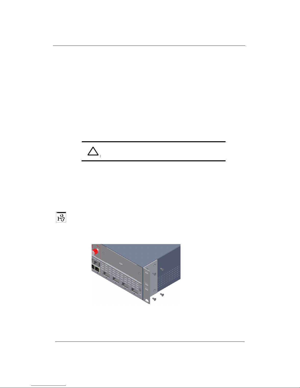
To rack mount the device, follow the below steps:
1. Attach the brackets flush with the front panel of the device using the screws
provided, as shown in the figure below.
Figure 3-1: Attaching brackets to AS9216
 Loading...