

Page 1
Installation and service of this product should be conducted by a trained
personnel to avoid bodily injury from electric shock or heavy object
Observe ESD (Electrostatic Discharge) practices during integration to avoid
possible damage to the board and / or other components
OSS212F-D5 Quick Guide
Version 1.10 – 2017.10.23
#
Description
Image / Description
Qty
1
OSS212F-D5
Enclosure
1
2
Motherboard
Tyan S7106GM2NR
1 3 CPU and memory
Intel Skylake and DDR4
Opt.
4
IO Cards
Opt.
5
Heatsink
2
6
2x 2.5” Drive Bay
Opt.
7
Slide Rail Kit + Screws
1 set
8
Power Cable*
2
9
Serial Cable*
1
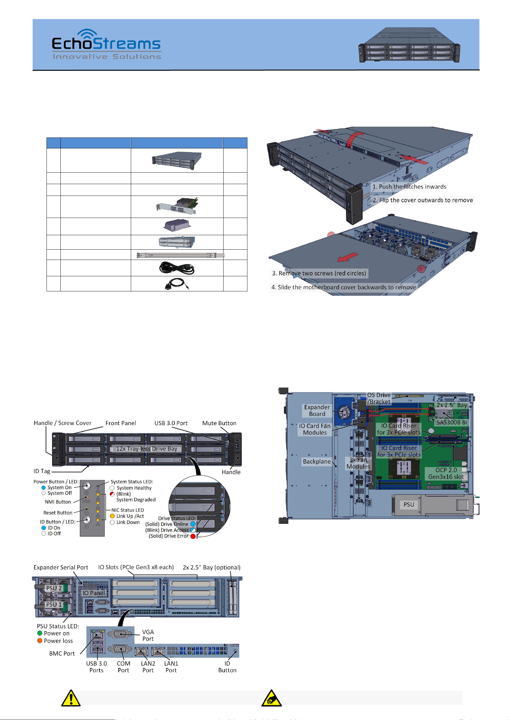
Thank you for your purchase of EchoStreams OSS212F-D5 Storage Server System!
1. Check the Content of the box. Please confirm that
your package contains the following:
3. Remove the Top Covers of the unit as follows:
* Inside the accessories box. Box may consist of screw sets for rail kit or
drives. If any items are missing, please contact your reseller or sales rep.
2. Get Familiar with the Unit.
OSS212F-D5 is a storage server supporting dual Intel
processor and front tray-less 12x 3.5” HDDs, an optional rear
2x 2.5” OS drive and 7x low profile PCIe slots in a 2U space.
Tyan S7106GM2NR and internal cabling are preinstalled.
Other motherboard model, IO cards, CPU, and memory can
be preinstalled upon request.
Front view of the unit
Remove the middle cover to get access to internal fans. The
rear cover is for motherboard access.
4. Inspect the Inside of the unit. Internal components
comprise of a Tyan motherboard, an expander board (to IO
cards), an optional rear 2x 2.5” bay, 3x system fan modules
and 2x IO card fan modules (all connected to the
motherboard).
Rear view of the unit
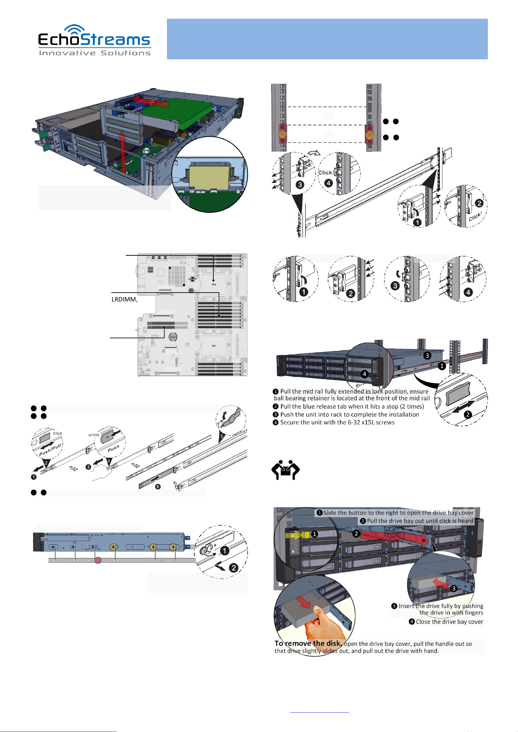
Install IO cards and OS disks as described below:
Page 2
OSS212F-D5 Quick Guide
For more information please visit our website at www.echostreams.com
Copyright © 2017, Echostreams Innovative Solutions LLC. All rights reserved.
1. Remove the riser card assembly from the enclosure
2. Open the mylar top cover
3. Insert PCIe card and secure with screw
To Install 2x 2.5" OS disks, use bracket. Note
the orientation. Secure the bracket from
outside the chassis
Support for Intel Xeon Skylake
Processor Family
Dual LGA3647
Max up to 205W TDP
Chipset PCH Intel C622
Support 8+8 DIMM slots
Up to 512GB RDIMM, 1TB LRDIMM,
2TB LRDIM 3DS
6 Channels per CPU
Populate from A0, B0, C0, D0, E0,
F0, B1, E1
Two PCIe Gen3 x24 slots
PCIE1 f/ CPU1, PCIE2 f/ CPU0
OCP2 is Gen3 x8, OCP1+2 is Gen3
x16, f/ CPU0
OCP4 is Gen3 x8, OCP3+4 is Gen3
x16, f/ CPU1
C0
B0
B1
A0
D0
E1
E0
F0
C0
B0
B1
A0
D0
E1
E0
F0
PCIE2
PCIE1
OCP 3
OCP 1
OCP 4
OCP 2
1 – 2 Pull the inner rails out. Pull the blue release tab when it hits a stop.
3 – 4 Keep extending inner rail and pull the white detach tab
when it hits the second stop
5 – 6 Unretract the mid rail by pulling the latch on the mid rail
1 2
3 4
5 6
Yellow circles are for standoff screws
Secure inner rail with
M4x4L screw (red)
To remove Inner rail from unit:
Pull the latch outward and remove
the keyhole from standoff
Red rectangles are locations for slide
rail position (front and rear posts)
Yellow circles are location for
enclosure screws (front only)
1U
2U
Rear Bracket
Front Bracket
1 – 2 Snap the rear part of slide rail
to rear posts
3 – 4 Snap the front part of slide rail
to front posts
1 2
3 4
Rear Bracket Front Bracket
8. Install the Outer Rails to the Rack as follows:
5. Install Motherboard Components. For details,
refer to the motherboard user’s guide.
To remove slide rails, use the latches to undo the assembly as follows:
9. Install the Unit to the Rack as follows:
6. Remove the Inner Rail from the slide rail.
7. Install Inner Rails to the enclosure.
For a complete instruction on how to install unit to the rack,
please follow the Slide Rail Installation Guide.
At least two people are recommended for
mounting process.
10. Install 2.5” Drives to the enclosure as illustrated:
Page 3
OSS212F-D5 Quick Guide
For more information please visit our website at www.echostreams.com
Copyright © 2017, Echostreams Innovative Solutions LLC. All rights reserved.
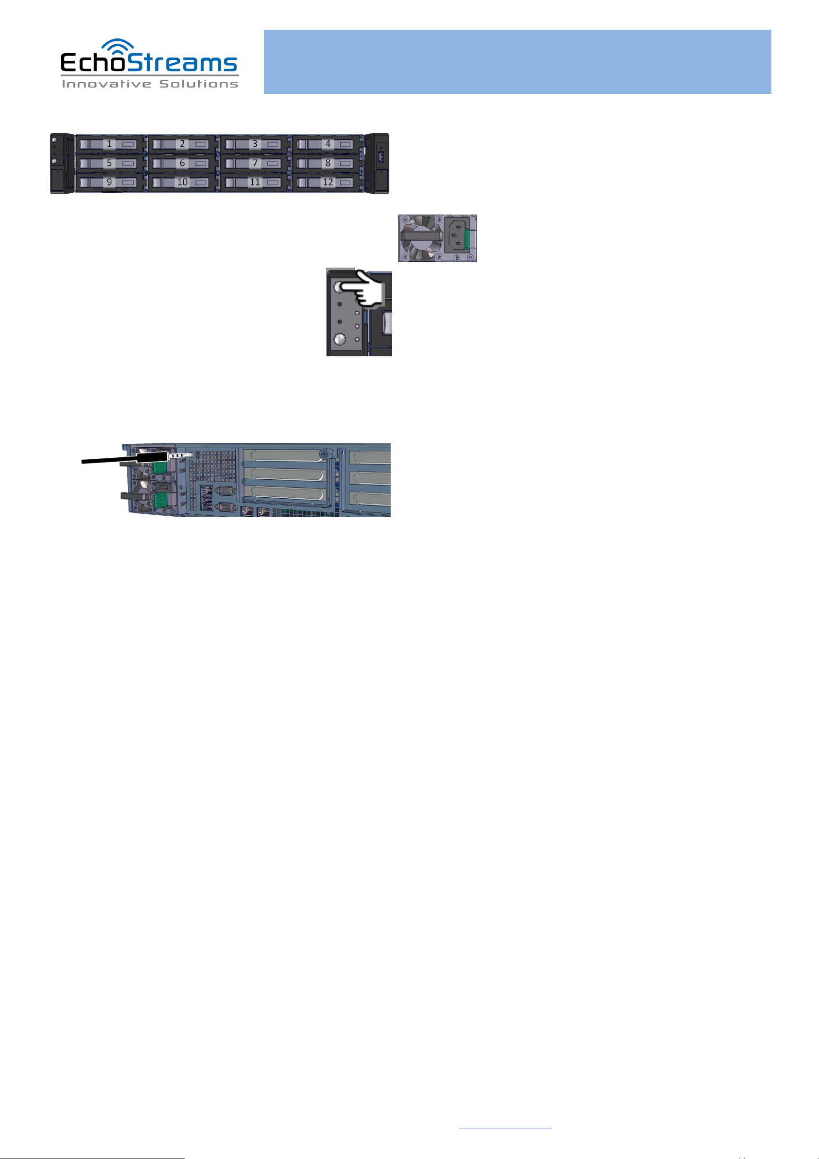
11. Drive Mapping of OSS212F-D5 is as follows:
12. Plug in the Power Cords to the AC receptacles
on the back of the unit.
13. Press the Power Button on the
front of the unit and for the system to boot up.
14. Access the Serial Console (when necessary) by
connecting a serial audio cable to the one of the console
ports. Use a terminal console with baud set 115200, 8, N, 1,
N. Type “help –a” for a list of commands.
For management through Eth port, refer to the User’s Guide.
 Loading...