

Page 1
FlacheSAN1L-D Enclosure Quick Guide
Version 1.00 Release 2014-08-05
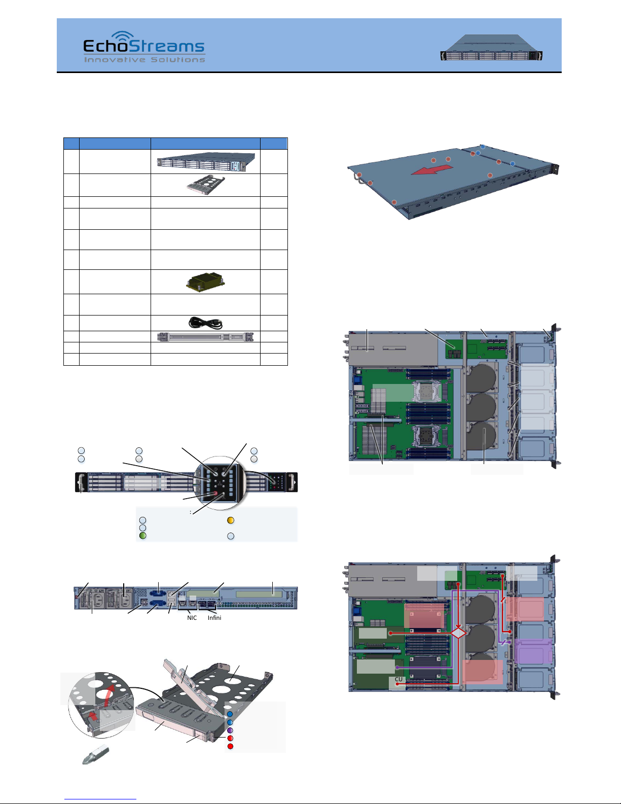
1. Check the content of the box. Please verify that your
package contains the following:
#
Description
Image / Description
Qty
1
1U 20-Bay
Enclosure
1
2
2.5” Tool-less Drive
Trays
20
3
Motherboard
Asrock EP2C602-2T/D16
1
4
Internal SAS cables
SFF8087-8087 or SFF8087-
8643 depending on SKU
5
5
Expander board or
OS disk bracket
Depending on SKU
1 6 CPU and memory
(optional)
Pre-installed upon request
2 sets
7
Heat sink
(optional)
2
8
Screw Sets*
for drives, motherboard, and
rail / rack
3 sets
9
Power Cable*
2
10
Rail Kit (optional)
1
11
This Quick Guide
1
12
Packaging box
1 set
* Inside the accessories box. If any items are missing, please contact
your authorized reseller or sales representative
2. Get familiar with the unit.
Front View
Power Button / LED:
System S tatus LED:
NIC LED:
(Sol id) System H ealthy
Syst em On
Syst em Off
Reset B utton
AC Pow er Of f
(Blink) Syst em Degraded
(Blink) Non-Critical
Alarm
(Sol id) Critical Alarm
ID B utto n / LED:
ID On
ID O ff
20 Dri ve Bays
Ear Handle
Link UP /Act
Link Down
1 2
Front Panel
Rear View
PCIe Gen3
x16 Slot
Pow er
Supply B
Pow er
Supply A
NIC
Por ts
USB
Por ts
USB
Por ts
Mgmt Port
(IPMI )
VGA
Por t
PCIe Gen3
x16 Port
Seri al
Por t
InfiniBand
Por ts
Alar m Mut e
Button
1 2
Drive Tray
3. Remove the top cover by removing the 8 screws on
the top of the unit and slide the cover towards the back of the
unit.
Remove additional 3 screws (blue circles) to open the middle
top cover (for backplane access).
4. Inspect the internal of the chassis. By default, it
consists of an Asrock EP2C602-2T/D16 motherboard, a set of
backplanes, blower modules, PCIe riser cards for IO cards, and
an option of an expander module or a drive bracket depending
on the order SKU.
OS HDD bracket location
5 columns
of
backp lanes
with on e
mini-SAS
connector
and 4 HDD
slots ea ch
PSU
Asroc k EP2C602-2T/D16
Moth erboa rd
PCIe Riser Slots Blowe r Modul e x3
Expan der Board Front Panel
See illustration below for the data path from disk devices to
the host. Two options are available: through an expander (red
path), and with no expander (purple path).
For expander mode, a set of SAS cables are routed from
backplanes to expander board and then a choice of routing to
an IO card or an on-board SCU port (SAS2/SATA3 6Gb/s).
IO Card
IO Card with
5 SAS ports
5 SAS UP
Ports
1 SAS DOWN
Port
5 SFF 8087-
8087 SAS
cables
1 SFF 8643 to
8643 or 8087
SAS c able
1 SFF 8643 -
8087 SAS
cable
SCU
Port
5 SFF 8087-
8643 SAS
cables
OR
For a non-expander SKU, in place of expander board, an OS
disk bracket occupies the space. Due to an absence of the
expander board, to access all 20 drives from the front bay, an
IO card with five SAS ports is required, e.g. Adaptec 72405.
Thank you for your purchase of FlacheSAN1L-D 1U 20-Bay Dual-Processor Storage Server!
2.5" 7mm
HDD / S SD
Tray
Driv e Lock
(unlocked position)
Tray Latch
Tray Handle
Drive Statu s LED:
(Sol id) Drive Onlin e
To unlock the drive l ock:
1. Push the
drive lock
latch
inwards
2. Then pull
it upwards
(Blink) Drive A ctivity
(Fast Blin k) Drive Loc ate
(Slow Blin k) Rebuild
(Sol id) Drive Fail
Tool-less drive tray is bes t used for SSDs.
It i s rec ommend ed t o appl y M3 screws when insta lling HDDs
Page 2
FlacheSAN1L-D 1U 20-Bay Storage Server Quick Guide
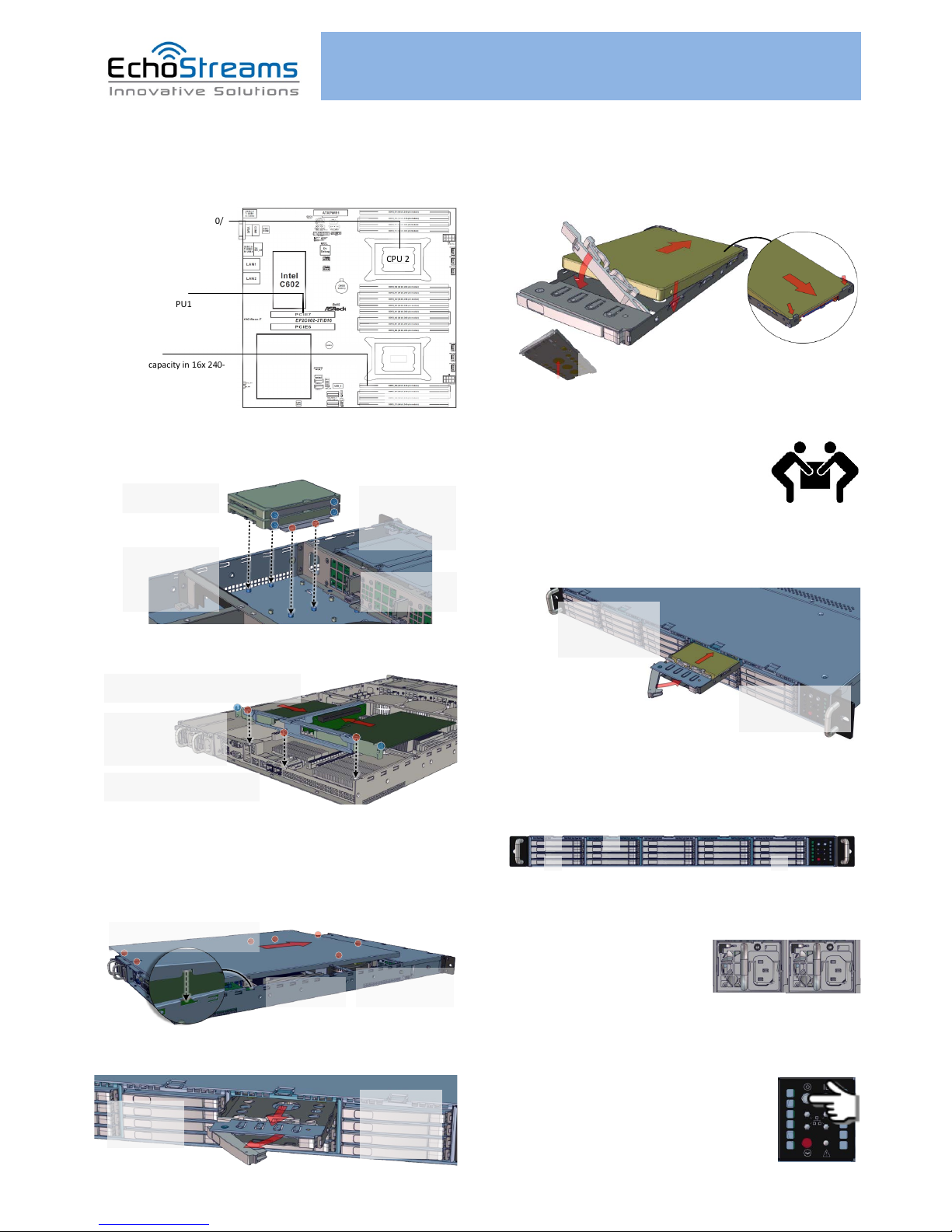
5. Install CPU and memory (may be sold separately)
to their respective slots on the motherboard. Please be aware
of each component’s installation requirements and
prerequisites. Refer to the motherboard’s TPS for details.
CPU 2
CPU 1
EP2C602-2T/D16
- Support for Intel Xeon E5-1600/
2600/4600 and V2 series
processors
- E5-1600 supports single socket
- Dual Socket R (LGA2011)
- DDR3 RDI MM
- 512 GB max capacity in 16x 240-
pin DIMM slots
- Quad Channel DDR3 1600/1333/
1066 LR/Registered/ECC/UDIMM
- PCIe Gen3 x16 sl ots
- PCIE6 is routed to CPU1
- PCIE7 is available only when
CPU2 is installed
6. Install OS disk(s) (may be sold separately) into the
bracket. Applies only to non-expander configuration.
1. Remove the bracket
from the enclosure
2. Install one or two
disk(s) to the bracket,
secure it with 4 M3
screws each at blue
circle locations
3. Place the OS dis k
brack et assembly back
to the enclosure.
Secure with provided
screws (re d circles)
4. Connect SATA
cables and po wer
cables to the disk(s)
7. Install IO cards (may be sold separately) to PCI-e slots.
1. Unscrew 3 screws (red circ les) to remove
the rise r card / IO c ard bracket
2. Slide IO c ard(s) to the
PCIe slot(s). Note their
brack et profile s. Secure at
blue circle(s)
3. Return the riser card assembly to
enclosure. Secure with screws
For more IO card information, refer to the user’s guide for the
IO card.
8. Put the top cover. Once we are finished with the
internals of the system, close the top of the chassis as
described below:
2. Slide the cover
forward
3. Secure the cover
with eight 6-32
thread s crews
1. Place the top cover to the
chassis using the pin as a guidance
9. Remove drive trays from the enclosure.
1. Push the tray
latch to release
the tray handle
2. Pull the t ray
handle to remove
the drive tray out
from the
enclosure bay
10. Install drives into trays. Follow the diagram
closely. SSD and HDD sold separately. For HDD installation, the
use of M3 screws is recommended.
1. Slide the drive in with the
IO connector side head first
to the ba ck of the tray
4. Snap in th e
hinge back to
lock positio n
3. Snug the
other end of
the driv e into
the tray
2. Make
sure that
the drive
goes
underneath
the hooks
To remo ve the disk, do the steps in reverse.
Poke fro m the bottom h ole to help rel ease the disk.
11. Place the unit to the rack. Please refer to Rail Kit
Installation Guide on how to mount the
enclosure.
Caution: At least two people are required to
lift a fully populated chassis
12. Install the populated drive trays into the
enclosure with the drives properly secured to the hard drive
trays.
1. Push the tray by the
latch all the way into the
drive bay to ensure a
complete insertion
2. Secure the drive tray to
the enclosure by placing the
tray h andle to lock positi on
13. Drive mapping incrementally goes from left to
bottom going and to the right, depending on the cable
connection of the expander / on-board SATA ports.
1
204
5
14. Plug in the power cords to the AC receptacles on
the back of the unit and secure it with the wire lock.
15. Press the power button on the front of the unit
after connecting a monitor and input devices, and get ready for
software setup.
If you have any technical questions, please contact your authorized dealer before contacting us.
For more information please visit our website at www.echostreams.com
 Loading...