

Page 1
eDrawer 4048 Hardware Quick Guide
Version 2.40 Release 2014-03-24
1. Push the
drive tray to
its slo t
2. Close the
tray handle
3. Secure the
tray lock
1. Check the content of the box. Please confirm that
your package contains the following:
#
Description
Image / Description
Qty
1
eDrawer 4048
Enclosure
1
2
3.5” Drive Trays
48
3
Screw Set for
Mounting Drives*
1 set
4
Power Cable*
2
5
Serial Cable*
1
6
Rail Kit
1 set
7
Cable Mgmt Arm
Kit
1 set
8
Chassis Lift
Handles*
2 9 SFF 8644-8644 /
SFF 8088-8644
optional
2
10
This Quick Guide
1
11
Packaging
1 set
* Inside the accessories box. If any items are missing, please contact your
authorized reseller or sales representative
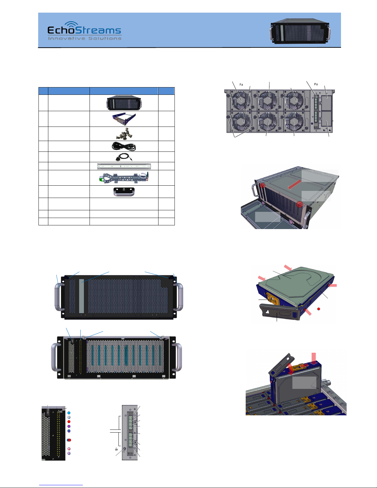
2. Get familiar with the unit.
Front view of the unit (front door closed and opened)
Ear Handle
Thumb screw fo r
front door
Thumb screw fo r
front door
HDD St atus
LED Window
Ear Handle
Thumb screw
for top cover
Power Switch
HDD St atus
LED Panel
Thumb screw
for top cover
Front and Back Panel
2
1
4
3
6
5
8
7
10
9
12
11
14
13
16
15
17
19
18
21
20
23
22
24
26
25
28
27
30
29
32
31
34
33
36
35
38
37
40
39
41
43
42
45
44
47
46
48
Power Sw itch
HDD Status LED:
EXP
GRP-1
Host
Exp
1
2
1
2
Host
Exp
1
2
1
2
EXP
GRP-2
Debug
Console
Primary Host Port
for HD D 1-24
Expander-A
for HD D 1-24
Expander-B
for HD D 25-48
Secondary Host Port
Seria l Port
Primary Expansion Port
Secondary Expansion Port
Primary Host Port
for HD D 25-48
Secondary Host Port
Primary Expansion Port
Secondary Expansion Port
(Solid) Drive Online
(Solid) Drive Off
(Alternatin g Blink)
Drive Fault /RAID Fail
(Solid) RAID Drive
(Blink Purple on Blue)
RAID Activity/Rebuild
(Blink) Driv e Missing
(Blink) Driv e Locate
(Blink) Dri ve Spin/Act
Rear view of the unit
SAS Expander Module
Fan Module 2
Power Supply A
Power Supply B
Thumb screws for
Fan Module
Fan Module 3
Fan Module 5
Fan Module 4 Fan Module 6
Fan Module 1
3. Open the Top Cover of the unit as indicated.
1. Open the
front door
2. Loosen the
thumbscrews
3. Slide the top cover to
the front, then lift up
4. Install HDDs to Drive Trays with hard drive (6-32
thread) screws at the locations as indicated by the red arrows.
SAS and SATA drives may be sold separately.
3.5" SAS/SATA
Drive
Tray Handle
Tray Lock
HDD LED St atus
Light Pipe:
Drive Fail
5. Install the Drive Trays to the enclosure as illustrated
by the picture.
Caution: HDD tray orientations are opposite for every other
rows. Be cautious when installing the drive trays.
While holding the tray handle, it is recommended to push the
drive tray at the location indicated by the arrow for a complete
insertion.
This step may also be done after placing the unit to the rack.
Congratulation on your purchase of EchoStreams eDrawer 4048 System!
Page 2
eDrawer 4048 Hardware Quick Guide
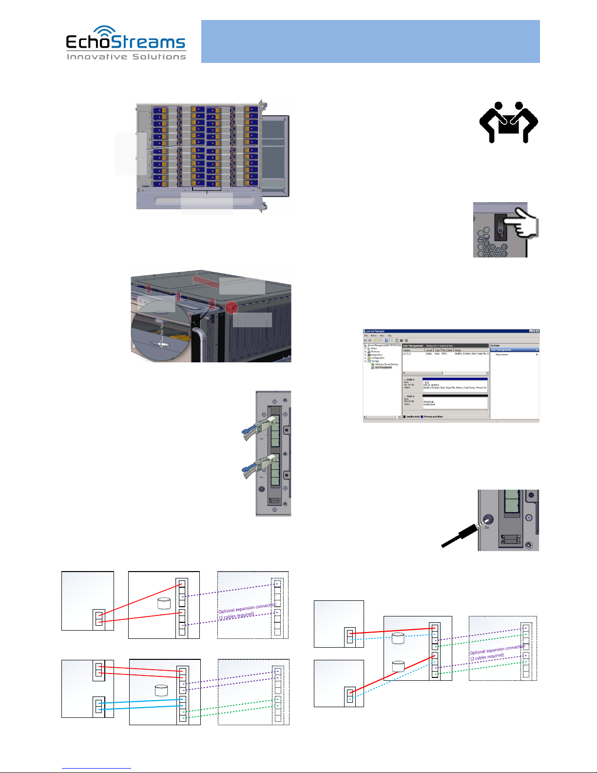
6. Drive Mapping of the system is as follows:
1
2
3
4
5
6
7
8
9
10
11
12
13
14
15
16
17
18
19
20
21
22
23
24
25
26
27
28
29
30
31
32
33
34
35
36
37
38
39
40
41
42
43
44
45
46
47
48
HDD 1~12
HDD 13~24
HDD 25~36
HDD 37~48
Look for any
Red LED
from the
trays to
locate fail ed
drives
Note the orientation
of the drive tra ys
chang es every r ow
7. Close the Top Cover and the front door. Please
position the top cover at the described location before sliding
it close.
1. Align gui de
pin to the hole
2. Slide the cover
backwards
3. Secure the
thumbscrews
Caution:
Slide top cover on lightly so HDDs won’t be shocked
8. Connect mini-SAS HD cable (SFF-8644)
to the desired mini-SAS HD ports.
For a host to be able to see all 48 drives, a
minimum of two mini-SAS HD cables is
required. Connect those two cables to
Expander-A’s Primary Host Port and to ExpanderB’s Primary Host Port (see picture).
Connect the cables on the host side
accordingly.
See the next step for optional connections using
the other mini-SAS HD ports.
9. Review your hardware setup. It should be a
variation of the diagrams below:
10. Place the unit to the rack. Please refer to Rail Kit
Installation Guide on how to mount the
enclosure.
Caution: At least two people are required to
lift a fully populated chassis
11. Plug in the Power Cords to the AC receptacles on
the back of the unit.
12. Press the Power Switch on
the front of the unit and wait about 30
seconds until the unit is ready.
Once it’s ready, power up your host unit.
13. Access the disks on the Host. This example
assumes Windows OS is used for the host. Go to “Disk
Management” to see the disks. If the host is using SAS RAID
adapter, use the RAID Management Software to manage the
disks.
14. Access the Serial Console (when necessary) by
connecting a serial audio cable to the debug console port and
use a terminal console with baud rate 38400, 8, N, 1, N.
Once there, type “help –a” for the list of commands.
EXP
GRP-1
Host
Exp
1
2
1
2
Host
Exp
1
2
1
2
EXP
GRP-2
Debug
Console
Exp
1
2
Debug
Console
Your eDrawer 4048 Enclosure
Hos t
eDraw er 4048 Expansion
Unit (optiona l)
Required
Required
SAS card
Optio n 1: Default configuration with optional expansion
x48
Your eDrawer 4048 Enclosure
Hos t
eDraw er 4048 Expansion
Unit (optional )
SAS card
Sec ond
SAS card
Optio n 2: Optimized Bandwidth configuration with optional expansion
x48
Your eDrawer 4048 Enclosure
Hos t
Second Host
eDraw er 4048 Expansion
Unit (optional )
SAS card
Second cables are required when
Secondary connection to the host is
present
Optio n 3: Shared s torage con figuration (24 drives for each host)
with optional Optimized Bandwidth configuration and expansion
x24
x24
Optional for
bandwidth increase
SAS card
Pri
Sec
Pri
Sec
Pri
Sec
Pri
Sec
If you have any technical questions, please contact your authorized dealer before contacting us.
For more information please visit our website at www.echostreams.com
 Loading...