

Page 1
DSS212J Enclosure Quick Guide
Version 1.00 – 2014.08.29
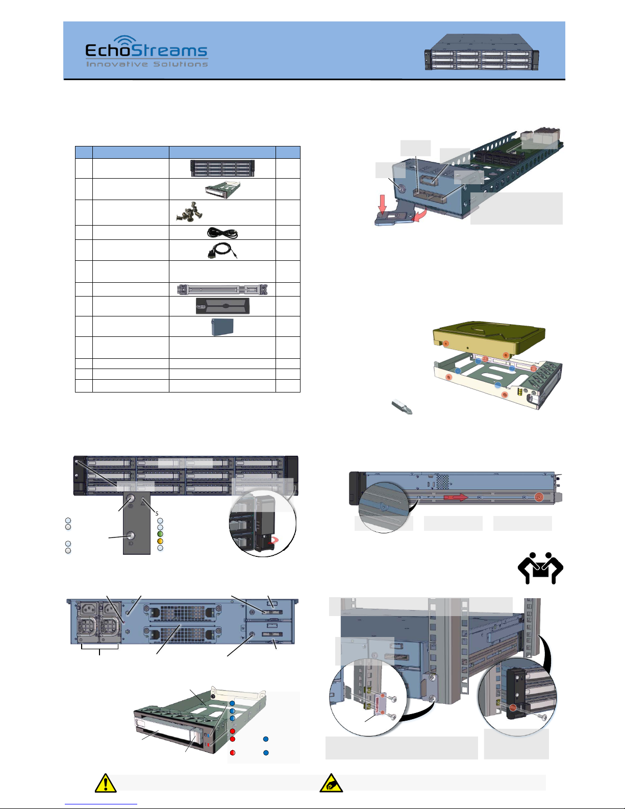
1. Check the content of the box. Please confirm that
your package contains the following:
#
Description
Image / Description
Qty
1
2U 12-Bay JBOD
Enclosure
1
2
3.5” Drive Trays
12
3
6-32 PH#1 Screw
Set*
for mounting drives
1 set
4
Power Cable*
2
5
Serial Cable*
1
6
Fix mount rail kit
Includes rail, ear bracket, and
screw set*
1 set
7
Slide Rail Kit (opt.)
1 set
8
Bezel (optional)
1
9
Expander dummy
cover*
1
10
External mini-SAS
cables (optional)
SFF8088-8088 or SFF80878644 depending on host card
1 set
11
Anti-static bags*
For drive or drive tray
12
12
This Quick Guide
1
13
Packaging
1 set
* Inside the accessories box. If any items are missing, please contact your
authorized reseller or sales representative
2. Get familiar with the unit.
Front view of the unit
Front Panel
12x 3.5" Dri ve Bays
Power Butto n / LED:
System S tatus LED:
(Sol id) System H ealthy
Syst em On
Syst em Off
ID B utto n / LED:
ID On
ID O ff
AC P ower Off
(Blink) Syst em Degraded
(Blink) Non-Critical Alarm
(Sol id) Critical Alarm
Turn the ear handle
inwards to open and
reveal the rackmount
scr ew ho le
Rear view of the unit
Power Supply
Blower Modules
Sec ondar y
Expander Module
Primary Expander
Mod ule
Seri al Port
SAS Ports
PSU Alar m
Mute Button
Ground
Connector
3.5” Drive Tray
Expander Module
Expansion
Por t
Hos t Por t
Expander
Board
Fail-Over
Por t*
To remove the Expander Module:
1. Press the latch downwards
2. Pull the handle outward and
pull the module out
Seri al Port
** The Fail-Over port is used for a system configuration with
LSI Syncro CS redundant RAID controller cards (CS 9286-8e) in
the host system.
4. Install drives into trays. Follow the diagram closely.
SAS drives are recommended to fully utilize the dual expander
DSS212J. HDD sold separately.
To insta ll 2.5" drive s in 3.5"
drive tray, apply four M3
screws from the bottom of the
tray to the underside of the
drive (b lue circles)
Appl y four 6-32 sc rews
from the sides of the
tray to the side of the
drive (re d circles)
Use the screw bit PH#1 for t he
provide d screws
5. Install the Fix Mount Rail. Follow the instruction
below. A number of rail length is available for different rack
depths.
1. Align the fi x rails
to the hooks
2. Slide the r ails
backwards
3. Secure the rails
with M4 screws
6. Place the unit to the rack. Follow the
diagram below. Caution: At least two people are
required to lift a fully populated chassis.
1. Place the square nuts to the front and back rack poles. Note the squar e
nut locati ons with respect to the chassis U hei ght from the illus trations
Adjustment
brack et
4. Secure th e enclosure
by applying M5 screw
through the ears of the
chassi s
2. Install ad justment
brackets and secure
them with M5 screws
3. Carefully mou nt the chassis to th e rack by aligni ng the ti p
of the fix mount rail to the opening of the adj ustment bracket
Thank you for your purchase of DSS212J Dual-Expander JBOD unit!
3.5"/2.5"
HDD/S SD Tray
Tray Latch
(press this to release the handle)
Tray Handle
Drive Statu s LED:
(Sol id) Drive Onlin e/Idle
(Blink) Drive Ac tivity
RAID/Drive Fa ult
(Solid with Act/Idle)
(Slow Blink) Driv e Locate
(Sol id) Drive Off / Missing
RAID Rebuild
(Blink with Act/Idle)
Installation and service of this product should be conducted by a trained
personnel to avoid any bodily injury from electric shock or heavy object hazard
Observe ESD (Electr ostati c Di scharg e) practices during integration to avoid
possi ble damage to t he boar d and / or other components
Page 2
DSS212J Enclosure Quick Guide
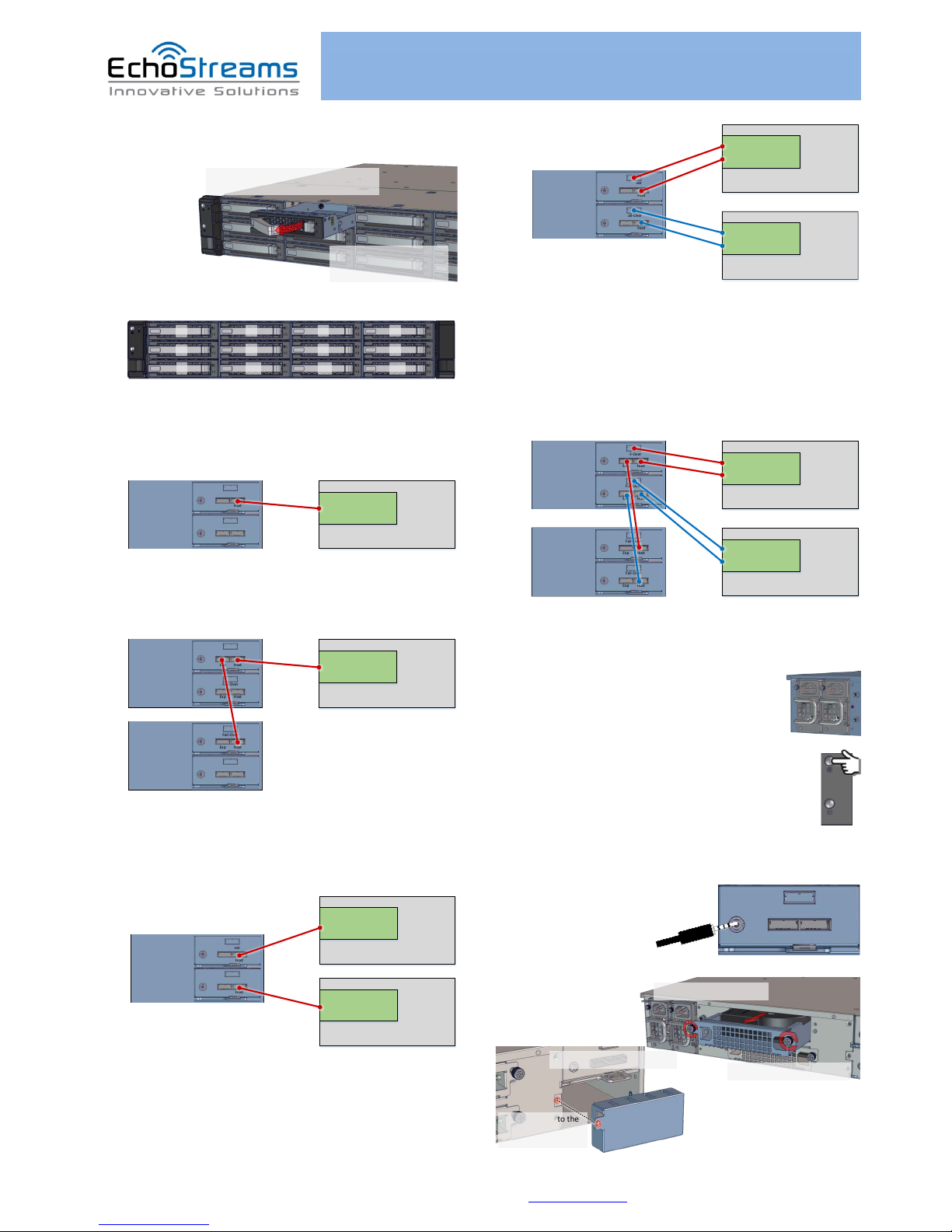
7. Install the populated drive trays into the
enclosure with the drives properly secured.
2. Secure the drive tray to the
enclosure by placing the tray
handl e to loc k positi on
1. Push the tray by the latch al l the way in to
the drive bay to ensure a complete insertion
8. Drive Mapping of DSS212J is as follows:
1
5
9
2
6
10
3
7
11
4
8
12
9. Plug in the mini-SAS cables to the SAS ports at the
back of the unit. Refer to the system configurations below to
decide on which port to use.
DSS212J
Primar y
Secondary
Fail-Over
Fail-Over
Exp H ost
Exp H ost
Host / Client
SAS Adapter
Single expander mode: SAS drives are not required, no high
availability is possible with this configuration. The SAS
HBA/RAID controller will see all 12 HDDs from DSS212J.
Connect SAS cable to Host Port of the Primary Module.
DSS212J
Primar y
Secondary
Fail-Over
Fail-Over
Exp H ost
Exp H ost
DSS212J
Primar y
Secondary
Fail-Over
Fail-Over
Exp H ost
Exp H ost
Host / Client
SAS Adapter
Daisy-chain mode: a single expander mode with expandable
storage. The SAS HBA/RAID controller will see the collective
HDDs from the daisy-chained DSS212Js.
Connect the Expander Port from the first unit to the Host Port
of the second unit and so on.
DSS212J
Primar y
Secondary
Fail-Over
Fail-Over
Exp H ost
Exp H ost
Host / Client
SAS Adapter
Host / Client
SAS Adapter
Dual expander mode: SAS drives are required. Two hosts are
able to connect to the unit storage through the dual port of the
SAS drives. No shared storage. No high availability. Each host
accesses a different set of drives.
Connect SAS cables to the Host Port of each expander.
DSS212J
Primar y
Secondary
Fail-Over
Fail-Over
Exp H ost
Exp H ost
Host / Client
LSI Syncro
Host / Client
LSI Syncro
Syncro mode: SAS drives are required. Two servers with LSI
Syncro CS redundant RAID controller (CS 9286-8e) are required
for this configuration. The storage is shared between two
servers providing high availability.
Communication between two Syncro CS redundant RAID
controller cards is achieved through the Fail-Over ports.
Connect SAS cables to the Host Port and Fail-Over port of each
expander.
DSS212J
Primar y
Secondary
Fail-Over
Fail-Over
Exp H ost
Exp H ost
Host / Client
LSI Syncro
DSS212J
Primar y
Secondary
Fail-Over
Fail-Over
Exp H ost
Exp H ost
Host / Client
LSI Syncro
Syncro mode daisy-chained: A Syncro mode with expanded
storage. Connect the Expander Port from the first unit to the
Host Port of the second unit and so on.
10. Plug in the power cords to the AC
receptacles on the back of the unit and secure it
with the wire lock.
11. Press the power button on the front of
the unit after connecting a monitor and input devices,
and get ready for software installation.
Access the Serial Console (when necessary) by
connecting a serial audio cable to the debug console port and
use a terminal console with baud
rate 38400, 8, N, 1, N.
Once there, type “help –a”
for the list of commands.
To remove Blower
Module
follow the
diagram on the right
The following illustration
explains how to install an
Expander Cover
Fail-Ov er
Exp Host
1. Loose n the thumbscr ews
2. Pull out the blower module
1. Remove the expander module
2. Align cover to the
expander slot and
secure with screw
For software guide, please refer to the respective adapter’s Software Guide
For more information please visit our website at www.echostreams.com
Copyright © 2014, Echostreams Innovative Solutions LLC. All rights reserved.
 Loading...