

Page 1
Satellite Television
KVHTracVision
®
4
user’s guide
•
Operating Instructions
A Guide to TracVision 4
Page 2
Welcome to TracVision 4
TracVision 4
User’s Guide
Congratulations on your choice of the TracVision 4, one of the
most advanced automatic satellite tracking systems available
today. This user’s guide provides all of the basic information
required to use this system and receive the satellite entertainment
you want. Detailed installation, configuration, and maintenance
information is provided in the TracVision 4 Technical Manual.
Throughout this manual, important information is marked for
your attention by these icons:
Direct questions, comments, or suggestions to:
KVH Industries, Inc. KVH Europe A/S
50 Enterprise Center Kokkedal Industripark 2B
Middletown, RI 02842-5279 USA 2980 Kokkedal, Denmark
Tel: +1 401 847-3327 Tel: +45 45 160 180
Fax: +1 401 849-0045 Fax: +45 45 160 181
E-mail: [email protected] E-mail: [email protected]
Internet: www.kvh.com Internet: www.kvh.com
If you have any comments regarding this manual, please e-mail
them to [email protected]. Your input is greatly appreciated!
KVH Part # 54-0150-01 Rev. B
© 2004, KVH Industries, Inc. All rights reserved.
TracVision 4 Serial Number
This serial number will be required
for all troubleshooting or service
calls made regarding this product.
Click here to go to our stateof-the-art Customer Support
web page...the fastest and
easiest way to get all of your
questions answered!
A helpful tip that either directs you to
a related area within the manual or
offers suggestions on getting the
highest quality out of your system.
An alert to important information
regarding procedures, product
specifications, or product use.
Information about installation,
maintenance, troubleshooting, or
other mechanical issues.
An electrical safety warning to help
identify electrical issues that can be a
hazard to either this KVH product or
a user.
Page 3

TracVision®and KVH®are registered trademarks
of KVH Industries, Inc.
TracNet
™
is a trademark of KVH Industries, Inc.
DVB
®
(Digital Video Broadcasting) is a registered trademark of the DVB Project.
DIRECTV
®
is a registered trademark of DIRECTV, Inc.,
a unit of the DIRECTV Group.
DISH Network
™
is an official trademark of
EchoStar Communications Corporation.
ExpressVu is a property of Bell ExpressVu, a wholly owned
subsidiary of Bell Satellite Services.
Page 4

54-0150-01
i
Table of Contents
Table of Contents
1 Introduction . . . . . . . . . . . . . . . . . . . . . . . . . . . . . . . . . .1
1.1 TracVision 4 System Overview . . . . . . . . . . . . . . . . . . . . . . . . .3
1.2 TracVision 4 Components . . . . . . . . . . . . . . . . . . . . . . . . . . . . .5
2 Using Your TracVision 4 . . . . . . . . . . . . . . . . . . . . . . . . . .7
2.1 Receiving Satellite Signals . . . . . . . . . . . . . . . . . . . . . . . . . . . .9
2.2 Turning On the System . . . . . . . . . . . . . . . . . . . . . . . . . . . . . .10
2.3 Changing Channels and Switching
to the Second Satellite . . . . . . . . . . . . . . . . . . . . . . . . . . . . . .11
2.4 Watching Television . . . . . . . . . . . . . . . . . . . . . . . . . . . . . . . .14
2.5 Internet Access . . . . . . . . . . . . . . . . . . . . . . . . . . . . . . . . . . . .15
3 Troubleshooting . . . . . . . . . . . . . . . . . . . . . . . . . . . . . . .17
3.1 Troubleshooting Matrix . . . . . . . . . . . . . . . . . . . . . . . . . . . . . .19
3.2 Causes and Remedies for Common
Operational Issues . . . . . . . . . . . . . . . . . . . . . . . . . . . . . . . . .20
3.3 IRD Troubleshooting . . . . . . . . . . . . . . . . . . . . . . . . . . . . . . . .23
3.4 Antenna Gyro and LNB Faults . . . . . . . . . . . . . . . . . . . . . . . .23
Page 5

Introduction
54-0150-01
1
1 – Introduction
This section provides a basic overview of the TracVision 4 system. It
explains how the system works and describes the function of each
component.
Contents
1.1 TracVision 4 System Overview . . . . . . . . . . . . . . . . . . . . . . . . . . . . . . .3
1.2 TracVision 4 Components . . . . . . . . . . . . . . . . . . . . . . . . . . . . . . . . . . .5
Page 6
Introduction
54-0150-01
3
1.1 TracVision 4 System Overview
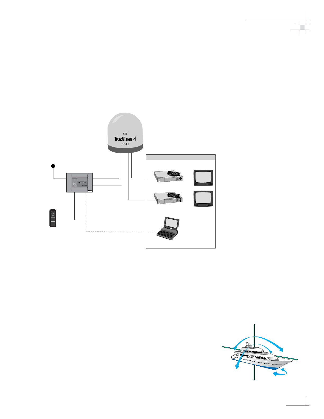
A complete satellite TV system, illustrated in Figure 1-1, includes
the TracVision 4 antenna connected to the switchplate, an IRD
(satellite TV receiver), and a television set. The optional TV/SAT
Switch allows you to select a satellite at the press of a button. A
desktop or laptop computer is used to configure the system and
conduct diagnostics.
System Compatibility
The TracVision 4 satellite antenna is fully compatible with Digital
Video Broadcasting (DVB
®
) satellites, as well as DIRECTV®‘s
Digital Satellite Service (DSS) satellites. The system is also fully
compatible with KVH’s TracNet
™
2.0 Mobile High-speed Internet
System (for more information about TracNet 2.0, please visit our
web site at www.kvh.com).
In-motion Tracking
The TracVision 4 uses a state-of-the-art actively stabilized antenna
system. Once the satellite is acquired, the antenna gyro
continuously measures the heading, pitch, and roll of your vessel
and sends commands to the antenna motors to keep the antenna
pointed at the satellite at all times.
Figure 1-1
TracVision 4 System Diagram
Figure 1-2
TracVision Identifies and
Compensates for Vessel Motion
11-16 VDC
3.5 - 4.5 Amps
TV/SAT Switch
(optional)
r
o
r
r
E
t
A
a
S
t
B
a
S
e
l
S
e
c
t
C
h
i
n
g
a
n
S
g
a
t
e
s
:
e
l
lit
.
1
P
S
u
e
t
h
s
c
u
e
t
n
l
o
t
b
2
.
a
i
t
while
S
W
a
t
A
r
o
r
k
s
g
lin
e
e
n
B
b
3
.
y
w
h
R
e
a
d
S
e
n
A
a
t
r
o
S
a
t
B
s
t
y
s
a
s
o
l
r
g
i
d
e
e
n
O
e
r
i
c
a
t
h
d
t
In
r
s
:
o
•B
g
k
i
n
h
lin
t
o
b
i
t
in
r
i
a
g
liz
g
:
i
n
e
e
n
•E
r
r
o
h
r
li
g
t
r
g
b
:
k
i
n
e
d
lin
l
e
m
e
m
b
s
y
s
t
o
r
p
Switchplate
TracVision 4 Antenna
Powe r
Data
PC Maintenance
Satellite Receiver 1
RF
RF
Satellite Receiver 2
Options Purchased Separately
TV 1
TV 2
Laptop PC
TracVision
Page 7

54-0150-01
4
TracVision 4 User’s Guide
Satellite Library
Your TracVision 4 includes a pre-programmed satellite library of
North American and European satellite services. If the satellite
service you wish to receive is not already in the satellite library,
an authorized technician can add two additional satellites of your
choice to the library.
Tables 1-1 and 1-2 list the possible satellite pairs that may be
selected in North America and Europe. Contact the satellite TV
service provider of your choice for complete details and a map of
the service’s coverage area.
TracVision 4’s default satellite pairs
are:
N. America (US DIRECTV):
DSS_101 & DSS_119
Europe: Astra 1 & Hotbird
Table 1-2
Available Satellite Pairs - Europe
(European LNB required)
Table 1-1
Available Satellite Pairs
- North America
(North American LNB required)
DSS_101 DSS_119 Echo_61 Echo_110 Echo_119 Echo_148 Expressvu ExpressTV
DSS_101 ✓✓✓
DSS_119 ✓✓✓
Echo_61 ✓✓ ✓✓
Echo_110 ✓ ✓✓✓✓
Echo_119 ✓✓ ✓✓✓
Echo_148 ✓✓ ✓✓
Expressvu ✓✓✓✓✓✓ ✓
ExpressTV ✓✓✓✓✓✓✓
Astra 1 Astra 2N Astra 2S Hispasat Hotbird Sirius Thor
Astra 1 ✓✓ ✓✓
Astra 2N ✓✓
Astra 2S ✓✓
Hispasat
Hotbird ✓✓ ✓ ✓
Sirius ✓✓✓
Thor ✓
Page 8
Introduction
54-0150-01
5
1.2 TracVision 4 Components
Your TracVision 4 system includes the following components:
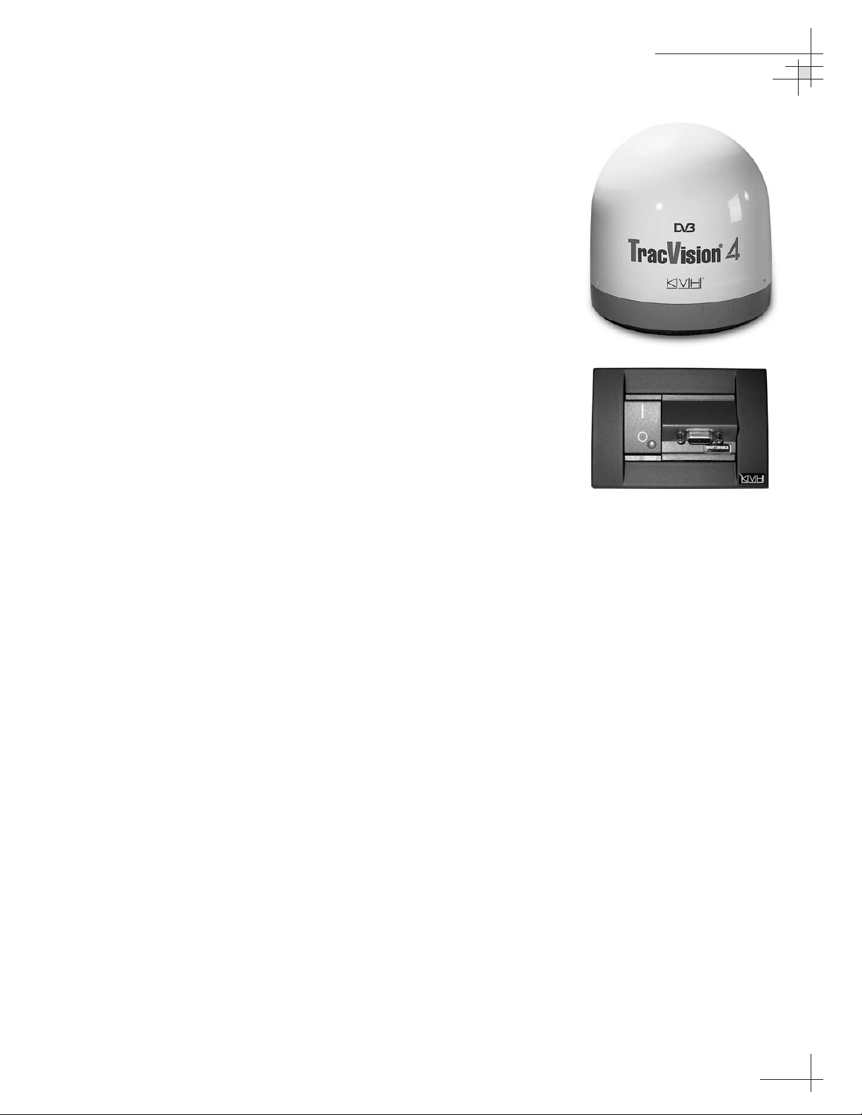
Antenna Unit
The antenna unit houses the antenna positioning mechanism, low
noise block (LNB), power supply, and control elements within a
molded ABS radome. Weathertight connectors on the bottom of
the baseplate join the power, signal, and control cabling from
belowdecks units.
Switchplate
The switchplate controls power to the antenna via the On/Off
switch. It also provides a DB9 maintenance port for connecting a
computer or TV/SAT Switch for changing satellites and
configuring the system.
Integrated Receiver Decoder (IRD)
(Satellite TV Receiver)
The IRD (purchased separately) receives satellite signals from the
antenna unit for signal processing and channel selection, and
sends the signals to the TV set for viewing. Please refer to the
user’s manual provided with your selected IRD for complete
operating instructions.
Page 9

Using Your TracVision 4
54-0150-01
7
2 – Using Your
TracVision 4
This section explains everything you need to know to operate your
TracVision 4 system. Antenna unit initialization and satellite acquisition
are automatic, making the system very easy to use.
Contents
2.1 Receiving Satellite Signals . . . . . . . . . . . . . . . . . . . . . . . . . . . . . . . . . .9
2.2 Turning On the System . . . . . . . . . . . . . . . . . . . . . . . . . . . . . . . . . . . .10
2.3 Changing Channels and Switching to the Second Satellite . . . . . . . . .11
2.4 Watching Television . . . . . . . . . . . . . . . . . . . . . . . . . . . . . . . . . . . . . .14
2.5 Internet Access . . . . . . . . . . . . . . . . . . . . . . . . . . . . . . . . . . . . . . . . . .15
Page 10
Using Your TracVision 4
54-0150-01
9
2.1 Receiving Satellite Signals
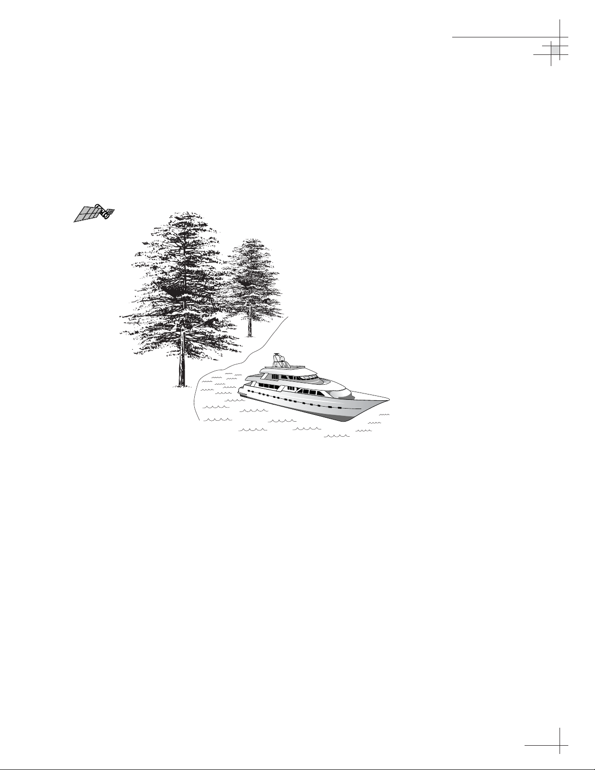
For TracVision 4 to receive satellite TV signals, the antenna must
have a clear line of sight to the satellite. If you only receive
intermittent signals or the antenna cannot find the satellite, check
around your vessel for any objects that could be blocking the
signal, such as other vessels, trees, buildings, other onboard
equipment, etc.
You must also be located within the selected satellite’s coverage
area in order to receive its signal. Refer to your satellite television
service manual to check the viable coverage area. For your
convenience, KVH provides links to several web sites that offer satellite
coverage information. Simply go to our web site at: www.kvh.com/
footprint.
Figure 2-1
Be Aware of Objects that Might
Block the Satellite Signals
TracVision
Page 11
54-0150-01
10
TracVision 4 User’s Guide
2.2 Turning On the System
The TracVision 4 system is easy to use. Antenna unit initialization
and satellite acquisition are completely automatic.
To use the TracVision 4 system, follow the steps below.
1. Turn on the IRD and the television. (Refer to your
IRD user’s manual for complete operating
instructions for the IRD.)
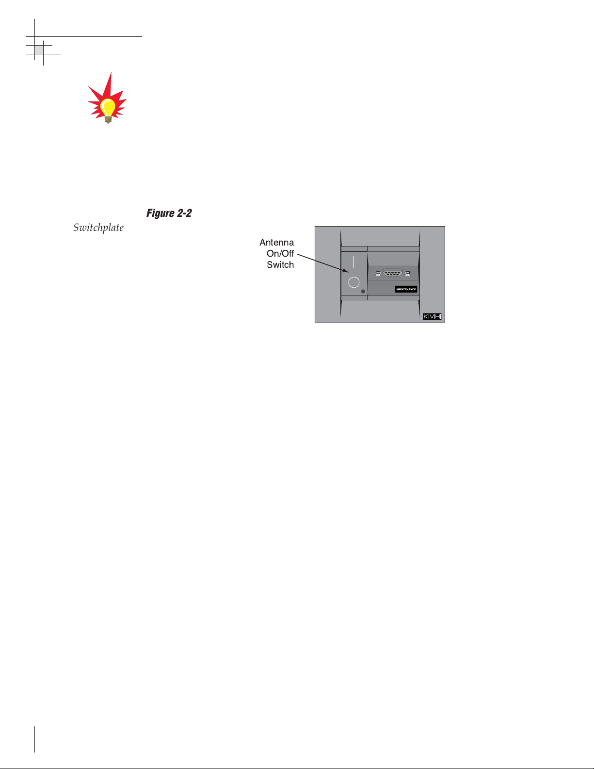
2. Turn on the antenna using the switchplate’s On/Off
switch.
3. Avoid turning the vessel for 60 seconds after turning
on the antenna to allow the antenna gyro to initialize
properly.
To minimize the time it takes the
antenna to acquire the satellite, do
not change the channel during the
startup process or cable unwrap.
Figure 2-2
Switchplate On/Off Switch
Page 12
Using Your TracVision 4
54-0150-01
11
2.3 Changing Channels and
Switching to the Second Satellite
If you have followed the installation instructions, your system
should be set to the active satellite pair of your choice and the
system should have downloaded the appropriate channel guides.
You must also have a properly configured IRD (if this has not
been done, refer to your IRD User’s Manual for instructions for
your specific IRD).
Your TracVision system is programmed to track either of two
satellites, stored in memory as Satellite A and Satellite B. You can
use the IRD remote control, the optional TV/SAT Switch, or a PC
to select between the two satellites.
Using the IRD Remote Control to Switch Between
Satellites
When the TracVision 4 system and the IRD have matching
configurations, switching from one satellite to the other is as easy
as changing the channel using the remote control. TracVision 4
will automatically switch from Satellite A to B and back again as
necessary to receive your selected channel.
DIRECTV Satellite Subscribers
DIRECTV subscribers in certain regions of the United States will
require a DSS Plus IRD to receive broadcasts from multiple
satellites.
If connected to the antenna’s RF1 connector, the DSS Plus IRD
allows you to switch channels using the IRD remote control. If
you are a DIRECTV subscriber, but do not have a DSS Plus IRD,
or you are using a multiswitch, use the optional TV/SAT Switch*
or a PC, as described in the following sections.
EchoStar and ExpressVu Satellite Subscribers
EchoStar and ExpressVu subscribers will need to use the optional
TV/SAT Switch* or a PC to change satellites, as described in the
following sections.
* To order a TV/SAT Switch (KVH Part Number 01-0245), please call +1 401 847-3327.
The satellite configuration on
your IRD must match the satellite
setting on the TracVision 4
system.
Satellite A on the TracVision 4 must
be the same satellite as IRD
Alternative 1 (or A, based on your
IRD) and must be assigned the IRD
DiSEqC 1 setting.*
Satellite B on the TracVision 4 must
be the same satellite as IRD
Alternative 2 (or B, based on your
IRD) and must be assigned the IRD
DiSEqC 2 setting.*
Refer to your IRD user manual for
complete instructions for your IRD.
*DiSEqC settings only apply to
European systems and DIRECTV
DSS Plus
™
IRDs.
When you switch from one satellite
to another, all IRDs connected to
the system will receive signals from
the newly selected satellite.
Page 13
Using the TV/SAT Switch to Switch Between Satellites
- Optional
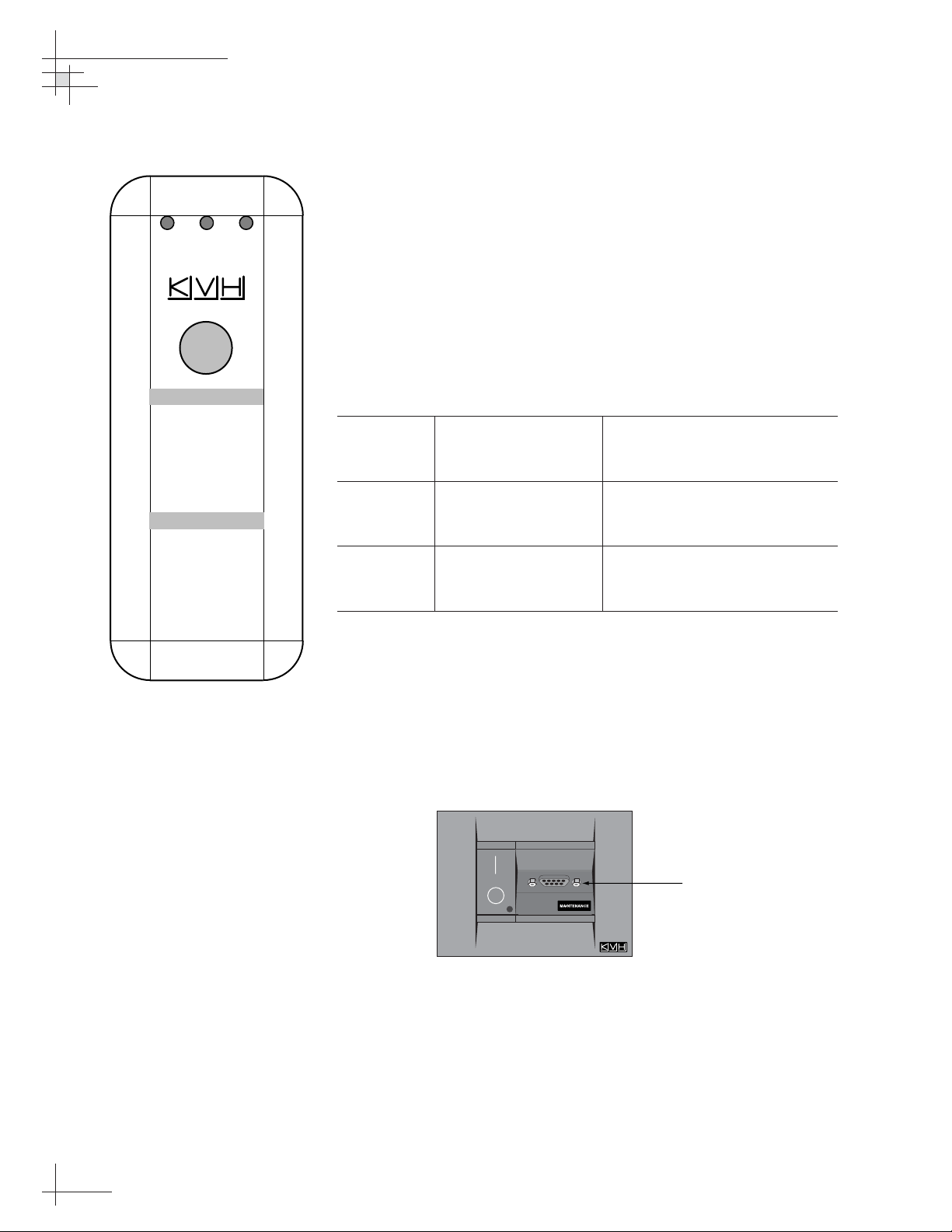
If you are unable to switch between satellites using the IRD
remote control, you can use the optional TV/SAT Switch (see
Figure 2-3) to easily select between Satellite A and Satellite B.
TV/SAT Switch Controls and Indicators
The Select button is used for all operator controls. The TV/SAT
Switch also has three LED indicators that show its current status.
Table 2-1 explains the function of each indicator.
Indicator Status Meaning
Sat A Blinking green Wait – Searching for satellite
Solid green Tracking Satellite A
Error Blinking red System problem – Refer to
Section 3, “Troubleshooting,”
to find the possible cause
Sat B Blinking green Wait – Searching for satellite
Solid green Tracking Satellite B
Connecting the TV/SAT Switch
To use the TV/SAT Switch, you must first connect it to the
TracVision system.
1. Connect the TV/SAT Switch’s data cable to the
maintenance port on the switchplate (see
Figure 2-4).
2. The Sat A and Sat B indicators blink while the
system initializes.
3. Either the Sat A or Sat B indicator will turn solid
green, denoting which satellite is currently being
tracked.
54-0150-01
12
TracVision 4 User’s Guide
Figure 2-3
TV/SAT Switch
Figure 2-4
Switchplate Maintenance Port
Table 2-1
TV/SAT Switch LED Indicators
Error
Sat A
Changing Satellites:
1. Push Select button
2. Wait while Sat A or
B blinks green
3. Ready when Sat A
or Sat B stays
solid green
Other Indicators:
• Both blinking
green: initializing
• Error light
blinking red:
system problem
Sat B
Select
Maintenance Port
(DB9 Connector)
Page 14

Using the TV/SAT Switch
The TV/SAT Switch is controlled via the single Select button. To
select the second satellite, perform the following steps:
1. Press the Select button on the TV/SAT Switch.
2. The indicator for the current satellite (Sat A or
Sat B) extinguishes, while the indicator for the
other satellite starts blinking.
3. Once the indicator for the other satellite turns
solid green, the TracVision system is tracking the
newly selected satellite. You can now use your IRD
to choose a channel on the new satellite.
Using a PC to Switch Between Satellites
If you’re unable to switch between satellites using the IRD
remote control, and you don’t have a TV/SAT Switch, you can
use a PC connected to the maintenance port. The procedure
requires terminal emulation software such as Windows
Hyperterminal. Use the settings appropriate to your application.
To switch satellites using a PC, perform the following steps:
1. Connect one end of the PC data cable to the DB9
connector on the switchplate. Connect the other
end to the serial port on your PC (a 9-pin/25-pin
connector adapter may be needed for some PCs).
2. Open the terminal emulation software and
establish the following settings:
• Bits per second: 9600
• Data bits: 8
• Parity: None
• Stop bits: 1
• Flow control: None
3. Once the data connection is made, enter the
Satellite Selection command as follows:
Command: @L,A or B<cr>
(<cr> indicates a carriage return/ENTER key)
Where: A = track Satellite A
B = track Satellite B
4. The antenna unit shifts to track the second
satellite.
Using Your TracVision 4
54-0150-01
13
Page 15

2.4 Watching Television
TracVision 4 allows you to watch satellite TV whether your vessel
is in motion or at rest.
Cable Unwrap
The antenna can rotate a full 720° before reaching the end of its
cable. If it does so, the system automatically unwraps the cable
by quickly rotating the dish in the opposite direction. During this
time, your television transmission will freeze momentarily while
the cable unwraps and the antenna reacquires the satellite.
Conical Scan Tracking
The antenna uses conical scanning to maintain peak signal
strength to the receiver and to update the satellite’s position.
When conical scan tracking is active, the antenna moves
continually in a circular motion to sweep across the satellite’s
peak signal. The signal strength is then fed back to the control
circuits to keep pointed in the direction of the strongest signal.
If the satellite signal is lost while the system is in conical scan
track mode, the control software imposes a 45-second time-out
delay. If the signal is not regained during that time, the antenna
will search for the satellite signal. This is an automatic process
that does not require user intervention.
Sleep Mode
When the vessel has come to a stop and holds its position for one
minute (e.g., at a dock), the antenna unit enters Sleep Mode,
which locks the antenna in place to conserve power. As soon as
the vessel moves beyond a 1° - 2° window, or the RF level
changes significantly, Sleep Mode automatically turns off and the
system begins tracking the satellite again (or enters Search mode
to find the satellite).
KVH recognizes that some customers may not want to take
advantage of this convenient feature. In this case, it is possible to
disable Sleep Mode using a simple software command as follows:
1. Connect a laptop computer to the system using the
maintenance port and a terminal emulation
program, as described in “Using a PC to Switch
Between Satellites” on the previous page.
54-0150-01
14
TracVision 4 User’s Guide
Page 16

2. Turn on the antenna. When the limit switch test is
complete:
a. Type HALT<cr> (<cr> indicates a carriage
return/ENTER key).
b. Type DEBUGON<cr>.
c. Type SLEEPOFF<cr>.
3. Cycle the antenna’s power. Sleep Mode is now
disabled.
4. To reactivate Sleep Mode, follow this same
process, except type SLEEPON<cr> in Step c.
2.5 Internet Access
Your TracVision 4 can receive high-speed Internet data when
used in conjunction with KVH’s TracNet 2.0 Mobile High-speed
Internet System. With TracNet 2.0, you get broadband Internet
access on the move via satellite downloads and a wireless return
path. For more information about TracNet 2.0 in North America
and Europe, please visit our web site at www.kvh.com.
Using Your TracVision 4
54-0150-01
15
Page 17

Troubleshooting
54-0150-01
17
3 – Troubleshooting
This section identifies basic trouble symptoms and lists their possible
causes and solutions.
Contents
3.1 Troubleshooting Matrix . . . . . . . . . . . . . . . . . . . . . . . . . . . . . . . . . . . .19
3.2 Causes and Remedies for Common
Operational Issues . . . . . . . . . . . . . . . . . . . . . . . . . . . . . . . . . . . . . . .20
3.3 IRD Troubleshooting . . . . . . . . . . . . . . . . . . . . . . . . . . . . . . . . . . . . . .23
3.4 Antenna Gyro and LNB Faults . . . . . . . . . . . . . . . . . . . . . . . . . . . . . . .23
Page 18
Troubleshooting
54-0150-01
191919
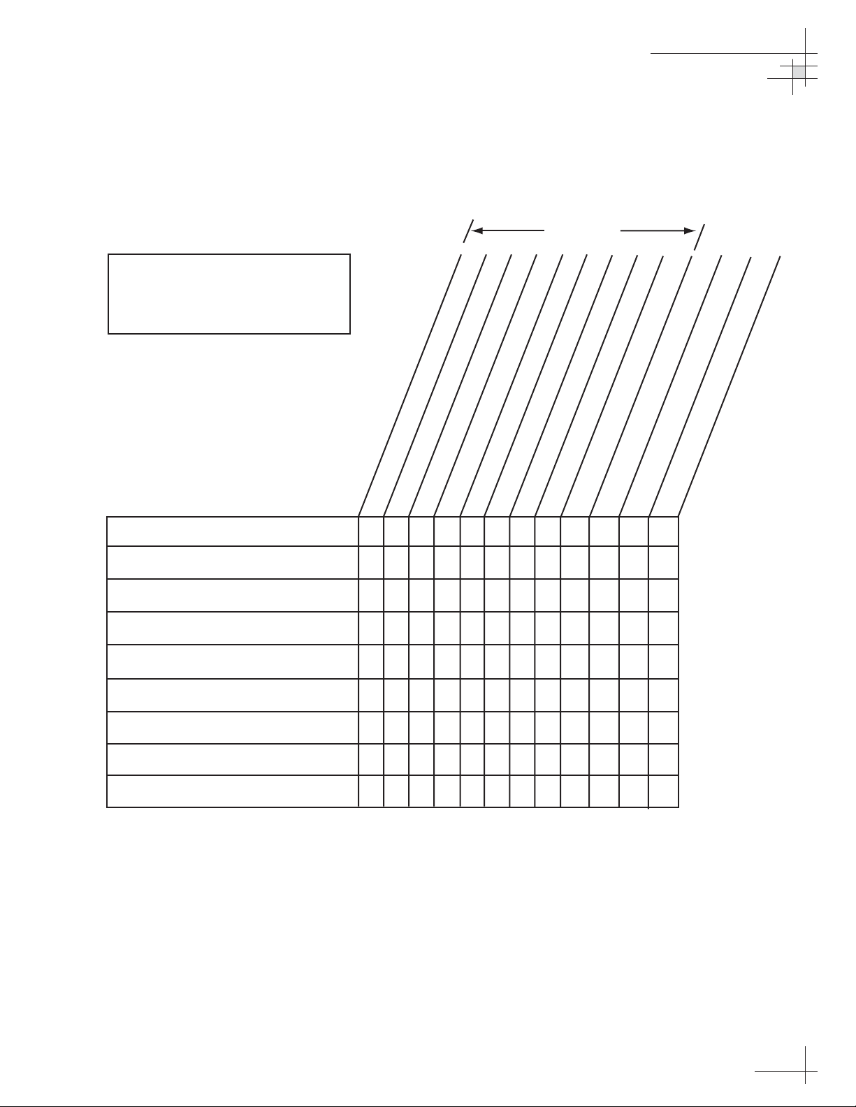
3.1 Troubleshooting Matrix
The troubleshooting matrix shown in Table 3-1 identifies some
trouble symptoms, their possible causes, and references to
troubleshooting solutions.
Table 3-1
Troubleshooting Matrix
Section 3.2
Key
1 = Anyone can do
2 = Electronics know-how recommended
3 = Dealer service recommended
U
L
O
S
D
N
A
(
w
E
o
S
p
U
w
A
o
l
C
,
E
e
s
L
u
B
f
I
S
S
SYMPTOM
Antenna non-functional 1
Antenna not switching satellites 1 1 1 1 2 2 2 2
No picture on TV set 1 1 2 2 2 2 2
Certain channels do not work 1 1 1 3 2 2 2
Intermittent picture for short intervals 1 1 1 2 2 2 3 2
O
P
l
n
e
s
w
s
o
l
e
B
V
g
n
i
)
r
i
N
w
O
I
r
e
T
p
o
r
p
m
i
r
o
,
r
e
g
n
i
r
u
d
g
n
i
n
r
t
u
t
c
e
r
r
o
c
n
I
n
o
p
i
t
u
t
a
r
r
u
a
t
g
i
s
f
n
o
c
e
t
i
l
l
l
a
e
t
n
a
g
i
s
s
e
t
i
l
l
e
t
a
S
S
e
d
u
e
s
k
s
i
c
o
l
b
c
e
t
i
l
l
e
t
a
e
e
c
g
n
a
e
r
r
e
e
f
v
r
o
R
e
r
e
f
t
n
e
i
t
i
l
r
l
a
e
t
d
a
a
S
d
s
r
e
o
g
t
n
c
a
e
h
n
c
n
a
t
a
d
y
c
n
e
o
u
o
l
q
r
o
t
c
e
r
r
o
c
y
n
I
T
d
o
e
c
F
R
e
i
s
w
s
i
t
l
u
m
f
o
e
p
r
s
e
u
p
h
o
r
c
t
p
m
i
r
o
y
t
l
a
u
n
a
n
f
e
t
D
n
R
I
A
)
3
.
3
n
o
i
t
c
e
S
(
d
e
r
u
g
i
f
n
n
o
o
i
t
c
c
y
e
l
S
(
y
t
l
u
a
f
o
b
r
y
m
g
e
s
s
a
B
N
L
)
)
4
.
4
.
3
3
n
o
i
t
c
e
S
(
y
t
l
u
a
f
y
l
System works at dock but not on the move 1 3
System will not find satellite 11111232 2 2 3 2
Snowy television picture 1 2 2
Pixelating television picture 1 1 2 2 2 3 2
Page 19

54-0150-01
20
TracVision 4 User’s Guide
2020
3.2 Causes and Remedies for
Common Operational Issues
There are a number of common issues that can affect the signal
reception quality or the operation of the TracVision 4. The
following sections address these issues and potential solutions.
Blown Fuse, Low Power, or Wiring
If the antenna unit is installed but entirely non-responsive, there
are three key factors to check as part of the troubleshooting
process:
Blown Fuse
With the system powered on, move the antenna
reflector slowly by hand. If the reflector does not
move freely, a fuse is not the problem. If the
reflector does move freely, one of the two fuses
mounted on the CPU Board may have blown or
been broken. The TracVision 4 Technical Manual
provides detailed instructions for authorized
service personnel who may be required to replace
a fuse. Contact your local KVH dealer or service
center for assistance.
Low Power
If the power cable to the antenna unit is more than
50 ft (15 m), the power levels can decrease over the
course of the cable, resulting in a voltage or
current level at the antenna unit that is too low to
power the system properly. The TracVision 4
Technical Manual provides detailed instructions for
supplying adequate power to the antenna unit.
Contact your local KVH dealer or service center
for assistance.
Wiring
If the system has been improperly wired, it will
not operate correctly. The TracVision 4 Technical
Manual provides detailed instructions for
authorized service personnel who may be required
to check the wiring. Contact your local KVH
dealer or service center for assistance.
If you need help troubleshooting
your system, please contact an
authorized KVH dealer. To find an
authorized dealer near you, visit
www.kvh.com, or contact KVH
directly at the numbers provided on
the first page of this manual.
Page 20

Troubleshooting
54-0150-01
212121
Vessel Turning During Startup
If the vessel turns during the 60-second startup and
initialization sequence that occurs immediately after turning
on the power to the TracVision 4, the antenna gyro will record
that variable motion as “standing still.” This may cause the
antenna to track improperly. To solve this problem, turn
TracVision 4 off for at least 10 seconds. Turn the system back
on, making certain that the vessel is either motionless or
traveling in a straight line for the 60 seconds immediately
following power-up.
Incorrect Satellite Configuration
(European Systems Only)
The satellite configuration on European IRDs must match the
satellite settings on the TracVision 4 system.
• Satellite A on the TracVision 4 must be the same
satellite as IRD Alternative 1 (or A, based on your
IRD) and must be assigned the IRD DiSEqC 1
setting.
• Satellite B on the TracVision 4 must be the same
satellite as IRD Alternative 2 (or B, based on your
IRD) and must be assigned the IRD DiSEqC 2
setting.
Refer to your IRD user manual for complete instructions on
configuring your IRD.
Satellite Signal Blocked
Satellite signals can be blocked or degraded by buildings, other
vessels, or equipment on the vessel itself. Simpy moving the
vessel or obstruction will clear the signal.
Satellite Coverage Issue
TracVision 4 will provide outstanding reception within the
18" (45 cm) antenna coverage area for your satellite television
service of choice. However, reception can be degraded as you
approach the fringe coverage areas. Refer to your satellite
television service manual to check the viable coverage area for a
18" (45 cm) antenna.
For your convenience, KVH
provides links to several web sites
that offer satellite coverage
information. Simply go to our web
site at www.kvh.com/footprint.
Page 21

54-0150-01
22
TracVision 4 User’s Guide
2222
Radar Interference
The energy levels radiated by radar units can overload the
antenna’s front-end circuits. Check with your installer to make
certain that the TracVision 4 antenna unit is in the optimal
location with regard to your radar unit.
Satellite Frequency Data Changed
If some channels work while one or more other channels do not,
or if the antenna is unable to find the satellite, the selected
satellite’s frequency data may have changed. This frequency data
can be updated via the maintenance port. Contact your local
KVH dealer or service center for assistance.
Incorrect or Loose RF Connectors
A loose RF connector can reduce the quality of the satellite signal.
Also, if you cannot switch satellites using your IRD remote, your
IRD may be connected to the wrong antenna baseplate connector.
The TracVision 4 Technical Manual provides instructions for
authorized service personnel who may need to check the RF
connections. Contact your local KVH dealer or service center for
assistance.
Type of Multiswitch Used
(North American Systems Only)
An active (not passive) multiswitch must always be used to
connect the TracVision 4 system to multiple IRDs. Contact your
KVH dealer or service center for assistance.
Page 22

Troubleshooting
54-0150-01
232323
3.3 IRD Troubleshooting
The IRD that was provided with your satellite television service
may also be the cause of less-than-ideal operation. First check the
IRD’s configuration to ensure it is set up for the desired
programming. In the case of a faulty IRD, refer to your IRD
user’s manual for service and warranty information. If the IRD is
both configured properly and fully functional, contact your local
KVH dealer or service center for assistance.
3.4 Antenna Gyro and LNB Faults
The TracVision 4 Technical Manual provides detailed instructions
for authorized service personnel who may be required to replace
the antenna’s gyro or Low Noise Block (LNB). Contact your local
KVH dealer or service center for assistance.
Page 23

KVH Industries Limited Warranty
TracVision 4
Limited Warranty on Hardware
KVH Industries, Inc. warrants the KVH product purchased against defects in materials for a period of TWO (2) years
and against factory labor costs for a period of ONE (1) year from the date of original retail purchase by the original
purchaser. It is the customer’s responsibility to verify the date of purchase by returning the warranty card included with
the product to KVH within 30 days of purchase, or by providing a copy of a dated sales receipt for the KVH product
under warranty with the warranty claim. If this date cannot be verified, the warranty period will begin 30 days after the
date of manufacture of the original product purchased.
If you discover a defect, KVH will, at its option, repair, replace or refund the purchase price of the product at no charge
to you, provided you return it during the warranty period, transportation charges prepaid, to the factory direct. Please
attach your name, address, telephone number, a description of the problem and a copy of the bill of sale or sales
receipt as proof of date of original retail purchase, to each product returned to warranty service. Alternatively, you may
bring the product to an Authorized KVH dealer/distributor for repair. During the first year, and if the product was
installed by an Authorized KVH dealer/distributor (identified with the KVH Authorized dealer/distributor list), KVH will
cover the dealer’s/distributor’s labor charges for warranty repairs, provided the dealer/distributor contacts KVH for preapproval of the charges. Approval of charges is at KVH’s sole discretion.
This Limited Warranty does not apply if the product has been damaged by accident, abuse, misuse or misapplication
or has been modified without the written permission of KVH; if any KVH serial number has been removed or defaced;
or if any factory-sealed part of the system has been opened without authorization.
Return Authorization
A Return Material Authorization is required prior to returning the product to KVH Industries. Please call our Technical
Support Department at +1 401 847-3327 or send an e-mail to [email protected] to obtain the RMA number. Write the
number in large, clear characters on the outside of the box. To avoid confusion and misunderstandings, shipments
without an RMA number clearly visible on the outside box will be refused and returned to you at your expense. If
possible, use the original box and packing material to protect the equipment from damage in shipment. KVH assumes
no responsibility for warranty shipments from the customer to the factory if not shipped in the manner prescribed
above.
THE EXPRESS WARRANTIES SET FORTH ABOVE ARE THE ONLY WARRANTIES GIVEN BY KVH WITH
RESPECT TO ANY PRODUCT FURNISHED HEREUNDER; KVH MAKES NO OTHER WARRANTIES, EXPRESS,
IMPLIED OR ARISING BY CUSTOM OR TRADE USAGE, AND SPECIFICALLY DISCLAIMS ANY WARRANTY OF
MERCHANTABILITY OR OF FITNESS FOR A PARTICULAR PURPOSE. SAID EXPRESS WARRANTIES SHALL
NOT BE ENLARGED OR OTHERWISE AFFECTED BY TECHNICAL OR OTHER ADVICE OR SERVICE PROVIDED
BY KVH IN CONNECTION WITH ANY PRODUCT.
KVH's liability in contract, tort or otherwise arising out of or in connection with any product shall not exceed the price
paid for the product. IN NO EVENT SHALL KVH BE LIABLE FOR SPECIAL, PUNITIVE, INCIDENTAL, TORT OR
CONSEQUENTIAL DAMAGES OR LOST PROFITS OR GOODWILL (INCLUDING ANY DAMAGES RESULTING
FROM LOSS OF USE, DELAY IN DELIVERY OR OTHERWISE) ARISING OUT OF OR IN CONNECTION WITH THE
PERFORMANCE OR USE OR POSSESSION OF ANY PRODUCT, OR ANY OTHER OBLIGATIONS RELATING TO
THE PRODUCT, EVEN IF KVH HAS BEEN ADVISED OF THE POSSIBILITY OF SUCH DAMAGES.
If any implied warranty, including implied warranties of merchantability and fitness for a particular purpose, cannot be
excluded under applicable law, then such implied warranty shall be limited in duration to ONE (1) YEAR from the date
of the original retail purchase of this product by the original purchaser.
Some states/countries do not allow the exclusion or limitation of implied warranties or liability for incidental or
consequential damages, so the above limitations may not apply to you. This warranty gives you specific legal rights,
and you may also have other rights which vary from state/country to state/country.
Page 24

KVH Industries, Inc.
50 Enterprise Center Middletown, RI 02842-5279 U.S.A.
Phone: (401) 847-3327 Fax: (401) 849-0045
E-mail: [email protected] Internet: www.kvh.com
KVH Europe A/S
Kokkedal Industripark 2B 2980 Kokkedal Denmark
Phone: +45 45 160 180 Fax: +45 45 160 181
E-mail: [email protected] Internet: www.kvh.com
KVH®and TracVision®are registered trademarks of KVH Industries, Inc.
TV4_UG_Cover.0604
®
 Loading...