

Page 1

Installation Guide
PCAM-CHMSL2-FD99
Third Brake Light Camera
with Cargo and Side Blind Spot Views
Ford Super Duty Trucks (1999-2016)
Page 2

Installation Guide
PCAM-CHMSL2-FD99
Third Brake Light Camera
Thank you for purchasing your EchoMaster Pro automotive camera.
EchoMaster cameras are designed to improve safety while driving by
providing high quality images of surrounding areas and obstacles in the
vicinity of the vehicle. They will also improve vehicle maneuvering capability
by displaying blind spots not normally visible to the driver.
Please ensure you read and understand all aspects of this manual before
installing or using your EchoMaster camera.
Key Features
1/3” CMOS Sensor
Operates at 0.3 LUX
Water/debris proof rating: IP67
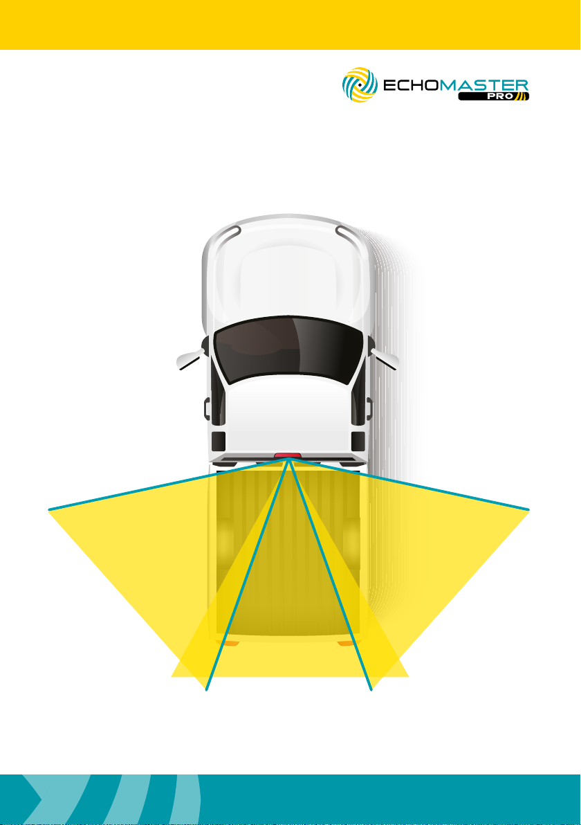
3 Viewing Angles
• Right 95°
• Left 95°
• Rear 90 °
2
Page 3
PCAM-CHMSL2-FD99
Third Brake Light Camera
Box Contents
Third Brake Light Camera and Bracket
17.5’ Extension Cable
2 Phillips Mounting Screws
Camera Adjustment Tool
Installation Guide
Warranty Card
Installation Guide
Illustrations are typical and may not match exact vehicle details.
32
Page 4
Installation Guide
Installing the CHMSL Camera
Step 1
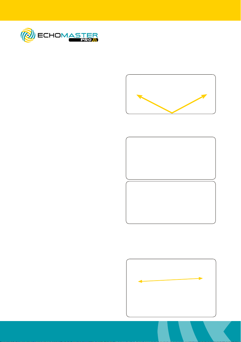
Remove the 2 screws that secure the third
brake light.
Step 2
a. Remove the third brake light from the
vehicle and disconnect connector.
PCAM-CHMSL2-FD99
Third Brake Light Camera
b. Place the third brake light onto the third
brake light camera bracket and line up the
screw holes.
c. Reconnect the third brake light to the
factory connector.
Step 3
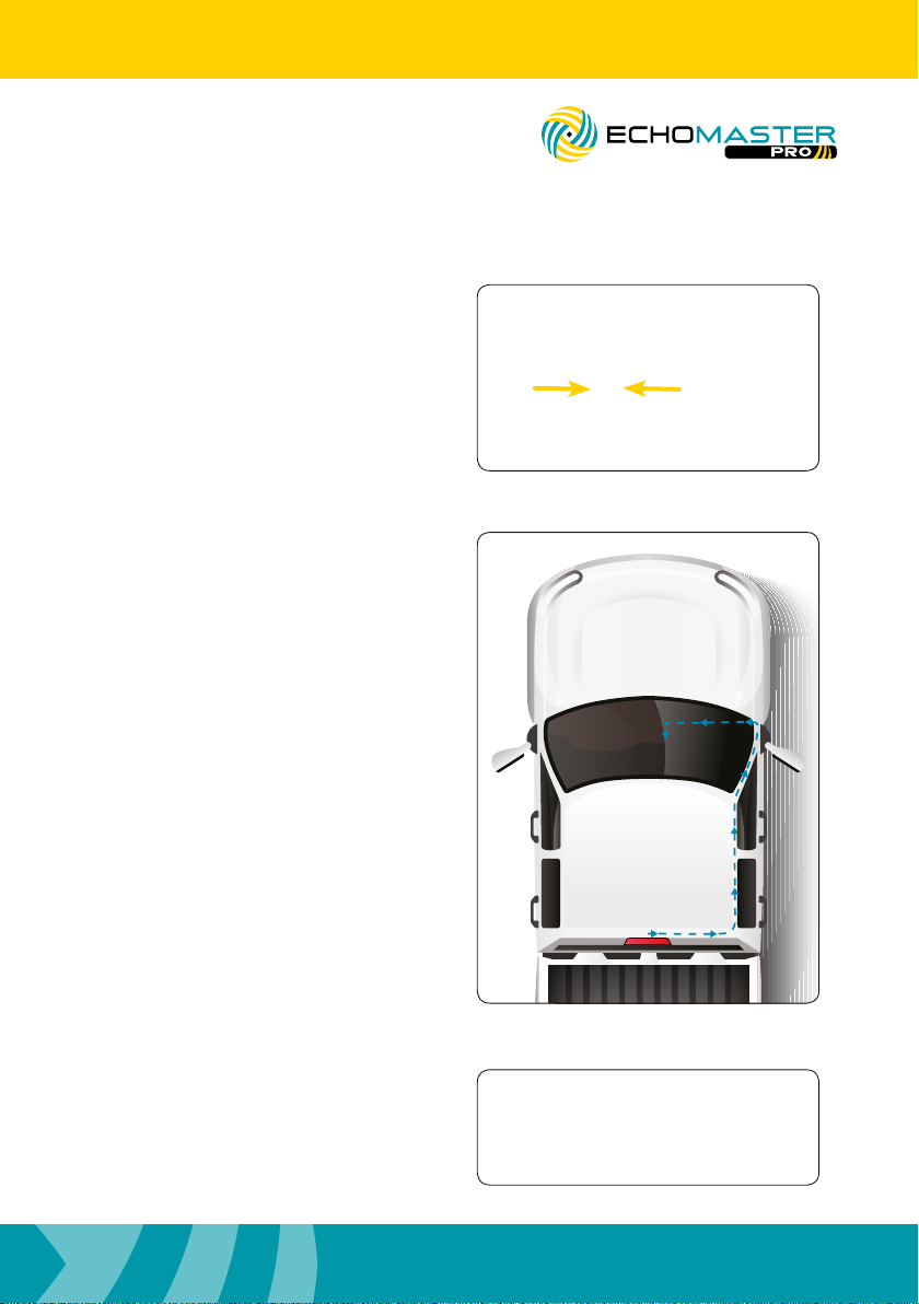
Using a long zip tie or sh tape with the
camera cable attached to it, feed the
camera cable from the third brake light
opening into the vehicle and towards the
b / c pillar to the right or the left. (The
weather seal may need to be removed to
gain access to the sh tool used to run
the cable.)
4
Page 5
PCAM-CHMSL2-FD99
Third Brake Light Camera
Step 4
Connect the extension cable to the
camera.
Installation Guide
Step 5
Route the cable to the front of the
vehicle and behind the radio, monitor, or
mirror monitor.
Step 6
Remount third brake light and
camera assembly using the longer
mounting screws provided in the kit.
54
Page 6
Installation Guide
PCAM-CHMSL2-FD99
Third Brake Light Camera
Step 7
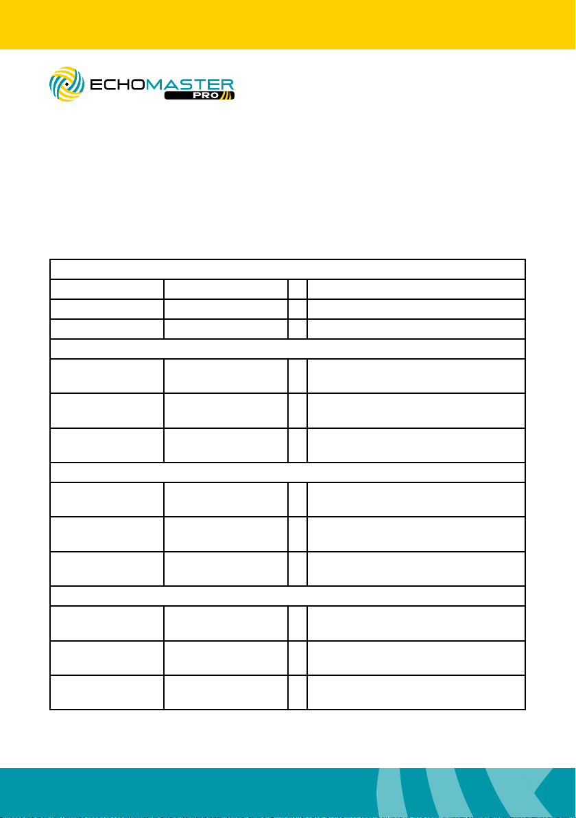
Route the reverse and turn signal wires to their respective locations according to the
table below
1999 - 2001
Turn Signal (Left) Light Green / White + Turn signal switch
Turn Signal (Right) White / Lt. Blue + Turn signal switch
Reverse Light Black / Pink + Under hood relay box
2002 - 2007
Turn Signal (Left) Light Green / White + Turn signal switch, Gray 12 pin plug,
pins 10
Turn Signal (Right) White / Light Blue + Turn signal switch, Gray 12 pin plug,
pins 7
Reverse Light Black / Pink + Dash fuse box, rear, Black 8 pin plug
(G), pin 1
2008 - 2010
Turn Signal (Left) Blue / Green + SJB in passenger kick, Black 26 pin
plug, pin 21
Turn Signal (Right) Yellow / Violet + SJB in passenger kick, Black 26 pin
plug, pin 23
Reverse Light Green / Brown + Under steering column to left, Black
59 pin plug, pin 41
2011 - 2016
Turn Signal (Left) Blue / Green + BCM in passenger kick, Green 26 pin
plug, pin 8
Turn Signal (Right) Yellow / Violet + BCM in passenger kick, Green 26 pin
plug, pin 7
Reverse Light Blue / White + BCM in passenger kick, 32 pin plug,
pin 13
6
Page 7

PCAM-CHMSL2-FD99
Third Brake Light Camera
Step 8
Connect the yellow video RCA to the
rear camera input on the radio, monitor,
or mirror monitor.
Step 9
Connect the Blue “Reverse power
anode output” wire to the reverse trigger
input on the radio, monitor, or mirror
monitor.
Installation Guide
Step 10
With the ignition in the on position, shift
the vehicle into reverse.
Step 11
Using the supplied tool, adjust the
camera’s view to desired position. (Keep
in mind that this adjustment will effect
the blind spot view. It may be necessary
to trigger the blind spot view to conrm
desired position.)
76
Page 8

Installation Guide
Using the CHMSL Camera
Using the CHMSL Camera
Rear Cargo View Camera
With the ignition in the on position, shift
the vehicle into reverse. The image should
appear on the screen.
PCAM-CHMSL2-FD99
Third Brake Light Camera
Left Blind Spot Camera
With the ignition in the on position, apply
the left turn signal. The image should
appear on the screen.
Right Blind Spot Camera
With the ignition in the on position, apply
the right turn signal. The image should
appear on the screen.
8
Page 9
PCAM-CHMSL2-FD99
Third Brake Light Camera
Views
Installation Guide
LEFT
95°
REAR
90°
RIGHT 95°
98
Page 10
Installation Guide
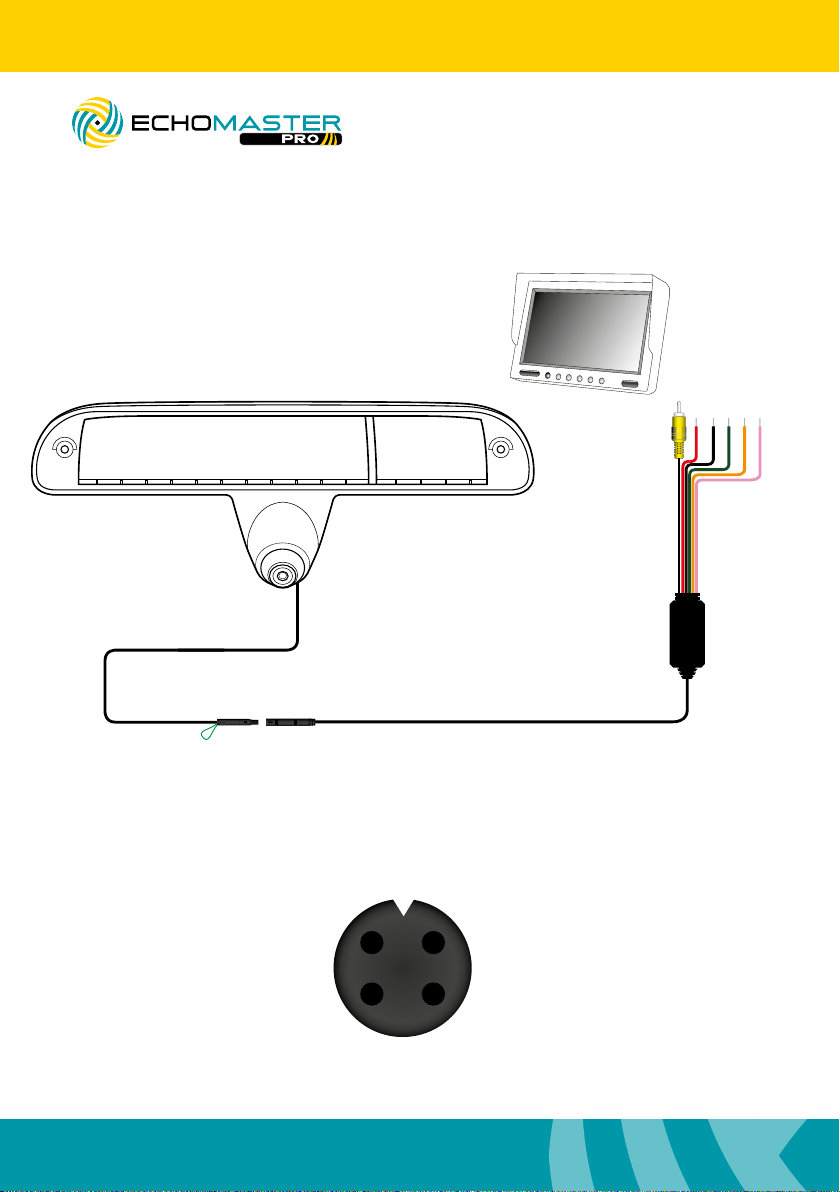
Wiring Diagram
PCAM-CHMSL2-FD99
Third Brake Light Camera
Video Output
Ground (Black)
Reverse Signal Input + (Green)
Right Turn Signal Input + (Orange)
Switched +12V (Red)
36in
Left Turn Signal Input + (Pink)
69 in
Parking Lines (Green) On - Joined (Default)
10
O - Cut
Video
1 2
174 in
GND
43
+12V
Page 11

PCAM-CHMSL2-FD99
Third Brake Light Camera
Notes:
Installation Guide
1110
Page 12

AGREEMENT: End user agrees to use this product in compliance with the instructions and terms of use
above and with all State and Federal laws. EchoMaster provides instructions and safety warnings with
respect to this product and disclaims all liability for any use not in conformity with those instructions
or other misuse of its product. If you do not agree, please discontinue use immediately and contact
EchoMaster. This product is intended for off-road use and passenger use only.
email - [email protected]
tel- 866-766-2267
Clearwater Florida 33760
EchoMaster is a Power Brand of AAMP Global
www.EchoMaster.com
PCAM-CHMSL-FD99
REV. 060619
 Loading...