

Page 1
Installation Guide
DVR-50(G)
1
5 Channel Digital Video Recorder
Installation Manual
Page 2

Installation Guide
DVR-50 (G)
5 Channel DVR Recorder
Contents
Introduction Page 6
- Key Features & Box Contents Page 6
Front Panel Layout Page 6
Dimensions Page 7
Installation Page 8
- DVR-50-TH (optional) Page 9
- DVR-50-TH Wiring Diagram Page 9
Initial Setup Page 10
Menu Page 10
- Main Menu Page 10
- Home Screen Page 11
- REC Search Page 12
- Log Search Page 12
- System Page 12
- Log Out Page 12
- Setup Page 12
- Basic Setup Page 13
- Regist Info Page 13
- Device Info Page 13
- Vehicle Info Page 13
- Driver Info Page 13
- Time Setup Page 13
- General Page 13
- Time sync Page 13
- DST Page 13
- Startup Page 13
- On/Off Page 13
- Mode Page 13
- Ignition Display Page 13
- Timer Page 13
- Light off time Page 13
2
Page 3

Installation Guide
DVR-50 (G)
5 Channel DVR Recorder
Contents
- Startup (continued) Page 14
- Sleep Page 14
- Sleep Mode Page 14
- Low Voltage protect Page 14
- Battery low voltage protect Page 14
- Voltage startup Page 14
- Low volt upload Page 14
- User Setup Page 14
- Idle Time Page 14
- Users Page 14
- Network, Application & Other Setup Page 14
- Surveillance Page 15
- Live View Page 15
- Preview Audio Page 15
- Image Setup Page 15
- Margins Page 15
- Startup screen Page 15
- Auto Loop Page 15
- Live OSD Page 15
- Record Page 16
- General Page 16
- System Page 16
- Overwrite Page 16
- Lock Duration Page 16
- Pre-recording Page 16
- Main Stream Page 16
- Channel Page 16
- Channel Name Page 16
- Enable Page 16
- Resolution Page 16
- Frame rate Page 16
- Quality Page 16
- Record Mode Page 16
- Preview Page 15
3
Page 4

Installation Guide
Installation Guide
DVR-50 (G)
5 Channel DVR Recorder
Contents
- Record Page 16
- Main Stream (continued) Page 16
- Audio Page 16
- Alarm Quality Page 16
- Encode Mode Page 16
- Resolution Page 16
- Frame rate Page 16
- Quality Page 16
- Record Mode Page 16
- OSD Page 17
- Position Page 17
- IPC Setup Page 17
- PTZ Page 17
- Dual Stream Page 17
- Collection Page 18
- General Page 18
- Sensor Page 18
- Sensor Number Page 18
- Overwrite Page 18
- OSD name Page 18
- Serial Port Page 18
- Speed Page 18
- Navigation Page 18
- Mileage Page 18
- Source Page 18
- Total Page 18
- Base Value Page 18
- Operation Page 18
- Snap Setting Page 18
- Alarm Page 19
- Base Page 19
- Speed Alarm Page 19
- Panel Alarm Page 19
- IO Alarm Page 19
4
Page 5

Installation Guide
DVR-50 (G)
5 Channel DVR Recorder
Contents
- Video Page 20
- Video Loss Page 20
- Motion Page 20
- Cover Page 20
- Advanced Page 21
- Acc Alarm Page 21
- Electrifence Page 21
- Maintenance Page 21
- Cong Page 21
- File Data Page 21
- Upgrade Page 21
- Storage Page 21
- Reset Page 21
Video Playback Page 22
References Page 23
- Storage Capacity Page 23
- Recording File Size Calculation Page 23
5
Page 6
Installation Guide
5 Channel DVR Recorder
Introduction
Thank you for purchasing the EchoMaster DVR-50 Digital Video Recorder (DVR).
This system is specically designed for vehicle video surveillance.
Box ContentsKey Features
DVR-50 (G)
u Up to 256GB of ash storage
u Quad analogue inputs
u HD 5th channel input
u Optional external trigger module (DVR-50-TH)
u Optional GPS (DVR-50-G)
u Lockable cover
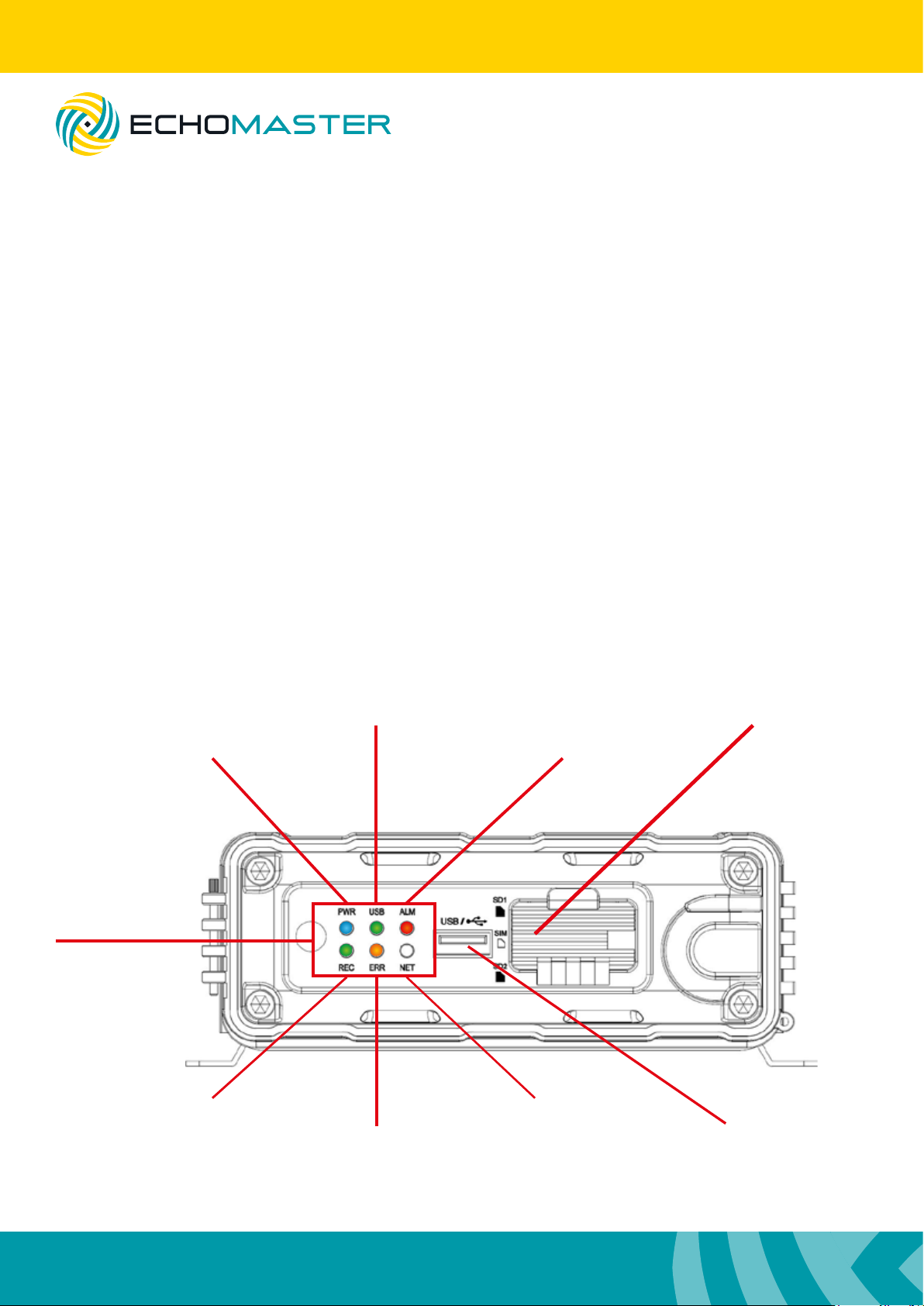
Front Panel Layout
USB dongle inserted
Power On
u DVR module
u GPS Antenna (DVR-50-G only)
u Power Cable
u GX16-RCA adapters x 5
u User Manual
SD Card Slots
Alarm Indicator
LED Indicators
Recording in progress
6
Operation Error
Network connected
USB Port
Page 7
DVR-50 (G)
5 Channel DVR Recorder
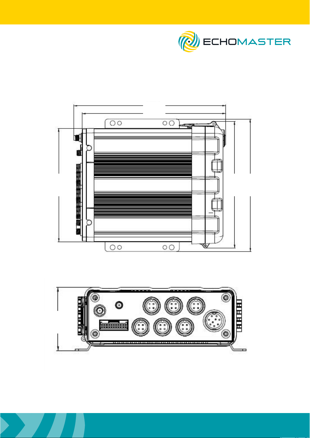
Dimensions (mm)
Installation Guide
167.3
157.8
125125
140.1
146.3
7
Page 8
Installation Guide
DVR-50 (G)
5 Channel DVR Recorder
Installation
When choosing a mounting location, please ensure that there is sufcient access to the front cover of the
DVR-50 to allow it to open.
Also ensure that there are no electrical or uid lines behind any panels that are to be drilled that could
become punctured.
Once the mounting location has been decided, secure the unit with 4 screws.
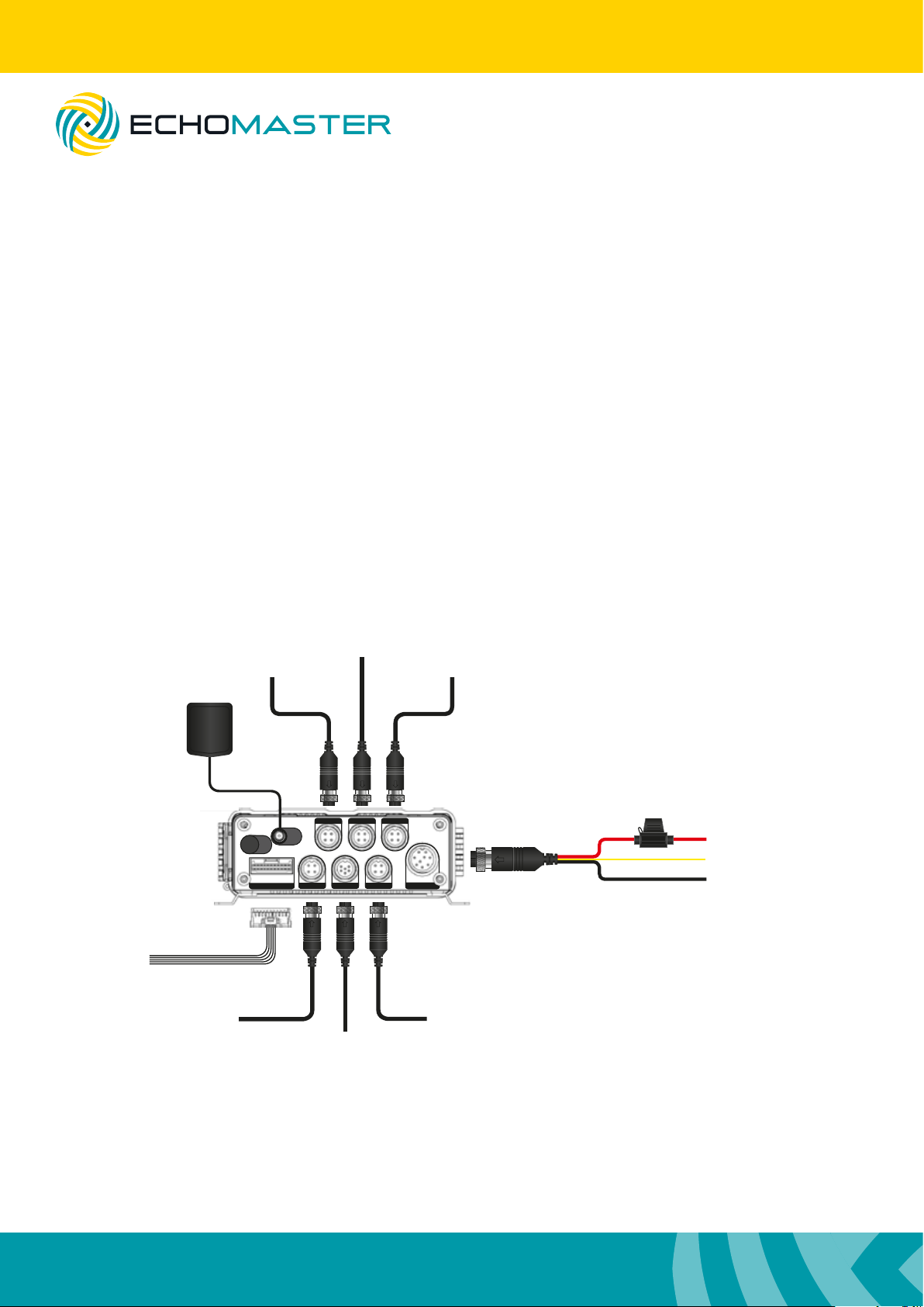
Connect the main power harness to +12V, IGN and Ground.
Make all camera connections before powering up the unit.
Connect and route the GPS antenna (DVR-50-G only) to a position where it has a clear and unobstructed
view of the sky. Any metalwork or large wiring looms above the antenna can obstruct its operation.
GPS Antenna
(DVR-50-G only)
DVR-50-TH
(optional)
A/V Out to Monitor
Camera CH1
GPS
Sensor & Serial
A/V OUT IPC
IPC Camera
Camera CH2
A/V IN 1 A/V IN 2 A/V IN 3
A/V IN 4
Camera CH3
POWER
Camera CH4
+12V
IGN
GND
(RED)
(YELLOW)
(BLACK)
8
Page 9
Installation Guide
DVR-50 (G)
5 Channel DVR Recorder
DVR-50-TH (optional)
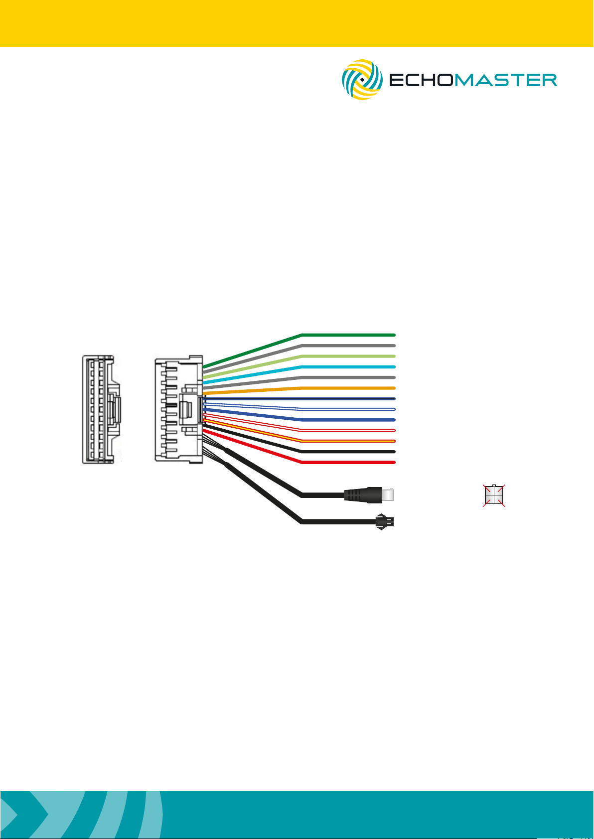
If using the DVR-50-TH then this should be connected at this time using the following instructions.
The DVR-50-TH adds the following functions to either the DVR-50 or DVR-50-G: 8 congurable trigger
inputs for external inputs, RS232 serial output, speed pulse input and an external mic input.
Follow the wiring diagram below for all connections.
DVR-50-TH Wiring Diagram
Trigger 1 In (Green)
1
2
21 22
Trigger 2 In
Trigger 3 In
Trigger 4 In
Trigger 5 In
Trigger 6 In
Trigger 7 In
Trigger 8 In
Speed In
Trigger 1 Out
Trigger 2 Out
GND Out
+5V Out
Mic
RS232
(Grey)
(Light Green)
(Light Blue)
(Grey)
(Orange)
(Blue/Black)
(Blue/White)
(Blue)
(Red/White)
(Red/Yellow)
(Black)
(Red)
MIC SW IN (3) MIC - (4)
MIC + (1) +5V (2)
Trigger IN 1- 8 can be a high or low trigger value which is congured in the menu of the DVR-50(G).
Trigger Out 1 and 2 can be used to trigger external devices (such as a telematics device) when any trigger
input is activated. This is again congurable in the DVR-50(G) menu.
Speed input can be used to record speed information of the vehicle onto the recording captured on the
DVR-50(G). It should be connected to the analog speed output wire on the vehicle (often found behind the
radio or instrument cluster).
RS232 output can be used to send and receive data from external devices.
The external mic input can be used to record separate audio to that of the mic normally housed in the
cameras.
9
Page 10

Installation Guide
DVR-50 (G)
5 Channel DVR Recorder
Initial Set-up
Power ON the unit with the door closed using the ignition.
Once it is powered up, open the door and plug a mouse into the USB port.
Right click the mouse and then click on the icon.
Use the password admin and click ‘LOGIN’
You will now have access to all the various features and settings of the unit.
Once initial setup is complete: unplug the mouse, insert the SD card(s), close and lock the door and you
are ready to start using the product.
Note:
It is always recommended to carry out a format on all SD cards using the internal format function
of the DVR before rst use.
Menu Function
Main Menu
Using a right mouse click you can bring up the main
options. With these initial options you are able to select
the individual channel display option or you are also
able to choose 2 different split screen display options
(4-way and 9-way split).
Note: that in the 9-way split screen view only the rst
5 channels will be displayed.
Playback of the most recent le is also possible from
this screen by selecting the playback option.
The BIZ Menu requires a different version and is not used in this product.
All congurable options are accessed by clicking the icon to bring up the home menu.
10
Page 11
DVR-50 (G)
5 Channel DVR Recorder
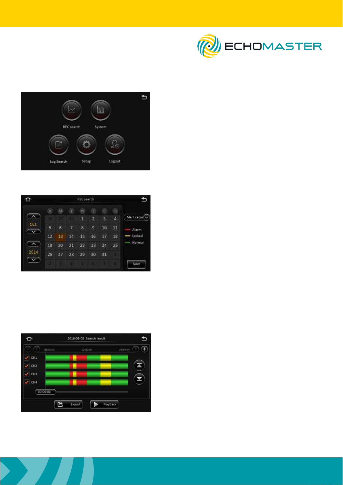
Home Menu
REC search
Installation Guide
When browsing the menu system you can return to the
previous menu by clicking the back arrow at the top right
of the screen.
Selecting the home icon from any menu will return you to
this screen.
Recordings can be searched for by date by selecting
the required date and clicking next.
You will note that the color displayed under the date
signies what type of recordings are present (normal
recording, locked recording and alarm recording).
You can also lter recordings by the recording type
and also the recording source (Main, sub or mirror).
Once a date has been selected there are options displayed for selecting specic video types (all, normal
or alarm). You can also select which channel to view (channels without recorded data are greyed out).
Clicking search will provide the option to search by time and also channel (multiple channels can be
selected). Clicking the + or – buttons will zoom in on the time bar graph allowing for very accurate time
selection while clicking the < or > icons will scroll up or down the graph. You can also select the exact
time to start playback by clicking on the time counter and entering the exact time.
Once you have chosen your start time, click playback
to start the playback of the recording.
Files can also be exported to a USB device in either a
comprehensive .264 or .avi format which may be more
easily read by certain devices.
When selecting to export a le you are given the option
to choose the start and end time for export.
11
Page 12
Installation Guide
DVR-50 (G)
5 Channel DVR Recorder
Log Search
This function will allow all operation or alarm logs to be viewed.
These are searched for in the same manner as video les with the user able to choose the date for
viewing and then the time. The option to view different log types is also given (alarm logs, operation logs
and locked logs).
Clicking search will then display the list of time stamped logs with the log type displayed next to it.
These will be shown in chronological order with the most recent displayed at the top of the list.
If the log is an alarm log then the related video le can be played by clicking the video icon to the right of
the le.
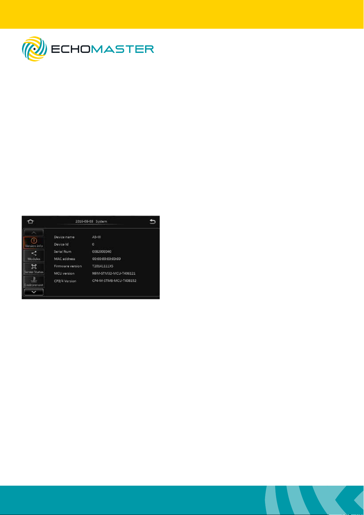
System
Clicking this icon will display all the relevant information
about the DVR including connected modules, server status,
DVR status (environment), and storage information.
Log Out
Click this to log out the current user.
Setup
In this menu all congurable options for the DVR can be set.
Note:
Please ensure that you click save in each screen after making any changes otherwise these changes
may not be saved.
12
Page 13
DVR-50 (G)
5 Channel DVR Recorder
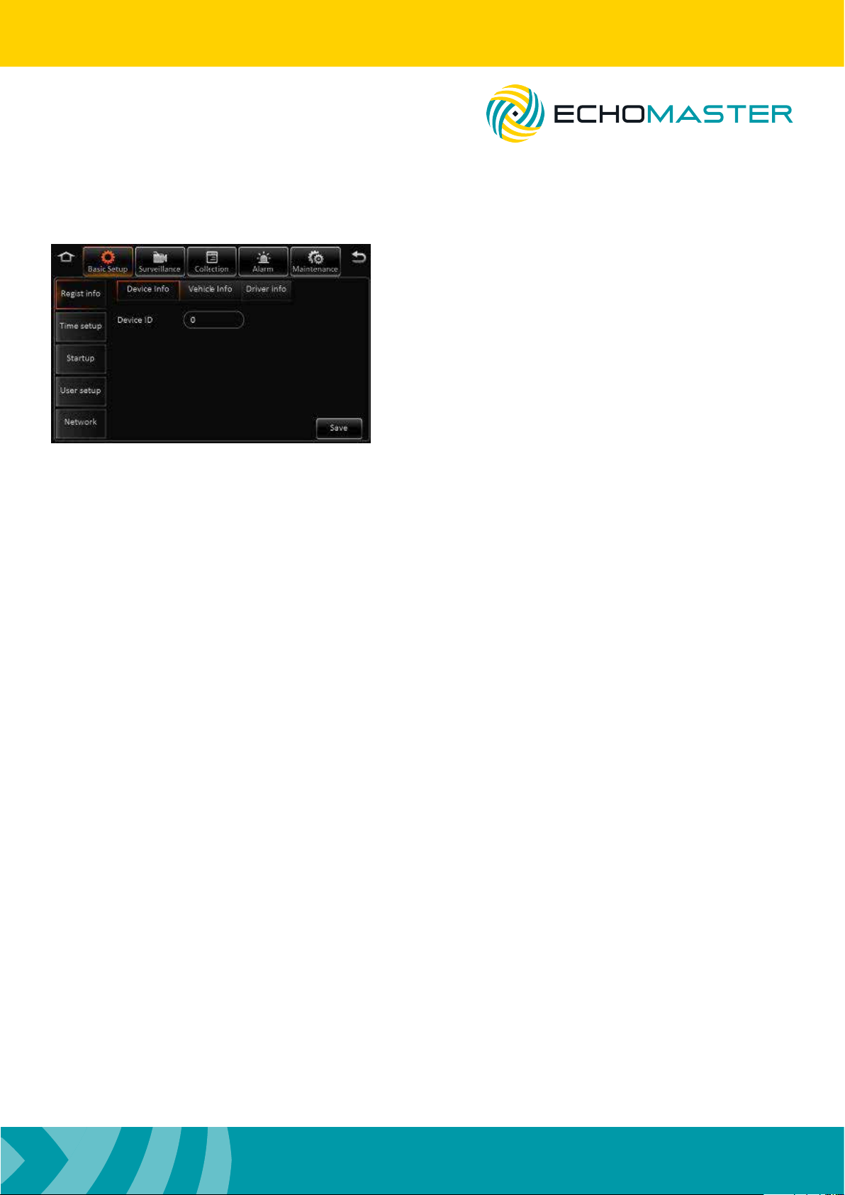
Basic Setup
Installation Guide
Regist Info
Device Info You can assign a number to the DVR to
distinguish it from others.
Vehicle info Vehicle plate – input the registration
number of the vehicle to which the device
is installed.
Vehicle number – Not required
Line Number – Not required
Driver info Driver number – Assign a unique number
to the driver of the vehicle if required
Driver name – Input the name of the driver
Time Setup
General This allows the user to set the date format, time format and time zone.
Time sync You can set the time and also choose whether the time will remain synced via
information received by GPS, server or NTP server.
DST It is also possible to congure DST settings.
Once enabled, you are able to set the DST.
Startup
On/Off Mode
Select whether to power cycle the unit according to ignition position, timer or
both ignition and timer.
Ignition delay
Select a delay period that the unit will continue recording after ignition has been
turned off (0-86399 seconds). Note that the timer will not begin countdown until 5
minutes have passed from the last power up.
Timer
Allows a specic power up and power down time to be set.
Light off time
Requires additional parts.
13
Page 14

Installation Guide
DVR-50 (G)
5 Channel DVR Recorder
Sleep Sleep Mode
Currently there is only one option available for no consumption standby.
Low voltage protect
When enabled, the unit will automatically shut down when the battery voltage
drops below the set level.
Battery low voltage protect
Sets the low voltage threshold for automatic shutdown.
Voltage startup
Sets the threshold for when the unit will boot up and return to normal operation.
Low volt upload
When enabled this will report low voltage incidents to the log.
User Setup
Idle time This function allows you to set the delay time that the screen will revert to the
camera image screen. If set to “never,” then the screen will always remain on the
current screen and never default back to the live view. This will also auto logout the
current user. If set to never then you will be required to log out manually by clicking
the logout icon in the main menu.
Users You can add, remove or edit users in this menu by selecting a current user
(to edit) or selecting add to enter a new user. This menu is where passwords can
be set for each user. Only Admin user can add new users (up to a maximum of 2
normal users).
Note: You cannot delete or rename the Admin user.
Admin user will have full access to all menus and setups whereas a normal user will not be able to change
any settings, but they will be able to search video and log les.
Network, Application & Other setup
These menus are only for use in products supporting network connections and have no function in this
product.
14
Page 15
DVR-50 (G)
5 Channel DVR Recorder
Surveillance
Installation Guide
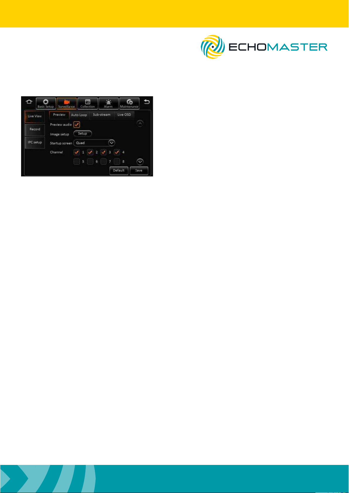
Live View
Preview Preview Audio
Selects whether the audio is heard in
the live view screen.
Image Setup
Allows adjustment for brightness, contrast,
color and saturation. These are individually
congurable for each channel. You can also
adjust the mirror image and vertical image
ip in this menu (again congurable for
each channel separately) by clicking on the
2 rotate icons. Settings can be copied from
1 channel to any other channel to save
making the same changes multiple times.
Margins Adjust the margins for the left, right, top and bottom of the screen to ensure that it
correctly ts your monitor.
Startup screen Set the default image display when the unit starts up (single image or split screen).
You can also choose which cameras to display in this split screen mode.
Auto loop You can congure the unit to automatically loop through any number of
video inputs. These can be displayed as a single image (1x1) quad screen (2x2)
or 9-way split screen (3x3).
Any combination can be chosen and the time that each image is displayed can be set independently for
each camera.
Live OSD
You are able to congure what information is displayed on the live view by ticking the required box.
Note: Not all options are available on all devices and some options require additional add on accessories.
15
Page 16

Installation Guide
DVR-50 (G)
5 Channel DVR Recorder
Record
General System
Allows the video output to be set as PAL or NTSC format.
Overwrite
The user is able to choose the manner in which data is overridden.
Capacity will overwrite data when the storage medium is full. Days will start
overwriting the storage medium after a set number of days (1-31). The ‘Never’
setting will not allow any data to be overridden (recording will be suspended when
the storage medium is full.)
Lock duration
This determines the length of time that locked les are retained before they will be
overwritten (1-31 days).
Pre-recording
If an alarm is triggered this setting denes the length of pre-recorded time that is
locked. Sets the threshold for when the unit will boot up and return to normal
operation.
Main Stream Channel Choose which channel to carry out settings on.
Channel Name Assign a specic name to that channel.
Enable Turn the channel on or off.
Resolution Set the recording resolution of the particular channel.
Frame rate Set the desired frame rate for the chosen channel.
Quality Choose the recording quality (1 is highest).
Record Mode This can set the mode in which recording is started on that
particular channel. Power up will start recording as soon as
the device is turned on. Timer will only start recording on that
particular channel at specic times which can be set after this
option is highlighted and alarm which will only record that
channel when an alarm is triggered.
Audio Allows audio to be recorded from any channel.
Alarm quality This can change the recording quality to a different level than
that of non-alarm recording. This means that the recording
level can be set to a lower quality to conserve storage space
but then switch to a higher quality when an alarm is triggere
Encode mode Choose whether les are encoded at variable bit rate (VBR) or
constant bit rate (CBR). You are able to copy the settings from
one channel to all others, or selected channels by using the
copy function.
16
Page 17

Installation Guide
DVR-50 (G)
5 Channel DVR Recorder
Dual Stream This allows a separate recording stream to be enabled. This can be set to be a
mirrored recording, a sub-recording of certain channels or a recording of alarm
channels.
This can be saved to only the internal storage medium as the external SD card has
no function in this version. In mirror recording, all video parameters are set to be
the same as the main recording stream. In sub-recording you can congure separate
parameters for each channel which are independent of the main recording stream.
OSD You are able to choose what information is shown on the recorded videos by
ticking the required parameter.
Position The position on screen where the relevant pieces of information can
be changed by clicking this button. You will then be shown a single
image with all of the information selected shown. Click and drag the
information to the desired area and click save.
IPC Setup
Congure all settings when using the IPC HD cameras. Please ensure that the IPC camera is connected
before conguring any of these options.
Channels 1-3 are reserved for analog cameras and cannot be assigned to an IPC camera, but either channel 4 or 5 can be used to display the video from a connected IPC camera. Select the desired channel by
ticking the relevant box.
Once ticked, you should click the search icon for the relevant channel. The unit will then perform a search
for a connected IPC camera. Once the camera has been found, the results will be displayed. Select the
camera by ticking the check box and click OK.
There will now be an IP address and port number displayed on the main IPC setup screen. Click save and
the camera image should now be able to be viewed in the live view.
PTZ
If using a PTZ camera then this menu can congure the various settings and protocols for control.
You are also able to test the functionality in this menu.
17
Page 18
Installation Guide
Collection
DVR-50 (G)
5 Channel DVR Recorder
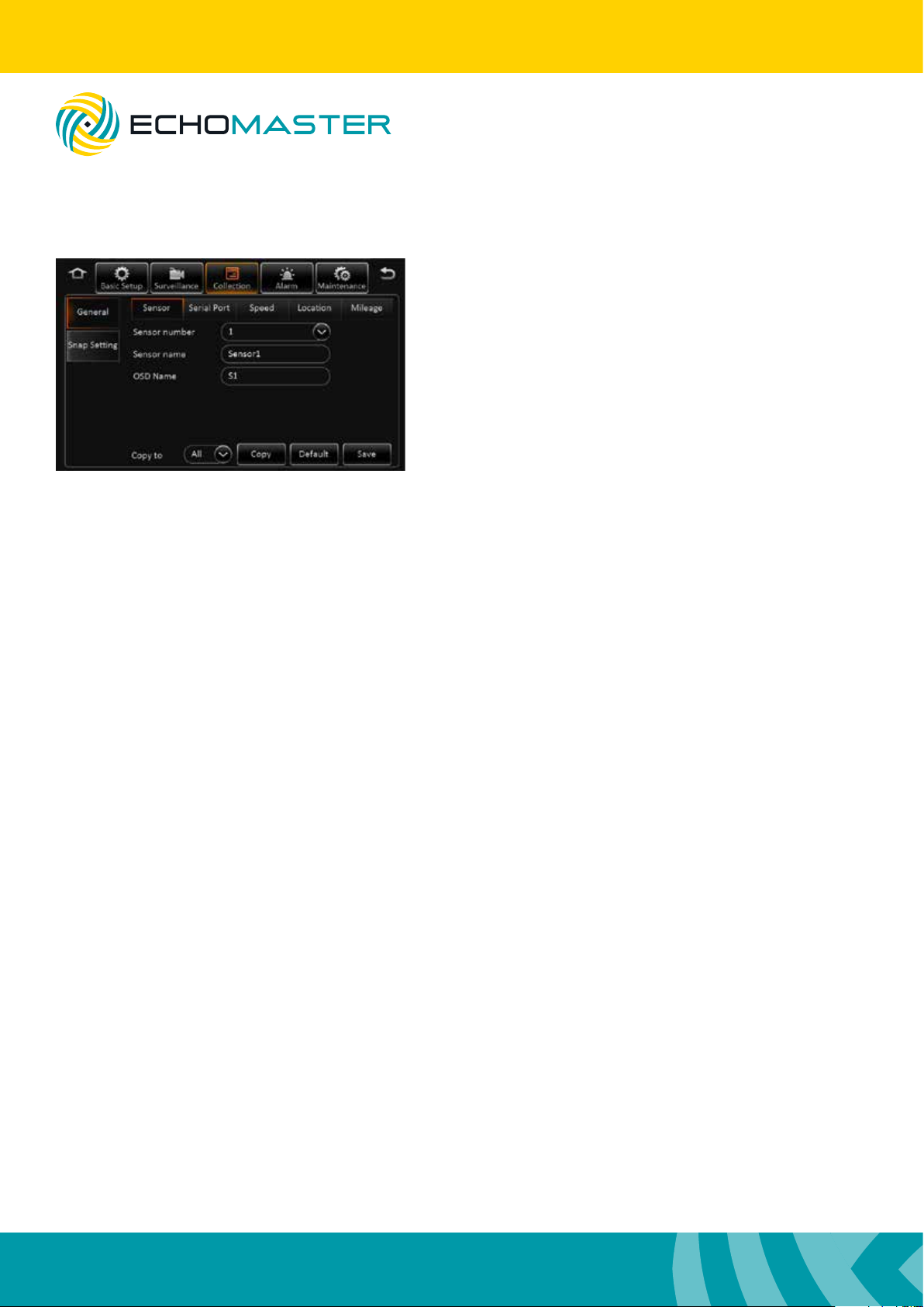
General
Sensor Sensor Number
Choose which sensor you wish to
edit.
Overwrite
Assign a specic name to the
chosen sensor
OSD name
Assign a certain name that will be
displayed on screen when a sensor
is activated.
Serial port This allows you to congure all functions for the RS232 serial port when using
external devices, including the type of device connected and also the baud rate.
Speed In this menu, the speed unit and source of the speed information can be congured.
Navigation Currently can only be set to GPS.
Mileage Source You are able to select the source of the mileage information.
Total Displays the total miles covered since last reset.
Base Value This is the initial starting value for the mileage counter when reset.
This can be useful if swapping out units as the mileage counter from
the old unit can be inserted into this column to retain an accurate
record.
Operation Clicking correct will adjust the mileage counter to that of the number
entered into the base value. Clicking clear will reset the mileage
counter to zero.
Snap Setting
This menu has no function in this product.
18
Page 19
DVR-50 (G)
5 Channel DVR Recorder
Alarm
Installation Guide
Base
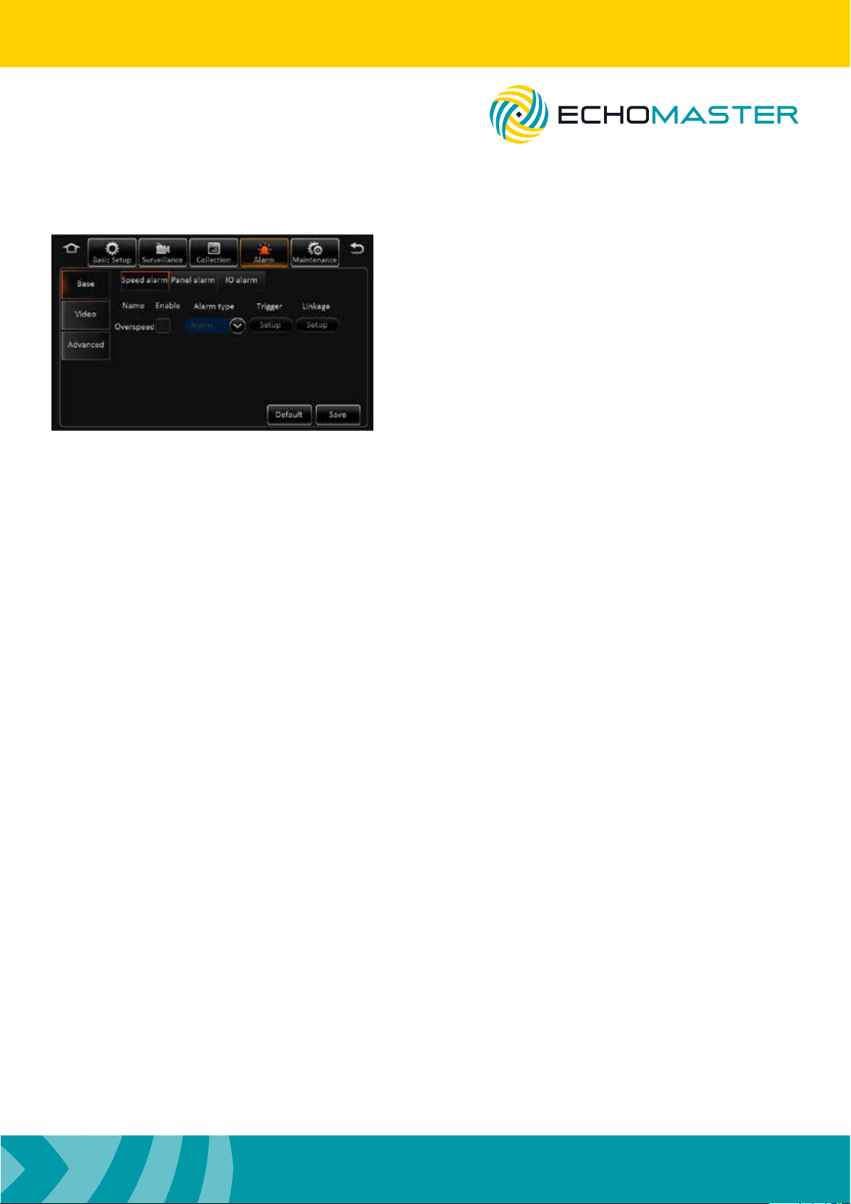
Speed Alarm
The speed alarm function can be turned on by ticking the
enable box. You can also then congure the type of alarm
reported (Alarm/Event).
Once enabled you can congure the speed setting,
speed difference and alarm duration by clicking the
trigger setup.
Using the linkage setup, it is also possible to link this alarm to one of the 2 available trigger outputs and
additionally congure post-recording times in addition to linking the alarm to a particular camera. The
alarm snap feature is not functional on this product.
Post recording will continue to record locked video for the set time after the alarm has been cancelled.
Panel Alarm
Requires additional devices.
IO Alarm
The speed alarm function can be turned on by ticking the enable box.
You can also then congure the type of alarm reported (Alarm or Event).
Once enabled, you can congure the trigger setup to high or low voltage by clicking the trigger setup.
Selecting high will mean that the trigger input on the chosen channel will need to go high (+12V) to trigger
the alarm; Setting this to low will mean that the trigger needs to be taken to ground to trigger the alarm.
Using the linkage setup, it is also possible to link this alarm to one of the 2 available trigger outputs and
additionally congure post-recording times in addition to linking the alarm to a particular camera. The
alarm snap feature is not functional on this product.
Post recording will continue to record locked video for the set time after the alarm has been cancelled.
It is possible to copy the settings from 1 alarm to any or all of the others using the copy feature.
19
Page 20

Installation Guide
DVR-50 (G)
5 Channel DVR Recorder
Video
Video loss
This enables a video loss on a particular channel or multiple channels to trigger an alarm and also to
switch display or le lock to a different channel.
Using the linkage setup, it is also possible to link this alarm to one of the 2 available trigger outputs and
additionally congure post-recording times in addition to linking the alarm to a particular camera.
The alarm snap feature is not functional on this product.
Post recording will continue to record locked video for the set time after the alarm has been cancelled.
Motion
This enables motion to be detected by the camera and trigger an alarm and switch to a chosen channel
display and lock le.
To set the motion detect area, enable the function and then click on trigger setup. Green highlighted areas
are detection areas whereas grey highlighted areas are not detected.
You are able to select the sensitivity and the detection area individually for each camera. Use the left
mouse button to drag the desired detection area on screen. If you make an error, you can clear all or part
of the detection area by click and dragging the mouse across any of the grey highlighted grid.
To back out of this menu, use the right mouse click.
Once happy with all the detection areas, click OK and Save on the main screen.
Using the linkage setup, it is also possible to link this alarm to one of the 2 available trigger outputs and
additionally congure post-recording times in addition to linking the alarm to a particular camera.
The alarm snap feature is not functional on this product.
Post recording will continue to record locked video for the set time after the alarm has been cancelled.
Cover
This enables the DVR to detect if a camera has been covered and switch the display to a chosen channel
and also to trigger an alarm and lock a recording.
Check the box to enable this feature and choose whether it reports as an event or an alarm.
By clicking the trigger setup, you can select which channels to enable this feature on and also set the
sensitivity, alarm duration and delay time before the alarm is triggered.
Using the linkage setup, it is also possible to link this alarm to one of the 2 available trigger outputs and
additionally congure post-recording times in addition to linking the alarm to a particular camera. The
alarm snap feature is not functional on this product.
Post recording will continue to record locked video for the set time after the alarm has been cancelled.
20
Page 21
DVR-50 (G)
5 Channel DVR Recorder
Advanced
Acc Alarm
Requires additional devices.
Electrifence
Requires additional devices.
Maintenance
Installation Guide
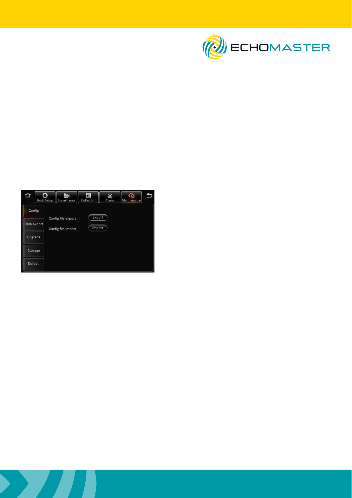
Cong
You are able to import and export conguration les which
is useful if you are tting multiple products to different
vehicles and wish to use the same conguration for all.
This will save having to congure each unit separately.
A USB hub can be used to simultaneously connect a USB
drive and a mouse so that this operation can be carried
out.
File Data
You can export any type of le data to an external USB device using this menu. Data can be exported in
bulk (all data) or only between a certain period of time.
A USB hub can be used to simultaneously connect a USB drive and a mouse so that this operation can be
carried out.
Upgrade
The unit can be upgraded from this menu option when upgrades are released. The upgrade le should be
placed on the root folder of a USB device.
A USB hub can be used to simultaneously connect a USB drive and a mouse so that this operation can be
carried out.
Storage
This option will display all connected storage mediums and also gives you the option to format each
device individually.
Reset
You are able to reset all parameters to default factory settings using the reset feature in this menu.
You can also reboot the system from this location.
21
Page 22
Installation Guide
5 Channel DVR Recorder
Video Playback
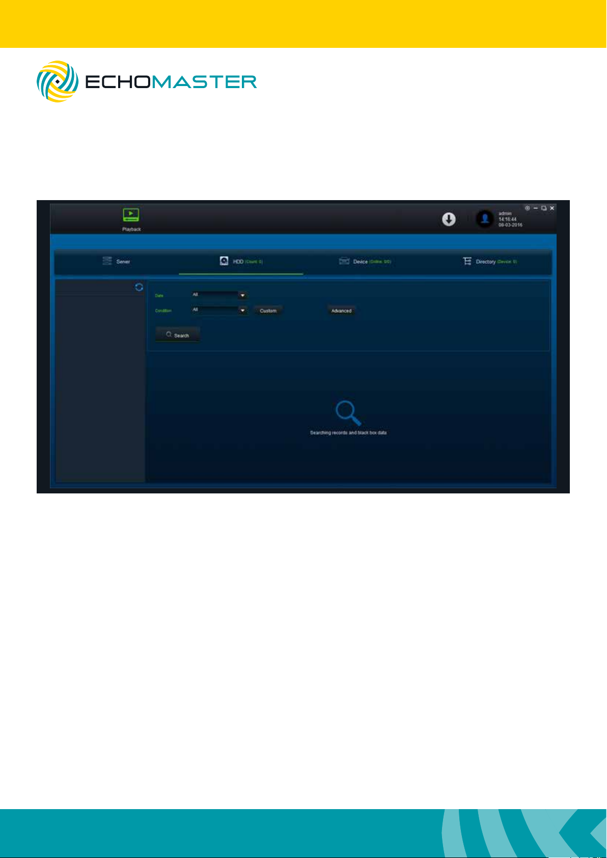
To playback stored video les you will need to download the Ceiba 2 software and user guide.
DVR-50 (G)
These can be downloaded from the following location.
http://echomaster.com/index.php?controller=attachment&id_attachment=660
22
Page 23
Installation Guide
DVR-50 (G)
5 Channel DVR Recorder
References
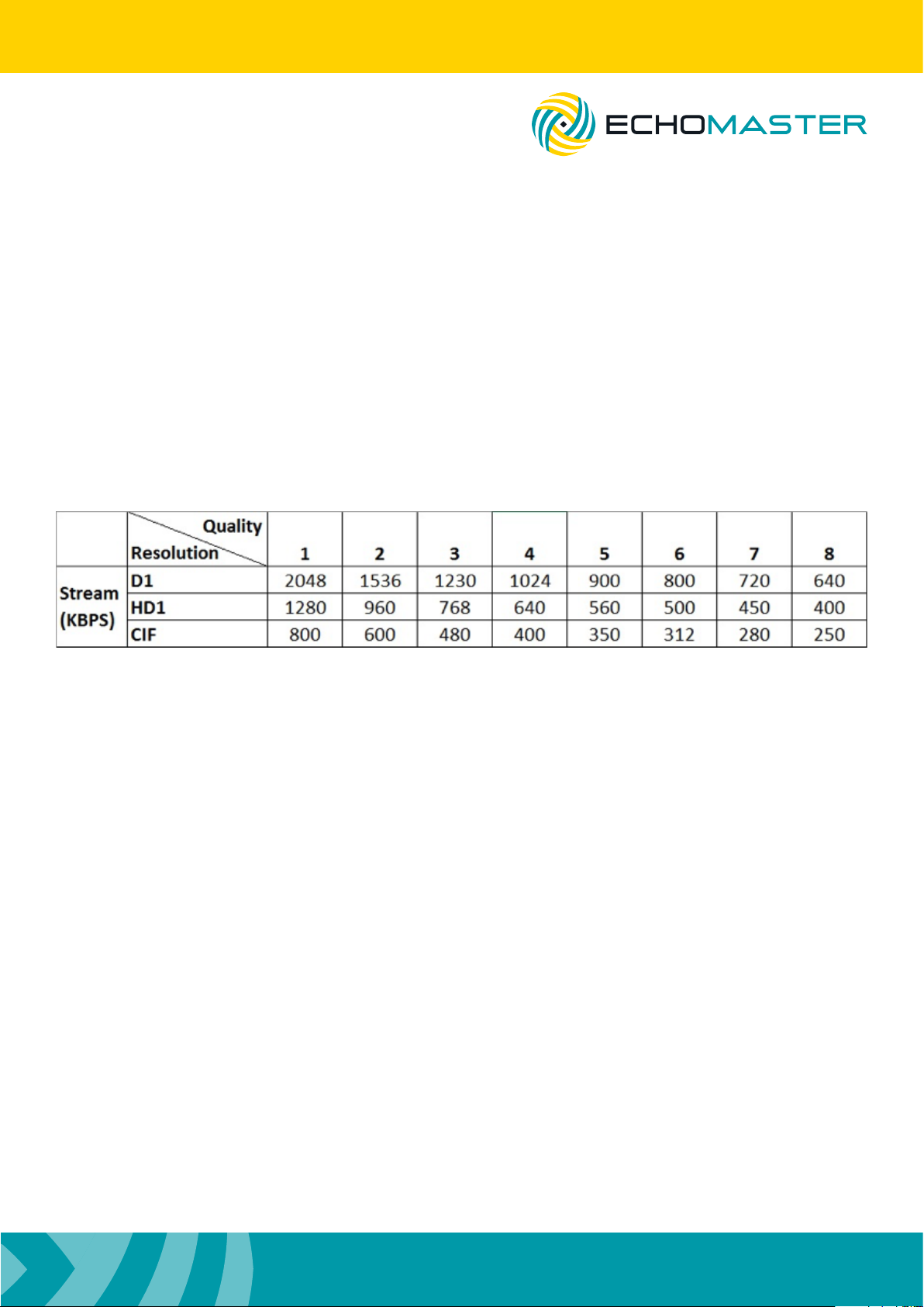
Storage Capacity
Recording File Size Calculation
The le size for each channel can be determined using the table above and the following calculation.
Recording Time (seconds) x Stream (Kbps) / 8 / 1024 = File size (Mb)
For example; 1 channel using D1 resolution at quality 2, recording for 1 hour.
3600 x 1536 / 8 / 1024 = 675Mb
23
Page 24

15500 Lightwave Drive, Suite 202, Clearwater, Florida 33760
Woolmer Way, Bordon, Hampshire, United Kingdom
email - [email protected] (US)
tel - 1-800-477-2267 (East Coast) - 1-888-883-2790 (West Coast)
email - [email protected] (Europe)
EchoMaster is a Power Brand of AAMP Global.
EchoMaster.com
 Loading...