

Page 1

1????
ENGLISH
FRANÇAIS
DEUTSCH
ITALIANO
ESPAÑOL
OPERATOR'S MANUAL
MANUEL D'UTILISATION
BEDIENUNGSANLEITUNG
MANUALE PER L'OPERATORE
MANUAL DE INSTRUCCIONES
RM-520ES
WARNING
READ THE INSTRUCTIONS CAREFULLY AND FOLLOW THE RULES FOR
SAFE OPERATION.
FAILURE TO DO SO COULD RESULT IN SERIOUS INJURY.
AVERTISSEMENT
LIRE ATTENTIVEMENT LES INSTRUCTIONS ET SUIVRE LESRÈGLES DE
SECURITÉ.LE NON-RESPECT DES RÈGLES DE SÉCURITÉ ENTRAÎNE UN
ISQUE DE BLESSURE GRAVE.
WARNUNG
LESEN SIE DIE BEDIENUNGSANLEITUNG SORGFÄLTIG DURCH, UND BE
FOLGEN SIE DIE SICHERHEITSREGELN. ANDERNFALLS BESTEHT DAS
RISIKO SCHWERER VERLETZUNGEN.
AVVERTENZA
LEGGERE E SEGUIRE ATTENTAMENTE LE ISTRUZIONI PER LAVORARE IN
CONDIZIONI DI MASSIMA SICUREZZA. LA MANCATA OSSERVANZA DELLE
ISTRUZIONI POTREBBE PROVOCARE LESIONI GRAVI.
ADVERTENCIA
LEA ATENTAMENTE LAS INSTRUCCIONES Y SIGA LAS INDICACIONES
PARA UN FUNCIONAMIENTO SEGURO. DE NO HACERLO, PODRÍA SUFRIR
LESIONES GRAVES.
Page 2

2
Page 3

1Cover
ENGLISH
(Original instructions)
OPERATOR'S MANUAL
GRASS-TRIMMER/BRUSHCUTTER
RM-520ES
WARNING
READ THE INSTRUCTIONS CAREFULLY AND FOLLOW THE
RULES FOR SAFE OPERATION.
FAILURE TO DO SO COULD RESULT IN SERIOUS INJURY.
Page 4

Contents
For safe use of your product...................................... ... .... ... ... ............................................3
Description..........................................................................................................................8
Before you start ..................................................................................................................9
Packing list ....................................................................................................................9
Assembly.....................................................................................................................10
Preparing the fuel ........................................................................................................12
Engine operation...............................................................................................................13
Starting the engine ......................................................................................................13
Stopping the engine..................................................................................................... 14
Trimming operation.......................................... .... ... ... ... .... ... ... ... .... ... ... ... ... .... ... ... ... .... ... ... 15
Basic trimming operation with nylon line cutting head.................................................16
Basic trimming operation with metal blade..................................................................18
Maintenance and care......................................................................................................20
Servicing guidelines.....................................................................................................20
Maintenance and care................................................. ... ... ... .... ... ... ... ... .... ... ... ... .... ......20
Storage........................................................................................................................28
Specifications....................................................................................................................29
Declaration of conformity..................................................................................................30
2
Page 5

For safe use of your product
For safe use of your product
Important information
WARNING
Please ensure that you read the operator's manual before using yo ur product.
About your operator's manual
This manual contains necessary information about the assembly, operation, and maintenance of your product.
Please read it carefully and absorb its contents.
Always keep your manual in a place where it is readily accessible.
If you have lost your manual or it is damaged and no longer readable, please purchase a new one from your dealer.
The units used in this manual are SI units (International System of Units). Figures in parentheses are reference values, and there may be a slight conversion error in some cases.
Failure to do so could lead to an accident or serious injury.
Intended use of this product
This product is lightweight, high-performance, petrol engined unit designed for weed control, grass trimming and
brush cutting in areas difficult to control by any other means.
Do not use this unit for any purpose other than aforementioned.
The content of this manual may be changed without notice for the purpose of upgrades to the product. Some of the
illustrations used may differ from the product itself in order to make the explanations clearer.
Please consult your dealer if anything is unclear or of concern.
Failure to do so could lead to an accident or serious injury.
Do not modify the product
You must not modify the product.
To do so could lead to an accident or serious injury. Any malfunction resulting from a modification to the product will not be
covered by the manufacturer's warranty.
Do not use the product unless it has been checked and maintained
You must not use the product unless it has been checked and maintained. Always ensure that the product is checked
and maintained on a regular basis.
Failure to do so could lead to an accident or serious injury.
Loaning or assigning your product
When loaning your product to another party, ensure that the person borrowing the product receives the operator's
manual along with it.
If you assign your product to another party, please enclose the operator's manual with the product when handing it
over.
Failure to do so could lead to an accident or serious injury.
Users of the product
The product should not be used by:
people who are tired
people who have taken alcohol
people who are on medication
people who are pregnant
people who are in poor physical condition
people who have not read the operator's manua l
children
Keep in mind that the operator or user is responsible for accidents or hazards occurring to other people or their property.
Failure to observe these instructions could lead to an accident.
The ignition system of this product generates electromagnetic fields during operation. Magnetic fields can cause
pacemaker interference or pacemaker failure. To reduce health risks, we recommend that pacemaker users consult
their physician and the pacemaker manufacturer before operating this product.
3
Page 6
For safe use of your product
WARNING
Vibration and cold
It is believed that a condition called Raynaud's Phenomenon which affects the fingers of certain individuals may be
brought about by exposure to vibration and cold. Exposure to vibration and cold may cause tingling and burn ing,
followed by loss of colour and numbness in the fingers. The following precautions are strongly recom mended because the minimum exposure which might trigge r the ai lment is unknown.
Keep your body warm, especially the head and neck, feet and ankles, and hands and wrists.
Maintain good blood circulation by performin g vigoro us arm exercises during frequent work breaks, and also by
not smoking.
Limit the number of hours of operation. Try to fill each day with jobs where operating the trimmer or other hand-
held power equipment is not required.
If you experience discomfort redness and swelling of the fingers, followed by whitening and loss of feeling, con-
sult your physician before exposing you rself further to cold and vibration.
Failure to observe these instructions could result in damage to your health.
Repetitive stress injuries
It is believed that over-using the muscles and tendons of the fingers, hands, arms and shoulders may cause soreness, swelling, numbness, weakness and extreme pain to the areas just mentioned. Certain repetitive hand activities
may put you at a high risk for developing a repetitive stress injury (RSI). To reduce the risk of RSI, do the following:
Avoid using your wrist in a bent, extended or twisted position.
Take periodic breaks to minimize repetition and rest your hands. Reduce the speed and force in which you do the
repetitive movement.
Do exercises to strengthen hand and arm muscles.
See a doctor if you feel tingling, numbness or pain in your fingers, hands, wrists or arms. The sooner RSI is diag-
nosed, the more likely permanent nerve and muscle damage can be prevented.
Failure to observe these instructions could result in damage to your health.
Proper training
Do not permit operation without proper training and protective equipment.
Be thoroughly familiar with the controls and proper use of unit.
Know how to stop the unit and shut off the engine.
Know how to unhook a harnessed unit quickly.
Never allow anyone to use the unit without proper instruction.
Failure to observe these instructions could result in damage to your health.
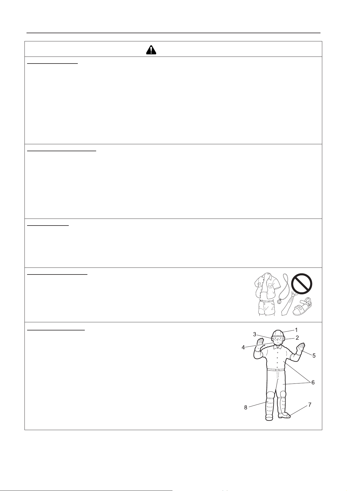
Wear proper clothing.
Secure hair so it is above shoulder length.
Do not wear ties, jewellery, or loose, dangling clothing which could be caught in the
unit.
Do not wear open toed footwear, or go bare-foot or barelegged.
Failure to observe these precautions could result in damage to your sight or hearing, or lead
to a serious injury.
Wear protective gear
Always wear the following protective gear when working with the trimmer.
1. Head protection (helmet): Protects the head
2. Ear muffs or ear plugs: Protect the hearing
3. Safety goggles: Protect the eyes
4. Face shield: Protects the face
5. Safety gloves: Protect the hands from cold and vibration
6. Work clothes that fit (long sleeves, long trousers): Protect the body
7. Heavy duty, non-slip protective boots (with toecaps) or non-slip work shoes
(with toecaps): Protect the feet
8. Shin guards: Protect the legs
Failure to observe these precautions could result in damage to your sight or hearing, or
lead to a serious injury.
When necessary, please use the protective gear below.
Dust mask: Protects the breathing apparatus
Bee net: To deal with attacks by bees
4
Page 7
For safe use of your product
WARNING
Environment of use and operation
Do not use the product:
under poor weather conditions.
on steep slopes or in places which give no secure foothold and are thus slippery.
at night or in dark places with poor visibility.
When using the product on a gentle slope, work in a level, contour-like motion.
A serious injury could result if you fall or slip, or fail to operate the product correctly.
For your own health and your safe and comfortable work, operate the machine within the air temperature range of
í5oC to 40oC.
Failure to observe these instructions could result in damage to your health.
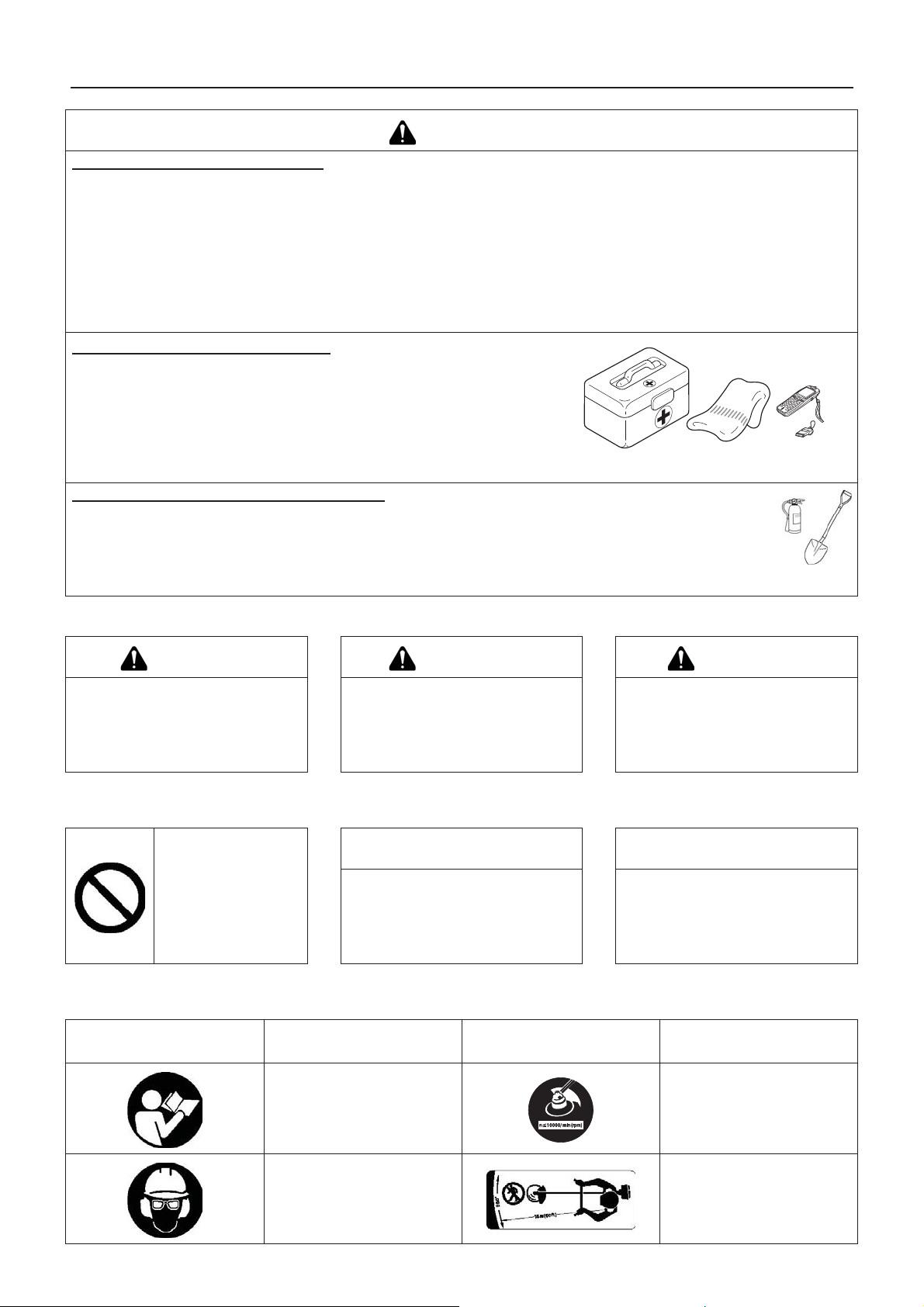
Being prepared in case of an injury
In the unlikely event of an accident or injury, please ensure that you are
prepared.
First aid kit
Towels and wipes (to stop any bleeding)
Whistle or mobile phone (for calling outside help)
If you are unable to perform first aid or call for outside help, the injury could
worsen.
Put safety first in the case of fire or smoke
If fire comes from the engine or smoke appears from any area other than the exhaust vent, first distance
yourself from the product to ensure your physical safety.
Use a shovel to throw sand or other such material on the fire to prevent it from spreading, or put it out
with a fire extinguisher.
A panicked reaction could result in the fire and other damage becoming more extensive.
Warning notices
DANGER WARNING CAUTION
This symbol accompanied by the
word "DANGER" calls attentions to
an act or a condition which will lead to
serious personal injury or death of operators and bystanders.
Other indicators
Circle and slash symbol means whatever is
shown is prohibited.
Symbols
Symbol form/shape Symbol description/applica-
This symbol accompanied by the
word "WARNING" calls attentions to
an act or a condition which can lead to
serious personal injury or death of operators and bystanders.
This enclosed message provides tips
for use, care and maintenance of the
product.
tion
"CAUTION" indicates a potentially
hazardous situation which, if not
avoided, may result in minor or moderate injury.
NOTE IMPORTANT
Framed text featuring the word "IMPORTANT" contains important infor-
mation about the use, checking,
maintenance and storage of the product described in this manual.
Symbol form/shape Symbol description/applica-
tion
Carefully read the operator's
manual
Wear eyes, ears and head
protection
The maximum speed of the
cutting attachment shaft in
r/min
Keep bystanders away 15 m
5
Page 8

For safe use of your product
Symbol form/shape Symbol description/applica-
tion
Wear foot protection and
gloves
Emergency stop
Warning!
Thrown objects!
Warning, side thrust
Usage without shield not permitted
Symbol form/shape Symbol description/applica-
tion
Petrol and oil mixture
Choke Control "Cold Start"
Position (Choke Closed)
Choke Control "Run" Position
(Choke Open)
Carburettor adjustment
- Idle speed
Lubricate in every 18 hours
Usage of metal blades not
permitted
Usage of nylon line cutting
head not permitted
Do not use the product in places with poor ventilation
Beware of fire Engine start
Beware of electric shocks
-
Loop handle
Beware of high-temperature
areas
Guaranteed sound power level
6
Page 9
For safe use of your product
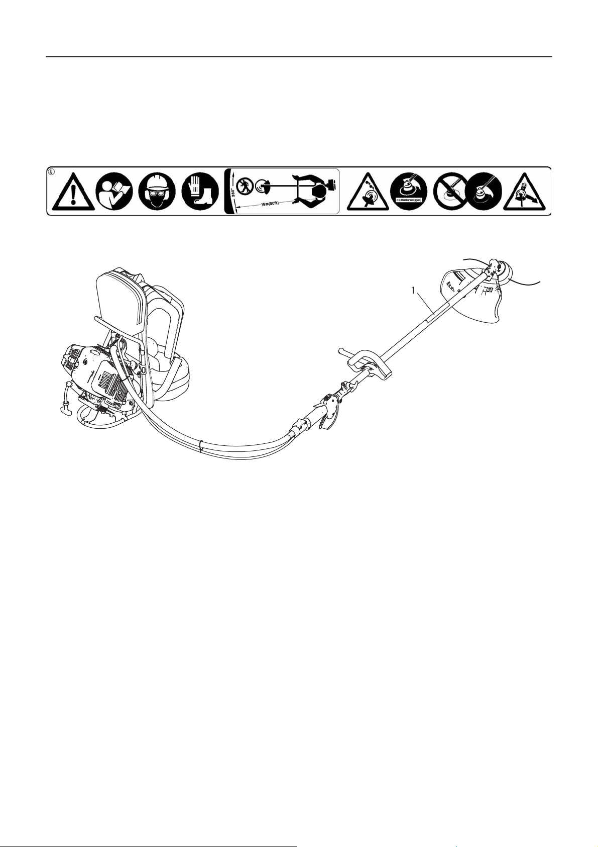
Safety decal(s)
The safety decal shown below has been attached to the products described in this manual. Ensure that you understand what
the decal means before using your product.
If the decal becomes unreadable due to wear and tear or damage, or peels off and is lost, please purchase a replacement decal
from your dealer and attach it in the location shown in the illustrations below. Ensure that the decal is readable at all times.
1. Safety decal (Part number 890617-43130)
7
Page 10
Description
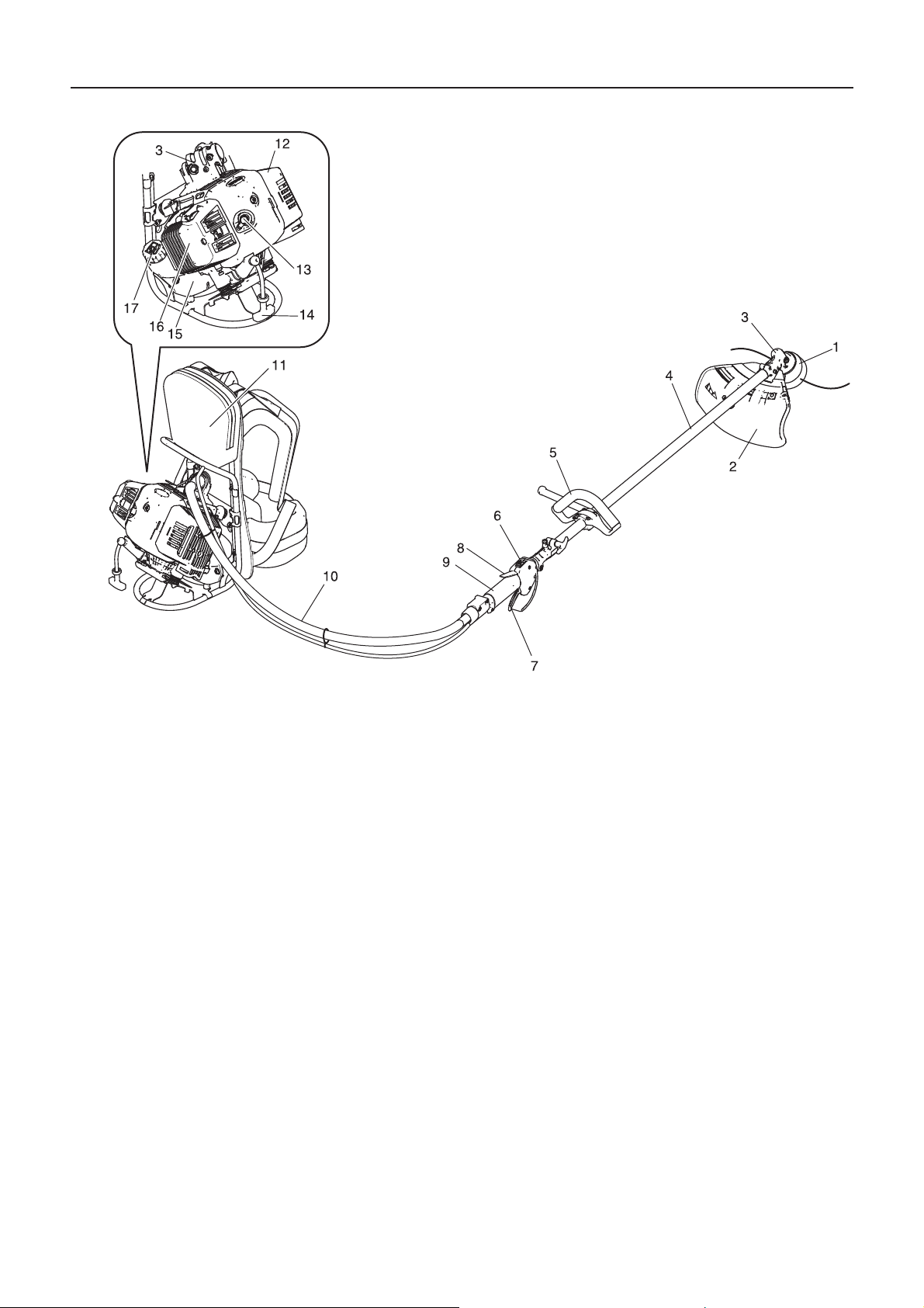
Description
1. Cutting attachment - Nylon line cutting head for cutting
grass and weed.
2. Shield - Device to protect the operator from accidental
contact with the cutting head and thrown objects.
3. Angle transmission - Having two gears to change to
angle of rotating axis.
4. Shaft tube - Part of the unit that provides a casing for
power transmission shaft.
5. Front handle - Handle located towards the cutting device.
6. Ignition switch - "Slide switch" mounted on top of the
throttle trigger housing, move switch upward to RUN,
downward to STOP position.
7. Throttle trigger - Activated by the operator's finger for
controlling the engine speed.
8. Throttle trigger lockout - Locks throttle trigger in the
idling position until you have a proper grip with your right
hand around the handle.
9. Rear handle - Handle located towards the knapsack
power unit.
10. Flexible shaft assembly - Flexible tube for the power
transmission shaft.
11. Tool bag - Removable bag for tool and accessories.
12. Silencer cover - Cover the silencer not to make operator touch to hot surface of silencer.
13. Spark plug
14. Starter handle - Pull handle to start the engine.
15. Fuel tank - Contains fuel and fuel filter.
16. Air cleaner cover - Covers air filter.
17. Fuel tank cap - For closing the fuel tank.
8
Page 11
Before you start
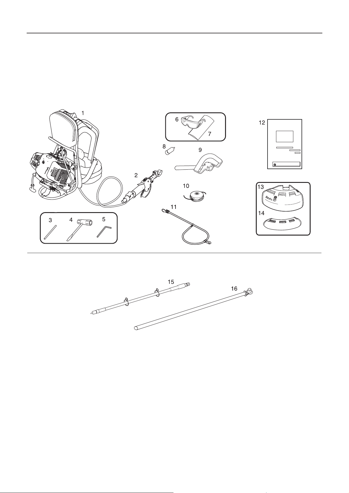
Packing list
The following parts are packed separately in the packing box.
When you have unpacked the box, please check the parts that it contains.
Contact your dealer if anything is missing or broken.
Engine
Before you start
Operation Shaft
1. Engine
2. Throttle trigger
3. Locking tool
4. Socket wrench
5. L-wrench
6. Safety goggles
7. Caution tag
8. Plastic cap
9. Front handle
10. Nylon line cutting head
11. Strap
12. Operator's manual
13. Shield (for nylon line cutting head)
14. Shield (for metal blade)
15. Flexible shaft assembly
16. Shaft tube
9
Page 12
Before you start
Assembly
WARNING
Read the operator's manual carefully to ensure that you assemble the product correctly.
Using a product that has been incorrectly assembled could lead to an accident or serious injury.
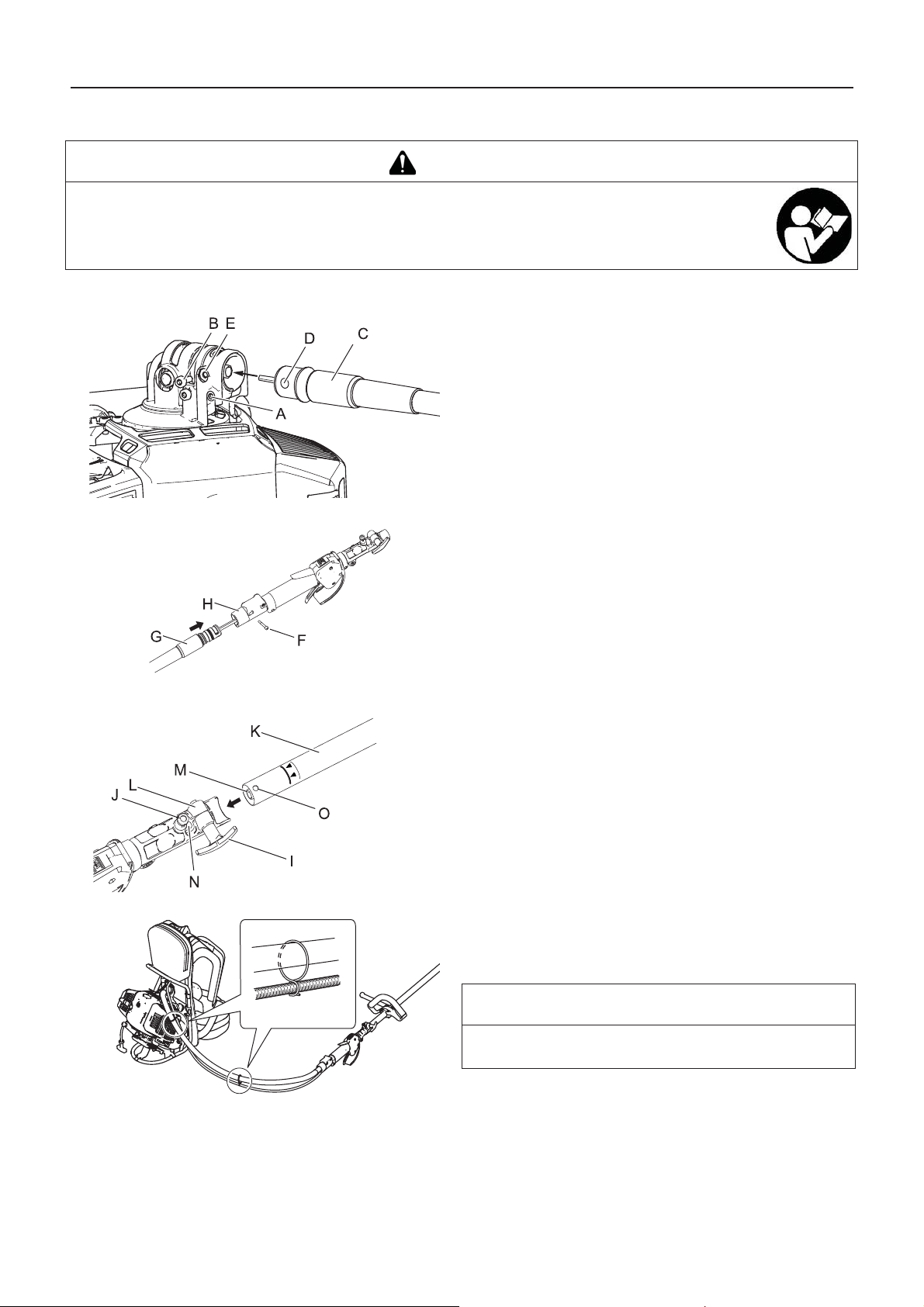
Operation shaft assembly
1. Loosen the bolt (A).
2. Remove the lock bolt (B).
3. Insert the flexible shaft assembly (C) into the angle transmission.
4. Align the hole of the flexible shaft assembly (D) with the hole
of the angle transmission (E).
5. Tighten the lock bolt and bolt.
6. Remove the lock bolt (F).
7. Insert the flexible shaft assembly (G) into the trigger tube.
8. Tighten the lock bolt.
9. Loosen the clamping knob (I).
10. Pull locator pin (J) out, and turn anticlockwise 1/4 turn to
lockout position.
11. Insert the operation shaft assembly (K) into the coupler (L)
as aligning the socket (M) with the flexible shaft (N).
12. Rotate locator pin 1/4 turn clockwise to engage operation
shaft hole. Insure locator pin is fully engaged by twisting operation shaft. Locator pin should snap flush in coupler. Full
engagement will prevent further shaft rotation.
13. Tighten the lock bolt.
14. The two pieces of clip attached to flexible shaft assembly
must be set to appropriate positions on the throttle cable (at
equal distance on the whole length of the flexible shaft assembly).
NOTE
To disassemble, reverse assembly instructions. Insert the
plastic cap to the coupler in order to prevent grease leakage
10
Page 13
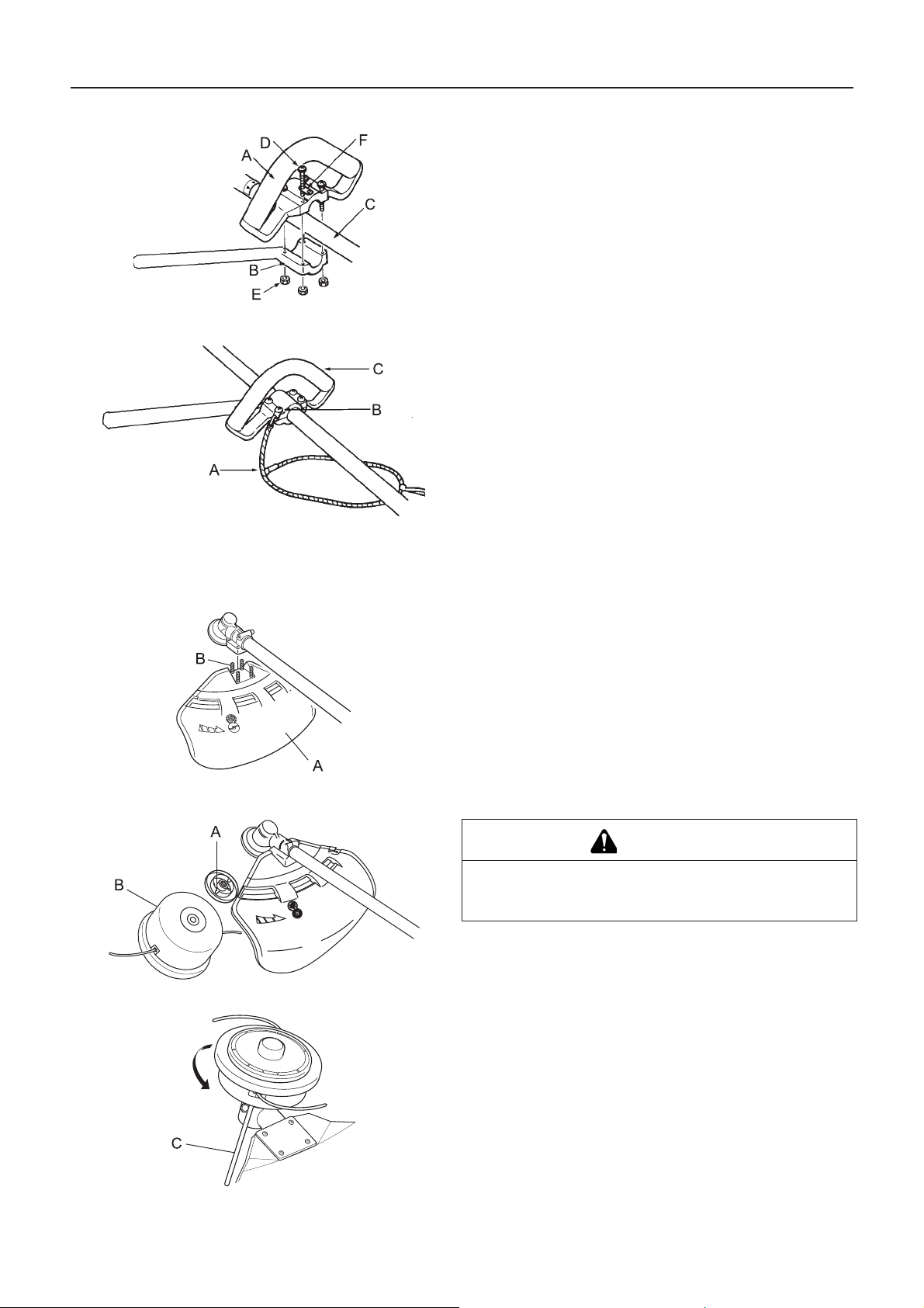
Loop handle assembly
Shoulder harness
Before you start
1. Assemble the front handle (A) and bracket (B) on the shaft
tube (C) loosely.
2. Adjust the location of the front handle to a convenient position.
3. Tighten the screws (M5×35) (D) and nuts (E) securely. - One
of the 4 screws must be tighten together with the hanger (F)
as illustrated.
1. Suit the length of knapsack band to comfort.
2. As the strap is elastic and adjustable, it is preferable to connect the strap (A) to the hangers (B) located on the front handle (C) and the left or right knapsack band to maintain a
fatigueless and comfortable operation.
1. Front handle
2. Hanger
3. Strap
Installation of shield
Installing nylon line cutting head
1. Fit shield (A) to mounting portion of angle transmission and
tighten 4 bolts (B).
CAUTION
Fix output shaft securely using locking tool in order to
prevent it form rotating when nylon cutting head is
mounted.
1. Insert locking tool into a hole located on the right side of angle transmission while forcing retainer spring to the left side.
2. Insert locking tool further into blade retainer fixing slot (A) to
fix output shaft.
3. Thread nylon line cutting head (B) onto shaft (anticlockwise)
until it is tight.
4. Remove locking tool (C).
11
Page 14
Before you start
Preparing the fuel
DANGER
Do not fuel up while the engine is hot or in operation.
Do not smoke or hold a flame near when refuelling.
If you do so, the fuel could ignite and cause fire, leading to burns.
WARNING
Do not fill fuel tanks indoors. Always fill fuel tanks outdoors over bare ground. Do not refuel the product on the loading platform of a truck, or in other such places.
Fuel tanks/cans may be under pressure. Always loosen fuel caps slowly allowing pressure to equalize.
Otherwise, fuel may get spewed.
Mop up any fuel that overflows or spills out due to overfilling.
Fuel spills can cause fire and burns when ignited.
After refuelling, always check that there are no leaks or discharges of fuel from the fuel pipe, fuel system grommets,
or around the fuel tank cap. If you do find fuel leaks or discharges, stop using the product immediately and contact
your dealer to have it repaired.
Any fuel leaks could cause fire.
Keep the refuelling tank in a shaded area away from fire.
Use an approved fuel container.
IMPORTANT
Fuel is a mixture of regular grade petrol and an air-cooled 2-stroke engine oil of reputable brand name. Minimum 89 Octane
unleaded petrol is recommended. Do not use fuel containing methyl alcohol or more than 10 % of ethyl alcohol.
Stored fuel ages. Do not mix more fuel than you expect to use in thirty (30) days.
Fuel
Recommended mixture ratio; 50: 1 (2%) for ISO-L-EGD
Standard (ISO/CD 13738), JASO FC,FD grade and ECHO
Premium 50: 1 oil.
Do not mix directly in engine fuel tank.
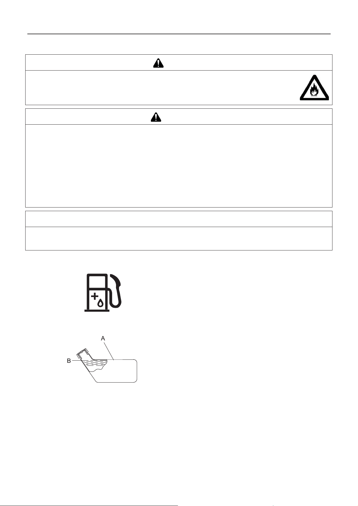
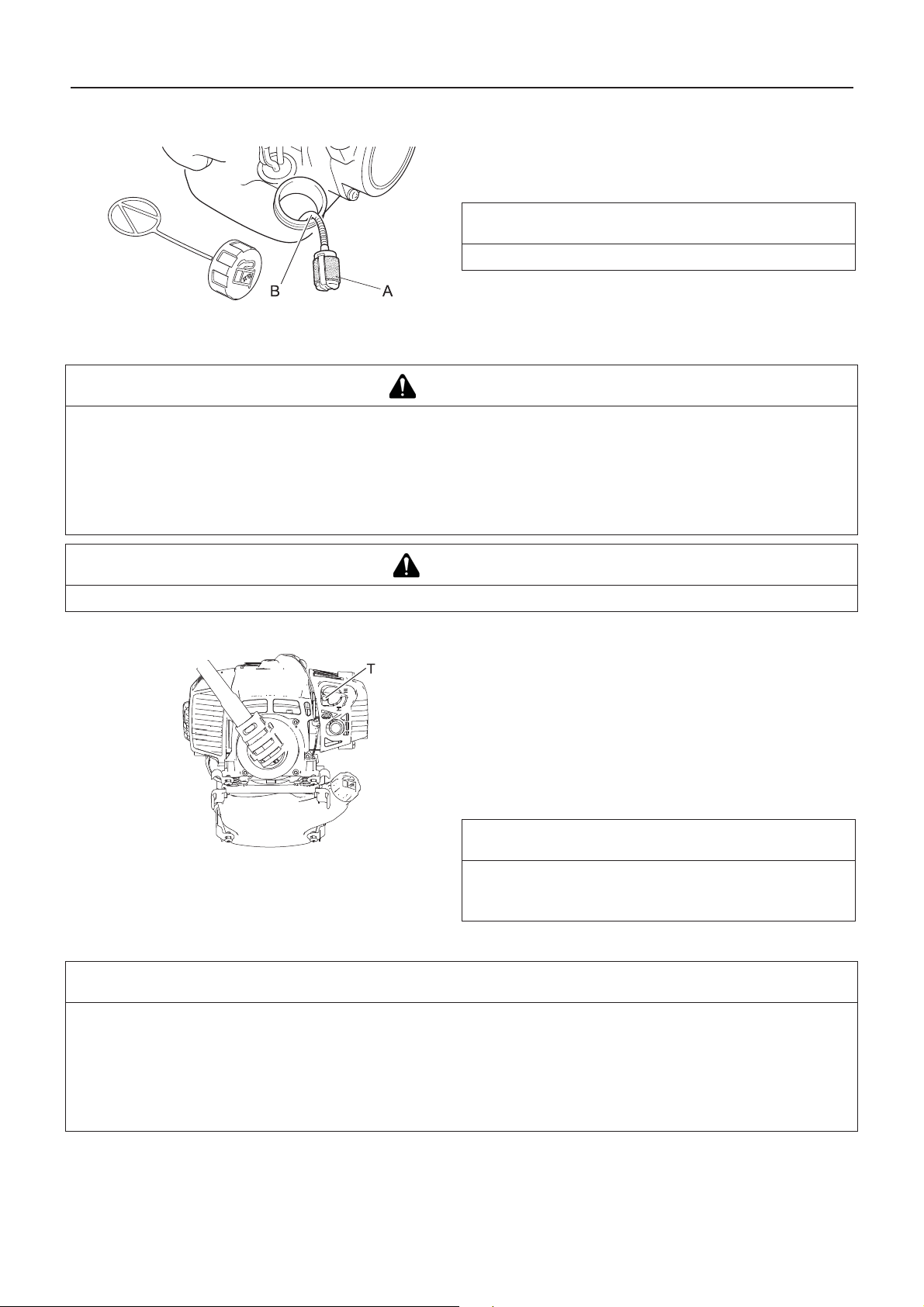
Fuel supply
Do not add so much fuel that it reaches the mouth of the fuel
tank (A). Keep the fuel within the prescribed level (up to the
shoulder level (B) of the fuel tank).
Tighten the fuel tank cap securely after refuelling.
12
Page 15

Engine operation
Engine operation
Starting the engine
WARNING
Be particularly careful to observe the following precautions when starting the engine:
Move at least 3m from the place where you refueled.
Place the product in a flat, well ventilated place.
Check that there are no fuel leaks.
Inspect metal blades for cracks.
Check that none of the nuts and bolts are loose.
Leave plenty of space around the product and do not allow people or animals near it.
Start the engine with the throttle trigger in the idle speed position.
Hold the product firmly to the ground when starting the engine.
Failure to observe the precautions could cause an accident or injury, or even lead to a fatality.
Check that there are no abnormal vibrations or sounds once the engine starts. Do not use the product if there are
abnormal vibrations or sounds. Contact your dealer to have it repaired.
Accidents involving parts that fall or shatter off can cause wounds or serious injury.
The exhaust fumes from the engine contain toxic gases. Do not operate the product indoors or in other
ill ventilated places.
The exhaust fumes could cause poisoning.
Do not touch silencer, spark plug, angle transmission, and other high temperature components while
the product is running or for some time after it stops.
You could burn yourself if you touch a high temperature component.
Do not touch spark plug, spark plug wire, and other high voltage components w hile the product is running.
You could receive an electric shock if you touch a high voltage component while the product is running.
If the cutting attachment rotates even though the throttle trigger is in the idle speed position when the engine is started, adjust the carburettor before using the product.
Failure to observe the precautions could cause an accident or injury, or even lead to a fatality.
NOTE
Pull out the starter grip gently at first, and then more rapidly. Do not pull the starter rope out to more than 2/3 of its length.
Do not let go of the starter grip as it returns.
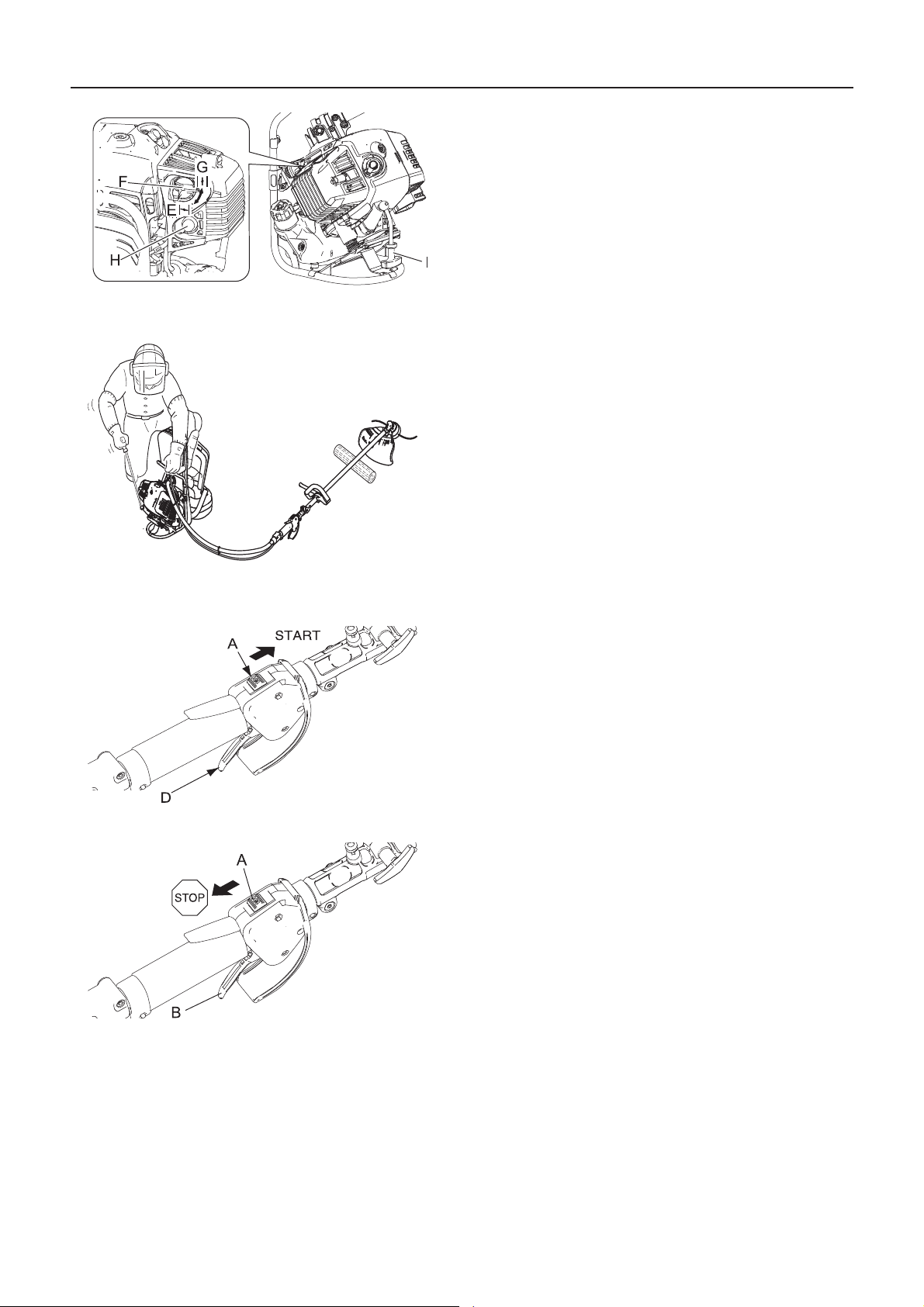
Starting a cold engine
(Connect the spark plug cap if the product has been in storage for
a long period of time.)
1. Remove the blade cover.
2. Placing the product on level ground, check to ensure that the
cutting attachment does not come into contact with the surface of the ground or any other impediment using a beam or
other such implement.
3. Move the ignition switch (A) to the Start position.
4. Make sure that the throttle trigger (D) is at the idle speed position.
13
Page 16
Engine operation
5. Move the choke lever (F) to the "Cold Start" (E) position.
6. Alternately press and release the purge bulb (H) until the fuel
is sucked up into it.
7. Checking that the area around you is safe, hold the position
closest to the engine firmly as shown in the illustration, pulling several times on the starter grip (I).
8. If you hear an explosion-like sound and the engine stops immediately, move the choke lever to the "Run" (G) position
and continue pulling on the starter grip to start the engine.
9. If the engine does not stop, return the choke lever gently to
the "Run" position.
10. Leave the engine to warm up at idle speed for a while.
Starting a warm engine
Stopping the engine
1. Move the ignition switch (A) to the Start position.
2. Make sure that the throttle trigger (D) is at the idle speed position.
3. Check that the choke lever is in the "Run" position.
4. If no fuel is visible in the purge bulb, alternately press and release the purge bulb until the fuel is sucked up into it.
5. Checking that the area around you is safe, hold the position
closest to the engine firmly, and pull on the starter grip to
start the engine.
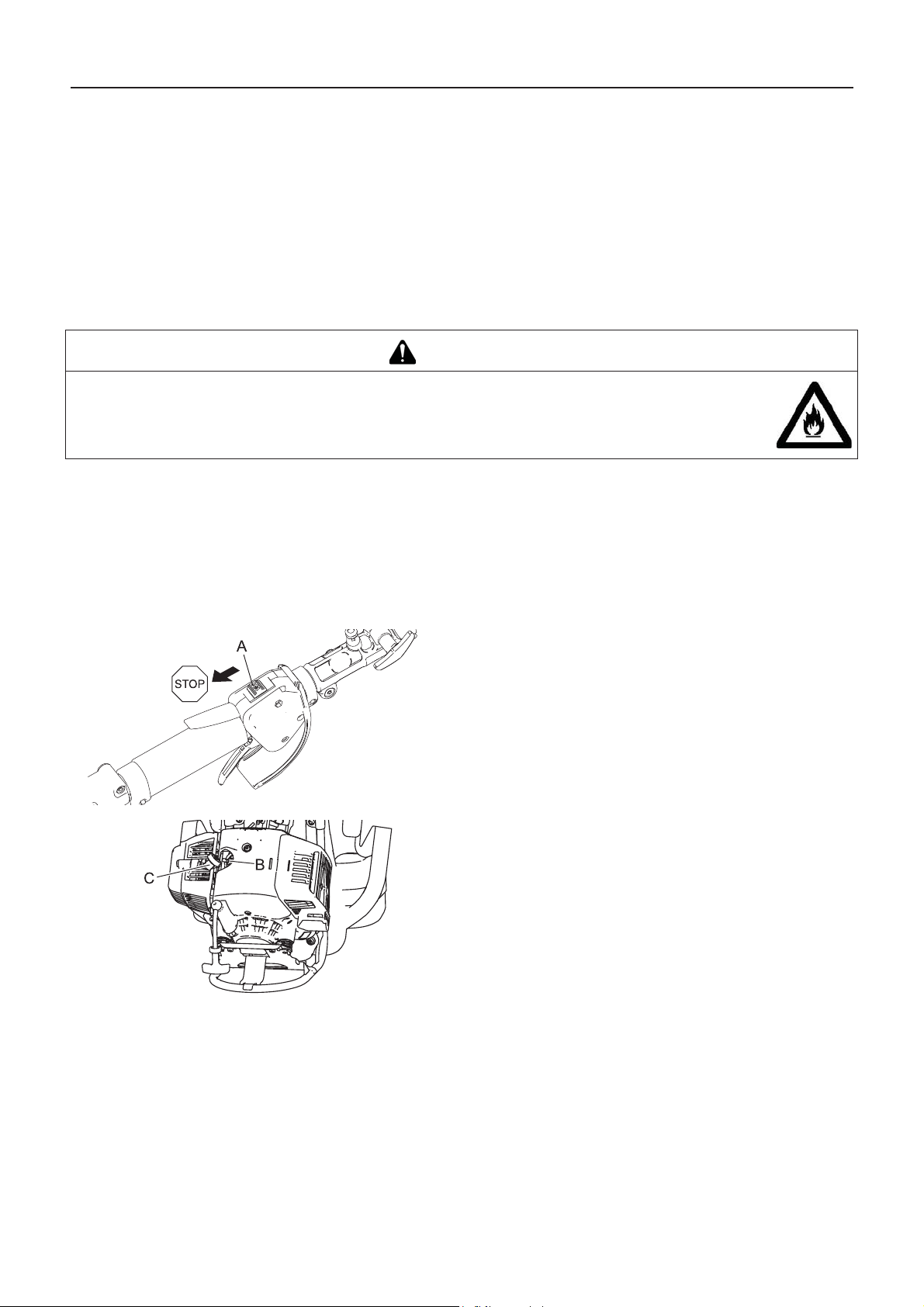
1. Move the throttle trigger (B) to the idle speed position and set
the engine to idling (i.e. low speed).
2. Move the ignition switch (A) to the Stop position.
3. In the event of an emergency, stop the engine immediately
using the ignition switch.
4. If the engine fails to stop, move the choke lever to the "Cold
Start" position. The engine will stall and come to a halt (an
emergency stop).
If the engine fails to stop when the ignition switch is used, have
the ignition switch checked and repaired by your dealer before
you use the product again.
5. Always disconnect the spark plug wire from the spark plug to
ensure the engine cannot be started before you work on the
unit or leave it unattended.
14
Page 17

Trimming operation
Trimming operation
DANGER
Always stop the engine when a cutting attachment jam occurs.
Severe injury can occur if a jam is removed and the cutting attachment suddenly starts.
Do not operate the product without the shield in place.
Any objects that ricochet off the cutting attachment could cause an accident or serious injury.
The area within a 15 m radius of the product is a danger zone. Be careful to observe the following precautions while working with the product.
Do not allow children and other people or pets to enter the danger
zone.
If another person enters the danger zone, turn off the engine to stop
the cutting attachment from rotating.
When approaching the operator, signal to him by, for example,
throwing twigs from outside the danger zone, and then check that
engine has been switched off and the cutting attachment has
stopped turning.
If more than one person is working with the product, identify the way
in which you will signal to each other and work at least 15 m apart.
Any objects that ricochet off the cutting attachment, and any contact with the cutting attachment, could cause blindness or a
fatal accident.
WARNING
Before starting work, check the area where you will be working and remove any small stones
and empty cans likely to ricochet off the cutting attachment, as well as any pieces of string
or wire that might become twisted around the cutting attachment.
An accident or serious injury can occur if foreign objects ricochet off the cutting attachment or wire
and other materials twisted round the product spring off it.
In the following situations, turn off the engine immediately and ensure that the cutting attachments have stopped
before checking each area of the product. Replace any damaged parts.
If the cutting attachment hits a rock, tree, post, or other such obstruction while you work.
If the product suddenly starts to vibrate abnormally.
Continuing to use parts when they are damaged could lead to an accident or serious injury.
Do not hold the cutting attachment up while you work. You must not work with the cutting attachments raised above
knee level.
Raising the cutting attachment above knee level brings the plane of rotation closer to the face, and any objects that fly off the
cutting attachments could cause an accident or serious injury.
Transport of the product
When transporting in the situations described below, turn off the engine and ensure that the trimmer blade has
stopped rotating, then fit the trimmer blade cover and position the silencer away from yourself.
Moving to the place where you are working.
Moving to another area while you are working.
Leaving the place where you have been working.
Failure to observe these precautions could cause burns or serious injury.
When transporting the product by car, empty the fuel tank, fit the blade cover, and secure the product firmly in place
to prevent it from moving around.
Travelling by car with fuel in the fuel tank could lead to a fire.
Never attempt to operate the product with one hand.
Ensure that you hook your thumbs around the grips, wrapping them in your
thumb and remaining fingers.
15
Page 18
Trimming operation
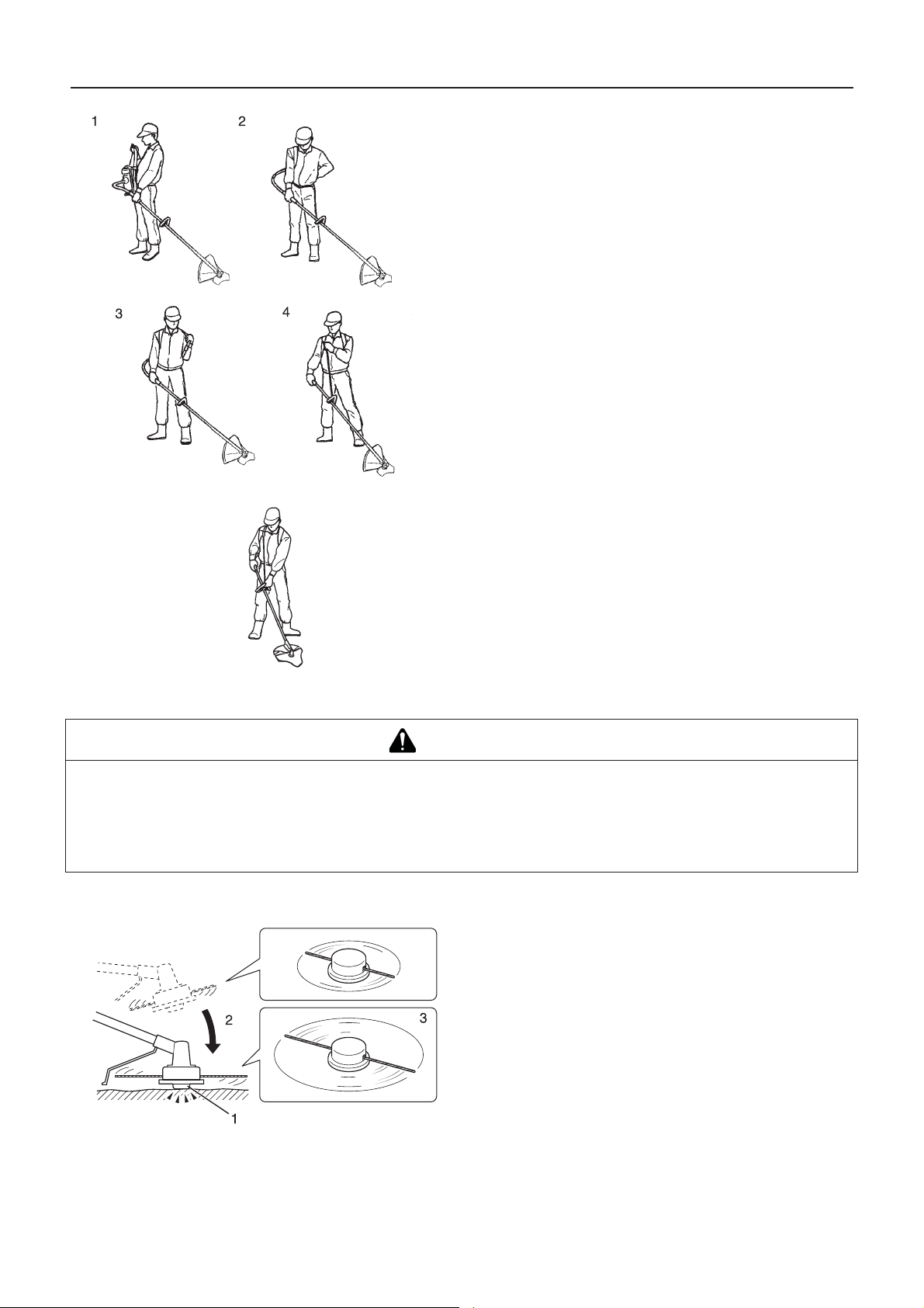
1. Hold the rear handle of shaft tube in left hand and hang the
right knapsack band on the right shoulder.
2. Hold the rear handle of shaft tube in right hand and hang the
left knapsack band on the left shoulder.
3. For even load on both sides of shoulder, joggle the unit on
the shoulder a couple of times.
4. It is preferable to connect the strap to the hangers located on
the loop handle the left or right knapsack band and adjust the
length of the strap to maintain a comfortable operation.
Increase engine speed as necessary, heavy weeds will require
more power than cutting grass.
Hold the front handle (loop handle) and rear handle both hands.
When cutting weeds or grass, swing the blade right and left in
an arc as you move forward.
The blade rotates anticlockwise, so it is necessary to cut the
object from the right to the left.
The manner of walking is as follows: - Place the right foot in
front of the left foot without fail. - Step the right foot forward
firstly and secure your footing. - And then follow the left foot to
the behind of the right foot.
Basic trimming operation with nylon line cutting head
WARNING
Serious injury may result from the improper use of cutti ng attachment. Read and comply with all safety instructions
listed in this manual.
Use only cutting attachments recommended by YAMABIKO CORPORATION.
Excessive nylon line beyond cut off knife could fly off when the nylon line cutting head starts rotating after adjustment of nylon line length.
Failure to do so could lead to an accident or serious injury.
Adjusting nylon line
Do not rotate the nylon line cutting head at more than 10000 r/
min.
When releasing nylon line from spool, hit tap knob of spool
against the ground surface lightly at rotation speed lower than
4500 r/min.
Cut off knife on the shield adjusts cutting swath automatically
by cutting nylon lines evenly when attachment starts rotating.
When operating with less than maximum cutting swath, cut
two nylon lines in equal lengths.
1. Tap knob
2. Hit knob against the ground surface lightly
3. Nylon line comes out
16
Page 19
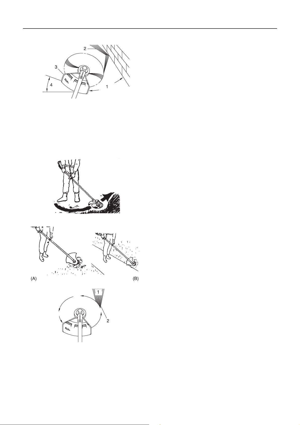
Trimming
Scything
Trimming operation
This is feeding the trimmer carefully into the material you wish
to cut. Tilt the head slightly to direct the debris away from you.
If cutting up to a barrier such as a fence, wall or tree, approach
from an angle where any debris ricocheting off the barrier will
fly away from you.
Move the nylon line cutting head slowly until the grass is cut
right up to the barrier, but do not jam (overfeed) the line into
the barrier. If trimming up wire mesh or chain link fencing, be
careful to feed only up to the wire. If you go too far, the line will
snap off around the wire.
Trimming can be done to cut through weed stems one at a
time. Place the nylon line cutting head near the bottom of the
weed never high up, which could cause the weed to chatter
and catch the line. Rather than cut the weed right through, just
use the very end of the line to wear through the stem slowly.
1. Angle to wall
2. Debris
3. Knife side raised
4. Angle to ground
This is the cutting or mowing of large grassy areas by sweep-
ing or swinging the trimmer in a level arc. Use a smooth, easy
motion. Do not try to hack or chop down the grass. Tilt the nylon line cutting head to direct the debris away from you on the
scything stroke. Then return without cutting grass for another
stroke. If you are well protected and do not care whether some
debris is thrown in your direction, you may scythe in both directions.
Scalping and edging
Both of these are done with the nylon line cutting head tilted at
a steep angle. Scalping (A) is removing top growth, leaving the
earth bare. Edging (B) is trimming the grass back where it has
spread over a pavement or driveway. During both edging and
scalping, hold the unit at a steep angle in a position where the
debris, and any dislodged dirt and stone, will not come back
towards you even if it ricochets off the hard surface.
Although the pictures show how to edge and scalp, every op-
erator must find for himself the angles which suit his body size
and cutting situation.
For nearly all cutting, it is good to tilt the nylon line cutting head
so that contact is made on the part of line circle where the line
is moving away from you and the shield (See appropriate picture). This results in the debris being thrown away from you.
Tilting the head to the wrong side will shoot the debris toward
you. If the nylon line cutting head is held flat to the ground so
that cutting occurs on the whole line circle, debris will be
thrown at you, drag will slow the engine, and you will use up a
lot of line.
Nylon line cutting head rotates anticlockwise. The knife will be
on the left side of the shield.
1. Debris
2. Cut on this side
17
Page 20
Trimming operation
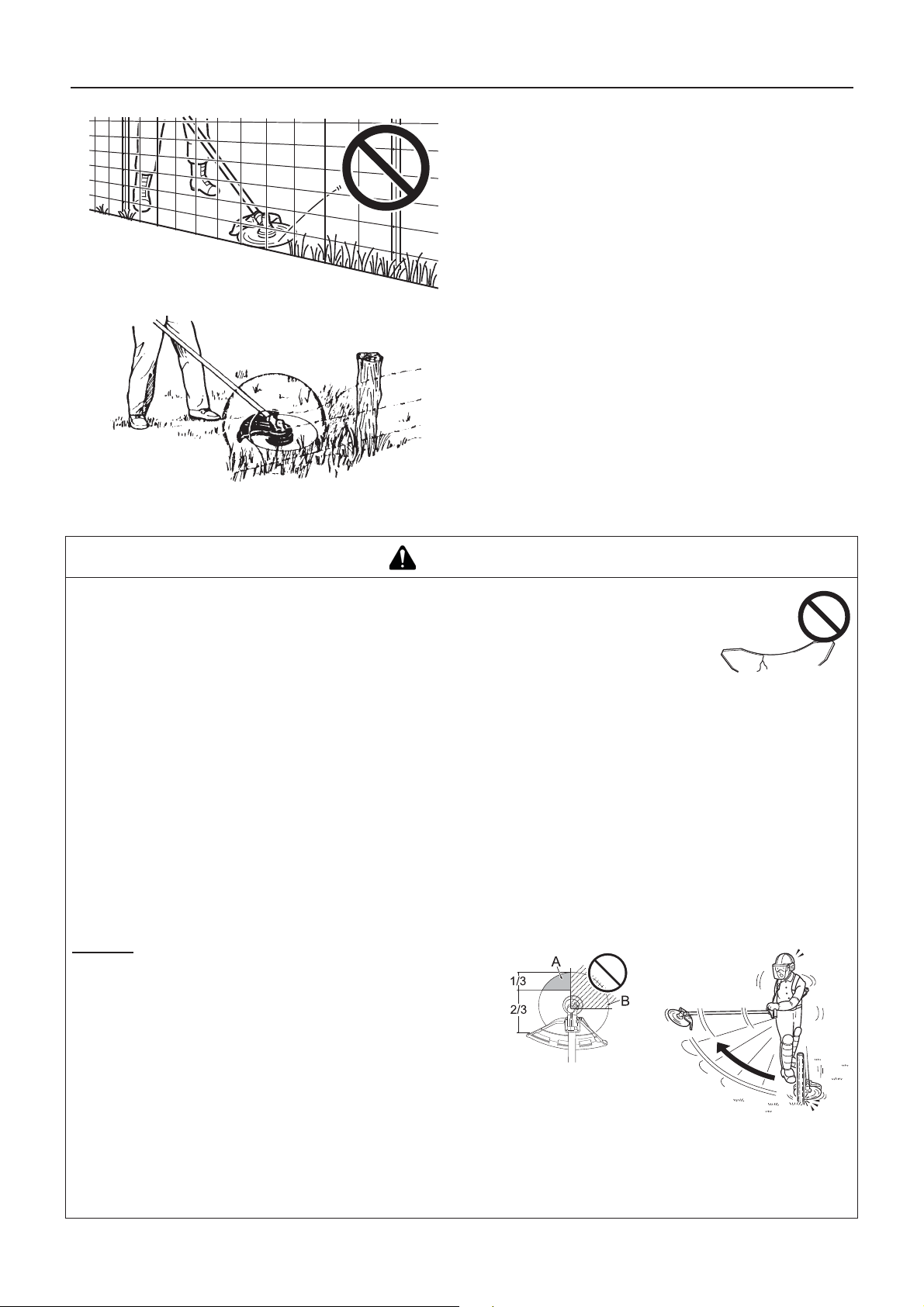
Basic trimming operation with metal blade
Do not push the line into tough weeds, trees, or wire fences.
Pushing the line into chicken wire, chain link fencing or thick
brush can result in snapped-off line ends being hurled back at
the operator. The proper way is to cut right up to a barrier, such
as any of those mentioned, but never run the line into or
through the obstruction. Do not cut closely to obstruction or
barrier.
Avoid nylon line contact with broken wire fencing. Pieces of
wire broken off by the trimmer can be hurled at high speeds.
WARNING
Please observe the following instructions when trimming.
Check to ensure that the trimmer blade has been tightened securely in place.
Replace the shield if it is damaged or cracked.
Replace the trimmer blade nut when it becomes worn.
Do not cut into the ground with the blade.
Do not operate with a dull, bent, fractured or discoloured blade and worn or damaged nut.
Do not run engine at full throttle without a load.
Failure to do so could lead to an accident or serious injury.
Use only cutting attachments recommended by YAMABIKO CORPORATION.
The type of blade used must be matched to the type and size of material cut. An improper or dull blade can cause
serious personal injury. Blades must be sharp. Dull blades increase the chance of kick-out and injury to yourself and
bystanders.
Plastic/Nylon Grass/Weed Blades may be used where ever the nylon line head is used. Do not use this blade for
heavy weeds or brush.
The 3 cutter blade is designed especially to cut weeds and grass. To avoid injury due to kickback or blade fracture,
do not use the 3 cutter blade to cut brush or trees.
8 Tooth Weed/Grass Blade is designed for grass, garden debris and thick weeds. Do not use this blade for brush
or heavy woody growth, 19 mm diameter or larger.
22 Tooth Clearing Blade is designed for dense thickets and saplings up to 64 mm diameter.
80 Tooth Brush Blade is designed for cutting brush and woody growth up to 13 mm diameter.
Damaged or shattered blades can cause accidents and serious injury.
Kickback
The phenomenon that occurs if the trimmer blade comes into
contact with a tree, post, rock or other hard object while rotating at high speed and reacts by recoiling powerfully and
instantaneously is known as kickback.
Causing kickback can result in a loss of control over the
product and is highly dangerous.
In particular, if the front-right quadrant of the trimmer blade
(B) strikes a shrub or other such object, the trimmer blade
will cause the product to recoil sharply backwards to the
right.
To prevent kickback, do not trim from left to right. Be careful to ensure that the trimmer blade does not strike any
hard objects.
When trimming, ensure that the object you are cutting meets the portion of the blade 1/3 in from the front edge on
the left-hand side (A).
Failure to do so could cause an injury or fatal accident.
18
Page 21

Scything weeds
Trimming operation
This is cutting by swinging the cutting attachment in a level
arc. It can quickly clear areas of field grass and weeds. Scything should not be used to cut large, tough weeds or woody
growths.
If a sapling or shrub binds the cutting attachment, do not use
the cutting attachment as a lever to free the bind, because this
will cause cutting attachment failure.
Instead, shut off the engine and push the sapling or shrub to
free the blades.
19
Page 22

Maintenance and care
Maintenance and care
WARNING
Observe the following precautions when checking and maintaining your product after use:
Turn the engine off and do not attempt to check or maintain the product until the engine has cooled.
You could burn yourself.
Remove the spark plug cap before performing checks and main tenance.
An accident could occur if the product starts unexpectedly.
IMPORTANT
Checking and maintenance requires specialist knowledge. If you are unable to check and maintain the product or deal with a
fault yourself, consult your dealer. Do not attempt to dismantle the product.
Servicing guidelines
Area Maintenance Page Before use Monthly
Air filter Clean/Replace 20 •
Fuel filter Inspect/Clean/Replace 21 •
Spark plug Inspect/Clean/Adjust/Replace 22 •
Carburettor Adjust/Replace and adjust 21 •
Cooling system Inspect/Clean 21 •
Silencer Inspect/Tighten 22 •
Silencer Clean 22 •***
Flexible shaft Grease 22 •*
Angle transmission Grease 23 •**
Starter Inspect - •
Cut off knife Inspect/Clean - •
Fuel system Inspect 21 •
Screws, bolts and nuts Inspect, Tighten/Replace - •
* Or 18 hours, whichever occurs first. ** Or 50 hours, whichever occurs first. *** Or 100 hours, whichever occurs first.
IMPORTANT
Time intervals are maximum. Actual use and your experience will determine the frequency of required maintenance.
Maintenance and care
If you have any questions or problems, please contact your dealer.
Cleaning air filter
1. Close choke. Loosen screw and remove air cleaner cover
(A).
2. Remove air filter (B) (air filter is located inside air cleaner
cover).
3. Brush dirt from filter or clean with compressed air.
4. Reinstall filter.
5. Reinstall cover and tighten screw.
20
Page 23
Maintenance and care
Replacing fuel filter
1. Use a piece of metal wire or the like to pick up fuel filter (A)
through fuel tank opening.
2. Pull old filter from fuel line (B).
3. Install new fuel filter.
NOTE
If filter is excessive dirty or no longer fits properly, replace it.
Carburettor adjustment
WARNING
YOU MAY ADJUST THE IDLE SPEED ONLY by turning the idle speed adjustment screw (T).
During carburettor adjustment, the cutting attachment may move. Pay utmost attention and care to the cutting attachment so as not to get injured by the moving cutter.
When carburettor adjustment is completed, the cutting attachment should not move at idle speed, otherwise serious
personal injury may result.
You must NOT carry out any Carburettor adjustment, other than the idle speed. All other adjustments MUST be performed by an authorized service dea ler, or serious personal injury may re sult due to malfunction of the engine.
CAUTION
When there is trouble with the carburettor, contact an authorized service dealer.
Every unit is test run at the factory and the carburettor is fine
tuned for maximum performance.
Before adjusting carburettor, clean or replace air filter, start engine and run several minutes to bring it to operating temperature.
To adjust the carburettor proceed as follow:
Turn "idle" speed adjustment screw (T) clockwise until cutting
attachment begins to turn, then turn screw(T) out anticlockwise until cutting attachment stops turning. Turn screw (T) out,
anticlockwise, and additional 1 turn.
NOTE
When the carburettor cannot be adjusted properly with the idle
speed adjustment screw (T), you must contact an authorized
service dealer.
Cooling system maintenance
IMPORTANT
To maintain proper engine operating temperature, cooling air must pass freely through the cylinder fin area. This
flow of air carries combustion heat away from the engine. Overheating and engine seizure can occur when:
Air intakes are blocked, preventing cooling air from reaching the cylinder,
Dust and grass build up on the outside of the cylinder. This build-up insulates the engine and prevents the heat
from leaving.
Removal of cooling passage blockages or cleaning of cylinder fins is considered "Normal Maintenance". Any resultant failure
attributed to lack of maintenance is not warranted.
21
Page 24

Maintenance and care
Air intake
Cleaning silencer
Keep dirt away from engine and air intake grid.
Carbon deposits in silencer (A) will cause a drop in engine out-
put and overheating. Clean deposits from silencer.
IMPORTANT
Do not remove the silencer cover. If necessary, Please consult
your dealer.
Check fuel system
Check spark plug
DPP
Lubricating flexible shaft
Check before every use.
After refuelling, make sure fuel does not leak or exude from
around fuel pipe (A), fuel grommet (B) or fuel tank cap (C).
In case of fuel leakage or exudation, there is a danger of fire.
Stop using the machine immediately and request your dealer
to inspect or replace.
1. Check plug gap. Correct gap is 0.6 mm to 0.7 mm.
2. Inspect electrode for wear.
3. Inspect insulator for oil or other deposits.
4. If the electrodes or terminals are worn, or if there are cracks
in the ceramics, replace them with new parts.
5. Tighten to 15 N·m - 17 N·m (150kgf·cm to 170 kgf·cm).
The spark test (for checking whether the spark plug is spark-
ing) must be carried out by your dealer.
All the surface of the flexible shaft should always be properly
greased.
At the time of delivery from the pl ant, this is greased, so evenly
grease all the surface of the flexible shaft approximately 10 mL
in every 18 hours.
1. Draw out the flexible shaft assembly from the angle transmission.
22
Page 25

Angle transmission
Maintenance and care
2. Draw out the flexible shaft from the flexible shaft assembly.
3. Use the same grease as the angle transmission's.
4. When reassemble, it is preferable to fit the flexible shaft reversely, and the stopper (A) must be fitted on the angle
transmission side of the flexible shaft.
1. Remove the plug (A) and drain screw (B) from the angle
transmission (C).
2. Add grease into the transmission until old grease is pushed
out. If necessary, use a low pressure pump.
3. Reinstall the drain screw and plug.
1. Remove the plug (A) from the angle transmission (C).
2. Add grease, if necessary, use a low pressure pump.
Method to change shield
Installing blade (option)
IMPORTANT
Use the genuine grease from YAMABIKO CORPORATION
(Part number: X695-000010).
3. Reinstall the plug.
There are two types of shields: namely the one used exclu-
sively for nylon line cutting head and the other one used exclusively for metal blade. When metal blade is used, use the
shield for metal blade.
1. Fully loosen the bolt (A) on the right side of the bracket (B)
to slide the shield. The bolt itself cannot be removed from the
bracket.
2. Pushing the button (C), slide the shield (D) to the left and remove it.
3. Put shield of other type (E) into groove and slide it to the right
until it stops. Be sure to tighten the bolt.
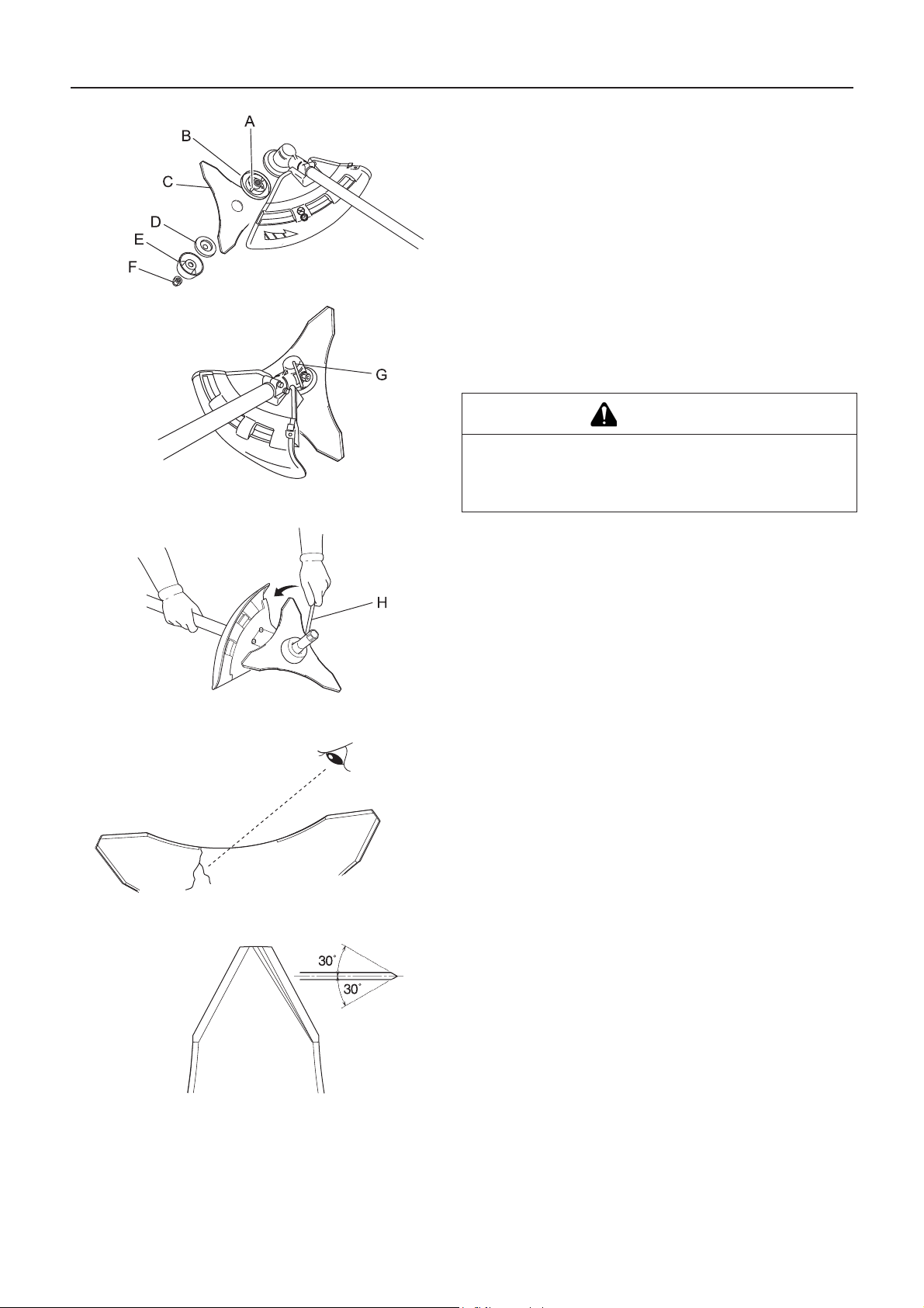
WARNING
Wear heavy duty gloves when working with the trimmer blade.
When replacing the trimmer blade during a trimming task, ensure that the engine is switched off and that the blades
have stopped.
When turning the product over to replace the trimmer blade, ensure that the fuel tank cap is securely in place.
Do not attempt to fit the trimmer blade with one hand or without using the socket spanner. Fit the trimmer blade accurately using the supplied socket spanner and tighten firmly in position.
Do not use any tools other than the provided socket spanner to tighten the blade; a pneumatic or electric tool may
tighten the blade more than necessary and cause the nut or the output shaft to break.
If worn nut and cup for blade are used, there is a danger of blade getting loose. Replace them with new one.
Failure to do so could lead to an injury or serious accident, or cause a fire.
23
Page 26
Maintenance and care
1. Inspect blades (C) before installation. Check for sharpness.
Dull blades increase the risk of blade kickback reactions.Small cracks can develop into fractures resulting in a
piece of blade flying off during operation. Discard cracked
blades no matter how small the crack.
2. Securely tighten the blade retainer (B), blade, lower blade
retainer (D), cup (E), and nut (F) by hand.
3. Insert locking tool (G) into a hole located on the right side of
angle transmission while forcing retainer spring to the left
side.
4. Insert locking tool further into blade retainer fixing slot (A) to
fix output shaft.
CAUTION
Fix output shaft securely using locking tool in order to
prevent it form rotating when blade is mounted. Otherwise, the blade fastening nut will not be tightened sufficiently.
Checking the blade
5. Tighten the nut (turn anticlockwise) using a socket wrench
(H). Never fasten while applying your weight. Otherwise the
thread of nut could be broken.
Use only blade designated for this model by the manufacturer.
When a crack is noticed on the blade, do not use it but replace
with a new one.
Ensure that the blade is correctly fitted in accordance with the
instructions.
When the cutting blade becomes dull due to wear reverse it for
further use.
When chip or bend occurs on the blade, vibration will increase.
Replace with new one.
When filing the blade file 3 cutting edges evenly using a flat file
as shown in the illustration. Otherwise, the balance will be lost
and vibration will increase.
24
Page 27

Checking the nylon line cutting head
Maintenance and care
1. Make sure each periphery of the 2 retaining pawls of housing
spreads almost fully up to the outer periphery of the respective cover window.
2. Check mount of cutting head on trimmer and tighten if it is
loose.
3. Check the cutter head for deflection or abnormal noise rotating it by hand. Deflection or abnormal noise can cause abnormal vibration to occur or mount to trimmer to loosen
during rotation which is dangerous.
4. Inspect cover and tap knob for wear. When slot appears on
bottom of the tap knob or when slot appears on cover bottom
close to outlet for nylon line, replace them with new parts
without fail.
5. Check the cutting head for crack or chip. Replace parts that
show any crack or chip with new ones without fail.
Replacing nylon line
DANGER
Shut down trimmer engine without fail and make sure nylon line cutting head has stopped rotating before starting
replacement procedure.
To do so could lead to an accident or serious injury.
WARNING
Use only flexible, non-metallic line recommended by YAMABIKO CORPORATION.
Failure to do so could lead to an accident or serious injury.
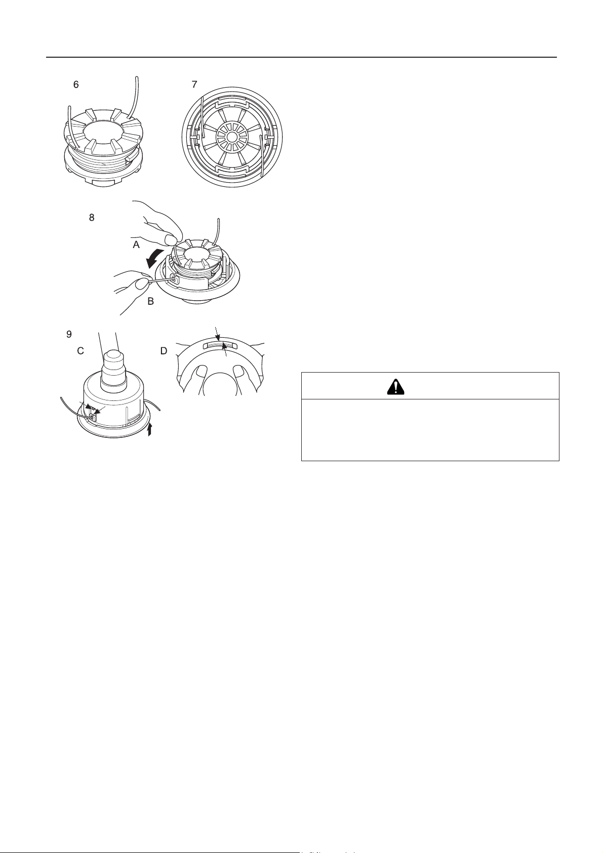
1. Press "retaining pawls" (at two places) inward and remove
cover. It is easier to remove one after another.
2. Remove spool.
3. When nylon line on the spool is almost exhausted, remove
remaining line from spool and wind "new line" according to
the procedures (4) and beyond. When the line on the spool
is "melted and stuck" remove the entire line while peeling off
the "melted and stuck" portion and wind the "removed line"
anew according to procedures (4) and beyond.
4. Bend the line at the point 12 cm away from the middle of
whole length and hook the bent portion into the "notch" of the
intermediate separator.
5. Wind the line firmly into groove of the spool following "winding direction for the arrow".
25
Page 28
Maintenance and care
6. When the line is wound to the end hook both line ends into
respective notch of spool for retaining tentatively the line
while leaving line ends approximately 10 cm beyond notch.
7. Align notches of spool for the line with grooves of eyelets
and fit spool into cover.
8. Pull out the line from cover. (A) Remove the line from "respective notch of spool", and (B) pass it through "groove of
respective eyelet".
9. Fit cover and housing together. (C) Align "eyelets" of cover
with "recesses" of housing, and (D) press pawls of housing
into respective window of cover until the pawls are firmly fitted into the windows.
DANGER
Make sure each outer periphery of pawls of housing
spreads almost fully up to the outer periphery of respective window of cover. If they are loosely fitted and the cutting head is turned, cover or inside components can fly off
which is dangerous.
26
Page 29

Maintenance and care
Troubleshooting table
IMPORTANT
For spare parts and consu mables, please use only genuine parts and designated products and components.
Using parts from other manufacturers or non-designated components may result in a malfunction.
Problem Diagnosis Cause Solution
The engine does
not start
Engine is difficult to
start, fluctuating rotation
Engine starts but
no acceleration is
possible
The engine stops 1. Carburettor adjustment problem
The engine fails to
stop
Cutting attachment
rotates when the
engine is idling
Fuel is entering the overflow
pipe
No fuel is entering the overflow pipe
The spark plug is dirty or
damp
1. There is no fuel in the fuel tank
2. The stop switch is in the Stop position
3. Excess fuel suction
4. Electrical fault
5. Carburettor malfunction or internal sticking
6. Internal engine malfunction
1. Fuel degradation
2. Carburettor problem
1. Fuel filter is clogged
2. Fuel system is clogged
3. Internal carburettor parts sticking
1. Fuel degradation
2. Incorrect electrode gap
3. Carbon deposits
4. Electrical fault
1. Dirty air filter
2. Dirty fuel filter
3. Blocked fuel passage
4. Carburettor adjustment problem
5. Blocked exhaust vent or silencer vent
2. Electrical fault
1. Stop switch malfunction 1. Perform an emergen-
1. Carburettor adjustment problem
2. Damaged clutch spring
1. Fuel supply
2. Move to the Start position
3. Start the engine after
servicing
4. Consult your dealer
5. Consult your dealer
6. Consult your dealer
1. Replace with new fuel
2. Consult your dealer
1. Clean or replace
2. Consult your dealer
3. Consult your dealer
1. Replace
2. Replace
3. Replace
4. Consult your dealer
1. Clean or replace
2. Clean or replace
3. Consult your dealer
4. Adjust
5. Clean
1. Adjust
2. Consult your dealer
cy stop and consult
your dealer
1. Adjust
2. Consult your dealer
Consult your dealer in the event of a problem that is not covered in the table above, or other such concerns.
Please contact your dealer in order to dispose of the product or its parts in compliance with national laws.
27
Page 30
Maintenance and care
Manufacturer:
YAMABIKO CORPORATION
7-2 SUEHIROCHO 1-CHOME, OHME, TOKYO 198-8760, JAPAN
Authorized Representative in Europe:
Atlantic Bridge Limited
Atlantic House, PO Box 4800, Earley, Reading RG5 4GB, United Kingdom
Storage
Long-term storage (30 days or more)
WARNING
Do not store in sealed locations filled with fuel gas, or close to naked flames or sparks.
You could cause a fire.
When storing the product for long periods of time (30 days or more), ensure that the following preparations for storage are carried
out.
1. Remove any fuel from the fuel tank.
2. Alternately press and release the purge bulb a number of
times to remove the fuel from the purge bulb.
3. Start the engine and run it at idle speed until it comes to a
natural stop.
4. Move the ignition switch (A) to the Stop position.
5. Once the product is sufficiently cool, wipe clean any grease,
oil, dust, dirt and other materials on the outside of the trimmer.
6. Perform the periodic checks prescribed in this manual.
7. Check that the screws and nuts are tightened. Tighten up
any that are loose.
8. Remove the spark plug (B) and add the appropriate quantity
(around 10 mL) of clean, new 2-stroke engine oil to the cylinder via the installation socket.
9. Place a piece of clean cloth over the spark plug installation
socket.
10. Pull 2 or 3 times on the starter grip to distribute the engine oil
into the cylinder.
11. Observe the piston location through the spark plug hole. Pull
the recoil starter handle slowly until the piston reaches the
top of its travel and leave it there.
12. Fit the spark plug. (Do not connect the spark plug cap (C).)
13. Fit the blade cover onto the trimmer bla de and wrap the engine section in a plastic bag or other covering, and store in a
dry, dust-free location out of reach of children.
28
Page 31

Specifications
Specifications
RM-520ES
External dimensions:
Length × Width × Height 2828 × 449 × 564 mm
Mass:
Unit without fuel, cutting attachment and guard (ISO11806)
Unit with fuel, specified cutting attachment, guard and harness
Volume: Fuel tank 1.0 L
Cutting attachment:
Nylon line cutting head
Nylon line head Cutting width (Cutting Swath)
Specified blade diameter (option)
Specified blade thickness (option)
Number of cutting teeth (option)
Blade centre hole diameter
Blade rotational speed at maximum allowable engine speed
Gear ratio: Gear ratio and lubrication 1.33 reduction and high-temperatuire, long-life grease
Rotational direction of output shaft seen from above: Anticlockwise
Engine:Type Air cooled 2-stroke single cylinder
Engine displacement
Maximum shaft brake power, measured in accordance with ISO 8893
Engine speed at maximum engine power
Recommended maximum engine speed (With STD attachment installed)
Recommended engine idling speed
Carburettor
Ignition
Spark plug
Starter
Clutch
12.0 kg
13.7 kg
Z5
430 mm
255 mm
3.0 mm
3
25.4 mm
10000 r/min
3
50.2 mL (cm
2.16 kW
9000 min
10900 min
2800 min
)
-1
-1
-1
Diaphragm type
Flywheel magneto - CDI system
NGK BPMR8A
Recoil starter
Automatic centrifugal clutch
Fuel:
Regular grade petrol. Minimum 89 Octane unleaded
petrol is recommended. Do not use fuel containing methyl alcohol or more than 10% of ethyl alcohol.
Oil
Two stroke, air-cooled engine oil. ISO-L-EGD Standard
(ISO/CD 13738), JASO FC,FD grade and ECHO Premium 50:1 oil.
Ratio
Fuel consumption at maximum engine power
Specific fuel consumption at maximum engine power
Vibration levels: (ISO 22867)a
hv,eq
50:1 (2%)
1.23 L/h
423 g/kW•h
Front handle 5.3 m/s
Rear handle 4.0 m/s
Uncertainty 1.2 m/s
Sound pressure level: (ISO 22868) LpAeq 97.5 dB(A)
Uncertainty 1.5 dB(A)
Guaranteed sound power le v el:(ISO 22868) L
WA
114 dB(A)
These specifications are subject to change without notice.
2
2
2
29
Page 32

Declaration of conformity
The undersigned manufacturer:
YAMABIKO CORPORATION
7-2 SUEHIROCHO 1-CHOME
OHME; TOKYO 198-8760
JAPAN
This declaration of conformity is issued under the sole responsibility of the manufacturer.
declares that the hereunder specified new unit:
GRASS-TRIMMER/BRUSHCUTTER
Brand: ECHO
Type: RM-520ES
complies with:
* the requirements of Directive 2006/42/EC (use of harmonized standard ISO 11806-2: 2011)
Declaration of conformity
* the requirements of Directive 2004/108/EC (use of harmonized standard EN ISO 14982: 2009)
* the requirements of Directive 2000/14/EC
Conformity assessment procedure followed ANNEX V
Measured sound power level: 111 dB(A)
Guaranteed sound power level: 114 dB(A)
Serial Number 37001001 and up
Tokyo, October 1st 2015
YAMABIKO CORPORATION
The authorized representative in Europe who is authorized to
compile the technical file.
Company: Atlantic Bridge Limited
Address: Atlantic House, PO Box 4800, Earley, Reading RG5
4GB, UK
Masayuki Kimura Mr. Philip Wicks
General Manager
Quality Assurance Dept.
30
Page 33

1Notes and rear cover
MEMORANDUM
2015
X750-026430
X750222-7500
31
Page 34

7-2 SUEHIROCHO 1-CHOME, OHME, TOKYO 198-8760, JAPAN
PHONE: 81-428-32-6118. FAX: 81-428-32-6145.
©
2015
X750-026430
X750222-7500
Printed in Japan
0x0xxxx zzzz ES
32
Page 35

1Couverture
FRANÇAIS
(Notice originale)
MANUEL D'UTILISATION
COUPE-HERBE/DÉBROUSSAIL-
LEUSE
RM-520ES
AVERTISSEMENT
LIRE ATTENTIVEMENT LES INSTRUCTIONS ET SUIVRE LES
RÈGLES DE SECURITÉ.
LE NON-RESPECT DES RÈGLES DE SÉCURITÉ ENTRAÎNE UN
RISQUE DE BLESSURE GRAVE.
Page 36

Table des matieres
Pour utiliser l'appareil en toute sécurité..............................................................................3
Description..........................................................................................................................8
Avant de commencer.................................... ... .... ... ... ... .... ... ... ... .... ... ... ... ... .... ... ... ...............9
Contenu de l'emballage........ ... ... .... ... ................................................... .... ... ... ... .... ... ... .. 9
Assemblage.................................................................................................................10
Préparation du carburant.............................................................................................12
Fonctionnement du moteur...............................................................................................13
Démarrage du moteur..................................................................................................13
Arrêt du moteur............................................................................................................14
Utilisation de l'appareil......................... ... ... ... ... .... ... ... ... .... ... ... ... .... ... ... ... ..........................15
Utilisation de base de l'appareil avec tête de coupe à fil nylon ...................................16
Utilisation de base de l'appareil avec lame métallique ................................................19
Entretien ...........................................................................................................................20
Instructions d'entretien de l'appareil ........... .... ... ... ... .... ... ... ... .... ... ... .............................20
Entretien ......................................................................................................................20
Remisage ....................................................................................................................29
Caractéristiques................................................................................................................30
Déclaration de conformité.................................................................................................31
2
Page 37

Pour utiliser l'appareil en toute sécurité
Pour utiliser l'appareil en toute sécurité
Information importante
AVERTISSEMENT
Lire attentivement le manuel d'utilisation avant d'utiliser l'appareil pour la première fois.
À propos du manuel d'utilisation
Ce manuel contient les informations nécessaires au montage, à l'utilisation et à l'entretien de l'appareil. L'utilisateur
doit donc le lire attentivement et intégrer les informations qu'il contient.
Toujours conserver le manuel à portée de main.
En cas de perte du manuel ou si ce dernier a été détérioré et n'est plus lisible, s'adresser à un revendeur pour en
obtenir un nouveau.
Les unités utilisées dans ce manuel sont les unités SI (Système international d'unités). Les chiffres indiqués entre
parenthèses sont des valeurs de référence. De légères erreurs de conversion peuvent survenir dans certains cas.
Le non-respect de cette règle de sécurité entraîne un risque d'accident ou de blessure grave.
Utilisation de l'appareil
Ces machines sont légères, très performantes, équipées d'un moteur à essence et conçues pour désherber, tondre
et débroussailler dans des endroits inaccessibles par d'autres moyens.
Ne pas utiliser cet appareil pour d'autres applications que celles mentionnées ci-dessus.
YAMABIKO se réserve le droit de modifier sans préavis le contenu de ce manuel en fonction des améliorations apportées au produit. Il se peut que certains des schémas de ce manuel soient différents de l'appareil. Ces différences
ont pour objectif de rendre les explications plus claires.
En cas de doute, consulter un revendeur.
Le non-respect de cette règle de sécurité entraîne un risque d'accident ou de blessure grave.
Ne pas modifier l'appareil
Aucune modification ne doit être apportée à l'appareil.
Le non-respect de cette règle de sécurité entraîne un risque d'accident ou de blessure grave. Tout dysfonctionnement dû à
une modification de l'appareil n'est pas couvert par la garantie du fabricant.
Ne pas utiliser l'appareil avant d'avoir effectué les opérations de vérification et d'entretien nécessaires
Il ne faut pas utiliser l'appareil avant d'avoir effectué les opérations de vérification et d'entretien nécessaires. Veiller
à ce que l'appareil soit vérifié et entretenu régulièrement.
Le non-respect de cette règle de sécurité entraîne un risque d'accident ou de blessure grave.
Prêt ou cession de l'appareil à un tiers
Si l'appareil est prêté à un tiers, veiller à lui confier également le manuel d'utilisation fourni avec l'appareil.
Si l'appareil est cédé à un tiers, transmettre le manuel d'utilisation fourni avec l'appareil lors de la vente.
Le non-respect de cette règle de sécurité entraîne un risque d'accident ou de blessure grave.
Utilisateurs de l'appareil
L'appareil ne doit pas être utilisé si :
l'utilisateur est fatigué
l'utilisateur a consommé de l'alcool
l'utilisateur prend des médicaments
la personne qui souhaite utiliser l'appareil est enceinte
l'utilisateur est en mauvaise condition physique
l'utilisateur n'a pas lu le manuel d'utilisation
la personne qui souhaite utiliser l'appareil est un enfant
L'utilisateur est tenu pour responsable en cas d'accidents ou de risques pouvant entraîner des accidents corporels
ou des dommages matériels.
Le non-respect de ces règles de sécurité constitue un risque d'accident.
Le système d'allumage de cet appareil produit des champs électromagnétiques lorsqu'il fonctionne. Les champs
magnétiques peuvent provoquer des interférences ou des pannes sur les stimulateurs cardiaques. Pour réduire les
risques pour la santé, nous recommandons aux porteurs d'un stimulateur cardiaque de consulter leur médecin et le
fabricant du stimulateur avant d'utiliser cet appareil.
3
Page 38

Pour utiliser l'appareil en toute sécurité
AVERTISSEMENT
Exposition aux vibrations et au froid
Les personnes exposées aux vibrations et au froid peuvent être victimes du phénomène de Raynaud, une affection
qui touche les doigts. L'exposition à des vibrations et au froid peut provoquer une sensation de picotement et de
brûlure, suivie d'une décoloration et d'un engourdissement des doigts. Il est vivement recommandé de respecter les
mesures de précaution suivantes car le seuil d'exposition minimum pouvant provoquer l'apparition de ce phénomène reste inconnu à ce jour.
Limiter la perte de chaleur corporelle, en protégeant en priorité la tête, le cou, les pieds, les chevilles, les mains
et les poignets.
Stimuler la circulation sanguine en interrompant le travail régulièrement pour remuer énergiquement les bras, et
éviter de fumer.
Limiter le nombre d'heures d'utilisation. Essayer d'intégrer à l'emploi du temps de la journée des tâches ne né-
cessitant pas l'utilisation de l'appareil ou d'une autre machine portative.
En cas d'inconfort, de rougeur et de gonflement au niveau des doigts, suivis d'un blanchissement et d'une perte
de sensibilité, consulter un médecin avant de s'exposer à nouveau au froid et aux vibrations.
Le non-respect de ces instructions peut être dangereux pour la santé.
Lésions attribuables au travail répétitif
Il apparaît que la sollicitation excessive des muscles et des tendons des doigts, des mains, des bras et des épaules
peut provoquer une irritation, un gonflement, un engourdissement, une faiblesse et de fortes douleurs au niveau des
membres mentionnés ci-dessus. L'apparition de lésions attribuables au travail répétitif (LATR) est très fréquente
chez les personnes pratiquant certaines activités manuelles répétitives. Pour réduire le risque d'apparition de LATR,
respecter les mesures de précaution suivantes :
Éviter de plier, d'étirer ou de tordre le poignet pendant le travail.
Faire des pauses régulières pour réduire l'effet répétitif et pour reposer ses mains. Effectuer le mouvement répé-
titif plus lentement et en faisant moins d'effort.
Faire des exercices de musculation des mains et des bras.
En cas de picotements, d'engourdissement ou de douleur dans les doigts, les mains, les poignets ou les bras,
consulter un médecin. Plus les LATR sont diagnostiquées précocement, plus les chances d'empêcher les lésions
nerveuses et musculaires irréversibles sont grandes.
Le non-respect de ces instructions peut être dangereux pour la santé.
Une formation adaptée
Toute personne devant utiliser cet appareil doit obligatoirement avoir reçu une formation et un équipement de protection adaptés.
Vous devez avoir une connaissance parfaite des commandes et du fonctionnement de l'appareil.
Vous devez savoir comment arrêter l'appareil et couper le moteur.
Vous devez savoir comment décrocher la machine du harnais en urgence.
Ne laisser personne utiliser l'appareil sans avoir préalablement reçu une formation adaptée.
Le non-respect de ces instructions peut être dangereux pour la santé.
Port de vêtements adaptés
Attacher les cheveux longs au-dessus du niveau de l'épaule.
Ne pas porter de cravates, bijoux ou vêtements amples qui pourraient se prendre dans
l'appareil.
Ne pas porter de chaussures ouvertes, ne pas travailler pieds nus ou jambes nues.
Le non-respect de ces mesures de précaution peut entraîner une dégradation de la vue ou de
l'ouïe de l'utilisateur, ainsi qu'un risque de blessure grave.
4
Page 39

Pour utiliser l'appareil en toute sécurité
AVERTISSEMENT
Port d'équipements de protection
Toujours porter les équipements de protection suivants pour utiliser un coupeherbe.
1. Protection de la tête (casque) : protège la tête.
2. Casque de protection anti-bruit ou protecteurs d'oreilles : protègent l'ouïe.
3. Lunettes de sécurité : protègent les yeux.
4. Protection du visage : protège le visage.
5. Gants de sécurité : protègent les mains contre le froid et les vibrations.
6. Vêtements de travail adaptés (manches longues, pantalons longs) : pro-
tègent le corps.
7. Bottes résistantes avec semelles anti-dérapantes (à bouts renforcés) ou
chaussures de travail avec semelles anti-dérapantes (à bouts renforcés) : pro-
tègent les pieds.
8. Protège-tibias : protègent les jambes.
Le non-respect de ces mesures de précaution peut entraîner une dégradation de la vue
ou de l'ouïe de l'utilisateur, ainsi qu'un risque de blessure grave.
Si nécessaire, utiliser les équipements de protection ci-dessous.
Masque anti-poussière : protège les voies respiratoires
Voilette de protection : protège contre les piqûres d'abeilles
Environnement d'utilisation et fonctionnement de l'appareil
Ne pas utiliser l'appareil :
en cas de mauvaises conditions météo.
sur des pentes raides ou sur des surfaces instables et glissantes ;
la nuit ou dans des endroits sombres mal éclairés.
Lorsque vous utilisez l'appareil sur un terrain en pente douce, employez un mouvement régulier et gardez la tête de
coupe parallèle au sol.
Toute chute, glissade ou utilisation incorrecte de l'appareil constitue un risque de blessures graves pour l'utilisate ur.
Afin de préserver votre santé et de travailler dans des conditions de sécurité et de confort optimales, utiliser l'appareil uniquement par des températures comprises en tre -5
Le non-respect de ces instructions peut être dangereux pour la santé.
o
C et 40 oC.
Savoir réagir en cas de blessure
Même si les cas de blessure ou d'accident restent exceptionnels, l'utilisateur doit savoir réagir à ces situations.
Kit de premiers secours
Serviettes et lingettes (pour arrêter les saignements)
Sifflet ou téléphone portable (pour appeler de l'aide)
Si l'utilisateur n'est pas capable de prodiguer les premiers soins ou d'appeler à
l'aide, la blessure peut s'aggraver.
Le bon réflexe en cas d'incendie ou de fumée
Si le moteur prend feu ou si de la fumée s'échappe de l'appareil à un autre endroit que la sortie d'échappement, la première chose à faire est de s'éloigner de l'appareil pour éviter tout risque d'accident.
À l'aide d'une pelle, jeter du sable ou un autre matériau équivalent sur les flammes pour éviter que l'incendie ne se propage, ou éteindre les flammes avec un extincteur.
Ne pas céder à la panique permet d'éviter que l'incendie ne se propage et donc de limiter l'étendue des dégâts.
Etiquettes et symboles d'avertissement
DANGER AVERTISSEMENT ATTENTION
Ce symbole associé au mot
« DANGER » signale une action ou
une situation présentant un risque de
blessure corporelle grave ou d'accident mortel pour l'utilisateur et les
personnes à proximité.
Ce symbole associé au mot
« AVERTISSEMENT » signale une
action ou une situation présentant un
risque de blessure corporelle grave
ou d'accident mortel pour l'utilisateur
et les personnes à proximité.
« ATTENTION » signale une situation potentiellement dangereuse qui,
si elle n'est pas évitée, peut entraîner
une blessure légère à modérée.
5
Page 40

Pour utiliser l'appareil en toute sécurité
Autres indications
REMARQUE IMPORTANT
Le cercle barré indique
une interdiction.
Symboles
Ce type de message fournit des
conseils relatifs à l'utilisation et à l'entretien de l'appareil.
Le texte dans l'encadré où figure le
mot «IMPORTANT» donne des in-
formations importantes concernant
l'utilisation, la vérification, l'entretien
et le remisage de l'appareil décrit
dans ce manuel.
Forme des symboles Description/application des
symboles
Lire attentivement le manuel
d'utilisation
Port obligatoire de protections
pour les yeux, les oreilles et la
tête
Port obligatoire de chaussures
et de gants de protection
Arrêt d'urgence
Avertissement !
Projections !
Forme des symboles Description/application des
symboles
Vitesse maximale de l'arbre
de l'outil de coupe en
tr/min
Ne laisser personne s'approcher à moins de 15 mètres
Mélange d'essence et d'huile
Commande de starter en position « Démarrage à froid »
(starter fermé)
Commande de starter en position « Marche » (starter ouvert)
Attention, poussée latérale
Ne pas utiliser sans protecteur
d'outil
Interdiction d'utiliser des
lames métalliques
Interdiction d'utiliser une tête
de coupe à fil nylon
Réglage du carburateur
- Régime de ralenti
Lubrifier toutes les 18 heures
Poignée semi-circulaire
Attention aux températures
élevées
6
Page 41

Pour utiliser l'appareil en toute sécurité
Forme des symboles Description/application des
symboles
Ne pas utiliser l'appareil dans
des endroits mal aérés
Attention aux risques d'incendie
Attention aux risques de choc
électrique
Forme des symboles Description/application des
symboles
Niveau de puissance sonore
garanti
Démarrage du moteur
-
Étiquette(s) de sécurité
L'étiquette de sécurité ci-dessous figure sur les appareils décrits dans ce manuel. S'assurer de bien comprendre la signification
de l'étiquette avant d'utiliser l'appareil.
Si l'étiquette devient illisible avec le temps ou si elle s'est décollée ou a été déchirée, contacter un revendeur pour obtenir une
nouvelle étiquette et la coller à l'emplacement indiqué sur les illustrations ci-dessous. Veiller à ce que l'étiquette soit toujours
lisible.
1. Etiquette de sécurité (numéro de pièce 890617-43130)
7
Page 42

Description
Description
1. Outil de coupe. - Tête de coupe à fil nylon pour couper
l'herbe et les mauvaises herbes.
2. Protecteur d'outil. - Protège l'utilisateur contre les projections et empêche tout contact accidentel avec la tête
de coupe.
3. Renvoi d'angle. - Avec deux engrenages pour changer
l'angle de l'axe de rotation.
4. Tube de transmission - Pièce de l'appareil qui protège
l'arbre de transmission.
5. Poignée avant. - Poignée située près de l'outil de
coupe.
6. Interrupteur marche/arrêt. « Interrupteur à glissière »
monté sur le dessus du boîtier de la gâchette d'accélérateur. Basculer l'interrupteur vers le haut pour
MARCHE, vers le bas pour ARRET.
7. Gâchette d'accélérateur. Activée par le doigt de l'utili-
sateur pour contrôler le régime moteur.
8. Blocage de la gâchette. Bloque la gâchette en position
de ralenti jusqu'à ce que l'utilisateur puisse positionner
correctement sa main droite sur la poignée.
9. Poignée arrière. - Poignée située vers le groupe mo-
teur dorsal.
10. Ensemble de tige flexible. - Tube flexible de l'arbre de
transmission.
11. Trousse à o utils - trousse amovible pour outils et accessoires.
12. Couvercle de silencieux - protection empêchant tout
contact avec la surface brûlante du silencieux.
13. Bougie d'allumage
14. Poignée de lanceur - Tirer sur la poignée pour démarrer le moteur.
15. Réservoir de carburant - Contient le carburant et le
filtre à carburant.
16. Couvercle de filtre à air - couvre le filtre à air.
17. Bouchon du réservoir de carburant - assure la ferme-
ture du réservoir de carburant.
8
Page 43

Avant de commencer
Avant de commencer
Contenu de l'emballage
Les pièces suivantes sont conditionnées séparément dans le carton d'emballage.
Lors de l'ouverture du carton, passer en revue les pièces qu'il contient.
Contacter un revendeur si une pièce est manquante ou endommagée.
Moteur
Barre de travail
1. Moteur
2. Gâchette d'accélérateur
3. Outil de blocage
4. Clé à pipe
5. Clé coudée
6. Lunettes de sécurité
7. Étiquette de sécurité
8. Protection en plastique
9. Poignée avant
10. Tête de coupe à fil nylon
11. Sangle
12. Manuel d'utilisation
13. Protecteur d'outil (pour tête de coupe à fil nylon)
14. Protecteur d'outil (pour lame métallique)
15. Ensemble de tige flexible
16. Tube de transmission
9
Page 44
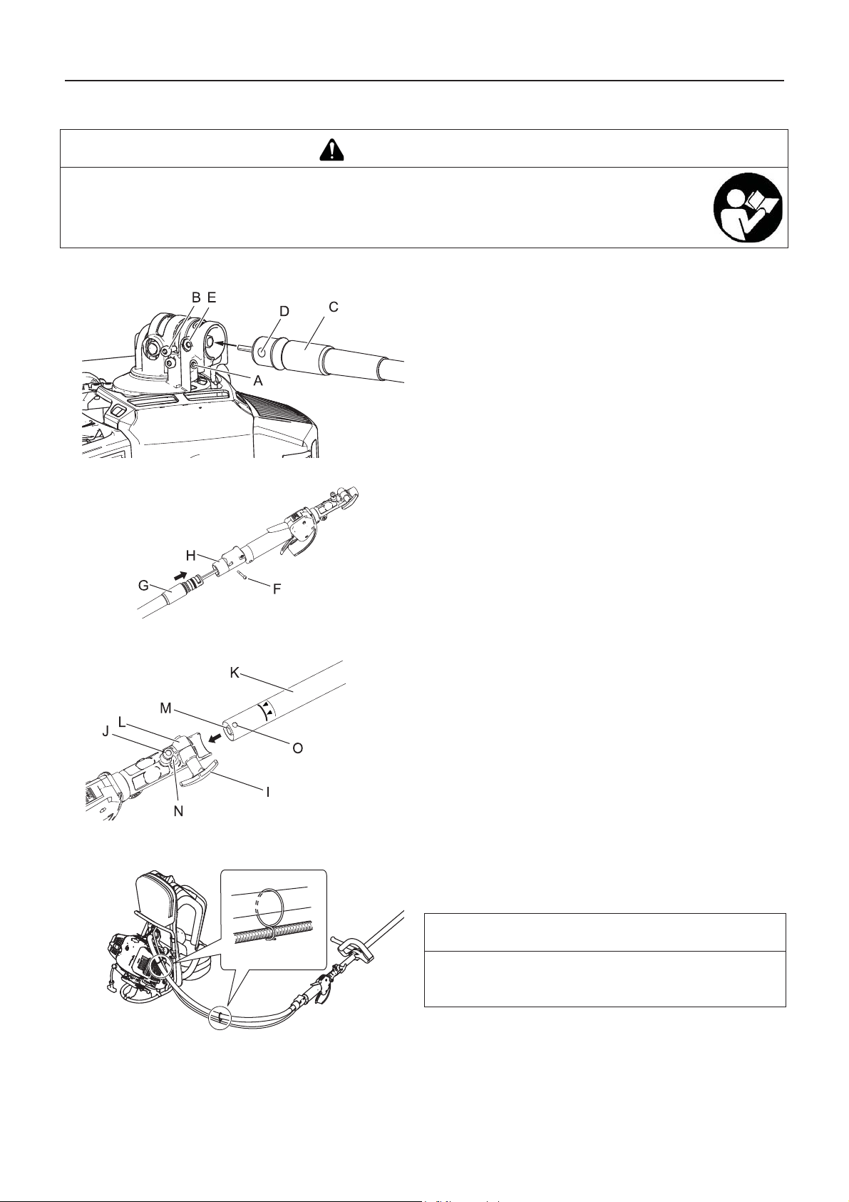
Avant de commencer
Assemblage
AVERTISSEMENT
Lire attentivement le manuel d'utilisation pour s'assurer que l'appareil est monté correctement.
L'utilisation d'un appareil monté de façon incorrecte entraîne un risque d'accident ou de blessure grave.
Assemblage de la barre de travail
1. Desserrer le boulon (A).
2. Desserrer l'ergot d'arrêt (B).
3. Insérer l'ensemble de tige flexible (C) dans le renvoi d'angle.
4. Aligner l'orifice de l'ensemble de tige flexible (D) avec l'orifice du renvoi d'angle (E).
5. Serrer l'ergot d'arrêt et le boulon.
6. Retirer l'ergot d'arrêt (F).
7. Insérer l'ensemble de tige flexible (G) dans le tuyau de la gâchette.
8. Serrer l'ergot d'arrêt.
9. Dévisser le bouton de serrage (I).
10. Tirer la goupille de positionnement (J) et la tourner d'1/4 de
tour dans le sens inverse des aiguilles d'une montre en position de blocage.
11. Insérer l'ensemble de la barre de travail (K) dans le coupleur
(L) tout en alignant la douille (M) avec la tige flexible (N).
12. Tourner la goupille de positionnement de 1/4 de tour dans le
sens des aiguilles d'une montre pour l'enclencher dans l'orifice de la barre de travail. Vérifier que la goupille de positionnement est bien enclenchée en tournant la barre de travail.
La goupille de positionnement doit parfaitement s'enclencher dans le coupleur. Ainsi, l'arbre ne peut plus tourner.
13. Serrer l'ergot d'arrêt.
14. Les deux colliers fixés à l'ensemble de tige flexible doivent
être placés aux positions adéquates sur le câble de l'accélérateur (à égale distance sur la longueur de la tige flexible).
REMARQUE
Pour le démontage, inverser les instructions de montage.
Insérer la protection en plastique dans le coupleur afin d'éviter une fuite de graisse.
10
Page 45
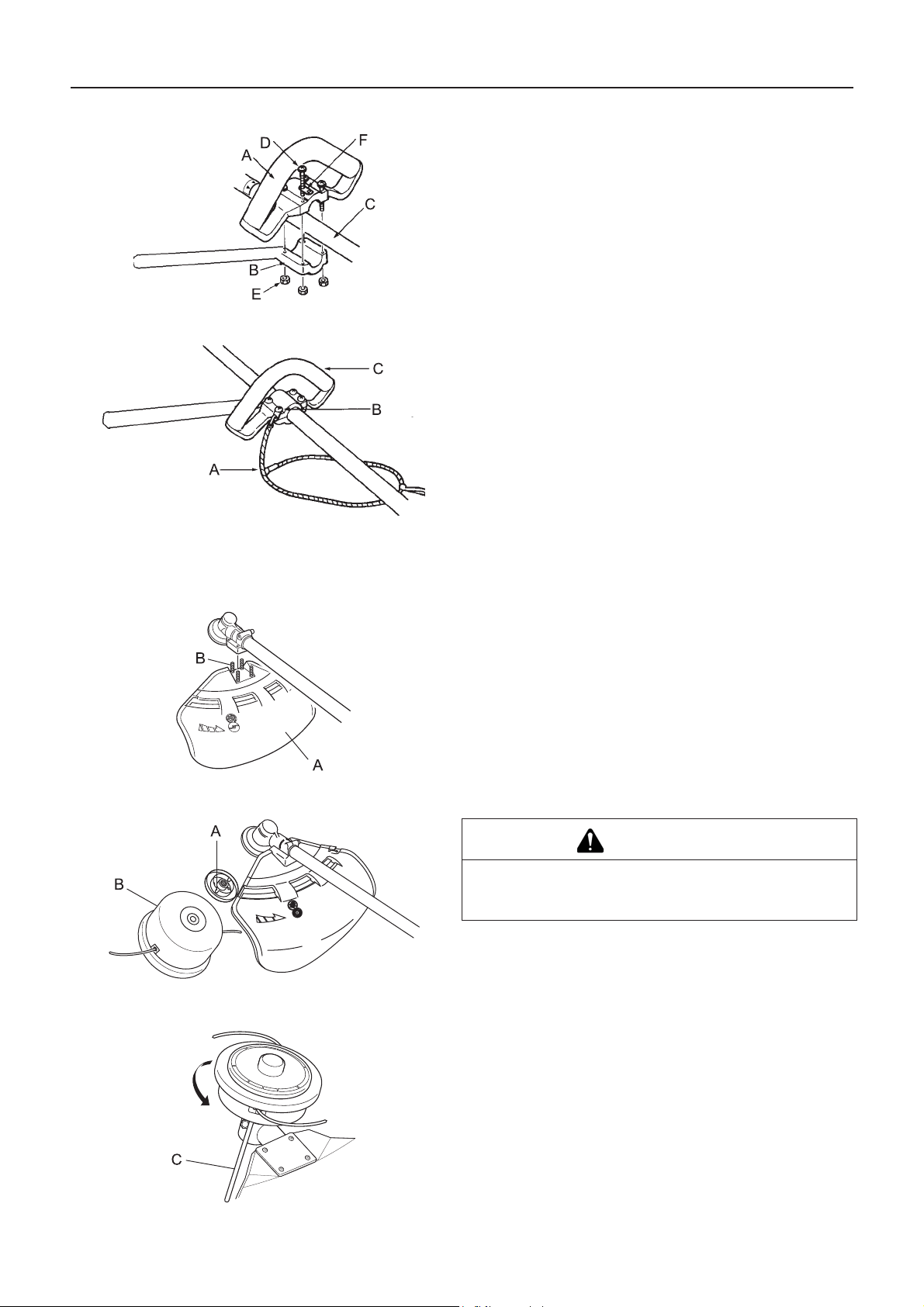
Assemblage de la poignée semi-circulaire
Harnais
Avant de commencer
1. Monter la poignée avant (A) et le support (B) sur le tube de
transmission (C) sans les serrer.
2. Ajuster la position de la poignée avant pour optimiser le
confort d'utilisation.
3. Serrer fermement les vis (M5×35) (D) et les écrous (E). Une des 4 vis doit être fixée sur la plaque de fixation (F)
comme illustré.
1. Régler la longueur de la bandoulière supportant le groupe
moteur dorsal pour assurer un confort optimal.
2. La sangle étant élastique et réglable, il est recommandé de
relier la sangle (A) aux plaques de fixation (B) situées sur la
poignée avant (C) et sur la bandoulière gauche ou droite du
groupe moteur dorsal afin de permettre une utilisation facile
et confortable.
1. Poignée avant
2. Plaque de fixation
3. Sangle
Montage du protecteur d'outil
Montage de la tête de coupe à fil nylon
1. Placer le protecteur d'outil (A) sur la zone de fixation du renvoi d'angle et serrer 4 boulons (B).
ATTENTION
Fixer solidement l'arbre de sortie à l'aide de l'outil de
blocage pour éviter qu'il ne tourne lors d e la pose d e la
tête de coupe à fil nylon.
1. Insérer l'outil de blocage dans l'orifice situé sur le côté droit
du renvoi d'angle tout en poussant le ressort de retenue vers
la gauche.
2. Enfoncer l'outil de blocage dans le trou de blocage de
flasque (A) pour fixer l'arbre de sortie.
3. Visser la tête de coupe à fil nylon (B) sur l'arbre (dans le sens
inverse des aiguilles d'une montre) en s'assurant qu'elle est
bien serrée.
4. Retirer l'outil de blocage (C).
11
Page 46

Avant de commencer
Préparation du carburant
DANGER
Il est interdit de ravitailler l'appareil lorsque le moteur est chaud ou en marche.
Il est interdit de fumer lors du ravitaillement. Effectuer le ravitaillement à l'écart de toute flamme.
En effet, le carburant risque de s'enflammer et de provoquer un incendie, entraînant ainsi un risque de brûlure.
AVERTISSEMENT
NE JAMAIS remplir les réservoirs de carburant dans un endroit fermé. TOUJOURS remplir les réservoirs de carburant à l'extérieur, à même le sol. Ne jamais ravitailler l'appareil sur la plate-forme de chargement d'un camion ou autre
endroit du même type.
Les bidons/réservoirs de carburant peuvent être sous pression. Toujours desserrer le bouchon du réservoir de carburant de façon progressive pour permettre l'égalisation de la pression.
Dans le cas contraire, le carburant risque de se déverser.
Essuyer le carburant renversé en cas de débordement ou de trop plein du réservoir.
Tout déversement de carburant, s'il s'enflamme, entraîne un risque d'incendie et de brûlure.
Après le ravitaillement, toujours vérifier qu'il n'y a pas de fuite ou d'écoulement de carburant au niveau du tuyau de
carburant, du passe-tuyau de carburant ou autour du bouchon du réservoir de carburant. En cas de fuite ou d'écoulement de carburant, interrompre immédiatement l'utilisation de l'appareil et contacter un revendeur pour effectuer
les réparations nécessaires.
Toute fuite de carburant entraîne un risque d'incendie.
Entreposer le réservoir de ravitaillement dans un endroit ombragé et loin de toute flamme.
Utiliser un réservoir de carburant agréé.
IMPORTANT
Le carburant est un mélange d'essence ordinaire et d'une huile moteur de grande marque pour moteur deux temps à refroi-
dissement par air. Il est conseillé d'utiliser de l'essence sans plomb avec un indice d'octane 89 au minimum. Ne pas utiliser
de carburant contenant du méthanol ou plus de 10 % d'éthanol.
Le carburant vieillit lorsqu'il est stocké. Ne préparer qu'une quantité de carburant suffisante pour une consommation de trente
(30) jours.
Carburant
Richesse du mélange recommandée ; 50 : 1 (2%) selon la
norme ISO-L-EGD (ISO/CD 13738), la norme JASO FC,FD et
l'huile ECHO Premium 50 : 1.
Ne pas faire le mélange directement dans le réservoir de car-
burant.
Alimentation en carburant
Ne pas remplir le réservoir de carburant (A) jusqu'en haut.
Remplir le réservoir jusqu'au niveau recommandé (jusqu'à
l'épaulement (B) du réservoir de carburant).
Une fois le ravitaillement effectué, revisser fermement le bou-
chon du réservoir de carburant.
12
Page 47

Fonctionnement du moteur
Fonctionnement du moteur
Démarrage du moteur
AVERTISSEMENT
Veiller à bien respecter les mesures de précaution suivantes lors du démarrage du moteur :
S'éloigner d'au moins 3 mètres de l'endroit où le ravitaillement a été effectué.
Placer l'appareil sur une surface plane et dans un endroit bien aéré.
Vérifier qu'il n'y a pas de fuite de carburant.
Inspecter les lames métalliques pour repérer les fissures.
Vérifier que tous les écrous et toutes les vis sont bien serrés.
Établir un périmètre de sécurité autour de l'appareil et s'assurer que personne ni aucun animal ne se trouve à proximité.
Pour le démarrage du moteur, mettre la gâchette d'accélérateur en position de régime de ralenti.
Maintenir fermement l'appareil au sol lors du démarrage du moteur.
Le non-respect de ces mesures de précaution constitue un risque d'accident et de blessures graves voire mortelles.
Au démarrage du moteur, vérifier l'absence de vibrations et de sons anormaux. Ne pas utiliser l'appareil en cas de
vibrations ou de sons anormaux. Contacter un revendeur pour effectuer les réparations nécess aires.
La chute ou la rupture accidentelle de pièces constitue un risque de blessures graves.
Les fumées d'échappement du moteur contiennent des gaz toxiques. Ne pas utiliser l'appareil dans un
endroit fermé ou mal aéré.
Il existe un risque d'intoxication due aux fumées d'échappement.
Ne pas toucher le silencieux, la bougie d'allumage, le renvoi de transmission et autres composants sous
haute température lors du fonctionnement de l'appareil et pendant la phase qui suit l'arrêt de l'appareil.
Il existe un risque de brûlure en cas de contact avec un composant à haute température.
Ne pas toucher la bougie d'alluma ge, le fil de la bougie d'allumage, et les composants sous haute tension lors du fonctionnement de l'appareil .
Il existe un risque de choc électrique en cas de contact avec un composant sous haute tension pendant le fonctionnement de l'appareil.
Si une fois le moteur allumé, l'outil de coupe tourne alors que la gâchette d'accélérateur est positionnée sur le régime
de ralenti, régler le carburateur avant d'utiliser l'appareil.
Le non-respect de ces mesures de précaution constitue un risque d'accident et de blessures graves voire mortelles.
REMARQUE
Tirer la poignée de lanceur, doucement dans un premier temps, puis plus rapidement. Ne pas tirer la corde de lanceur à plus
de 2/3 de sa longueur.
Ne pas lâcher la poignée de lanceur lorsqu'elle revient.
Démarrage du moteur à froid
(Connecter le protecteur de bougie si l'appareil n'a pas fonctio nné depuis longtemps.)
1. Retirer l'étui protecteur de lame.
2. Après avoir posé l'appareil sur une surface plane, vérifier
que l'outil de coupe n'est pas en contact avec le sol ou avec
d'autres obstacles, en utilisant une poutre ou un autre objet
similaire.
3. Placer l'interrupteur marche/arrêt (A) en position Marche
(Start).
4. Veiller à ce que la gâchette d'accélérateur (D) soit en position de régime de ralenti.
13
Page 48

Fonctionnement du moteur
5. Placer la manette de starter (F) en position « Démarrage à
6. Comprimer et relâcher la pompe d'amorçage (H) jusqu'à ce
7. Après avoir vérifié que la zone entourant l'utilisateur ne pré-
8. Si un bruit d'explosion retentit et si le moteur s'arrête aussi-
9. Si le moteur ne s'arrête pas, remettre doucement la manette
10. Laisser le moteur chauffer en régime de ralenti pendant
froid » (Cold Start) (E).
que le carburant soit aspiré.
sente aucun risque, tenir fermement l'appareil le plus près
possible du moteur comme illustré sur l'image et tirer la poignée de lanceur (I) à plusieurs reprises.
tôt, basculer la manette de starter en position « Marche »
(Run) (G) et continuer à tirer la poignée de lanceur pour démarrer le moteur.
de starter en position « Marche » (Run).
quelques instants.
Démarrage du moteur à chaud
Arrêt du moteur
1. Placer l'interrupteur marche/arrêt (A) en position Marche
(Start).
2. Veiller à ce que la gâchette d'accélérateur (D) soit en position de régime de ralenti.
3. Vérifier que la manette de starter est en position « Marche ».
4. En cas d'absence de carburant dans la pompe d'amorçage,
comprimer et relâcher la pompe jusqu'à ce que le carburant
soit aspiré.
5. Après avoir vérifié que la zone entourant l'utilisateur ne présente aucun risque, tenir fermement l'appareil le plus près
possible du moteur comme illustré sur l'image et tirer la poignée de lanceur pour démarrer le moteur.
1. Placer la gâchette d'accélérateur (B) en position régime de
ralenti (c.-à-d. à bas régime) et faire tourner le moteur au ralenti.
2. Placer l'interrupteur marche/arrêt (A) en position Arrêt
(Stop).
3. En cas d'urgence, couper immédiatement le moteur à l'aide
de l'interrupteur marche/arrêt.
4. Si le moteur ne s'arrête pas, placer la manette de starter en
position « Démarrage à froid ». Le moteur cale et s'arrête
(arrêt d'urgence).
Si le moteur ne s'arrête pas à l'aide de l'interrupteur marche/
arrêt, demander au revendeur de vérifier et de réparer l'interrupteur avant de réutiliser l'appareil.
5. Toujours déconnecter le fil de la bougie pour empêcher tout
démarrage intempestif du moteur lors d'interventions sur
l'appareil ou lorsqu'il est laissé sans surveillance.
14
Page 49

Utilisation de l'appareil
Utilisation de l'appareil
DANGER
Toujours couper le moteur en cas de blocage de l'outil de coupe.
Une fois l'objet débloqué, l'outil de coupe redémarrerait soudainement, entraînant ainsi un risque de blessure grave.
Ne pas utiliser l'appareil sans le protecteur d'outil.
Il est possible que des objets ricochent sur l'outil de coupe et soient projetés vers l'utilisateur, entraînant ainsi un risque d'accident ou de blessure grave.
La zone comprise dans un rayon de 15 mètres autour de l'appareil est
une zone dangereuse. Veillez à bien respecter les mesures de précaution suivantes lors de l'utilisation de l'appareil.
Ne laisser personne (enfants, animaux ou autres personnes) pénétrer dans cette zone dangereuse.
Si quelqu'un pénètre dans la zone dangereu se , c ouper le moteur
pour arrêter l'outil de coupe.
Lorsque vous vous approchez de l'utilisateur, signalez-lui votre présence en lançant des brindilles, par exemple, sans entrer dans la
zone dangereuse. Vérifiez ensuite que le moteur est coupé et que
l'outil de coupe ne tourne plus.
Si l'appareil est utilisé par plus d'une personne, convenez entre
vous d'un signal et travaillez à plus de 15 mètres les uns des autres.
Toute projection d'objet ou tout contact avec l'outil de coupe entraîne un risque d'accident mortel ou pouvant causer la cécité
de l'utilisateur.
AVERTISSEMENT
Avant de commencer à travailler, inspecter la zone de travail et retirer tous les cailloux et les
bidons vides susceptibles de ricocher sur l'outil de coupe, ainsi que les morceaux de fils ou
de câbles qui risquent de s'enrouler autour de l'outil de coupe.
Un risque de projection pouvant entraîner un accident ou une blessure grave peut survenir lorsqu'un
objet ricoche sur l'outil de coupe ou lorsqu'un fil s'enroule autour de ce dernier.
Couper immédiatement le moteur et attendre que l'outil de coupe soit complètement arrêté avant d'inspecter les
composants de l'appareil. Remplacer toute pièce endommagée.
Si l'outil de coupe heurte une pierre, un arbre, un poteau ou tout autre obstacle au cours de son utilisation.
Si l'appareil se met à vibrer soudainement de façon anormale.
L'utilisation prolongée de pièces endommagées entraîne un risque d'accident ou de blessure grave.
Ne pas tenir l'outil de coupe vers le haut pendant le travail. Ne pas travailler en tenant l'outil de coupe au-dessus des
genoux.
Si l'outil de coupe est au-dessus des genoux, le plan de rotation est plus proche du visage de l'utilisateur, ce qui entraîne un
risque d'accident ou de blessure grave en cas de projections.
Transport de la machine
Dans les exemples de transport de la machine décrits ci-dessous, couper le moteur et s'assurer que la lame ne
tourne plus, puis remettre en place l'étui protecteur de lame et se tenir éloigné du silencieux d'échappement.
Se déplacer vers le lieu de travail.
Se déplacer vers un autre endroit tout en travaillant.
Quitter le lieu de travail.
Le non-respect de ces mesures de précaution entraîne un risque de brûlure ou de blessure grave.
Pour transporter l'appareil dans une voiture, vider le réservoir de carburant, remettre en place l'étui protecteur de
lame et s'assurer que l'appareil est bien calé pour éviter qu'il se déplace lors du trajet.
Rouler en voiture avec du carburant dans le réservoir de carburant entraîne un risque d'incendie.
Ne jamais essayer d'utiliser l'appareil d'une seule main.
Passer les pouces autour de la poignée et saisir la poignée en l'enve loppant
avec les autres doigts.
15
Page 50

Utilisation de l'appareil
1. Tenir la poignée arrière du tube de transmission avec la
main gauche et placer la bandoulière droite du groupe moteur dorsal sur l'épaule droite.
2. Tenir la poignée arrière du tube de transmission avec la
main droite et placer la bandoulière gauche du groupe moteur dorsal sur l'épaule gauche.
3. Pour équilibrer la charge sur les épaules, balancer le groupe
moteur quelques fois sur les épaules.
4. Il est recommandé de relier la sangle aux plaques de fixation
situées sur la poignée semi-circulaire et sur la bandoulière
gauche ou droite du groupe moteur dorsal et d'ajuster la longueur de la sangle afin de permettre une utilisation confortable.
Augmenter le régime moteur selon le besoin. Par exemple, de
mauvaises herbes épaisses nécessitent une plus grand e puissance que du gazon.
Tenir la poignée avant (poignée semi-circulaire) et la poignée arrière avec les deux mains.
Lors de la coupe de mauvaises herbes ou de gazon, effectuer
un mouvement d'arc de cercle de droite à gauche avec la lame
en avançant.
La lame tourne dans le sens inverse des aiguilles d'une
montre, c'est pourquoi il est nécessaire de couper l'objet de la
droite vers la gauche.
Voici des instructions concernant la manière de marcher : -
Placer le pied droit devant le pied gauche. - Avancer d'abord
le pied droit et assurer un bon appui. - Puis avancer le pied
gauche derrière le pied droit.
Utilisation de base de l'appareil avec tête de coupe à fil nylon
AVERTISSEMENT
Une mauvaise utilisation de l'outil de coupe peut entraîner un risque de blessure grave. Lire attentivement et respecter l'ensemble des règles de sécurité décrites dans ce manuel.
Utiliser uniquement les outils de coupe recommandés par YAMABIKO CORPORATION.
Tout excédent de fil nylon dépassant du couteau risque d'être projeté lorsque la tête de coupe à fil nylon commence
à tourner après le réglage de la longueur du fil nylon.
Le non-respect de cette règle de sécurité entraîne un risque d'accident ou de blessure grave.
Réglage du fil nylon
La vitesse de rotation de la tête de coupe à fil nylon ne doit pas
dépasser 10000 tr/min.
Pour dérouler le fil nylon, taper légèrement la partie inférieure
de la bobine sur le sol à une vitesse de rotation inférieure à
4500 tr/min.
Le couteau situé sur le protecteur règle automatiquement la
longueur du fil nylon en le coupant de manière uniforme
lorsque l'outil de coupe commence à tourner.
Pour utiliser l'appareil avec une longueur de fil inférieure à la
longueur de coupe maximum, couper deux fils nylon de même
longueur.
1. Partie inférieure de la bobine
2. Taper légèrement la bobine sur le sol
3. Le fil de nylon se déroule
16
Page 51

Taille
Utilisation de l'appareil
La taille consiste à avancer l'appareil avec précaution dans
l'objet à couper. Incliner légèrement la tête de coupe pour que
les débris soient projetés loin de l'utilisateur. Pour effectuer
une opération de taille a proximité d'une barrière, d'un mur ou
d'un arbre, approcher l'appareil sous un angle tel que les débris ricochant sur la barrière ne soient pas projetés vers l'utilisateur.
Déplacer lentement la tête de coupe à fil nylon jusqu'à ce que
l'herbe soit coupée jusqu'au niveau de la barrière, en évitant
soigneusement de bloquer le fil dans la barrière. En cas de
taille à proximité d'un grillage ou d'une clôture métallique, faire
bien attention à ne pas coincer le fil dans le grillage ou la clôture. Si l'appareil est approché trop près, le fil se casse et s'enroule autour du grillage.
Pour couper les tiges de mauvaises herbes, procéder tige par
tige. Toujours placer la tête de coupe à fil nylon au pied de la
plante, jamais en haut, car la plante risque de se briser et de
se prendre dans le fil. Plutôt que d'utiliser toute la longueur du
fil pour couper une plante, ne passer que l'extrémité du fil sur
la tige afin de la couper progressivement.
1. Angle par rapport au mur
2. Débris
3. Côté couteau relevé
4. Angle par rapport au sol
Fauchage
Désherbage et taille des bordures
Le fauchage consiste à couper ou tondre de grandes surfaces
d'herbe en effectuant des mouvements en arc de cercle avec
l'appareil. Procéder par mouvements lents et réguliers. Ne pas
essayer de hacher l'herbe. Incliner la tête de coupe à fil nylon
de sorte que les débris ne soient projetés dans la direction de
l'utilisateur durant l'opération de fauchage. Puis retourner au
point de départ (sans couper d'herbe) pour recommencer
l'opération. Si l'utilisateur est bien protégé et n'est pas gêné
par la projection de débris, il peut faucher dans les deux sens.
Ces deux opérations sont effectuées à l'aide de la tête de
coupe à fil nylon inclinée sous un angle aigu. Le désherbage
(A) consiste à retirer les plantes de surface, laissant la terre
nue. La taille de bordures (B) consiste à couper l'herbe qui a
poussé sur un trottoir ou dans une allée. Lors du désherbage
ou de la taille de bordures, maintenir l'appareil sous un angle
de coupe aigu de sorte que les débris, pierres et poussières
soulevés ne soient pas projetés en direction de l'utilisateur,
même s'ils ricochent sur une surface dure.
Les images montrent comment désherber et tailler les bor-
dures. Cependant, c'est à l'utilisateur de trouver les angles de
coupe les mieux adaptés à sa taille et à l'opération effectuée.
Pour la plupart des opérations de coupe, il est recommandé
d'incliner la tête de coupe à fil nylon de sorte que le contact se
fasse uniquement sur la partie du cercle décrit par le fil la plus
éloignée de l'utilisateur (voir l'image correspondante). Ainsi,
les débris ne sont pas projetés en direction de l'utilisateur.
Si la tête est inclinée du mauvais côté, les débris sont projetés
vers l'utilisateur. Si la tête de coupe à fil nylon est maintenue
à plat sur le sol et que la coupe s'effectue sur la totalité du
cercle décrit par le fil, les débris sont projetés en direction de
l'utilisateur, la résistance ralentit le moteur et une grande
quantité de fil doit être utilisée.
La tête de coupe à fil nylon tourne dans le sens inverse des
aiguilles d'une montre. Le couteau se situe sur le côté gauche
du protecteur d'outil.
1. Débris
17
Page 52

Utilisation de l'appareil
2. Couper de ce côté
Ne pas approcher le fil d'herbes drues, d'arbres ou de gril-
lages.
Mettre le fil en contact avec du grillage ou avec des brous-
sailles denses peut causer la rupture du fil ; les extrémités du
fil risquent alors d'être projetées vers l'utilisateur. La bonne
technique consiste à couper l'herbe jusqu'à l'obstacle, mais à
ne jamais heurter le fil contre l'obstacle. Ne pas utiliser l'appareil à proximité d'un obstacle ou d'une barrière.
Eviter de mettre le fil nylon en contact avec des morceaux de
grillage. A haut régime, les morceaux de fils de fer peuvent
être projetés.
18
Page 53

Utilisation de l'appareil
Utilisation de base de l'appareil avec lame métallique
AVERTISSEMENT
Respecter les instructions suivantes lors de l'utilisation de l'appareil.
Vérifier que la lame est bien serrée et maintenue fermement en place.
Remplacer le protecteur d'outil s'il est endommagé ou fissuré.
Remplacer l'écrou de fixation de la lame lorsqu'il est usé.
Ne pas enfoncer la lame dans le sol.
Ne pas utiliser l'appareil si sa lame est émoussée, courbée, fracturée ou décolorée ou si
l'écrou de fixation est usé ou endommagé.
Ne pas faire tourner le moteur à plein gaz si l'appareil tourne à vide.
Le non-respect de cette règle de sécurité entraîne un risque d'accident ou de blessure grave.
Utiliser uniquement les outils de coupe recommandés par YAMABIKO CORPORATION.
Le type de lame utilisé doit être adapté au type et à la taille du matériau coupé. Une lame incorrecte ou émoussée
peut entraîner des blessures graves. Les lames doivent être affûtées. Des lames émoussées augmentent le risque
d'éjection de débris et de blessures p our vo us-même et les personnes à proximit é.
Des lames en plastique/nylon pour herbe/mauvaises herbes peuvent êtr e utilisées chaque fois que la tête de fil
nylon est utilisée. Ne pas utiliser cette lame pour des buissons ou de mauvaises herbes épaisses.
La lame à 3 dents est conçue spécialement pour la tonte et le désherbage. Pour éviter le risque de blessure cause
par un rebond ou une fracture de la lame, ne pas utiliser la lame a 3 dents pour couper des arbres ou des buissons.
La lame à 8 dents pour herbe/mauvaises herbes est conçue pour l'herbe, les déchets de jardin et les mauvaises
herbes épaisses. Ne pas utiliser cette lame pour des buissons ou des arbustes d'un diamètre égal ou supérieur à
19 mm.
La lame de débroussaillage à 22 dents est conçue pour des fourrés denses et de jeunes arbres jusqu'à 64 mm de
diamètre.
La lame de débroussaillage à 80 dents est conçue pour couper des broussailles et des arbustes jusqu'à 13 mm
de diamètre.
Une lame endommagée ou brisée peut entraîner un risque d'accident ou de blessure grave.
Rebond
Lorsque la lame heurte un arbre, un poteau, une pierre ou
tout autre objet dur alors qu'elle tourne à une vitesse élevée,
elle subit un mouvement de recul violent et instantané. C'est
ce que l'on appelle le phénomène de re bond.
Le phénomène de rebond est très dangereux car il peut provoquer une perte de contrôle de l'appareil.
Par exemple, si le quadrant avant droit de la lame (B) vient
heurter un arbuste ou un objet similaire, l'appareil va subir un
mouvement de recul brutal vers la droite.
Pour prévenir le phénomène de rebond, ne pas tailler de
gauche à droite. Veiller à ce que la lame ne heurte aucun objet dur.
Lors de la taille, couper l'objet avec le tiers avant gauche de la lame (A).
Le non-respect de cette mesure de précaution peut entraîner un risque de bl essure ou d'accident mortel.
Fauchage des mauvaises herbes
Lors du fauchage, l'utilisateur décrit des arcs de cercle avec
l'outil de coupe. Cette méthode permet de désherber rapidement une zone donnée. La technique de fauchage ne doit pas
être employée pour couper des plantes hautes et drues ou des
arbustes.
Si un arbrisseau ou un arbuste bloque l'outil de coupe, ne pas
se servir de l'outil de coupe comme levier pour le dégager :
l'outil risque d'être endommagé.
Dans ce cas, il faut couper le moteur et pousser sur l'arbris-
seau ou l'arbuste pour dégager les lames.
19
Page 54

Entretien
Entretien
AVERTISSEMENT
Respecter les mesures de précaution suivantes lors de la vérification et de l'entretien de l'appareil après utilisation :
Couper le moteur et attendre qu'il refroidisse avant la vérification ou l'entretien de l'appareil.
Il existe un risque de brûlure.
Retirer le protecteur de bougie avant d'effectuer les opérations de vérification ou d'entretien.
Il existe un risque d'accident en cas de démarrage intempestif de l'appareil.
IMPORTANT
La vérification et l'entretien de l'appareil nécessitent des connaissances spécialisées. Si l'utilisateur ne possède pas les com-
pétences requises pour effectuer les opérations de vérification et d'entretien de l'appareil ou pour remédier à un dysfonctionnement, il doit consulter un revendeur. Ne pas essayer de démonter l'appareil.
Instructions d'entretien de l'appareil
Pièce Entretien Page Avant utilisation Tous les mois
Filtre à air Nettoyer/remplacer 21 •
Filtre à carburant Contrôler/nettoyer/remplacer 21 •
Bougie d'allumage Contrôler/nettoyer/régler/rempla-
cer
23 •
Carburateur Régler/remplacer et régler 21 •
Circuit de refroidissement Contrôler/nettoyer 22 •
Silencieux Contrôler/serrer 22 •
Silencieux Nettoyer 22 •***
Arbre flexible Lubrifier 23 •*
Renvoi d'angle Lubrifier 23 •**
Lanceur Contrôler - •
Couteau Contrôler/nettoyer - •
Circuit d'alimentation Contrôler 21 •
Vis, boulons et écrous Contrôler, serrer/remplacer - •
* Ou 18 heures, si ce seuil est atteint avant la fin de la période indiqu ée. ** Ou 50 heures, selon la première échéance. *** Ou
100 heures, selon la première échéance.
IMPORTANT
Les intervalles indiqués sont un maximum. La fréquence des opérations d'entretien varie en fonction de l'utilisation réelle de
l'appareil et de l'expérience de l'utilisateur.
Entretien
En cas de questions ou de problèmes, contacter un revendeur.
20
Page 55

Nettoyage du filtre à air
Remplacement du filtre à carburant
Entretien
1. Couper le starter. Desserrer la vis et retirer le couvercle du
filtre à air (A).
2. Retirer le filtre à air (B) (le filtre à air est situé à l'intérieur du
couvercle de filtre à air).
3. Brosser le filtre pour le désencrasser ou le nettoyer à l'air
comprimé.
4. Réinstaller le filtre à air.
5. Réinstaller le couvercle et serrer la vis.
1. Utiliser un fil métallique ou équivalent pour faire sortir le filtre
à carburant (A) par l'orifice du réservoir de carburant.
2. Tirer l'ancien filtre hors du tuyau d'alimentation (B).
3. Installer le filtre à carburant neuf.
REMARQUE
Si le filtre est extrêmement encrassé ou n'est plus correcte-
ment ajusté, il faut le remplacer.
Réglage du carburateur
AVERTISSEMENT
VOUS POUVEZ RÉGLER LE RALENTI UNIQUEMENT en tournant la vis de réglage du régime de ralenti (T).
Pendant le réglage du carburateur, l'outil d e coupe p eut bou ger. Prêter l a plus grande attent ion à l'o util de coupe et
agir avec la plus grande prudence de façon à éviter d'être blessé par l'outil en mouvement.
Une fois le carburateur réglé, l'outil de coupe ne doit plus bouger en régime de ralenti. Dans le cas contraire, il existe
un risque de blessure grave.
Vous ne devez procéder à AUCUN réglage du carburateur en dehors du réglage du régime de ralenti. Tous les autres
réglages DOIVENT être effectués par un revendeur-réparateur agréé afin d'éviter tout risque de graves blessures
dues à un dysfonctionnement du moteur.
ATTENTION
En cas de problème avec le carburateur, s'adresser à un revendeur-réparateur agréé.
Chaque appareil est testé en usine et le carburateur est réglé
avec précision pour offrir un niveau de performance optimal.
Avant de régler le carburateur, nettoyer ou remplacer le filtre à
air, démarrer le moteur et le laisser tourner quelque s minutes
pour qu'il atteigne sa température de fonctionnement.
Pour régler le carburateur, procéder comme suit :
Tourner la vis de réglage du régime de « ralenti » (T) dans le
sens des aiguilles d'une montre jusqu'à ce que l'outil de coupe
commence à tourner, puis tourner la vis (T) dans le sens inverse des aiguilles d'une montre jusqu'à ce que l'outil de
coupe arrête de tourner. Tourner la vis (T) d'un tour supplémentaire dans le sens inverse des aiguilles d'une montre.
REMARQUE
S'il est impossible de régler correctement le carburateur avec
la vis de réglage du régime de ralenti (T), s'adresser impérativement à un revendeur-réparateur agréé.
21
Page 56

Entretien
Entretien du système de refroidissement
IMPORTANT
Pour maintenir la température de fonctionnement correcte du moteur, l'air de refroidissement doit circuler librement
à travers la zone des ailettes du cylindre. Ce flux d'air évacue la chaleur de combustion du moteur. Un risque de surchauffe et de grippage du moteur existe si :
L'admission d'air est bloquée, empêchant l'air de refroidissement d'atteindre le cylindre,
De la poussière et de l'herbe s'accumulent à l'extérieur du cylindre. Cette accumulation isole le moteur et empêche
la chaleur de s'évacuer.
Les opérations de déblocage des canaux de refroidissement ou de nettoyage des ailettes de cylindre sont considérées
comme des « Opérations d'entretien normales ». Toute panne due à un mauvais entretien de l'appareil n'est pas couverte
par la garantie.
Enlever toutes les saletés et débris du moteur.
Admission d'air
Nettoyage du silencieux
Vérifier le circuit d'alimentation
Les dépôts de calamine dans le silencieux (A) entraînent une
perte de puissance et la surchauffe du moteur. Enlever les dépôts du silencieux.
IMPORTANT
Ne pas déposer le couvercle du silencieux. Si nécessaire,
consulter un revendeur.
Vérifier avant chaque utilisation.
Après le ravitaillement, vérifier qu'il n'y a pas de fuite ou
d'écoulement de carburant au niveau du tuyau (A), du passetuyau de carburant (B) ou du bouchon du réservoir de carburant (C).
Toute fuite ou écoulement de carburant constitue un risque
d'incendie. Interrompre immédiatement l'utilisation de l'appareil et demander à un revendeur de le contrôler ou de le remplacer.
22
Page 57

Vérification de la bougie d'allumage
D PP
Lubrification de la tige flexible
Entretien
1. Vérifier l'écartement des bougies. L'écartement correct est
compris entre 0,6 mm et 0,7 mm.
2. Vérifier si l'électrode est usée.
3. Vérifier s'il y a de l'huile ou d'autres dépôts sur l'isolant.
4. En cas d'usure des électrodes ou des bornes, ou en cas de
fissure de la céramique, procéder au remplacement de ces
composants.
5. Serrer selon 15 N·m - 17 N·m (150 kgf·cm à 170 kgf·cm).
L'essai de l'étincelle (destiné à vérifier si la bougie d'allumage
émet une étincelle) doit être effectué par un revendeur.
La tige flexible doit toujours être correctement lubrifiée, sur
toute sa surface.
Elle est livrée lubrifiée départ usine. Il convient d'appliquer de
façon homogène environ 10 ml de graisse sur la tige flexible
toutes les 18 heures.
1. Retirer l'ensemble de tige flexible du renvoi d'angle.
Renvoi d'angle
2. Sortir la tige flexible de l'ensemble de tige flexible.
3. Utiliser la même graisse que pour les renvois d'angle.
4. Lors du réassemblage, il est préférable de suivre la procédure inverse pour poser la tige flexible, et la butée (A) doit
être installée sur le côté renvoi d'angle de la tige flexible.
1. Retirer la vis borgne (A) et la vis de vidange (B) du renvoi
d'angle (C).
2. Ajouter de la graisse dans le renvoi d'angle jusqu'à ce que
l'ancienne graisse soit expulsée. Si besoin, utiliser une
pompe à basse pression.
3. Remettre en place la vis de vidange et la vis borgne.
1. Retirer la vis borgne (A) du renvoi d'angle (C).
2. Ajouter de la graisse, si nécessaire ; utiliser une pompe
basse pression.
IMPORTANT
Utiliser l'huile d'origine YAMABIKO CORPORATION (numéro
de pièce : X695-000010).
3. Réinstaller la vis borgne.
23
Page 58
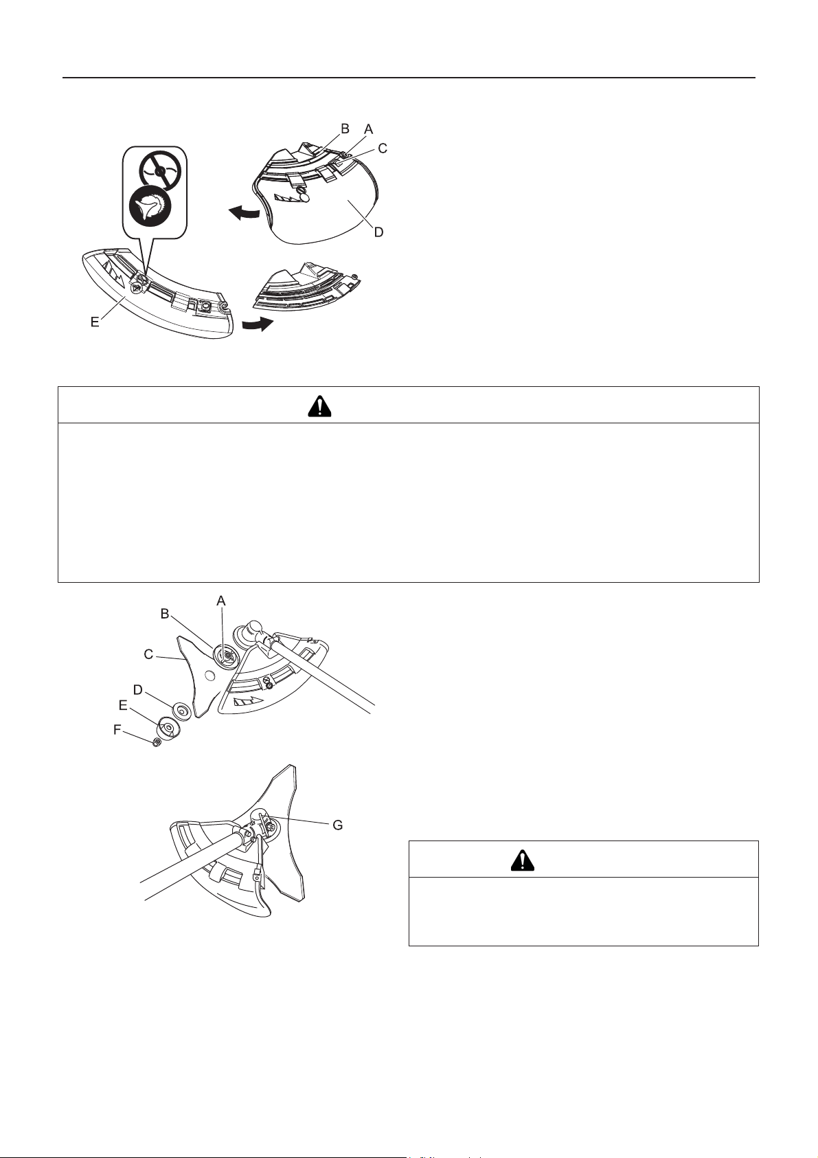
Entretien
Méthode de remplacement du protecteur d'outil
Il existe deux types de protecteurs d'outil : le premier est utili-
sé exclusivement pour les têtes de coupe à fil nylon et le second uniquement pour les lames métalliques. Lorsqu'une
lame métallique est utilisée, installer le protecteur d'outil pour
lames métalliques.
1. Dévisser entièrement le boulon (A) situé sur le côté droit du
support (B) pour faire glisser le protecteur. Le boulon ne
s'enlève pas et reste solidaire du support.
2. Tout en appuyant sur le bouton (C), faire glisser le protecteur
(D) vers la gauche et le retirer.
3. Placer le protecteur d'outil de remplacement (E) dans la rainure et le faire glisser vers la droite jusqu'en butée. Veiller à
serrer le boulon.
Pose de la lame (en option)
AVERTISSEMENT
Porter des gants résistants lorsque la lame doit être manipulée.
En cas de remplacement de la lame pendant une opération de taille, s'assurer que le moteur est coupé et que les
lames ne tournent plus.
En retournant l'appareil pour remplacer la lame, vérifier que le bouchon du réservoir de carburant est bien vissé.
Ne pas essayer de poser la lame d'une seule main ou sans utiliser la clé à pipe. Poser la lame avec précision à l'aide
de la clé à pipe fournie avec l'appareil et la serrer fermement.
Ne pas serrer la lame à l'aide d'outils autres que la clé à pipe fournie ; avec un outil pneumatique ou électrique, la
lame risquerait d'être serrée de manière excessive, ce qui casserait l'écrou ou l'arbre de sortie.
Si un écrou et une coupelle usés sont utilisés, la lame risque de se desserrer. Les remplacer par des pièces neuves.
Le non-respect de cette instruction peut entraîner un risque de blessure ou d'accident grave, ou encore d'incendie.
1. Examiner les lames (C) avant de les installer. Vérifier leur affûtage. Des lames émoussées augmentent le risque de rebonds. Des lames légèrement fissurées peuvent se fracturer
et des morceaux de lame peuvent être projetés pendant l'utilisation de l'appareil. Jeter les lames fissurées, quelle que
soit la taille de la fissure.
2. Bien serrer à la main le flasque (B), la lame, le flasque inférieur (D), la coupelle (E) et l'écrou (F).
3. Insérer l'outil de blocage (G) dans l'orifice situé sur le côté
droit du renvoi d'angle tout en poussant le ressort de retenue
vers la gauche.
4. Enfoncer l'outil de blocage dans le trou de blocage de
flasque (A) pour fixer l'arbre de sortie.
ATTENTION
Fixer solidement l'arbre de sortie à l'aide de l'outil de
blocage pour éviter qu'il ne tourne lors d e la pose d e la
lame. Sinon, l'écrou de fixation de la lame ne sera pas
suffisamment serré.
24
Page 59

Vérification de la lame
Entretien
5. Serrer l'écrou (en tournant dans le sens inverse des aiguilles
d'une montre) à l'aide d'une clé à pipe (H). Ne jamais serrer
l'écrou en utilisant le poids de votre corps. Dans le cas
contraire, le filetage de l'écrou risque de se briser.
Utiliser uniquement une lame recommandée pour ce modèle
par le constructeur.
En cas de fissure, remplacer la lame.
Vérifier que la lame est correctement fixée, conformément aux
instructions.
Vérification de la tête de coupe à fil nylon
Lorsque la lame commence à s'émousser, il est possible de
continuer à l'utiliser en la retournant.
En cas de fêlure ou de déformation de la lame, les vibrations
émises par l'appareil augmentent.
Procéder au remplacement de la lame.
Lors de l'affûtage de la lame, veiller à ce que les 3 tranchants
soient uniformément affûtés en utilisant une lime plate,
comme indiqué sur l'image. Dans le cas contraire, l'appareil
risque d'être déséquilibré et d'émettre plus de vibrations.
1. S'assurer que le pourtour des 2 ergots de fixation du boîtier
corresponde parfaitement au pourtour des ouvertures correspondantes du couvercle.
2. Vérifier que la tête de coupe est bien fixée sur le coupeherbe et la resserrer le cas échéant.
3. Contrôler la tête de coupe et rechercher toute déformation
ou bruit anormal en la faisant tourner manuellement. Une
déformation ou un bruit anormal peut provoquer des vibrations anormales ou entraîner le desserrage du coupe-herbe
pendant la rotation, ce qui constitue un risque.
4. Vérifier le degré d'usure du couvercle et de la partie inférieure de la bobine. Si une fente apparaît au bas de la partie
inférieure de la bobine ou au bas du couvercle, à proximité
de la sortie du fil nylon, il faut impérativement remplacer ces
pièces.
5. Vérifier si la tête de coupe présente des fissures ou des
éclats. Remplacer impérativement toute pièce présentant
une fissure ou un éclat.
25
Page 60

Entretien
Remplacement du fil nylon
DANGER
Toujours couper le moteur du coupe-herbe et s'assurer que la tête de coupe à fil nylon ne tourne plus avant de procéder au remplacement de la pièce.
Le non-respect de cette règle de sécurité entraîne un risque d'accident ou de blessure grave.
AVERTISSEMENT
Utiliser uniquement un fil de coupe flexible et non métallique recommandé par YAMABIKO CORPORATION.
Le non-respect de cette règle de sécurité entraîne un risque d'accident ou de blessure grave.
1. Comprimer les « ergots de fixation » (en deux endroits) vers
l'intérieur, puis retirer le couvercle. Il est plus facile de les retirer l'un après l'autre.
2. Déposer la bobine.
3. Lorsqu'il n'y a presque plus de fil nylon sur la bobine, retirer
le fil restant de la bobine et enrouler le « nouveau fil » en suivant les instructions (4) et suivantes. Lorsque le fil est
« collé » sur la bobine, retirer complètement le fil en décollant la partie « collée », puis enrouler le fil ainsi « décollé »
en suivant les instructions (4) et suivantes.
4. Plier le fil à 12 cm du milieu de sa longueur totale et accrocher la partie pliée sur l'« encoche » du séparateur intermédiaire.
5. Enrouler le fil bien tendu dans la rainure de la bobine en suivant « le sens d'enroulement de la flèche ».
6. Lorsque le fil est entièrement enroulé autour de la bobine,
accrocher ses deux extrémités dans les encoches correspondantes de la bobine pour le bloquer provisoirement ; laisser environ 10 cm de fil dépasser des encoches.
7. Aligner les encoches de la bobine avec les rainures des œillets, puis emboîter la bobine dans le couvercle.
8. Tirer le fil pour le faire dépasser du couvercle. (A) Retirer le
fil des « encoches correspondantes de la bobine », puis (B)
le faire passer dans les « rainures des œillets correspondants ».
26
Page 61

Entretien
9. Assembler le couvercle et le boîtier. (C) Aligner les
« œillets» du couvercle avec les « renfoncements » du boitier, puis (D) enfoncer les ergots du boîtier dans les ouvertures correspondantes du couvercle jusqu'à ce que les
ergots s'encastrent parfaitement.
DANGER
S'assurer que le pourtour extérieur des ergots du boîtier
corresponde parfaitement au pourtour extér ieur des ouvertures correspondantes du couvercle. Si les ergots sont
mal emboîtés et que la tête de coupe pivote, le couvercle
ou des composants internes risquent d'être projetés, ce
qui représente un danger potentiel pour l' utilisateur.
27
Page 62

Entretien
Guide de dépannage
IMPORTANT
En ce qui concerne les pièces de rechange et les consommables, utiliser uniquement des pièces d'origine et les produits et
les composants recommandés.
L'utilisation de pièces d'autres marques ou de composants inappropriés peut entraîner un dysfonctionnement de l'appareil.
Problème Diagnostic Cause Solution
Le moteur ne démarre pas
Le moteur démarre
difficilement,
tourne de manière
irrégulière
Le carburant pénètre dans le
tuyau de trop plein
Aucun carburant ne pénètre
dans le tuyau de trop plein
1. Il n'y a pas de carburant dans le réservoir de carburant
2. L'interrupteur d'arrêt est en position Arrêt
3. Alimentation en carburant excessive
4. Dysfonctionnement électrique
5. Dysfonctionnement du carburateur ou
blocage interne
6. Dysfonctionnement interne du moteur
1. Dégradation du carburant
2. Problème de carburateur
1. Le filtre à carburant est colmaté
2. Le circuit d'alimentation est colmaté
3. Blocage de pièces internes du carburateur
1. Alimentation en carburant
2. Basculer en position
Marche
3. Démarrer le moteur
après révision
4. Consulter un revendeur
5. Consulter un revendeur
6. Consulter un revendeur
1. Remplacer le carburant
2. Consulter un revendeur
1. Nettoyer ou remplacer
2. Consulter un revendeur
3. Consulter un revendeur
La bougie d'allumage est encrassée ou humide
Le moteur démarre
mais impossible
d'accélérer
Le moteur s'arrête 1. Problème de réglage du carburateur
Le moteur ne s'arrête pas
L'outil de coupe
tourne alors que le
moteur est au ralenti
1. Dégradation du carburant
2. Ecartement incorrect des électrodes
3. Dépôts de calamine
4. Dysfonctionnement électrique
1. Filtre à air encrassé
2. Filtre à carburant encrassé
3. Passage de carburant obstrué
4. Problème de réglage du carburateur
5. Blocage de la sortie d'échappement ou
de l'échappement de silencieux
2. Dysfonctionnement électrique
1. Dysfonctionnement de l'interrupteur
d'arrêt
1. Problème de réglage du carburateur
2. Ressort d'embrayage endommagé
1. Remplacer
2. Remplacer
3. Remplacer
4. Consulter un revendeur
1. Nettoyer ou remplacer
2. Nettoyer ou remplacer
3. Consulter un revendeur
4. Régler
5. Nettoyer
1. Régler
2. Consulter un revendeur
1. Procéder à un arrêt
d'urgence et consulter
un revendeur
1. Régler
2. Consulter un revendeur
En cas de problème différent de ceux décrits dans le tableau ci-dessus, consulter un revendeur.
Contacter un revendeur pour la mise au rebut de l'appareil ou de ses composants conformément à la législation nationale en
vigueur.
28
Page 63
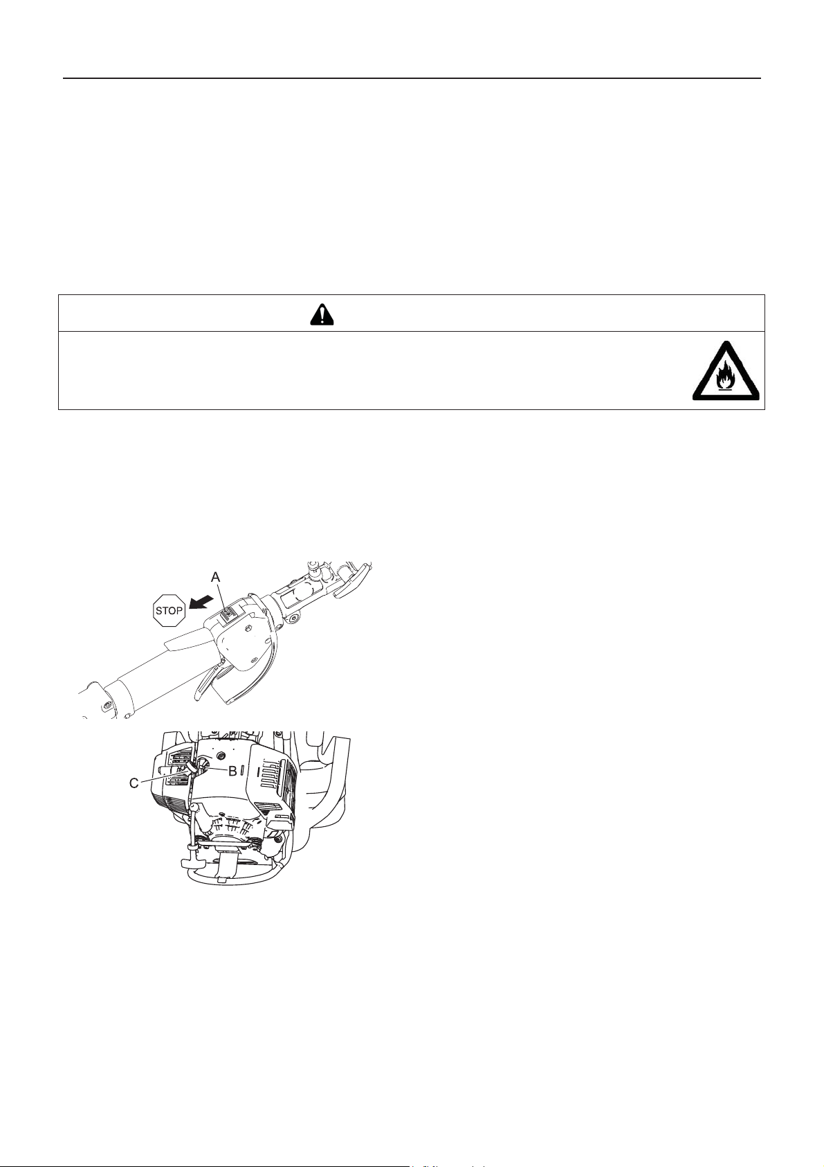
Entretien
Fabricant :
YAMABIKO CORPORATION
7-2 SUEHIROCHO 1-CHOME, OHME, TOKYO 198-8760, JAPON
Représentant autorisé en Europe :
Atlantic Bridge Limited
Atlantic House, PO Box 4800, Earley, Reading RG5 4GB, Royaume-Uni
Remisage
Remisage de longue durée (30 jours ou plus)
AVERTISSEMENT
Ne pas entreposer l'appareil dans un endroit clos contenant des vapeurs de carburant, ou à proximité
de sources de flammes ou d'étincelles.
Il existe un risque d'incendie.
Si l'appareil doit être remisé pendant une longue période (30 jours ou plus), respecter les instructions de remisage suivantes.
1. Vider le réservoir de carburant.
2. Comprimer et relâcher la pompe d'amorçage à plusieurs reprises pour évacuer le carburant présent dans la pompe
d'amorçage.
3. Démarrer le moteur et le laisser tourner au régime de ralenti
jusqu'à ce qu'il s'arrête de lui-même.
4. Placer l'interrupteur marche/arrêt (A) en position Arrêt
(Stop).
5. Une fois l'appareil suffisamment froid, nettoyer toute trace
de graisse, d'huile, de poussière, d'impureté et toutes les
autres substances présentes sur le coupe-herbe.
6. Effectuer les vérifications périodiques conseillées dans ce
manuel.
7. Vérifier que tous les écrous et vis sont serrés. Resserrer les
écrous et les vis desserrés.
8. Retirer la bougie d'allumage (B) et ajouter la quantité d'huile
appropriée (environ 10 ml) d'huile propre pour moteur à
2 temps dans le cylindre via la douille d'installation.
9. Placer un linge propre sur la douille d'installation de la bougie d'allumage.
10. Tirer 2 ou 3 fois la poignée du lanceur pour répartir l'huile
dans le cylindre.
11. Observer l'emplacement du piston à travers le trou de bougie. Tirer la poignée de lanceur à rappel automatique jusqu'à
ce que le piston atteigne le sommet de sa course et le laisser
dans cette position.
12. Installer la bougie d'allumage. (Ne pas connecter le protecteur de bougie (C).)
13. Placer l'étui protecteur de lame sur la lame et envelopper le
bloc moteur dans un sac en plastique ou autre. Entreposer
l'appareil dans un endroit sec, à l'abri de la poussière et hors
de portée des enfants.
29
Page 64

Caractéristiques
Caractéristiques
RM-520ES
Dimensions externes :
Longueur × Largeur × Hauteur 2828 × 449 × 564 mm
Masse :
Appareil sans carburant, outil de coupe ni protection (ISO11806)
Appareil avec outil de coupe spécifié, réservoir plein, protection et har-
nais
Volume : réservoir de carburant 1,0 L
Outil de coupe :
Tête de coupe à fil nylon
Largeur de tête de coupe à fil nylon (largeur de coupe)
Diamètre de la lame spécifiée (option)
Épaisseur de la lame spécifiée (option)
Nombre de dents de coupe (option)
Diamètre du trou central de la lame
Vitesse de rotation de la lame au régime moteur maximum autorisé
Rapport de vitesse : rapport de vitesse et lubrification Graisse longue durée, haute température et réduction
Sens de rotation de l'arbre de sortie vu du dessus : Sens inverse des aiguilles d'une montre
Moteur : type Monocylindre 2 temps à refroidissement pa r air
Cylindrée
Puissance maximum mesurée au frein selon la norme ISO 8893
Régime moteur à puissance maximale
Régime moteur maximum recommandé (avec outil standard monté)
Régime moteur de ralenti recommandé
Carburateur
Allumage
Bougie d'allumage
Lanceur
Embrayage
Carburant :
Huile
Mélange
12,0 kg
13,7 kg
Z5
430 mm
255 mm
3,0 mm
3
25,4 mm
10 000 tr/min
1,33
3
50,2 ml (cm
2,16 kW
9 000 min
10 900 min
2 800 min
)
-1
-1
-1
Type à membrane
Volant magnétique - système CDI
NGK BPMR8A
Lanceur à rappel automatique
Embrayage centrifuge automatique
Essence ordinaire. Il est conseillé d'utiliser de l'essence
sans plomb avec un indice d'octane 89 au minimum. Ne
pas utiliser de carburant contenant du méthanol ou plus
de 10 % d'éthanol.
Huile pour moteur 2 temps à refroidissement par air.
Norme ISO-L-EGD (ISO/CD 13738), norme JASO
FC,FD et huile ECHO Premium 50:1.
50:1 (2%)
Consommation de carburant à la puissance moteur maximale
Consommation spécifique de carburant à la puissance moteur maxi-
1,23 L/h
423 g/kW/h
male
Niveaux de vibrations : (ISO 22867) a
hv,eq
Poignée avant 5,3 m/s
Poignée arrière 4,0 m/s
Incertitude 1,2 m/s
Niveau de pression sonore : (ISO 22868) LpAeq 97,5 dB(A)
Incertitude 1,5 dB(A)
Niveau de puissance acoustique garanti : (ISO 22868) L
WA
114 dB(A)
Ces caractéristiques sont susceptibles d'être modifiées sans préavis.
30
2
2
2
Page 65

Le fabricant soussigné :
YAMABIKO CORPORATION
7-2 SUEHIROCHO 1-CHOME
OHME ; TOKYO 198-8760
JAPON
Cette déclaration de conformité est délivrée sous la seule responsabilité du fabricant.
déclare que l'appareil neuf désigné ci-après :
COUPE-HERBE/DÉBROUSSAILLEUSE
Marque : ECHO
Type : RM-520ES
est conforme aux :
* spécifications de la directive 2006/42/CE (utilisation de la norme harmonisée EN ISO 11806-2: 2011)
Déclaration de conformité
Déclaration de conformité
* spécifications de la directive 2004/108/CE (utilisation de la norme harmonisée EN ISO 14982: 2009)
* spécifications de la directive 2000/14/CE
Procédure d'évaluation de la conformité suivant l'ANNEXE V
Niveau de puissance sonore mesuré : 111 dB(A)
Niveau de puissance sonore garanti : 114 dB(A)
Numéro de série 37001001 et suivants
Tokyo, 1er octobre 2015
YAMABIKO CORPORATION
Représentant autorisé en Europe, autorisé à constituer le
dossier technique.
Société : Atlantic Bridge Limited
Adresse : Atlantic House, PO Box 4800, Earley, Reading RG5
4GB, Royaume-Uni
Masayuki Kimura M. Philip Wicks
Directeur général
Service Assurance qualité
31
Page 66

1Remarques et dos de couverture
7-2 SUEHIROCHO 1-CHOME, OHME, TOKYO 198-8760, JAPON
TÉLÉPHONE : 81-428-32-6118. FAX : 81-428-32-6145.
©
2015
X750-026430
X750222-7500
Imprimé au Japon
0x0xxxx zzzz ES
32
Page 67

1Schutzabdeckung
DEUTSCH
(Original Gebrauchsanleitung)
BEDIENUNGSANLEITUNG
RASENTRIMMER/MOTORSENSE
RM-520ES
WARNUNG
LESEN SIE DIE BEDIENUNGSANLEITUNG SORGFÄLTIG DURCH,
UND BEFOLGEN SIE DIE SICHERHEITSREGELN.
ANDERNFALLS BESTEHT DAS RISIKO SCHWERER
VERLETZUNGEN.
Page 68

Inhalt
Sichere Verwendung des Produkts ....................................................................................3
Beschreibung......................................................................................................................8
Bevor Sie beginnen ............................................................................................................9
Bedienung des Motors......................................................................................................13
Trimmen............................................................................................................................15
Wartung und Pflege..........................................................................................................20
Technische Daten.............................................................................................................29
Konformitätserklärung.......................................................................................................30
Gewährleistungs- und Garantiebestimmungen für ECHO- Motorgeräte ..........................31
Packliste ........................................................................................................................9
Zusammenbau.............................................................................................................10
Bereitstellen des Kraftstoffs.........................................................................................12
Starten des Motors ......................................................................................................13
Stoppen des Motors ....................................................................................................14
Einfaches Trimmen mit dem Nylonfadenkopf..............................................................16
Einfaches Trimmen mit Metallmesser..........................................................................19
Wartungsrichtlinien......................................................................................................20
Wartung und Pflege.....................................................................................................20
LAGERUNG.................................................................................................................28
2
Page 69

Sichere Verwendung des Produkts
Sichere Verwendung des Prod uk ts
Wichtige Informationen
WARNUNG
Lesen Sie unbedingt die Bedienungsanleitung, bevor Sie das Produkt verwenden.
Allgemeines zu dieser Bedienungsanleitung
Diese Bedienungsanleitung enthält wichtige Informationen über Montage, Bedienung und Instandhaltung Ihres
Produkts. Bitte lesen Sie sie sorgfältig durch, und machen Sie sich mit dem Inhalt vertraut.
Bewahren Sie die Anleitung stets an einem schnell zugänglichen Ort auf.
Sollte die Anleitung verloren gehen oder aufgrund von Beschädigungen nicht mehr lesbar sein, besorgen Sie sich
bitte eine neue Anleitung von Ihrem Händler.
Die in dieser Anleitung verwendeten Einheiten sind SI-Einheiten (Système International d'unités; Internationales
Einheitensystem). Zahlenangaben in Klammern sind Referenzwerte, bei denen mitunter geringe Umrechnungsfehler
vorliegen können.
Andernfalls kann es zu Unfällen bzw. schweren Verletzungen kommen.
Beabsichtigter Zweck dieses Produkts
Dieses Produkt ist ein mit Benzinmotor ausgerüstetes Hochleistungsgerät geringen Gewichts, das sich zur
Unkrautbekämpfung sowie zum Grasmähen und für leichte Freischneidearbeiten an Stellen eignet, wo andere
Methoden unzulänglich sind.
Verwenden Sie das Gerät nur für den oben angegebenen Zweck.
Um Weiterentwicklungen des Produkts Rechnung zu tragen, bleiben dem Hersteller Änderungen am Inhal t d ieser
Anleitung vorbehalten. Einige Abbildungen in dieser Anleitung können vom Produkt abweichen, um Sachverhalte
klarer darzustellen.
Bei Unklarheiten oder Problemen wenden Sie sich bitte an Ihren Händler.
Andernfalls kann es zu Unfällen bzw. schweren Verletzungen kommen.
Keine Veränderungen am Produkt vornehmen
An dem Produkt dürfen keine Veränderungen vorgenommen werden.
Andernfalls kann es zu Unfällen bzw. schweren Verletzungen kommen. Funktionsfehler, die auf Veränderungen am Produkt
zurückzuführen sind, fallen nicht unter die Herstellergarantie.
Produkt nur verwenden, wenn es überprüft und gewartet wurde
Das Produkt darf nur verwendet werden, wenn es überprüft u nd gewartet wurde. Die Überprüfung un d Wartung des
Produkts muss regelmäßig durchgeführt werden.
Andernfalls kann es zu Unfällen bzw. schweren Verletzungen kommen.
Verleihen oder Übereignen des Produkts
Wenn Sie das Produkt verleihen, muss die ausleihende Person auch die zugehörige Bedienungsanleitung erhalten.
Wenn Sie das Produkt einer anderen Person übereignen, muss die Bedienungsanleitung zusammen mit dem
Produkt ausgehändigt werden.
Andernfalls kann es zu Unfällen bzw. schweren Verletzungen kommen.
Benutzer des Geräts
Das Gerät darf von folgenden Personen nicht verwendet werden:
übermüdeten Personen
alkoholisierten Personen
unter Medikamenteneinfluss stehen de n Pe rs onen
schwangeren Frauen
Personen in schlechter körperlicher Verfassung
Personen, die die Bedienungsanleit ung nicht gelesen haben
Kindern
Seien Sie sich bewusst, dass der Benutzer für Unfälle bzw. Gefährdungen anderer Personen oder deren Eigentum
verantwortlich ist.
Eine Nichtbefolgung dieser Anweisungen kann zu Unfällen führen.
Von der Zündanlage dieses Geräts werden bei Betrieb elektromagnetische Felder erzeugt. Magnetfelder können
Störungen oder Ausfälle bei Herzschrittmachern verursachen. Um Gesundheitsrisiken zu reduzieren, empfehlen wir,
dass Personen mit Herzschrittmachern vor Betrieb dieses Geräts ihren Arzt und den Hersteller des
Herzschrittmachers konsultieren.
3
Page 70

Sichere Verwendung des Produkts
WARNUNG
Vibration und Kälte
Es wird vermutet, dass das Raynaud-Syndrom, das die Finger mancher Menschen befällt, durch stark vibrierende
Arbeitsgeräte und Arbeiten bei Kälte herbeigeführt wird. Durch stark vibrierende Arbeitsgeräte und dem Arbeiten bei
Kälte kann sich ein Prickeln und Brennen bemerkbar machen, dem sich Farblosigkeit und Gefühllosigkeit der Finger
anschließen. Die nachstehend aufgeführten Vorsichtsmaßnahmen werden dringend empfohlen, da die
Mindestwerte, bei denen diese Krankheit ausgelöst wird, nicht bekannt sind.
Halten Sie Ihren Körper warm, insbesondere Kopf und Nacken, Füße und Fußgelenke sowie Hände und
Handgelenke.
Legen Sie häufige Pausen ein, in deren Verlauf Sie den Kreislauf durch intensive Armübungen anregen, und
rauchen Sie nicht.
Begrenzen Sie die Dauerbetriebszeiten auf ein Minimum. Teilen Sie jeden Arbeitstag so ein, dass auch Arbeiten
ohne Trimmer oder tragbare motorisierte Geräte verrichtet werden.
Wenn Ihre Finger schmerzen, rot und angeschwollen sind und schließlic h b le ic h und gefühllos werden, müssen
Sie einen Arzt aufsuchen, bevor Sie sich weiter hi n Kälte und Vibrationen aussetzen.
Eine Nichtbefolgung dieser Anweisung kann zu gesundheitlichen Schäden führen.
RSI-Syndrom
Es wird angenommen, dass eine Überanstrengung der Muskel n und Sehnen der Finger, Hände, Arme und Sch ultern
in den betreffenden Körperteilen Schmerz, Schwellungen, Gefühllosigkeit, Schwäche und auch akuten Schmerz
verursachen kann. Durch bestimmte ständig wiederholte Handbewegungen steigt das Risiko für die Entwicklung
eines RSI-Syndroms. Auf folgende Art mindern Sie das Risiko des RSI-Syndroms:
Achten Sie darauf, dass Sie Ihr Handgelenk nicht zu sehr beugen, strecken od er verdrehen.
Legen Sie von Zeit zu Zeit Pausen ein, um wiederholte Bewegungen zu minimieren, und lassen Sie Ihre Hände
ruhen. Reduzieren Sie die Geschwindigkeit und den Kraftaufwand, mit denen Sie die Wiederholungsbewegung
ausführen.
Führen Sie geeignete Übungen zur Stärkung der Hand- und Armmuskulatur durch.
Suchen Sie einen Arzt auf, wenn Sie ein Prickeln, Gefü hllosigkeit oder Schmerzen in Ihren Fingern, Händen,
Handgelenken oder Armen bemerken. Je früher das RSI-Syndrom erkannt wird, desto eher lässt sich eine
dauerhafte Schädigung von Nerven und Muskeln verhindern.
Eine Nichtbefolgung dieser Anweisung kann zu gesundheitlichen Schäden führen.
Angemessene Unterweisung
Das Gerät darf nicht ohne angemessene Unterweisung bzw. ohne Schutzkleidung bedient werden.
Machen Sie sich mit der richtigen Handhabung des Geräts und seiner Bedienungselemente vertraut.
Sie müssen wissen, wie sich das Gerät stoppen und der Motor abstellen lässt.
Zudem müssen Sie lernen, wie das Gerät schnell vom Schultergurt getrennt werden kann.
Erlauben Sie niemals einer anderen Person, das Gerät ohne vorherige Unterweisung zu benutzen.
Eine Nichtbefolgung dieser Anweisung kann zu gesundheitlichen Schäden führen.
Geeignete Schutzkleidung tragen.
Ihr Haar sollte maximal Schulterlang sein, ansonsten verwenden Sie ein Haarnetz.
Tragen Sie keine Krawatten, Schmuckstücke oder lose, weite Kleidungsstücke, die sich
im Gerät verfangen könnten.
Tragen Sie keine Schuhe mit freien Zehen, und arbeiten Sie nicht barfuß oder in kurzen
Hosen.
Bei Nichtbeachtung dieser Sicherheitsvorkehrungen sind Ihr Augenlicht und Ihr Gehör
gefährdet, und es drohen sonstige schwere Verletzungen.
4
Page 71

Sichere Verwendung des Produkts
WARNUNG
Schutzausrüstung tragen
Tragen Sie beim Arbeiten mit dem Trimmer immer die folgende
Schutzausrüstung:
1. Kopfschutz (Helm): schützt den Kopf
2. Gehörschutzbügel oder Ohrenstöpsel: schützen das Gehör
3. Schutzbrille: schützt die Augen
4. Gesichtsschutzschild: schützt das Gesicht
5. Sicherheitshandschuhe: schützen die Hände vor Kälte und Vibration
6. Eng anliegende Arbeitskleidung (lang e Ärmel, lange Hosen): schützt den
Körper
7. Robuste, rutschfeste Stiefel (mit Schutzkappe) oder rutschfeste Schuhe (mit
Schutzkappe): schützen die Füße
8. Schienbeinschützer: schützen die Beine
Bei Nichtbeachtung dieser Sicherheitsvorkehrungen sind Ihr Augenlicht und Ihr Gehör
gefährdet, und es drohen sonstige schwere Verletzungen.
Falls erforderlich, verwenden Sie auch folgende Schutzausrüstung:
Staubmaske: schützt das Atmungssystem
Bienennetz: schützt vor angreifenden Bienen
Arbeitsumgebung und Bedienung
Produkt nicht verwenden:
unter schlechten Wetterbedingungen.
an steilen Abhängen oder auf rutschigem Untergrund ohne ausreichenden Halt.
nachts oder bei schlechten Sichtverhältnissen.
Arbeiten Sie an leichten Hanglagen in horizontalen, bogenartigen Bewegungen.
Wenn Sie fallen oder ausrutschen oder das Gerät nicht mehr voll beherrschen, kann dies zu schweren Verletzungen führen.
Aus Gesundheits- und Sicherheitsgründen sollten Sie mit dem Gerät nur bei Lufttemperaturen von -5oC bis 40oC
arbeiten.
Eine Nichtbefolgung dieser Anweisung kann zu gesundheitlichen Schäden führen.
Vorsorge für den Fall von Verletzungen
Für den unwahrscheinlichen Fall, dass es dennoch zu Verletzungen
kommt, sollten Sie folgende Dinge vorbereitet haben:
Verbandskasten
Hand- und Wischtücher (um etwaige Blutungen zu stoppen)
Trillerpfeife oder Mobiltelefon (um Hilfe rufen zu können)
Wenn Sie weder erste Hilfe leisten noch Hilfe rufen können, kann sich die
Verletzung verschlimmern.
Bei Feuer oder Rauch steht Sicherheit an erster Stelle.
Wenn Flammen aus dem Bereich des Motors kommen oder Rauch aus einem anderen Teil als dem
Auspuff austritt, entfernen Sie sich zunächst von dem Produkt, um Ihre eigene körperliche Sicherheit
zu gewährleisten.
Werfen Sie mit einer Schaufel Sand oder ähnliches Material auf das Feuer, um eine Ausbreitung zu
verhindern, oder löschen Sie den Bra nd mit einem Feuerlöscher.
Eine Panikreaktion könnte zu einer Ausbreitung des Feuers oder anderen Schäden führen.
Warnhinweise
GEFAHR WARNUNG VORSICHT
Dieses Symbol in Verbindung mit
dem Wort „GEFAHR" macht auf
Handlungen oder Bedingungen
aufmerksam, die zu schweren
Verletzungen oder zum Tod von
Bediener und umstehenden
Personen führen.
Dieses Symbol in Verbindung mit
dem Wort „WARNUNG" macht auf
Handlungen oder Bedingungen
aufmerksam, die zu schweren
Verletzungen oder zum Tod von
Bediener und umstehenden
Personen führen können.
„VORSICHT" warnt vor einer
Gefahrensituation, in der es zu
leichten bis mäßigen Verletzungen
kommen kann.
5
Page 72

Sichere Verwendung des Produkts
Sonstige Kennzeichnungen
HINWEIS WICHTIG
Kreis mit umgekehrtem
Schrägstrich bedeutet,
dass das Dargestellte
unzulässig ist.
Symbole
Symbol Beschreibung des Symbols Symbol Beschreibung des Symbols
Hinweise dieser Art enthalten Tipps
zur Verwendung, Pflege und Wartung
des Produkts.
Umrahmter Text mit der Überschrift
„WICHTIG" enthält wichtige
Informationen zur Verwendung,
Überprüfung, Wartung und Lagerung
des in dieser Anleitung
beschriebenen Produkts.
Lesen Sie die
Bedienungsanleitung
sorgfältig durch
Augen-, Gehör- und
Kopfschutz tragen
Tragen Sie
Schutzhandschuhe und
Schutzschuhe
NOTAUS
Warnung!
Gegenstände werden
hochgeschleudert!
Maximale Drehzahl der Welle
der Schneidvorrichtung in
U/min
Passanten auf einen Abstand
von 15 m halten
Benzin- und Ölgemisch
Choke-Position bei Kaltstart
(Choke geschlossen)
Choke-Position bei Betrieb
(Choke geöffnet)
Achtung, Seitenschub!
Einsatz ohne Schutzschild
verboten
Verwendung von
Metallmessern verboten
Verwendung von
Nylonfadenköpfen verboten
Justieren des Vergasers
- Leerlaufdrehzahl
Alle 18 Betriebsstunden
schmieren
Rundgriff
Achtung, heiße Bereiche
6
Page 73

Sichere Verwendung des Produkts
Symbol Beschreibung des Symbols Symbol Beschreibung des Symbols
Nicht in Räumen mit
schlechter Belüftung
verwenden
Achtung, Brandgefahr Motorstart
Achtung, Stromschlag-Gefahr
-
Garantierter
Schallleistungspegel
Sicherheitsaufkleber
Die in dieser Anleitung beschriebenen Produkte sind mit dem unten dargestellten Sicherheitsaufkleber versehen. Machen Sie
sich die Bedeutung des Sicherheitsaufklebers bewusst, bevor Sie das Produkt verwenden.
Falls der Sicherheitsaufkleber aufgrund von Verschleiß oder Beschädigung nicht mehr lesbar ist oder sich abgelöst hat,
erwerben Sie bitte einen neuen Sicherheitsaufkleber von Ihrem Händler, und bringen Sie ihn an der nachstehend gezeigten
Stelle an. Der Sicherheitsaufkleber muss stets gut lesbar sein.
1. Sicherheitsaufkleber (Teilenummer 890617-43130)
7
Page 74

Beschreibung
Beschreibung
1. Schneidvorrichtung - Nylonfadenkopf zum Schneiden
von Gras und Unkraut.
2. Schutzschild - Schützt den Bediener vor Kontakt mit
dem Schneidkopf und weggeschleuderten Objekten.
3. Winkelgetriebe - Ermöglicht es, den Winkel der
Rotationsachse zu andern.
4. Antriebswellenrohr - Geräteteil, das als Gehäuse für
die Antriebswelle dient.
5. Vorderer Handgriff - Zur Schneidvorrichtung hin
angebrachter Handgriff.
6. Stoppschalter - Schiebeschalter, der oben am
Gehäuse des Gashebels montiert ist. Schalter für den
Betrieb nach oben auf „RUN", zum Stoppen des Motors
nach unten auf „STOP" stellen.
7. Gashebel - Regelt die Motordrehzahl und wird durch
den Bediener mit einem Finger betätigt.
8. Gashebelsperre - Dient zum Arretieren des Gashebels
im Leerlauf, bis Sie mit der rechten Hand den Griff ganz
umgriffen haben.
9. Hinterer Handgriff - Zum rückentragbaren
Antriebsgerät hin angebrachter Handgriff.
10. Flexible Wellenbaugruppe - Biegsames Rohr für die
Antriebswelle.
11. Werkzeugtasche - Abnehmbare Werkzeugtasche für
Werkzeuge und Zubehörteile.
12. Auspuffabdeckung - Dient zum Schutz vor
versehentlicher Berührung mit dem heißen
Schalldämpfer.
13. Zündkerze
14. Startergriff - Ziehen Sie an diesem Griff, um den Motor
zu starten.
15. Kraftstofftank - Enthält Kraftstoff und Kraftstofffilter.
16. Luftfilterabdeckung - Deckt den Luftfilter ab.
17. Kraftstofftankdeckel - Verschließt den Kraftstofftank.
8
Page 75

Bevor Sie beginnen
Packliste
Die nachfolgend aufgeführten Einzelteile sind in der Verpackung enthalten.
Überprüfen Sie nach dem Auspacken die Vollständigkeit des Inhalts.
Wenden Sie sich an Ihren Händler, wenn Teile fehlen oder beschädigt sind.
Motor
Bevor Sie beginnen
Antriebswelle
1. Motor
2. Gashebel
3. Arretierwerkzeug
4. Steckschlüssel
5. L-Schlüssel
6. Schutzbrille
7. Vorsichtshinweis
8. Kunststoffkappe
9. Vorderer Griff
10. Nylonfadenkopf
11. Gurt
12. Bedienungsanleitung
13. Schutzschild (für Nylonfadenkopf)
14. Schutzschild (für Metallmesser)
15. Flexible Wellenbaugruppe
16. Antriebswellenrohr
9
Page 76
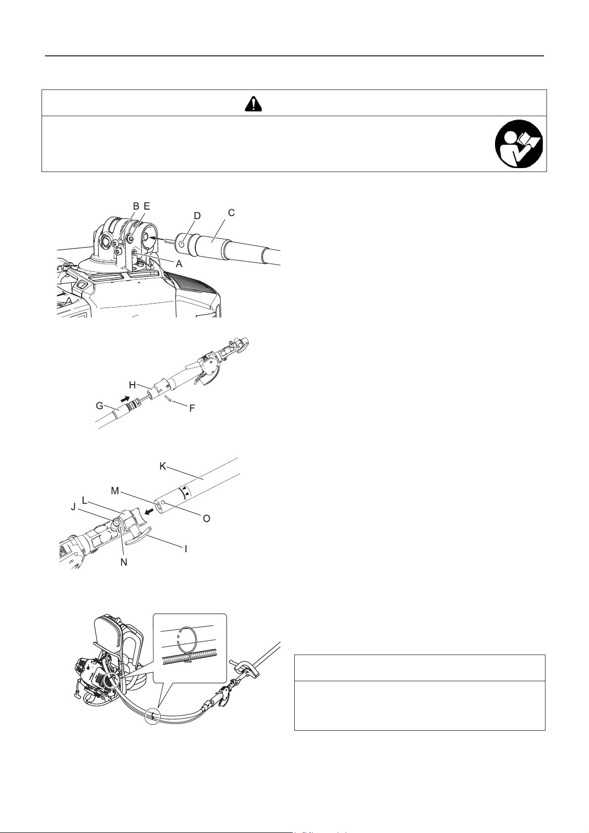
Bevor Sie beginnen
Zusammenbau
WARNUNG
Lesen Sie die Bedienungsanleitung aufmerksam durch, um sicherzustellen, dass Sie das Produkt
korrekt zusammenbauen.
Die Verwendung eines falsch zusammengebauten Produkts kann zu Unfällen bzw. schweren Verletzung en
führen.
Montage der Antriebswelle
1. Den Bolzen lösen (A).
2. Entfernen Sie den Verriegelungsbolzen (B).
3. Fügen Sie die flexible Wellenbaugruppe (C) in das
Winkelgetriebe ein.
4. Richten Sie die Öffnung der flexiblen Baugruppe (D) an der
Öffnung des Winkelgetriebes (E) aus.
5. Ziehen Sie Verriegelungsbolzen und Bolzen an.
6. Entfernen Sie den Verriegelungsbolzen (F).
7. Setzen Sie die flexible Wellenbaugruppe (G) in das
Hebelrohr ein.
8. Ziehen Sie den Verriegelungsbolzen fest.
9. Lösen Sie den Feststeller (I).
10. Ziehen Sie den Positionierstift (J) heraus, und drehen Sie ihn
zur Entriegelung um eine Viertelumdrehung nach links.
11. Fügen Sie die Antriebswelle (K) in das Verbindungselement
(L) ein, während Sie die Fassung (M) an der flexiblen Welle
(N) ausrichten.
12. Drehen Sie den Positionierstift um eine Vierteldrehung nach
rechts, bis er im Betriebsrohrloch einrastet. Achten Sie
darauf, dass der Positionierstift vollständig eingerastet ist,
indem Sie versuchen, die Antriebswelle zu drehen. Der
Positionierstift muss im Verbindungselement einschnappen
und darf nicht hervorstehen. Durch das vollständige
Einrasten wird vermieden, dass sich die Welle dreht.
13. Ziehen Sie den Verriegelungsbolzen fest.
14. Die zwei Klemmen an der flexiblen Wellenbaugruppe
müssen an geeigneten Stellen am Gaszug befestigt werden
(im gleichen Abstand über die Länge der flexiblen
Wellenbaugruppe).
HINWEIS
Zum Zerlegen die Schritte in umgekehrter Reihenfolge
durchführen. Setzen Sie die Kunststoffkappe am
Verbindungselement ein, um eine Fettundichtigkeit zu
vermeiden.
10
Page 77

Befestigung des Rundgriffs
Schultergurt
Bevor Sie beginnen
1. Befestigen Sie den vorderen Griff (A) und den Schutzhalter
(B) lose am Antriebswellenrohr (C).
2. Stellen Sie den vorderen Griff auf eine bequeme Position
ein.
3. Ziehen Sie die Schrauben (M5×35) (D) und Muttern (E) fest.
- Eine der 4 Schrauben muss wie abgebildet zusammen mit
der Hängescheibe (F) festgezogen werden.
1. Stellen Sie die Länge des Rückentragbands auf
komfortablen Sitz ein.
2. Da der Gurt (A) elastisch und einstellbar ist, sollte er an den
Hängescheiben (B) am vorderen Griff (C) und dem linken
oder rechten Rückentragband angeschlossen werden, um
einen ermüdungsfreien und komfortablen Betrieb zu
ermöglichen.
1. Vorderer Griff
2. Hängescheibe
3. Gurt
Montage des Schutzschilds
Montage des Nylonfadenkopfs
1. Befestigen Sie das Schutzschild (A) am Winkelgetriebe und
ziehen Sie die 4 Schrauben (B) fest.
VORSICHT
Verhindern Sie mit Hilfe des Arretierwerkzeugs ein
Mitdrehen des Werkzeugaufnahmebolzens, bevor Sie
den Fadenkopf montieren.
1. Stecken Sie das Arretierwerkzeug in das Loch auf der
rechten Seite des Winkelgetriebes. Drücken Sie dabei die
Rückhaltefeder nach links.
2. Stecken Sie das Arretierwerkzeug in das Arretierungsloch
(A) der Fixierplatte, um den Werkzeugaufnahmebolzen zu
blockieren.
3. Schrauben Sie den Nylonfadenkopf (B) (durch Drehen
gegen den Uhrzeigersinn) auf die Welle auf, und ziehen Sie
ihn gut fest.
4. Entfernen Sie das Arretierwerkzeug (C).
11
Page 78

Bevor Sie beginnen
Bereitstellen des Kraftstoffs
GEFAHR
Niemals betanken, während der Motor heiß ist oder läuft.
Beim Betanken auf keinen Fall rauchen oder Feuer in die Nähe bringen.
Andernfalls könnte sich der Kraftstoff entzünden und zu Verbrennungen führen.
WARNUNG
Befüllen Sie Kraftstofftanks niemals in geschlossenen Räumen. Befüllen Sie Kraftstofftanks immer im Freien und
auf sicherem Untergrund. Führen Sie die Betankung nicht auf der Ladefläche von Lkws oder an ähnlichen Orten
durch.
Kraftstofftanks und -kanister können unter Druck stehen. Öffnen Sie Kraftstofftankdeckel immer langsam, damit sich
der Druck ausgleichen kann.
Andernfalls kann es vorkommen, dass Kraftstoff herausspritzt.
Wischen Sie Kraftstoff, der aufgrund von Überfüllung über- oder ausläuft, sofort auf.
Verschütteter Kraftstoff kann sich entzünden und Verbrennungen verursachen.
Achten Sie nach dem Betanken stets darauf, dass aus der Kraftstoffleitung, an den Kraftstoffdichtungen und rund
um den Kraftstofftankdeckel kein Kraftstoff austritt. Sollten Sie feststellen, dass Kraftstoff austritt, stellen Sie sofort
die Verwendung des Produkts ein, und wenden Sie sich an Ihren Händler, um es reparieren zu lassen.
Ausgetretener Kraftstoff stellt in jedem Fall eine Brandgefahr dar.
Bewahren Sie den Befüllungskanister an einem scha ttigen Ort in weiter Entfernung von Brandquellen auf.
Verwenden Sie nur zugelassene Kraftstoffbehälter.
WICHTIG
Der Kraftstoff ist ein Gemisch aus Normalbenzin und hochwertigem Markenöl für luftgekühlte Zweitaktmotoren. Verwenden
Sie bleifreies Benzin mit mindestens 89 Oktan. Verwenden Sie keinen Kraftstoff mit Methyl alkohol oder mehr als 10 %
Ethylalkohol.
Gelagerter Kraftstoff altert. Mischen Sie nicht mehr Kraftstoff an, als Sie voraussichtlich innerhalb der nächsten dreißig
(30) Tage verbrauchen werden.
Kraftstoff
Empfohlenes Mischverhältnis: 50 : 1 (2%) Öl nach ISO-L-
EGD Standard (ISO/CD 13738), JASO FC, FD und ECHO
Premium 50: 1-Öl.
Mischen Sie den Kraftstoff nicht direkt im Motor-Kraftstofftank.
Kraftstoffversorgung
Befüllen Sie den Tank nicht bis zur Einfüllöffnung (A). Befüllen
Sie den Tank nur bis zur vorgeschriebenen Höhe (nur bis zum
Ansatz (B) des Einfüllstutzens).
Verschließen Sie den Kraftstofftankdeckel nach dem
Betanken wieder fest.
12
Page 79

Bedienung des Motors
Bedienung des Motors
Starten des Motors
WARNUNG
Befolgen Sie beim Starten des Motors unbedingt die folgenden Sicherheitsregeln:
Entfernen Sie sich mindestens 3 m von der Stelle, an der die Betankung erfolgte.
Platzieren Sie das Produkt an einem ebenen, gut belüfteten Ort.
Vergewissern Sie sich, dass nirgendwo Kraftstoff austritt.
Überprüfen Sie Metallmesser auf Bruchstellen.
Überprüfen Sie, ob alle Schrauben und Muttern fest angezogen sind.
Sorgen Sie für ausreichenden Abstand rund um das Produkt, und lassen Sie keine Personen oder Tiere in die Nähe.
Starten Sie den Motor mit dem Gashebel in der Leerlaufstellung.
Halten Sie das Produkt beim Starten des Motors auf dem Boden fest.
Eine Nichtbefolgung der Sicherheitsregeln kann zu Unfällen, Verletzungen oder sogar zum Tod führen.
Vergewissern Sie sich, dass nach dem Starten des Motors keine ungewöhnlichen Vibrationen oder Geräusche
wahrzunehmen sind. Verwenden Sie das Produkt nicht, wenn Sie ungewöhnliche Vibrationen oder Geräusche
feststellen. Wenden Sie sich an Ihren Händler, um es reparieren zu lassen.
Durch abfallende oder absplitternde Teile kann es zu schweren Verletzungen kommen.
Die Auspuffgase des Motors enthalten giftige Gase. Betreiben Sie das Produkt nicht in geschlossenen
Räumen oder an anderen schlecht belüfteten Orten.
Die Auspuffgase können zu Vergiftungen führen.
Schalldämpfer, Zündkerze, Winkelgetriebe und andere stark erhitzte Teile des Produkts dürfen während
des Betriebs und einige Zeit danach nicht berührt werden.
Berührungen solcher stark erhitzter Teile können zu Verbrennungen führen.
Zündkerze, Zündkabel und andere spannungsführende Teile dürfen während des Betriebs nicht
berührt werden.
Sie könnten einen Stromschlag erleiden, wenn Sie während des Betriebs ein spannungsfüh rendes Teil
berühren.
Wenn sich die Schneidvorrichtung beim Starten dreht, obwohl der Gashebel auf Leerlaufdrehzahl eingestellt ist,
justieren Sie den Vergaser nach, bevor Sie das Produkt verwenden.
Eine Nichtbefolgung der Sicherheitsregeln kann zu Unfällen, Verletzungen oder sogar zum Tod führen.
HINWEIS
Ziehen Sie den Startergriff zuerst langsam und dann allmählich schneller heraus. Ziehen Sie das Starterseil höchstens auf 2/
3 seiner Länge heraus.
Lassen Sie den Startergriff beim Zurückschnellen nicht los.
Starten eines kalten Motors
(Stecken Sie den Zündkerzenstecker wieder auf, wenn das
Produkt lange Zeit nicht benutzt wurde.)
1. Entfernen Sie die Messerabdeckung.
2. Legen Sie das Produkt flach auf den Boden, und sorgen Sie
durch Unterlegen eines Balkens oder eines ähnlichen
Hilfsmittels dafür, dass die Schneidvorrichtung nicht den
Boden berührt.
3. Stellen Sie den Zündschalter (A) auf „Start".
4. Stellen Sie sicher, dass sich der Gashebel (D) in der
Leerlaufstellung befindet.
13
Page 80

Bedienung des Motors
5. Stellen Sie den Chokehebel (F) auf die Position „Kaltstart"
(E).
6. Betätigen Sie die Kraftstoffpumpe (H) so oft (drücken und
loslassen), bis sie Kraftstoff angesaugt hat.
7. Halten Sie das Gerät möglichst nahe am Motor (siehe
Abbildung), nachdem Sie die Sicherheit des Ortes überprüft
haben, und ziehen Sie mehrmals am Startergriff (I).
8. Falls Sie ein explosionsartiges Geräusch hören und der
Motor sofort stillsteht, stellen Sie den Chokehebel auf „Run"
(Betrieb) (G), und ziehen Sie wiederholt am Startergriff, um
den Motor zu starten.
9. Falls der Motor weiterläuft, stellen Sie den Chokehebel
langsam zurück auf "Run".
10. Lassen Sie den Motor eine Weile im Leerlauf warmlaufen.
Starten eines warmen Motors
Stoppen des Motors
1. Stellen Sie den Zündschalter (A) auf „Start".
2. Stellen Sie sicher, dass sich der Gashebel (D) in der
Leerlaufstellung befindet.
3. Stellen Sie sicher, dass sich der Chokehebel in der Position
„Run" (Betrieb) befindet.
4. Ist kein Kraftstoff in der Kraftstoffpumpe sichtbar, betätigen
Sie die Kraftstoffpumpe so oft (drücken und loslassen), bis
sie Kraftstoff angesaugt hat.
5. Halten Sie das Gerät möglichst nahe am Motor, nachdem
Sie Ihre unmittelbare Umgebung auf Sicherheit überprüft
haben, und ziehen Sie am Startergriff, um den Motor zu
starten.
1. Stellen Sie den Gashebel (B) in die Leerlaufposition, und
lassen Sie den Motor bei Leerlaufdrehzahl (niedrige
Drehzahl) laufen.
2. Stellen Sie den Zündschalter (A) auf „Stop".
3. Stoppen Sie den Motor im Notfall sofort mit Hilfe des
Zündschalters.
4. Falls der Motor dadurch nicht gestoppt wird, bringen Sie den
Chokehebel in die Position „Kaltstart". Der Motor wird
„abgewürgt" und dadurch angehalten (Not-Aus).
Lassen Sie den Zündschalter von Ihrem Händler überprüfen
und reparieren, bevor Sie das Produkt erneut verwenden,
wenn sich der Motor mit dem Stoppschalter nicht stoppen
lässt.
5. Trennen Sie stets das Zündkabel von der Zündkerze, damit
der Motor nicht von Unbefugten gestartet werden kann,
wenn Sie mit der Arbeit fertig sind oder das Gerät
vorübergehend beiseite legen wollen.
14
Page 81

Trimmen
Trimmen
GEFAHR
Stellen Sie den Motor sofort ab, wenn die Schneidvor richtung blockiert wird.
Wenn die Blockade beseitigt wird und die Schneidvorrichtung plötzlich anläuft, kann es zu schweren Verletzungen kommen.
Verwenden Sie das Produkt niemals ohne den daran befestigten Schutzschild.
Von der Schneidvorrichtung abprallende Gegenstände können Unfälle mit schweren Verletzungen verursachen.
Der Bereich in einem Radius von 15 m rund um dieses Gerät gilt als
Gefahrenzone. Beachten Sie bei der Arbeit mit diesem Gerät folgende
Sicherheitsregeln:
Lassen Sie keine Personen (insbesondere Kinder) oder Tiere in die
Gefahrenzone.
Sollte eine Person in die Gefahrenzone gelangen, stellen Sie den
Motor ab, so dass sich die Schneidvorrichtung nicht mehr dreht.
Wenn Sie sich dem Bediener nähern möchten, signalisieren Sie ihm
Ihre Absicht, indem Sie z. B. Zweige von außerhalb der
Gefahrenzone werfen, und warten Sie dann, bis der Motor abgestellt
wurde und die Schneidvorrichtung stillsteht.
Wenn mehrere Personen mit dem Produkt arbeiten, vereinbaren Sie
eine Art der gegenseitigen Kommunikation, und arbeiten Sie mit
mindestens 15 m Abstand voneinander.
Von der Schneidvorrichtung abprallende Gegenstände und Kontakt mit der Schneidvorrichtung können zu Blindheit oder
tödlichen Unfällen führen.
WARNUNG
Bevor Sie mit der Arbeit beginnen, überprüfen Sie den Bereich, in dem Sie arbeiten möchten,
und entfernen Sie kleine Steine und leere Dosen, die durch die Schneidvorrichtung
weggeschleudert werden könn ten , sowie Schnüre oder Drähte, die sich um die
Schneidvorrichtung wickeln könnten.
Wenn Fremdkörper durch die Schneidvorrichtung weggeschleudert werden oder sich Drähte oder
andere Materialien um die Schneidvorrichtung wickeln, kann dies zu Unfällen bzw. schweren
Verletzungen führen.
Stellen Sie den Motor in den nachfolgend genannten Situationen sofort ab, und vergewissern Sie sich, dass sich die
Schneidvorrichtung nicht mehr dreht. Überprüfen Sie dann die einzelnen Bereiche des Produkts. Ersetzen Sie
beschädigte Teile durch neue.
Die Schneidvorrichtung trifft beim Arbeiten auf einen Stein, Baum, Pfosten oder ein anderes Hindernis.
Das Produkt beginnt plötzlic h, ungewöhnlich zu vibrieren.
Wenn beschädigte Teile weiter verwendet werden, kann dies zu Unfällen bzw. schweren Verletzungen führen.
Halten Sie die Schneidvorrichtung während des Arbeitens nicht nach oben. Die Schneidvorrichtung darf nicht über
Kniehöhe angehoben werden.
Durch Anheben der Schneidvorrichtung über Kniehöhe würden Sie die Rotationsebene näher ans Gesicht bringen, und
Gegenstände, die von der Schneidvorrichtung weggeschleudert werden, könnten Unfälle bzw. schwere Verletzungen
verursachen.
Transport des Geräts
Wenn Sie sich in den unten beschriebenen Situationen an eine andere Stelle bewegen, stellen Sie den Motor ab, und
warten Sie, bis sich das Trimmermesser nicht mehr dreht. Bringen Sie dann die Messerabdeckung an, und halten
Sie den Schalldämpfer von sich weg.
Sie suchen Ihren Arbeitsbereich auf
Sie wechseln im Verlauf der Arbeit den Arbeitsbereich
Sie verlassen Ihren bisherigen Arbeitsbereich
Bei Nichtbeachtung dieser Sicherheitsregeln können Verbrennungen oder andere schwere Verletzungen die Folge sein.
Zum Transport des Produkts in Kraftfahrzeugen entleeren Sie seinen Kraftstofftank, bringen Sie die
Messerabdeckung an, und sichern Sie das Produkt so, dass es nicht verrutschen kann.
Ein Transport des Produkts mit befülltem Kraftstofftank stellt eine Brandgefahr dar.
Versuchen Sie nie, das Produkt mit nur einer Hand zu bedienen.
Halten Sie die Griffe immer so, dass sie von Daumen und übrigen Fingern fest
umschlossen sind.
15
Page 82

Trimmen
1. Halten Sie den hinteren Griff des Antriebswellenrohrs in der
linken Hand, und hängen Sie sich das rechte
Rückentragband über die rechte Schulter.
2. Halten Sie den hinteren Griff des Antriebswellenrohrs in der
rechten Hand, und hängen Sie sich das linke
Rückentragband über die linke Schulter.
3. Bewegen Sie das Gerät ein paar Mal hin und her, um eine
gleichmäßige Belastung beider Schulterseiten zu erreichen.
4. Schließen Sie den Gurt vorzugsweise an den
Hängescheiben am Rundgriff am linken und rechten
Rückentragband an, und stellen Sie die Länge des Gurts auf
komfortablen Betrieb passend ein.
Erhöhen Sie nach Bedarf die Motordrehzahl; das Schneiden von
kräftigem Unkraut erfordert mehr Leistung als das Mähen von
Gras.
Halten Sie den vorderen Griff (Rundgriff) und den hinteren Griff
mit beiden Händen.
Beim Schneiden von Unkraut oder Gras schwingen Sie das
Messer in einem Bogen von einer Seite zur anderen und
gehen dabei vorwärts.
Das Messer dreht entgegen dem Uhrzeigersinn. Sie müssen
also die Pflanzen von rechts nach links scheiden.
So sollten Sie gehen: - Setzen Sie den rechten Fuß vor den
linken Fuß. - Schreiten Sie erst mit dem rechten Fuß vorwärts,
und achten Sie auf einen sicheren Stand. - Dann schreiten Sie
mit dem linken Fuß hinter den rechten.
Einfaches Trimmen mit dem Nylonfadenkopf
WARNUNG
Bei falscher Verwendung der Schneidvorrichtung drohen schwere Verletzungen. Lesen und befolgen Sie alle
Sicherheitsanweisungen in dieser Bedienungsanleitung.
Verwenden Sie nur von der YAMABIKO CORPORATION empfohlene Schneidvorrichtungen.
Nylonfäden, die über das Fadenschneidmesser hinausragen, könnten weggeschleudert werden, wenn sich de r
Fadenkopf nach der Anpassung der Nylonfadenlänge zu drehen beginnt.
Andernfalls kann es zu Unfällen bzw. schweren Verletzungen kommen.
Einstellen der Nylonfadenlänge
Verwenden Sie den Nylonfadenkopf nicht mit mehr als
10000 U/min.
Zum Nachstellen des Nylonfadens schlagen Sie den
Nylonfadenkopf bei unter 4500 U/min leicht gegen den Boden.
Das am Schutzschild montierte Fadenschneidmesser
begrenzt die Schnittbreite automatisch, indem es die
Nylonfäden auf die gleiche Länge abschneidet, nachdem der
Fadenkopf zu rotieren beginnt.
Wenn Sie mit einer geringeren Schnittbreite (weniger als max.
Länge) arbeiten möchten, schneiden Sie die beiden
Nylonfäden in gleicher Länge ab.
1. Auslöseknopf
2. Schlagen Sie den Auslöseknopf leicht gegen den Boden
3. Nylonfaden tritt aus
16
Page 83

Trimmen
Trimmen
Hierbei wird der Trimmer vorsichtig an das zu schneidende
Material herangeführt. Stellen Sie den Fadenkopf etwas
schräg, damit das Schneidgut von Ihnen weggeleitet wird.
Arbeiten Sie sich beim Schneiden in Richtung eines
Hindernisses (z. B. Zaun, Mauer oder Baum) in einem Winkel
vor, bei dem sichergestellt ist, dass vom Hindernis
abprallendes Schneidgut von Ihnen weggeleitet wird.
Bewegen Sie den Nylonfadenkopf langsam, bis das Gras bis
zum Hindernis abgemäht ist, dabei aber der Faden das
Hindernis nicht berührt. Wenn Sie Trimmarbeiten entlang
eines Maschendraht- oder Kettengliedzauns durchführen, so
achten Sie darauf, dass Sie das Gerät nur bis zum Zaundraht
führen. Ansonsten kann der Faden beim Auftreffen auf den
Zaundraht reißen.
Beim Trimmen können Unkrauthalme nacheinander
durchgeschnitten werden. Setzen Sie den Nylonfadenkopf
immer am unteren Bereich der Pflanze an, da sich die Pflanze
sonst evtl. nur beugt und wieder aufrichtet und sich im
Nylonfaden verfangen könnte. Anstatt das Unkraut sofort
durchzuschneiden, führen Sie das Ende des Nylonfadens
allmählich durch den Unkrauthalm.
1. Winkel zur Wand
2. Schneidgut
3. Schräg gestellte Schneidvorrichtung
4. Winkel zum Boden
Mähen
Skalpieren und Kantenschneiden
Hierbei werden große Grasflächen durch Schwingen des
Trimmers in einem horizontalen Bogen gemäht. Arbeiten Sie
in gleichmäßigen, ruhigen Bewegungen. Versuchen Sie nicht,
das Gras durch Hackbewegungen zu schneiden. Kippen Sie
den Nylonfadenkopf so, dass das gemähte Gras von Ihnen
weg auf die bereits gemähte Fläche geworfen wird. Dann –
ohne Gras zu schneiden – das Gerät zurückführen, um den
nächsten Bogen auszuführen. Wenn Sie gut geschützt sind
und es Ihnen nichts ausmacht, wenn Schneidgut auf Sie
zugeschleudert wird, können Sie in beide Richtungen mähen.
Beides wird durchgeführt, indem der Nylonfadenkopf steil
gekippt wird. Beim Skalpieren (A) wird die Vegetation so weit
geschnitten, dass nur der kahle Boden zurückbleibt. Beim
Kantenschneiden (B) wird das Gras an Stellen
zurückgetrimmt, an denen es über einen Fußgängerweg oder
eine Zufahrt gewachsen ist. Sowohl beim Kantenschneiden
als auch beim Skalpieren ist das Gerät in einem steilen Winkel
so zu halten, dass das Schneidgut sowie sich aus dem Boden
lösende Steine und Schmutz nicht auf Sie zugeschleudert
werden.
Wenngleich das Kantenschneiden und Skalpieren hier in einer
bestimmten Weise abgebildet sind, muss jeder Bediener für
sich selbst gemäß seiner Körpergröße den Winkel
herausfinden, in dem er besten arbeiten kann.
Bei fast allen Schneidarbeiten empfiehlt es sich, den
Nylonfadenkopf so schräg zu stellen, dass der Kontakt in dem
Teil des Schneidkreises erfolgt, wo der Nylonfaden sich von
Ihnen und dem Schutzschild wegbewegt (siehe Abbildung).
Dadurch wird das Schneidgut von Ihnen weggeleitet.
Wenn Sie den Fadenkopf zur falschen Seite neigen, wird das
Schneidgut auf Sie zugeschleudert. Wenn der
Nylonfadenkopf flach gegen den Boden gehalten wird, so
dass der Schneidvorgang über den gesamten Schneidkreis
erfolgt, wird das Schneidgut auf Sie zugeschleudert, die
Motordrehzahl durch den Widerstand verringert, und es wird
sehr viel mehr Nylonfaden verbraucht.
17
Page 84

Trimmen
Nylonfadenkopf dreht sich gegen den Uhrzeigersinn. Das
Fadenschneidmesser befindet sich links am Schutzschild.
1. Schneidgut
2. Auf dieser Seite schneiden
Lassen Sie den Nylonfadenkopf nicht in zähes Unkraut,
Bäume oder Zäune eindringen.
Wenn der Nylonfaden in Maschendraht, Zäune oder dichtes
Gestrüpp eindringt, kann es passieren, dass abgerissene
Fadenstücke gegen den Bediener geschleudert werden. Am
besten arbeiten Sie sich so weit wie möglich an das jeweilige
Hindernis heran, ohne den Nylonfaden in das Hindernis
vordringen zu lassen. Schneiden Sie nicht direkt an einem
Hindernis.
Achten Sie darauf, dass der Nylonfaden nicht mit
beschädigtem Zaundraht in Berührung kommt. Durch den
Trimmer abgebrochene Drahtstücke können mit hoher
Geschwindigkeit durch die Luft geschleudert werden.
18
Page 85

Trimmen
Einfaches Trimmen mit Metallmesser
WARNUNG
Befolgen Sie beim Trimmen die folgenden Anweisungen:
Vergewissern Sie sich, dass die Befestigungsmutter des Messers fest angezogen ist.
Wenn der Schutzschild beschädigt oder gerissen ist, ersetzen Sie ihn durch einen neuen.
Ersetzen Sie die Befestigungsmutter des Trimmermessers, wenn sie Verschleißspuren
aufweist.
Lassen Sie das Messer nicht den Erdboden berühren.
Arbeiten Sie nicht mit einem stumpfen, verbogenen, gebrochenen oder verfärbten Messer
und nicht mit einer verschlissenen oder beschädigten Befestigungsmutter.
Lassen Sie den Motor niemals ohne Last mit Vollgas laufen.
Andernfalls kann es zu Unfällen bzw. schweren Verletzungen kommen.
Verwenden Sie nur von der YAMABIKO CORPORATION empfohlene Schneidvorrichtungen.
Das Messer muss dem zu schneidenden Material entsprechen. Ein falsches oder stumpfes Messer ka nn zu
Verletzungen führen. Messer müssen scharf sein. Stumpfe Messer erhöhen die Gefahr eines Rückschlags und die
Verletzungsgefahr für sich selbst und andere Personen.
Plastik-/Nylonmesser für Gras und Unkraut können da eingesetzt werden, wo der Nylonfadenkopf zum Einsatz
kommt. Diese Messer nicht für Buschwerk oder dichtes Unkrau t verwenden.
Das 3-Zahn-Messer ist speziell zum Schneiden von Unkraut und Gras vorgesehen. Verwenden Sie das 3-ZahnMesser nicht zum Schneiden von Gestrupp oder Baumen, um Verletzungen aufgrund von Ruckschlag oder
Klingenbruch zu vermeiden.
Das 8-Zahn-Messer ist zum Schneiden von Gras, Gartenabfällen und Unkraut vorgesehen. Verwenden Sie dieses
Messer nicht für Buschwerk oder starke holzhaltige Vegetation mit einem Durchmesser von 19 mm oder mehr.
Das 22-Zahn-Messer ist für dichtes Strauchwerk und Trieblinge bis zu einem Durchmesser von 64 mm
vorgesehen.
Das 80-Zahn-Messer ist für das Schneiden von Gestrüpp und holzhaltiger Vegetation von bis zu 13 mm
Durchmesser vorgesehen.
Beschädigte oder gebrochene Messer können Unfälle bzw. schwere Verletzungen verursachen.
Rückschlag
Wenn das Trimmermesser bei hoher Drehzahl auf einen
Baum, Pfosten, Stein oder einen anderen Gegenstand trifft,
prallt es urplötzlich heftig zurück. Dieses Phänomen wird als
Rückschlag bezeichnet.
Ein solcher Rückschlag kann bewirken, dass der Bediener
die Kontrolle über das Produkt verliert, und ist deshalb
höchst gefährlich.
Insbesondere, wenn das vordere rechte Viertel des
Trimmermessers (B) auf einen Busch oder ein anderes
Objekt trifft, wird das Produkt heftig nach rechts
zurückgeschleudert.
Um solche Rückschläge zu vermeiden, sollten Sie niemals von links nach rechts trimmen. Achten Sie stets darauf,
dass das Trimmermesser nicht auf harte Gegenstände trifft.
Achten Sie beim Trimmen darauf, dass das zu beschneidende Objekt vom vorderen Drittel der linken Seite des
Messers erfasst wird (A).
Andernfalls kann es zu Unfällen bzw. tödlichen Verletzungen kommen.
Unkraut mähen
Beim Mähen wird die Schneidvorrichtung in einem
horizontalen Bogen geschwungen. Dadurch lassen sich große
Bereiche rasch von Gras und Unkraut befreien. Die
Sensenmethode eignet sich jedoch nicht zum Mähen von
hohem, zähem Unkraut oder holzhaltiger Vegetation.
Wenn sich im Messer ein Schößling oder eine Staude
verfängt, darf das Gerät nicht als Hebel benutzt werden, um
die Pflanze zu entfernen, da die Schneidvorrichtung dadurch
beschädigt werden würde.
Schalten Sie stattdessen den Motor ab, und entfernen Sie,
nachdem das Messer zum Stillstand gekommen ist, den
Schößling bzw. die Staude vom Messer.
19
Page 86

Wartung und Pflege
Wartung und Pflege
WARNUNG
Beachten Sie die folgenden Sicherheitsregeln, wenn Sie das Produkt nach der Verwendung überprüfen bzw. warten:
Schalten Sie den Motor ab und überprüfen bzw. warten Sie das Produkt erst dann, wenn der Motor abgekühlt ist.
Andernfalls können Sie sich verbrennen.
Entfernen Sie den Zündkerzenstecker, bev o r Sie Über prüfungen und Wartungen durchführen.
Wenn sich das Produkt unerwarteterweise in Betrieb setzt, kann es zu Unfällen kommen.
WICHTIG
Für Überprüfung und Wartung sind entsprechende Fachkenntnisse erforderlich. Wenn Sie das Produkt nicht selbst
überprüfen, warten oder instand setzen können, wenden Sie sich an Ihren Händler. Versuchen Sie nicht, das Gerät zu
zerlegen.
Wartungsrichtlinien
Komponente Wartung Seite Vor der Verwendung Monatlich
Luftfilter Reinigen / ersetzen 21 •
Kraftstofffilter Überprüfen / reinigen / ersetzen 21 •
Zündkerze Überprüfen / reinigen / justieren /
ersetzen
22 •
Vergaser Justieren / ersetzen und justieren 21 •
Kühlsystem Überprüfen / reinigen 22 •
Schalldämpfer Überprüfen/festziehen 22 •
Schalldämpfer Reinigen 22 •***
Flexible Welle Schmieren 23 •*
Winkelgetriebe Schmieren 23 •**
Anlasser Überprüfen - •
Fadenschneidmesser Überprüfen / reinigen - •
Kraftstoffsystem Überprüfen 21 •
Schrauben, Bolzen und
Muttern
* oder nach 18 Betriebsstunden (jeweils früherer Zeitpunkt gilt). ** Oder 50 Betriebsstunden (jeweils früherer Zeitpunkt gilt). ***
Oder 100 Betriebsstunden (jeweils früherer Zeitpunkt gilt).
Überprüfen, festziehen / ersetzen - •
WICHTIG
Angegeben sind die maximalen Zeitabstände. Die Häufigkeit der erforderlichen Wartungsarbeiten richtet sich nach der
tatsächlichen Beanspruchung und Ihrer Erfahrung.
Wartung und Pflege
Wenden Sie sich bei Fragen oder Problemen bitte an Ihren Händler.
20
Page 87

Reinigen des Luftfilters
Auswechseln des Kraftstofffilters
Wartung und Pflege
1. Schließen Sie den Choke. Lösen Sie die Schraube, und
entfernen Sie die Luftfilterabdeckung (A).
2. Entfernen Sie den Luftfilter (B) (befindet sich unter der
Luftfilterabdeckung).
3. Reinigen Sie den Filter durch Abbürsten oder mittels
Druckluft.
4. Setzen Sie den Filter wieder ein.
5. Setzen Sie die Abdeckung wieder auf, und ziehen Sie die
Schraube an.
1. Ziehen Sie den Kraftstofffilter mit Hilfe eines Metalldrahts o.
Ä. durch die Tanköffnung heraus.
2. Ziehen Sie den alten Filter von der Kraftstoffleitung (B) ab.
3. Installieren Sie den neuen Filter.
HINWEIS
Ersetzen Sie den Filter, wenn er stark verschmutzt oder
beschädigt ist.
Justieren des Vergasers
WARNUNG
SIE KÖNNEN DIE LEERLAUFDREHZAHL NUR EINSTELLEN, indem Sie die Leerlaufanschlagschraube (T) drehen.
Bei der Vergaserjustierung kann sich die Schneidvorri chtung bewegen. Achten Sie ganz besonders auf die
Schneidvorrichtung, um sich nicht durch das sich bewegende Schneidegerät zu verletzen.
Nach erfolgter Vergaserjustierung darf sich die Schneidvorrichtung nicht mit Leerlaufdrehzahl bewegen; ansonsten
besteht die Gefahr schwerer Verletzungen.
Außer der Drehzahl dürfen Sie KEINE weitere Vergaserjustierung vornehmen. Alle anderen Einstellungen MÜSSEN
von einem autorisierten Vertragshändler durchgeführt werden, andernfalls besteht die Gefahr schwerer
Verletzungen aufgrund einer Fehlfunktion des Motors.
VORSICHT
Wenden Sie sich bei Problemen mit dem Vergaser an einen autorisierten Vertragshändler.
Jedes Gerät wird werkseitig einem Probelauf unterzogen, bei
dem der Vergaser auf optimale Leistung eingestellt wird.
Reinigen/wechseln Sie vor der Vergaserjustierung den L uftfilter,
starten Sie den Motor, und lassen Sie ihn einige Minuten
warmlaufen.
So justieren Sie den Vergaser:
Drehen Sie die Leerlaufanschlagschraube (T) im
Uhrzeigersinn, bis die Schneidvorrichtung beginnt, sich zu
drehen. Drehen Sie anschließend die
Leerlaufanschlagschraube (T) entgegen dem Uhrzeigersinn
heraus, bis sich die Schneidvorrichtung nicht mehr dreht.
Drehen Sie die Leerlaufanschlagschraube (T) entgegen dem
Uhrzeigersinn heraus, und anschließend um eine zusätzliche
Umdrehung.
HINWEIS
Wenn der Vergaser mit der Leerlaufanschlagschraube (T)
nicht korrekt eingestellt werden kann, müssen Sie einen
autorisierten Vertragshändler kontaktieren.
21
Page 88
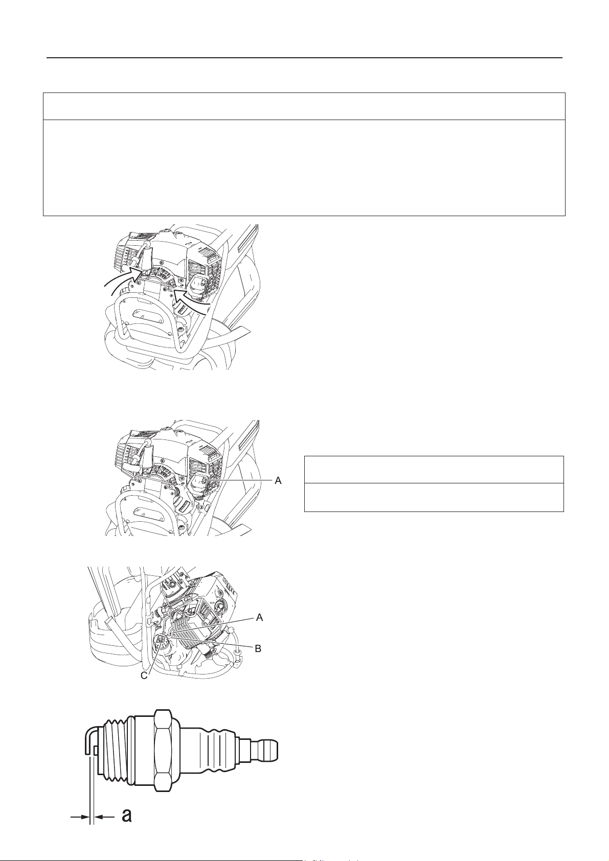
Wartung und Pflege
Wartung des Kühlsystems
WICHTIG
Um die richtige Motorbetriebstemperatur aufrechtzuerhalten, muss die Kühlluft ungehindert den
Zylinderrippenbereich durchströmen können. Durch diesen Luftstrom wird die Verbrennungswärme vom Motor
abgeführt. Unter folgenden Umständen kann es zu Überhitzung und Kolbenfr essern im Motor kommen:
Die Luftzufuhröffnungen sind verstopft. Dadurch gelangt keine Kühlluft zum Zylinder;
Staub und Gras haben sich außen am Zylinder angesammelt. Durch diese Ansammlung wird der Motor isoliert,
und die Wärme kann nicht mehr abgegeben werden.
Das Beheben von Verstopfungen von Kühlluft-Durchgängen bzw. die Reinigung der Zylinderrippen gelten als normale
Wartungsarbeiten. Störungen auf Grund mangelhafter Wartung und Pflege fallen nicht unter die Garantie.
Achten Sie darauf, dass Motor und Luftzufuhrgitter frei von
Schmutz sind.
Luftzufuhröffnung
Reinigen des Schalldämpfers
Überprüfen des Kraftstoffsystems
Kohlenstoffablagerungen im Schalldämpfer (A) verringern die
Motorleistung und führen zu Überhitzung. Ablagerungen vom
Schalldämpfer entfernen.
WICHTIG
Die Schalldämpferabdeckung nicht ausbauen. Fragen Sie bei
Bedarf bitte Ihren Händler um Rat.
Überprüfen Sie diesen Punkt vor jeder Verwendung.
Vergewissern Sie sich nach jeder Betankung, dass kein
Kraftstoff an den Leitungen (A), Dichtungen (B) oder am
Tankdeckel (C) austritt.
Wenn Kraftstoff oder Kraftstoffdämpfe austreten, besteht
Brandgefahr. Schalten Sie das Gerät in diesem Fall sofort aus,
und lassen Sie es von Ihrem Händler überprüfen bzw.
austauschen.
Überprüfen der Zündkerze
DPP
1. Prüfen Sie den Elektrodenabstand. Der korrekte Abstand
beträgt 0,6 bis 0,7 mm.
2. Prüfen Sie die Elektrode auf Verschleiß.
3. Prüfen Sie den Isolierkörper auf Öl- oder andere
Ablagerungen.
4. Wenn die Elektroden oder Kontakte verschlissen sind oder
die Keramikteile Risse aufweisen, ersetzen Sie sie durch
neue Teile.
5. Auf 15 N·m - 17 N·m (150 kgf·cm bis 170 kgf·cm) festziehen.
Die Funkenprüfung (zur Feststellung, ob die Zündkerze einen
22
Page 89

Schmieren der flexiblen Welle
Wartung und Pflege
Zündfunken wirft) muss von Ihrem Händler durchgeführt
werden.
Die gesamte Oberfläche der flexiblen Welle muss immer
ausreichend geschmiert sein.
Die flexible Welle ist ab Werk vorgeschmiert. Alle
18 Betriebsstunden muss deshalb ihre gesamte Oberfläche
mit ca. 10 ml Fett eingeschmiert werden.
1. Ziehen Sie die flexible Welle aus dem Winkelgetriebe
heraus.
2. Ziehen Sie die flexible Welle aus der Baugruppe, flexible
Welle heraus.
3. Verwenden Sie das gleiche Fett wie im Winkelgetriebe.
4. Beim Wiederzusammenbau ist es empfehlenswert, die
flexible Welle rückwärts einzusetzen. Der Anschlag (A)
muss an der Winkelgetriebeseite der flexiblen Welle
angebracht werden.
Winkelgetriebe
Wechseln des Schutzschildes
1. Bauen Sie den Stopfen (A) und die Ablassschraube (B) aus
dem Winkelgetriebe (C).
2. Füllen Sie das Getriebe mit so viel neuem Schmierfett, bis
das alte Schmierfett herausgedrückt wird. Verwenden Sie
bei Bedarf eine Niederdruckpumpe.
3. Bauen Sie die Ablassschraube und den Stopfen wieder ein.
1. Entfernen Sie den Stopfen (A) aus dem Winkelgetriebe (C).
2. Fügen Sie ggf. mit einer Fettpresse neues Fett hinzu.
WICHTIG
Verwenden Sie das echte Fett von YAMABIKO
CORPORATION (Teilenummer: X695-000010).
3. Setzen Sie den Stopfen wieder ein.
Es gibt zwei unterschiedliche Schutzschilde: der eine
Schutzschild wird ausschließlich zur Verwendung des
Nylonfadenkopfes, der andere ausschließlich zur
Verwendung von Metallmessern angebracht. Wenn Sie mit
Metallmessern arbeiten, verwenden Sie den Schutzschild für
Metallmesser.
1. Lösen Sie die Schraube (A) auf der rechten Seite der
Halterung (B) komplett, um das Schutzschild verschieben zu
können. Die Schraube selbst kann nicht von der Halterung
entfernt werden.
2. Drücken Sie die Taste (C), schieben Sie das Schutzschild
(D) nach links und nehmen es ab.
3. Ein anderes Schutzschild (E) in die Nut einführen und bis
zum Anschlag nach rechts schieben. Die Schraube
unbedingt festziehen.
23
Page 90

Wartung und Pflege
Montage des Messers (option)
WARNUNG
Tragen Sie beim Arbeiten mit dem Trimmermesser robuste Handschuhe.
Wenn während eines Trimmereinsatzes ein Trimmermesser ausgetauscht werden muss, vergewissern Sie sich,
dass der Motor zuvor ausgeschaltet wurde und das Messer zum Stillstand gekommen ist.
Achten Sie darauf, dass der Kraftstofftankdeckel fest verschlossen ist, wenn Sie das Produkt umdrehen, um das
Trimmermesser auszutauschen.
Versuchen Sie nicht, das Trimmermesser mit einer Hand oder ohne Verwendung des Steckschlüssels zu montieren.
Befestigen Sie das Trimmermesser ordnungsgemäß mit dem mitgelieferten Steckschlüssel, und ziehen Sie es in der
richtigen Position fest.
Verwenden Sie zum Festziehen der Schneidmesser ausschließlich den vorgeschriebenen Steckschlüssel. Die
Verwendung eines Druckluft- oder elektrisch betriebenen Geräts könnte dazu führen, dass das Schneidmesser
übermäßig fest angezogen wird und dass die Mutter oder der Werkzeugaufnahmebolzen brechen.
Bei Verwendung von verschlissenen Muttern und Auflagetellern zur Befestigung des Messers besteht die Gefahr,
dass sich das Messer lockert. Ersetzen Sie diese Teile durch neue.
Andernfalls kann es zu Unfällen, schweren Verletzungen oder Bränden kommen.
1. Kontrollieren Sie die Messer (C) vor der Montage.
Überprüfen Sie die Schärfe Bei stumpfen Messern erhöht
sich das Risiko eines Rückschlags. Kleine Risse können
sich zu Brüchen entwickeln, sodass Teile des Messers
während des Betriebs weggeschleudert werden. Entsorgen
Sie gerissene Messer, egal, wie klein der Riss ist.
2. Die obere Druckplatte (B), Messer, untere Druckplatte (D),
Auflageteller (E) und Mutter (F) handfest anziehen.
3. Stecken Sie das Arretierwerkzeug (G) in das Loch auf der
rechten Seite des Winkelgetriebes. Drücken Sie dabei die
Rückhaltefeder nach links.
4. Stecken Sie das Arretierwerkzeug in das Arretierungsloch
(A) der Fixierplatte, um den Werkzeugaufnahmebolzen zu
blockieren.
VORSICHT
Verhindern Sie mit Hilfe des Arretierwerkzeugs ein
Mitdrehen des Werkzeugaufnahmebolzens, bevor Sie
das Messer montieren. Andernfalls kann die Mutter zur
Befestigung des Messers nicht ausreichend
festgezogen werden.
5. Ziehen Sie die Mutter mit einem Steckschlüssel (H) fest
(gegen den Uhrzeigersinn). Niemals mit voller Kraft
anziehen. Das Gewinde der Mutter könnte beschädigt
werden.
24
Page 91

Überprüfen des Messers
Wartung und Pflege
Verwenden Sie nur Messer, die vom Hersteller für dieses
Modell vorgesehen sind.
Wenn das Messer einen Riss aufweist, ersetzen Sie es sofort
durch ein neues.
Achten Sie darauf, dass das Messer gemäß den Anweisungen
montiert wird.
Wenn das Messer stumpf wird, drehen Sie es um, und
benutzen Sie die scharfe Gegenseite.
Bei Zersplitterung oder Verformung gerät das Messer in
heftigere Vibration.
Ersetzen Sie sie es in diesem Fall sofort.
Schärfen Sie das 3-Zahn-Messer mit einer Flachfeile an jeder
Schneide gleichmäßig (siehe Abbildung). Anderenfalls
entsteht eine Unwucht und die Vibrationen werden verstärkt.
Überprüfen des Nylonfadenkopfs
Auswechseln des Nylonfadens
1. Vergewissern Sie sich, dass jeder der 2 Rückhaltestifte des
Gehäuses vollständig in die entsprechenden Aussparungen
eingerastet ist.
2. Überprüfen Sie die Montage des Fadenkopfs am Trimmer,
und ziehen Sie ihn fest, falls er lose ist.
3. Überprüfen Sie den Fadenkopf durch Drehen per Hand auf
unrunden Lauf und ungewöhnliche Geräusche. Bei
unrundem Lauf und ungewöhnlichen Geräuschen können
Vibrationen auftreten, die sich auf den Trimmer übertragen
können. Dadurch können sich Teile lösen und eine Gefahr
darstellen.
4. Überprüfen Sie die Abdeckung und den Auslöseknopf auf
Abnutzung. Wenn am unteren Bereich des Auslöseknopfs
oder in der Nähe des Nylonfadenaustritts ein Spalt zu sehen
ist, ersetzen Sie diese Teile umgehend durch neue.
5. Prüfen Sie den Fadenkopf auf Bruch oder Absplitterung.
Ersetzen Sie alle Teile, die gebrochen sind oder
Absplitterungen aufweisen, umgehend durch neue.
GEFAHR
Bevor Sie mit dem Auswechseln des Nylonfadens beginnen, stellen Sie den Motor ab, und warten Sie, bis sich der
Nylonfadenkopf nicht mehr dreht.
Andernfalls kann es zu Unfällen bzw. schweren Verletzungen kommen.
WARNUNG
Verwenden Sie nur flexible, nichtmetallische, von der YAMABIKO CORPORATION empfohlene Nylonfäden.
Andernfalls kann es zu Unfällen bzw. schweren Verletzungen kommen.
25
Page 92
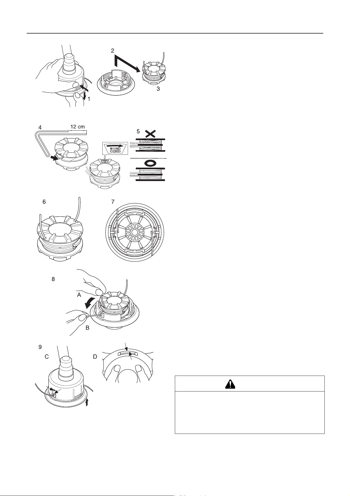
Wartung und Pflege
1. Drücken Sie die Rückhaltestifte (an beiden Seiten) nach
innen, und entfernen Sie den Deckel. Es ist leichter, ein Teil
nach dem anderen zu entfernen.
2. Entfernen Sie die Fadenspule.
3. Wenn der Nylonfaden auf der Spule aufgebraucht ist,
entfernen Sie den Rest des Fadens, und wickeln Sie den
neuen Faden gemäß der Anleitung ab Punkt (4) wieder auf.
Wenn der Nylonfaden auf der Spule geschmolzen ist und
feststeckt, entfernen Sie den Faden vollständig, schneiden
Sie das beschädigte Fadenstück ab, und wickeln Sie den
verbleibenden Faden gemäß der Anleitung ab Punkt (4)
wieder auf.
4. Stecken Sie den Knick des Fadens in den Schlitz der
Unterteilung. Beachten Sie dabei, dass ein Ende des
Fadens ca. 12 cm länger als das andere ist.
5. Wickeln Sie den Nylonfaden fest in Pfeilrichtung auf die
Fadenspule.
6. Wenn Sie beim Aufwickeln des Faden ans Ende kommen,
klemmen Sie die beiden Fadenenden vorläufig so in die
Schlitze der Fadenspule ein, dass noch ungefähr 10 cm
Faden überstehen.
7. Richten Sie die Schlitze mit dem eingeklemmten Faden so
aus, dass sie sich direkt über den Fadendurchführungen
befinden, und passen Sie die Spule in den Deckel ein.
8. Ziehen Sie den Faden aus dem Deckel. Lösen Sie (A) den
Faden aus den entsprechenden Schlitzen der Fadenspule,
und führen Sie ihn (B) durch die beiden
Fadendurchführungen.
9. Fügen Sie Deckel und Gehäuse zusammen. Ordnen Sie (C)
die Fadenösen des Deckels über den Aussparungen in der
Fadenspule an, und drücken Sie (D) die beiden Stifte des
Gehäuses ganz in die Aussparungen der Fadenspule, bis
sie fest in die Fenster einrasten.
GEFAHR
Vergewissern Sie sich, dass die Stifte vollständig in die
Fenster der Fadenspule eingerastet sind. Wenn sie nur
leicht hineingesteckt sind und sich der Fadenkopf zu
drehen beginnt, können sich der Deckel oder innere Teile
lösen und davon geschleudert werden, was sehr
gefährlich ist.
26
Page 93

Wartung und Pflege
Fehlerbehebung
WICHTIG
Verwenden Sie nur Original-Ersatzteile und -Verbrauchsprodukte, die für das Gerät zugelassen sind.
Die Verwendung von Teilen anderer Hersteller oder nicht zugelassener Produkte kann zu Fehlfunktionen führen.
Problem Diagnose Ursache Lösung
Der Motor lässt
sich nicht starten.
Motor lässt sich
schwer starten,
Drehzahl schwankt
Motor springt an,
Drehzahl lässt sich
jedoch nicht
erhöhen.
Der Motor geht aus 1. Falsch justierter Vergaser.
Der Motor lässt
sich nicht
ausschalten
Schneidvorrichtung
dreht sich,
während Motor mit
Leerlaufdrehzahl
läuft
Kraftstoff tritt in das
Überlaufrohr ein
In das Überlaufrohr tritt kein
Kraftstoff ein.
Die Zündkerze ist verschmutzt
oder feucht.
1. Im Kraftstofftank ist kein Kraftstoff
2. Der Aus-Schalter steht auf „Stop"
3. Es wurde zuviel Kraftstoff angesaugt
4. Elektrischer Defekt
5. Vergaser defekt oder innerlich verklebt
6. Interner Defekt des Motors.
1. Kraftstoffalterung
2. Vergaserstörung
1. Kraftstofffilter ist verstopft
2. Kraftstoffsystem ist verstopft
3. Innere Vergaserteile sind verklebt
1. Kraftstoffalterung
2. Falscher Elektrodenabstand
3. Kohlenstoffablagerungen
4. Elektrischer Defekt
1. Verschmutzter Luftfilter
2. Verschmutzter Kraftstofffilter
3. Verstopfte Kraftstoffleitung
4. Falsch justierter Vergaser.
5. Verstopfte Auspuff- oder
Schalldämpferöffnung
2. Elektrischer Defekt
1. Aus-Schalter defekt 1. Not-Halt durchführen
1. Falsch justierter Vergaser.
2. Beschädigte Kupplungsfeder
1. Kraftstoffversorgung
2. Auf „Start" stellen
3. Motor nach Wartung
starten
4. Wenden Sie sich an
Ihren Händler.
5. Wenden Sie sich an
Ihren Händler.
6. Wenden Sie sich an
Ihren Händler.
1. Kraftstoff durch
neuen ersetzen
2. Wenden Sie sich an
Ihren Händler.
1. Reinigen oder
ersetzen
2. Wenden Sie sich an
Ihren Händler.
3. Wenden Sie sich an
Ihren Händler.
1. Ersetzen
2. Ersetzen
3. Ersetzen
4. Wenden Sie sich an
Ihren Händler.
1. Reinigen oder
ersetzen
2. Reinigen oder
ersetzen
3. Wenden Sie sich an
Ihren Händler.
4. Justieren
5. Reinigen
1. Justieren
2. Wenden Sie sich an
Ihren Händler.
und Händler um Rat
fragen
1. Justieren
2. Wenden Sie sich an
Ihren Händler.
Bei Problemen oder Störungen, die nicht in der obigen Tabelle genannt werden, wenden Sie sich an Ihren Händler.
Informationen zur vorschriftsmäßigen Entsorgung des Produkts oder seiner Einzelteile erhalten Sie bei Ihrem Händler.
27
Page 94

Wartung und Pflege
Hersteller:
YAMABIKO CORPORATION
7-2 SUEHIROCHO 1-CHOME, OHME, TOKIO 198-8760, JAPAN
Autorisierter Repräsentant in Europa:
Atlantic Bridge Limited
Atlantic House, PO Box 4800, Earley, Reading RG5 4GB, Vereingtes Königreich
LAGERUNG
Langfristige Lagerung (30 Tage und länger)
WARNUNG
Lagern Sie das Gerät nicht in verschlossenen Räumen, aus denen Kraftsto ffverdunstungen nicht
entweichen können, und nicht in der Nähe von Flammen oder Funken.
Brandgefahr.
Gehen Sie folgendermaßen vor, wenn Sie das Produkt lange Zeit lagern möchten (30 Tage und länger):
1. Entfernen Sie den gesamten Kraftstoff aus dem
Kraftstofftank.
2. Entfernen Sie den Kraftstoff aus der Kraftstoffpumpe, indem
Sie sie mehrmals drücken und wieder loslassen.
3. Starten Sie den Motor, und lassen Sie ihn mit
Leerlaufdrehzahl laufen, bis er von selbst ausgeht.
4. Stellen Sie den Zündschalter (A) auf „Stop".
5. Wischen Sie Schmierfett, Öl, Staub, Schmutz und andere
Ablagerungen außen am Trimmer ab, sobald das Gerät
ausreichend abgekühlt ist.
6. Führen Sie die regelmäßigen Überprüfungen durch, die in
dieser Bedienungsanleitung beschrieben sind.
7. Vergewissern Sie sich, dass Schrauben und Muttern fest
angezogen sind. Ziehen Sie lose Schrauben und Muttern
fest.
8. Entfernen sie die Zündkerze (B) und füllen Sie die
erforderliche Menge (ca. 10 ml) frisches Zweitaktmotoröl
durch die Zündkerzenöffnung in den Zylinder ein.
9. Legen Sie ein sauberes Tuch über die Zündkerzenöffnung.
10. Ziehen Sie zwei- bis dreimal am Startergriff, um das Motoröl
im Zylinder zu verteilen.
11. Beobachten Sie die Lage des Kolben s durch die
Zündkerzenöffnung. Ziehen Sie am Griff des
Reversierstarters, bis der Kolben den oberen Totpunkt
erreicht, und belassen Sie den Griff in dieser Stellung.
12. Bauen Sie die Zündkerze ein (Schließen Sie den
Zündkerzenstecker (C) nicht an.)
13. Bringen Sie die Messerab deckung am Trimmermesser an,
umhüllen Sie den Motorbereich mit einem Kunststoffsack
oder Ähnlichem, und lagern Sie das Gerät an einem
trockenen, staubfreien Ort außerhalb der Reichweite von
Kindern.
28
Page 95

Technische Daten
Technische Daten
RM-520ES
Außenabmessungen:
Länge × Breite × Höhe 2828 × 449 × 564 mm
Gewicht:
Gerät mit leerem Tank, ohne Schneidvorrichtung und Schutzschild
(ISO11806)
Gerät mit vollem Tank, vorgeschriebener Schneidvorrichtung,
Schutzschild und Schultergurt
Fassungsvermögen:Kraftstofftank 1,0 L
Schneidvorrichtung:
Nylonfadenkopf
Schnnittbreite Nylonfadenkopf (Schneisenschneider)
Vorgeschriebener Messerdurchmesser (Option)
Vorgeschriebene Messerdicke (Option)
Anzahl der Schneidzähne (Option)
Durchmesser des Schneidmesserzentrierlochs
Messerdrehzahl bei maximal zulässiger Motordrehzahl
Untersetzungsverhältnis: Untersetzungsverhältnis und Schmierung 1,33 Reduktion und wärmebeständiges
Drehrichtung des Werkzeugaufnahmebolzens von oben
gesehen:
12,0 kg
13,7 kg
Z5
430 mm
255 mm
3,0 mm
3
25,4 mm
10000 U/min
Langzeitschmierfett
Gegen den Uhrzeigersinn
Motor: Typ Luftgekühlter Zweitakt-Einzylindermotor
3
Hubraum
Maximale Motorleistung nach ISO 8893
Motordrehzahl bei maximaler Motorleistung
Empfohlene maximale Motordrehzahl (mit angebrachter
Standardschneidvorrichtung)
Empfohlene Leerlaufdrehzahl
Vergaser
Zündung
Zündkerze
Anlasser
Kupplung
Kraftstoff:
50,2 mL (cm
2,16 kW
9.000 min
10.900 min
2.800 min
Membrantyp
Schwungradmagnet - CDI-System
NGK BPMR8A
Reversierstarter
Automatische Fliehkraftkupplung
Bleifreies Normalbenzin. Verwenden Sie bleifreies
)
-1
-1
-1
Benzin mit mindestens 89 Oktan. Verwenden Sie
keinen Kraftstoff mit Methylalkohol oder mehr als 10%
Öl
Ethylalkohol.
Motoröl für luftgekühlte Zweitaktmotoren. ISO-L-EGD
Standard (ISO/CD 13738), JASO FC,FD und ECHO
Premium 50:1 Öl.
Verhältnis
Kraftstoffverbrauch bei maximaler Motorleistung
Spezifischer Kraftstoffverbrauch bei maximaler Motorleistung
Schwingungspegel: (ISO 22867)a
hv, eq
50:1 (2%)
1,23 L/h
423 g/kW•h
Vorderer Griff 5,3 m/s
Hinterer Griff 4,0 m/s
Unsicherheit 1,2 m/s
2
2
2
Schalldruckpegel: (ISO 22868) LpAeq 97,5 dB(A)
Unsicherheit 1,5 dB(A)
Garantierter Schallleistungspegel:(ISO 22868) L
WA
114 dB(A)
Änderungen der technischen Daten vorbehalten.
29
Page 96

Konformitätserklärung
Der unterzeichnete Hersteller:
YAMABIKO CORPORATION
7-2 SUEHIROCHO 1-CHOME
OHME, TOKIO 198-8760
JAPAN
Diese Konformitätserklärung wird unter der alleinigen Verantwortung des Herstellers
erstellt.
erklärt, dass das nachstehend spezifizierte neue Gerät:
RASENTRIMMER/MOTORSENSE
Marke: ECHO
Typ: RM-520ES
Konformitätserklärung
Folgendem entspricht:
* Anforderungen der Richtlinie 2006/42/EG (Verwendung der harmonisierten Norm ISO 11806-2: 2011)
* Anforderungen der Richtlinie 2004/108/EG (Verwendung der harmonisierten Norm EN ISO 14982: 2009)
* Anforderungen der Richtlinie 2000/14/EG
Konformitätsermittlung nach ANHANG V
Gemessener Schallleistungspegel: 111 dB(A)
Garantierter Schallleistungspegel: 114 dB(A)
Seriennummer 37001001 und höher
Tokio, 1. Oktober 2015
YAMABIKO CORPORATION
Der Dokumentenbevollmächtigte in Europa, welcher
autorisiert ist, die technischen Daten zusammenzustellen.
Unternehmen: Atlantic Bridge Limited
Adresse: Atlantic House, PO Box 4800, Earley, Reading RG5
4GB, Vereinigtes Königreich
Masayuki Kimura Herr Philip Wicks
Hauptabteilungsleiter
Abteilung Qualitätssicherung
30
Page 97

Gewährleistungs- und Garantiebestimmungen für
Gewährleistungs- und Garantiebestimmungen für ECHO- Motorgeräte
31
Page 98

1Notizen und hintere Umschl agseite
7-2 SUEHIROCHO 1-CHOME, OHME, TOKIO 198-8760, JAPAN
TELEFON: 81-428-32-6118. FAX: 81-428-32-6145.
©
2015
X750-026430
X750222-7500
Gedruckt in Japan
0x0xxxx zzzz ES
32
Page 99

1Coperchio
ITALIANO
(Istruzioni originali)
MANUALE PER L’OPERATORE
DECESPUGLIATORE/BORDATORE
RM-520ES
AVVERTENZA
LEGGERE E SEGUIRE ATTENTAMENTE LE ISTRUZIONI PER
LAVORARE IN CONDIZIONI DI MASSIMA SICUREZZA.
LA MANCATA OSSERVANZA DELLE ISTRUZIONI POTREBBE
PROVOCARE LESIONI GRAVI.
Page 100

Contenuto
Per un uso sicuro del prodotto............................................................................................3
Descrizione.........................................................................................................................8
Prima di iniziare............................................ ... .... ... ... ... .... ... ... ... .... ... ... ... ... .... ... ... ...............9
Contenuto della confezione......................................................... ... ... ... .........................9
Montaggio....................................................................................................................10
Preparazione del carburante ................................ .................................................... ... 12
Funzionamento del motore........ ... ... .................................................... ... ... .... ... ... .............13
Avviamento del motore................................................................................................13
Arresto del motore.......................................................................................................14
Operazioni di taglio...........................................................................................................15
Funzionamento base del taglio con testina a filo di nylon ...........................................16
Funzionamento base del taglio con disco metallico ....................................................18
Manutenzione e cura........................................................................................................20
Guida alla manutenzione.............................................................................................20
Manutenzione e cura...................................................................................................20
Rimessaggio................................................................................................................28
Caratteristiche tecniche ............................. ... ... .... ... ... ... .... ... ... ... .... ...................................29
Dichiarazione di conformità ....... ... ... .... .............................................................................30
2
 Loading...