

Page 1

OPERATOR’S MANUAL
BEDIENUNGSANLEITUNG
MANUALE D’ISTRUZIONI
MANUAL DE INSTRUCCIONES
RM-410ES
ENGLISH
DEUTSCH
ITALIANO
GB
DE
IT
ES
ESPAÑOL
WARNUNG
LESEN SIE DIE BEDIENUNGSANLEITUNG SORGFÄLTIG DURCH,
UND BEFOLGEN SIE DIE SICHERHEITSREGELN. ANDERNFALLS
BESTEHT DAS RISIKO SCHWERER VERLETZUNGEN.
WARNING
READ INSTRUCTIONS CAREFULLY AND FOLLOW THE RULES
FOR SAFE OPERATION.
FAILURE TO DO SO COULD RESULT IN SERIOUS INJURY.
AVVERTENZA
LEGGERE E SEGUIRE ATTENTAMENTE LE ISTRUZIONI PER
LAVORARE IN CONDIZIONI DI MASSIMA SICUREZZA.
LA MANCATA OSSERVANZA DELLE ISTRUZIONI POTREBBE
PROVOCARE LESIONI GRAVI.
ADVERTENCIA
LEA ATENTAMENTE LAS INSTRUCCIONES Y SIGA LAS
INDICACIONES PARA UN FUNCIONAMIENTO SEGURO. DE NO
HACERLO, PODRÍA SUFRIR LESIONES GRAVES.
Page 2

Page 3

1Cover
ENGLISH
OPERATOR'S MANUAL
RM-410ES
WARNING
READ THE INSTRUCTIONS CAREFULLY AND FOLLOW THE
RULES FOR SAFE OPERATION.
FAILURE TO DO SO COULD RESULT IN SERIOUS INJURY.
Page 4

2
Important information
2Important information
Please ensure that you read the operator's manual before using your product.
Intended use of this product
ECHO Grass Trimmers/Brushcutters are lightweight, high-performance, petrol engined units designed for weed con-
trol, grass trimming and brush cutting in areas difficult to control by any other means.
Do not use this unit for any purpose other than aforementioned.
Users of the product
You should not use this product until you have read the operator's manual carefully and fully absorbed its content.
This product should not be used by anyone who has failed to read the operator's manual properly, is suffering from a
cold, tiredness or otherwise in poor physical condition, or children.
Keep in mind that the operator or user is responsible for accidents or hazards occurring to other people or their prop-
erty.
About your operator's manual
This manual contains n ecessary inf ormation ab out the ass embly, ope ration, and maintenance of your produc t. Please
read it carefully and absorb its contents.
Always keep your manual in a place where it is readily accessible.
If you have lost your manual or it is damaged and no longer readable, please purchase a new one from your ECHO
DEALER.
The units used in thi s manual are SI u nits (Inte rnational Sys tem of Unit s). Figures in parentheses are reference va lues,
and there may be a slight conversion error in some cases.
Loaning or assigning your product
When loaning the produc t described in t his manual to anoth er party, ensure th at the person borrowi ng and working with
the product receives the operat or's ma nual alo ng with the prod uct. If you assign yo ur prod uct to anot her party, pl ease
enclose the operator's manual with the product when handing it over.
Enquiries
Please contact your ECHO DEALER for requests regarding information about your product, the purchase of consum-
ables, repairs, and other such enquiries.
Notices
The content of this manual may be changed without notice for the purpose of upgrades to the product. Some of the
illustrations used may differ from the product itself in order to make the explanations clearer.
This product requires the assembly of some parts.
Please consult your ECHO DEALER if anything is unclear or of concern.
Page 5

3
Contents
For safe use of your product...............................................................................................4
Warning notices.............................................................................................................4
Other indicators .............................................................................................................4
Symbols.........................................................................................................................4
Location in which a safety decal is attached..................................................................6
Handling fuel . ....... ...... ....... ...... ....... ...... ....... ...... ....... ...... ...... ..........................................7
Handling the engine.................................... ...... ....... ...... ...... ..........................................8
Handling the product ........................................................... ....... ...... ....... ...... ....... ...... ... 9
Packing list........................................................................................................................14
Description........................................................................................................................15
Before you start ................................................................................................................16
Assembly.....................................................................................................................16
Preparing the fuel ........................................................................................................20
Engine operation...............................................................................................................21
Starting the engine ......................................................................................................21
Stopping the engine.................................... ...... ....... ...... ............................................. .23
Trimming operation...........................................................................................................24
Basic trimming operation with nylon line cutting head.................................................25
Basic trimming operation with metal blade..................................................................26
Precautions to observe when working.........................................................................28
Maintenance and care ........................................................ ...... ....... .................................29
Servicing guidelines.....................................................................................................29
Maintenance and care .................................................................................................29
Storage .............................................................................................................................38
Long-term storage (30 days or more)..........................................................................38
Specifications....................................................................................................................39
Declaration "CE" of conformity .........................................................................................40
Page 6

4
For safe use of your product
For safe use of your product
Be careful to read this section before using your product.
The precautions described in this section contain important safety information. Please observe them carefully.
You must also read the precautions that appear in the body of the manual itself.
Text following a [diamond mark] mark describes the potential consequences of failing to observe the precaution.
Warning notices
Situations where there is a risk of phy sic al inju ry to the op erator and other people are indicated in this manual and on th e product
itself by the following warning notices. Always read and observe them carefully in order to ensure safe operation.
Other indicators
As well as warning notices, this manual uses the following explanatory symbols:
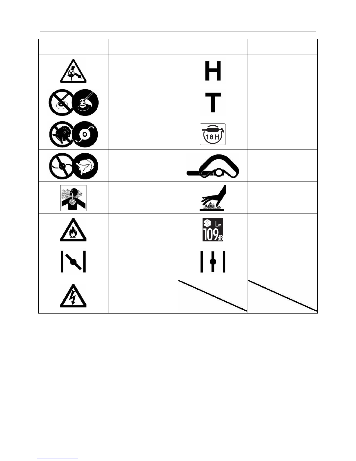
Symbols
In this manual and on th e produc t it self, a series of explan ator y symbo ls is used. Pl ease mak e sure that yo u fully unders tand w hat
each symbol means.
DANGER WARNING CAUTION
This symbol accompanied by the
word "DANGER" calls attentions to
an act or a condition which will lead to
serious personal injury or death of operators and bystanders.
This symbol accompanied by the
word "WARNING" calls attentions to
an act or a condition which can lead to
serious personal inj ury or death o f operators and bystanders.
"CAUTION" indicates a potentially
hazardous situation which, if not
avoided, may result in minor or moderate injury.
Circle and sl ash symbol means whatever is
shown is prohibited.
NOTE IMPORTANT
This enclosed messa ge provid es tips
for use, care and maintenance of the
product.
Framed text featuring the word "IM-
PORTANT" contains important information about the use, checking,
maintenance and storag e of the product described in this manual.
Symbol form/shape Symbol description/applica-
tion
Symbol form/shape Symbol description/applica-
tion
Carefully read the operator's
manual
The maximum speed of the
cutting attachment shaft in
r/min
Wear eyes, ears and head
protection
Keep bystandars away 15 m
Wear foot protection and
gloves
Petrol and oil mixture
Emergency stop Purge bulb (Primer)
Warning!
Thrown objects!
Carburettor adjustment
- Low speed mixture
Page 7
5
For safe use of your product
Waring, side thrust
Carburettor adjustment
- High speed mixture
Usage without shield not permitted
Carburettor adjustment
- Idle speed
Usage of metal blades not
permitted
Lubricate in every 18 hours
Usage of nylon line cutting
head not permitted
Loop handle
Do not use the produc t in places with poor ventilation
Beware of high-temperature
areas
Beware of fire
Guaranteed sound power level
Choke Control "Cold Start"
Position (Choke Closed)
Choke Control "Run" Position
(Choke Open)
Beware of electric shocks
Symbol form/shape Symbol description/applica-
tion
Symbol form/shape Symbol description/applica-
tion
Page 8
6
For safe use of your product
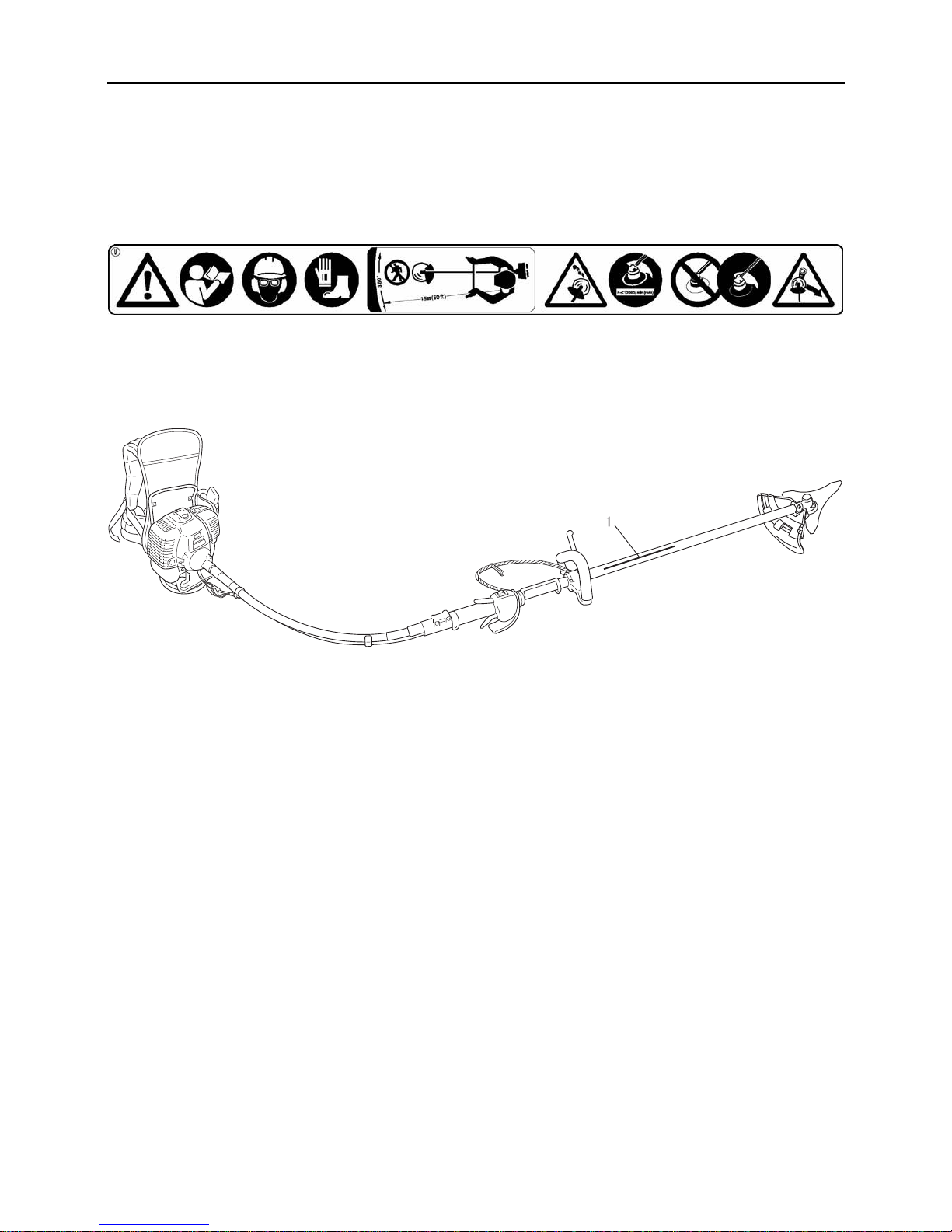
Location in which a safety decal is attached
The safety decal shown below has been attached to the products described in this manual. Ensure that you understand what
the decal means before using your product.
If the decal b ecomes unreada ble due to w ear and tear or damage, or peels off an d is lost, pl ease purchase a replaceme nt decal
from your ECHO DEALER and attach it in the location shown in the illustrati ons be low. Ensure that the decal is readable at all
times.
1. Safety decal (Part number 890617-43130)
Page 9

7
For safe use of your product
Handling fuel
DANGER
Always keep well away from fire when refuelling
Fuel is highly inflammable and leads to a risk of fire if mishandled. Use extre me c ar e whe n m i xing , sto ring or handling
or serious personal injury may result. Be careful to observe the following instructions.
Do not smoke or hold a flame near when refuelling.
Do not fuel up while the engine is hot or in operation.
If you do so, the fuel could ignite and cause fire, leading to burns.
About the container and refuelling place
Use an approved fuel container.
Fuel tanks/cans may be under pressure.
Always loosen fuel caps slowly allowing pressure to
equalize.
DO NOT fill fuel tanks indoors.
ALWAYS fill fuel tanks outdoors over bare ground.
Fuel spills can cause fire
Observe the following precautions when refuelling:
Do not add so much fuel tha t it reaches the mouth of the
fuel tank. Keep the fuel with in the prescribed leve l (up to
the shoulder level of the fuel tank).
Mop up any fuel that overflows or spills out due to over-
filling.
Tighten the fuel tank cap securely after refuelling.
Fuel spills can cause fire and burns when ignited.
1. Fuel tank
2. Shoulder level
Do not start the engin e in the area where you r efueled
You must not start the engine in the place where you
carried out the refuelling. Move at least 3m from the
place where you refueled before starting the engine.
Fuel leaks that occur while refuel-
ling can cause fire if ignited.
Fuel leaks cause fire
After refuelling, always check
that there are no leaks or discharges of fuel from the fuel
pipe, fuel system grommets, or
around the fuel tank cap.
If you do find fuel leaks or discharges, stop using the
product immediately and contact your ECHO DEALER
to have it repaired.
Any fuel leaks could cause fire.
Page 10
8
For safe use of your product
Handling the engine
WARNING
Starting the engine
Be particularly careful to observe the following precautions when starting the engine:
Check that none of the nuts and bolts are loose
Check that there are no fuel leaks
Place the product in a flat, well ventilated place
Leave plenty of space around the product and do not al-
low people or animals near it
Start the engine with the throttle trigger in the idle spee d
position
Hold the product firmly to the ground when starting the
engine
Failure to observe th e precau tions c ould cau se an ac ciden t
or injury, or even lead to a fatality.
Once the engine h as start ed, check for abnormal v ibrations and sounds
Check that there are no abnormal vibrati ons o r soun ds
once the engine starts. Do not use the product if there
are abnormal vibrations or sounds. Co ntact your ECHO
DEALER to have it repaired.
Accidents involving parts that fall or shatter off can cause
wounds or serious injury.
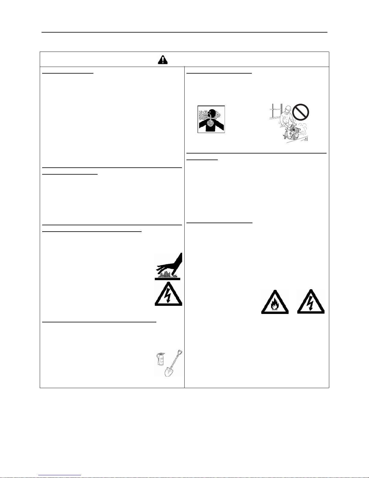
Do not touch high temperature or high voltage components while the product is running
Do not touch the following high temperature or high voltage components while the product is running or for some
time after it stops.
Silencer, spark plug, angle transmission,
and other high temperature components
You could burn yourself if you touch a high
temperature component.
Spark plug, spark plug wire, and other
high voltage components
You could receiv e an electric shock if you
touch a high voltage com po nen t w hil e the
product is running.
Put safety first in the case of fire or smoke
If fire comes from the engine or smoke appears from
any area other than the exhaust vent, first distance
yourself from the product to ensure you r physi cal safety.
Use a shovel to throw sand or other such
material on the fire to prevent it from
spreading, or put it out with a fire extinguisher.
A panicked reactio n could result in the fire and
other damage becoming mo re exte ns ive .
Exhaust fumes are toxic
The exhaust fumes from the engin e contain toxic gases.
Do not operate the product indoors or in other ill ventilated places.
The exhaust fumes could cause poisoning.
Turn off the engine when checking or maintaining
the product
Observe the following precautions when checking and
maintaining your product after use:
Turn the engine off and do not attempt to check or main-
tain the product until the engine has cooled
You could burn yourself.
Remove the spark plug cap before performing checks
and maintenance
An accident cou ld occur if the product starts unexpectedly.
Checking the spark plug
Observe the following precautions when checking the
spark plug.
If the ele ctrodesor terminals are worn, or if there are
cracks in the ceramics, replace them with new parts.
The spark test (for checking whether the spark plug is
sparking) must be carried out by your ECHO DEALER.
The spark test must not be carried out in proximity of
the spark plug hole.
The spark test must not be performed in places where
there are fuel spills or inflammable gases
You must not touch the
metal parts of the spark
plug
The spark plug could ig-
nite a fire or give you an
electric shock.
Page 11

9
For safe use of your product
Handling the product
General precautions
Precautions for use
WARNING
Operator's manual
Be careful to read the operator's manual
properly before using your product in order to ensure correct operation.
Failure to do so could lead to a n accide nt or
serious injury.
Do not use the product for anything
other than its intended purpose
You must not use the product for any purpose other
than those described in the operator's manual.
To do so could lead to an accident or serious injury.
Do not modify the product
You must not modify the product.
To do so could lead to an accident or serious injury. Any
malfunction resulting from a modification to the product will
not be covered by the manufacturer's warranty.
Do not use the pro duct unless it has been checked
and maintained
You must not use the product unless it has been
checked and maintained. Always ensure that the product is checked and maintained on a regular basis.
Failure to do so could lead to an accident or serious injury.
Loaning or assigning your product
When loaning your product to another party, ensure
that the person borrowing the product receives the operator's manual along with it.
If you assign your product to another party, please en-
close the operator's manual with the product when
handing it over.
Failure to do so could lead to an accident or serious injury.
Being prepared in case of an injury
In the unlikely event of an accident or injury, please ensure
that you are prepared.
First aid kit
Towels and wipes (to stop any bleeding)
Whistle or mobile phone (for calling outside help)
If you are unabl e t o perform first aid or call for outside help,
the injury could worsen.
DANGER
Do not use the product when the trimmer blade is
turning at idle speed
You must not use the product while the trimmer blade is
turning if the Grass Trimmer i s running with the throttle
trigger in the idle speed position.
To do so could lead to an accident or serious injury.
Do not remove the shield
Do not operate the product without the shield in place.
Any objects that ricochet off the trimmer blade could cause
an accident or serious injury.
The area within a 15 m radius is a danger zone
The area within a 15 m radius of the product is a danger
zone. Be careful to observe the following precautions
while working with the product.
Do not allow children and other people or pets to enter
the danger zone.
If another person enters the danger zone, turn off the
engine to stop the blade from rotating
When approaching the operator, signal to him by, for
example, throwing twigs from o utsid e the da nger zon e,
and then check that engine has been switched off and
the blade has stopped turning
If more than one person is working with the product,
identify the way in which you will signal to each other
and work at least 15 m apart
Any objects that rico chet off the t rimmer b lade, and any c on-
tact with the trimmer blade, co uld cause blind ness or a fatal
accident.
Page 12

10
For safe use of your product
WARNING
Users of the product
The product should not be used by:
people who are tired
people who have taken alcohol
people who are on medication
people who are pregnant
people who are in poor physical
condition
people who have not read the op-
erator's manual
children
Failure to observe these instruc-
tions could lead to an accident.
Environment of use and operation
Do not use the product in places where the re is no sure
foothold, such as on steep slopes or after rainfall, as
such places are slippery and dangerous.
Do not operate the product at night or in dark places
with poor visibility.
When using the product on a gentle sl ope, work in a lev-
el, contour-like motion.
A serious injury could result if you fall or slip, or fail to oper-
ate the product correctly.
For your own health and your safe and comfortable
work, operate the machine within the air temperature
range of -5
o
C to 40 oC.
Failure to observe the se instructi ons could res ult in damage
to your health.
Turn off the engine when moving around
When moving around in the situations described below,
turn off the engine and ensure that the trimmer blade has
stopped rotating, then fit the trimmer blade cover and position the silencer away from yourself.
Moving to the place where you are working
Moving to another area while you are working
Leaving the place where you have been working
Failure to obs erve these precautions could cause burns or
serious injury.
When transporting the product by car, empty the fuel
tank, fit the trimmer blade cover, and secure the produ ct
firmly in place to prevent it from moving around.
Travelling by car w ith fuel in th e trimmer tank co uld lead to a
fire.
Vibration and cold
It is believed that a condition called Raynaud's Phenomenon which affects the fingers of certai n individuals may be
brought about by exposure to vibration and cold. Exposure to vibration and cold may cause tingli ng and burning,
followed by loss of colour and numbness in the fingers.
The following precautions are strongly recommended because the minimum exposure which might trigger the ailment is unknown.
Keep your body warm, especially the head and neck,
feet and ankles, and hands and wrists.
Maintain good blood circulation by performing vigorous
arm exercises during frequent work brea ks, and also by
not smoking.
Limit the number of hours of operation.
Try to fill each day with jobs where operating the trimmer or other hand-held power equipment is not required.
If you experience discomfort redness and swelli ng of
the fingers, followed by whitening and loss of feeling,
consult your physician before exposi ng yourself further
to cold and vibration.
Failure to observe th ese instructi ons could result in damage
to your health.
Repetitive stress injuries
It is believed that over-using the muscles and tendons of
the fingers, hands, arms and shoulders may cause soreness, swelling, numbness, weakness and extreme pain to
the areas just mentioned. Certai n repetitive hand activities
may put you at a high risk for developing a repetitive
stress injury (RSI).
To reduce the risk of RSI, do the following:
Avoid using your wrist in a bent, extended or twisted
position.
Take periodic breaks to minimize repetition and rest
your hands. Reduce the speed and force in which you
do the repetitive movement.
Do exercises to strengthen hand and arm muscles.
See a doctor if you feel tingling, numbness or pain in
your fingers, hands, wrists or arms. The sooner RSI is
diagnosed, the more likely permanent nerve and muscle
damage can be prevented.
Failure to observe th ese instructi ons could result in damage
to your health.
Proper training
Do not permit operation without proper training and protective equipment.
Be thoroughly familiar with the controls and proper use of unit.
Know how to stop the unit and shut off the engine.
Know how to unhook a harnessed unit quickly.
Never allow anyone to use the unit without proper instruction.
Page 13
11
For safe use of your product
WARNING
Remove foreign objects and obstructions before working with the
product
Before starting work, check the area where you will be working and re-
move any small stones an d em pty cans lik ely to r icoche t off the cu tting
attachment, as well as any pieces of string or wire that might become
twisted around the cutting attachment.
An accident or serious injury can occur if foreign objects ricochet off the cut-
ting attachment or wire and other materials twisted round the product spring
off it.
Do not hold the cutting attachment up when working with the product
Do not hold the cutting attachment up while you work. You m ust not work with the cutting attac hments raised above
knee level.
Raising the cutting attachmen t above knee level brings the plane of rotatio n closer t o the face, and an y objects that fly off the
cutting attachments could cause an accident or serious injury.
Turn off the engine immediately if anything goes wrong
In the following situations, turn off the engine immediately and ensure that the cutting attachments have stopped before checking each area of the product. Replace any damaged parts.
If the cutting attachment hits a rock , tree, post, or other such obstruction while you work.
If the product suddenly starts to vibrate abnormally.
Continuing to use parts when they are damaged could lead to an accident or serious injury.
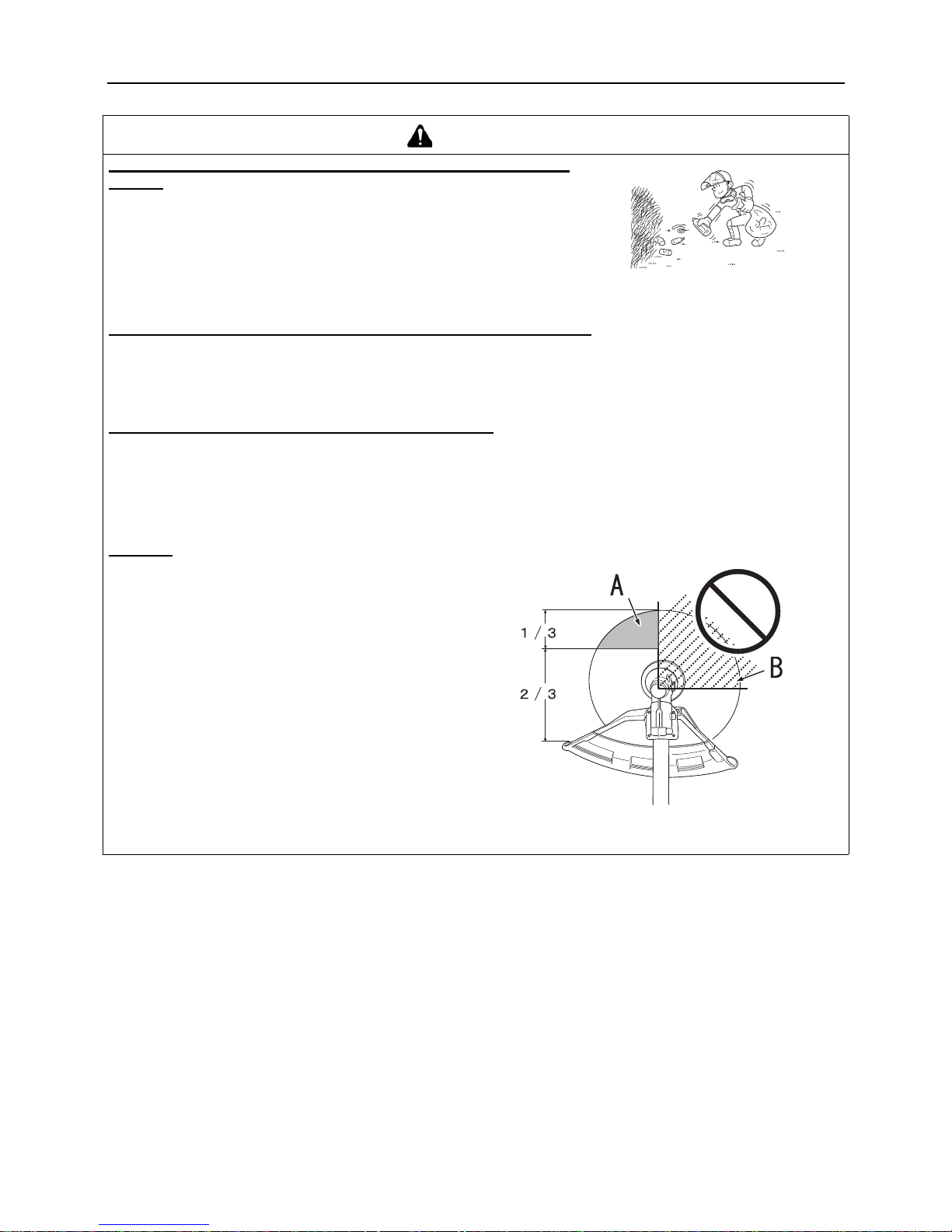
Kickback
The phenomenon that occurs if the trimmer blade
comes into contact with a tree, post, rock or other ha rd
object while rotating at high spe ed and rea cts by recoiling powerfully and instantaneously is known as kickback.
Causing kickback can result in a los s of control over the
product and is highly dangerous.
In particular, if the front-right quadrant of the trimmer
blade (B) strikes a shrub or other such object, the trimmer blade will cause th e p r oduc t to rec oil sha r ply ba ckwards to the right.
To prevent kickback, do not trim from left to right. Be
careful to ensure that the trimmer blade does no t strike
any hard objects.
When tri mming, ensure that the object you are cutting
meets the portion of the blade 1/3 in from the front edge
on the left-hand side (A).
Failure to do so could cause an injury or fatal accident.
Page 14

12
For safe use of your product
Precautions concerning the cutting attachment
1.With metal blade
2.With nylon line cutting head
DANGER
Always stop the engine whe n a cut ting attac hment ja m occu rs. Do not attem pt to remov e an ob ject ca using a jam if th e
engine is running. Severe injury can occur if a jam is removed and the cutting attachment suddenly starts.
WARNING
Use correct blades
Serious injury may result from the improper use of
blades.
Read and comply with all sa fety instructions listed in
this manual.
The 3 cutter blade is designed especially to cut weeds
and grass. To avoid i njury due to kickbac k or blade fracture, do not use the 3 cu tter blade to cu t brush o r trees.
Use only cutting attachments recommended by KIOR-
ITZ CORPORATION.
Damaged or shattered blades can cause accidents and se-
rious injury.
Inspect blade before use
Pieces from a cracked metal blade can fly off during operation. Inspect metal blades for cracks before each use.
Discard cracked blades no matter how small the crack.
Cracked blades can be the resul t of the mis use or im proper sharpening.
Damaged or shattered blades can cause accidents and se-
rious injury.
Reaction forces
Be sure you understand the reaction forces of push and
pull, and kickback described in this manual, and how
these forces may affect your balance in the operation of a
unit.
Failure to do so could cause an injury or fatal accident.
WARNING
Use correct cutting attachment
Serious injury may result from the improper use of cut-
ting attachment.
Read and comply with all sa fety instructions listed in
this manual.
Use only cutting attachments recommended by KIOR-
ITZ CORPORATION.
Use only nylon line cutting hea d. Do not use a ny type of
metal blade.
Failure to do so could lead to an accident or serious injury.
Excessive nylon line beyond cut off knife could fly off
when the nylon line cutti ng head starts rota ting after adjustment of nylon line length.
Failure to do so could lead to an accident or injury.
Do not trim near cars or pedestrians
Use extreme caution when operating over bare spots and
gravel, because the line can throw small rock particles at
high speeds. The shield on the unit cannot stop objects
which bounce or ricochet off hard surfaces.
Failure to do so could lead to an accident or serious injury.
Avoid wire
Do not trim in any area where there are broken strands of
fencing wire. Remove the broken pieces of wire, or give the
area wide berth. Wear proper saf ety protec tion. Do no t cut
where you cannot see what the cutting device is cutting.
Failure to do so could lead to an accident or serious injury.
CAUTION
Use only flexible, non-metallic line recommended by KIORITZ CORPORATION.
Page 15
13
For safe use of your product
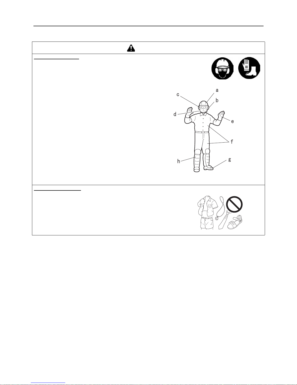
Protective gear
WARNING
Wear protective gear
Always wear the following protective gear when working
with the trimmer.
a Head protection (helmet): Pro tec ts the hea d
b Ear muffs or ear plugs: Protect the hearing
c Safety goggles: Protect the eyes
d Face shie ld: Protects the face
e Safety gloves: Protect the hands from cold and vibration
f Work clothes that fit (long sleeves, long trousers): Pro-
tect the body
g Heavy du ty, non-slip protecti ve boots (with toec aps) or
non-slip work shoes (with toecaps): Protect the feet
h Shin guards: Protect the legs
Failure to observe the se precautions c ould result in dama ge
to your sight or hearing, or lead to a serious injury.
When necessary, please use the protective gear below.
Dust mask: Protects the breathing apparatus
Bee net: To deal with attacks by bees
Wear proper clothing.
Do not wear ties, jewellery, or loose, dangling clothing which could be
caught in the unit. Do not wear open toed footwear, or go bare-foot or
barelegged. In certain situations, total face and head protection may be required. For heavy brush cutting with metal blade, logger's trousers or leg
chaps with protective inserts are added considerations.
Failure to observe these precautions could result in damage to your sight or
hearing, or lead to a serious injury.
Page 16

14
Packing list
Packing list
The following parts are packed separately in the pack ing box.
When you have unpacked the box, please check the parts that it contains.
Contact your ECHO DEALER if anything is missing or broken.
Engine
Operation Shaft
1. Engine
2. 3 cutter blade
3. Safety goggles (ANSI Z 87.1 compliant)
4. Caution tag
5. Operator's manual
6. Shield (for metal blade)
7. Shield (for nylon line cutting head)
8. Convex of fitting plate
9. Bolt M5×25
10. Cut off knife
11. Screw 5×12
12. Locking tool
13. Socket wrench
14. Hexagonal wrench
15. Flexible shaft assembly
16. Shaft tube
17. Blade cover
18. Front handle
19. Strap
Page 17

15
Description
Description
1. Cutting attachment 3 c utte r b lad e f or c ut ting grass, garden debris and weeds.
2. Shield Device to protect the operator from accidental
contact with the cutting head and thrown objects.
3. Angle transmission Having two gears to change to angle of rotating axis.
4. Shaft tube Part o f the unit that provides a casing for pow er transmission shaft.
5. Front handle Handle loc at ed t ow ard s t he c utting device.
6. Strap Rubber strap to hang power transmission shaft.
7. Ignition switch "Slide switch" mounted on top of the
throttle trigger housing, move switch upward to RUN,
downward to STOP positi on.
8. Throttle trigger Activated by the operator's finger fo r con-
trolling the engine speed.
9. Throttle trigger lockout Locks throttle trigger in the idling
position until you have a proper grip with your right hand
around the handle.
10. Rear handle Handle locate d towards the knapsack power unit.
11. Flexible shaft assembley Flexible tube for the power
transmission shaft.
12. Silencer cover Cover the silen cer not to make operato r
touch to ho t surface of silencer.
13. Spark plug
14. Air cleaner cover Covers air filter.
15. Fuel tank Contains fuel and fuel filter.
16. Fuel tank cap For closing the fuel tank.
17. Starter handle Pull handle to start the engine.
18. Blade cover When transpor ting the unit, us e the app ropriate metal blade cover.
Page 18
16
Before you start
Before you start
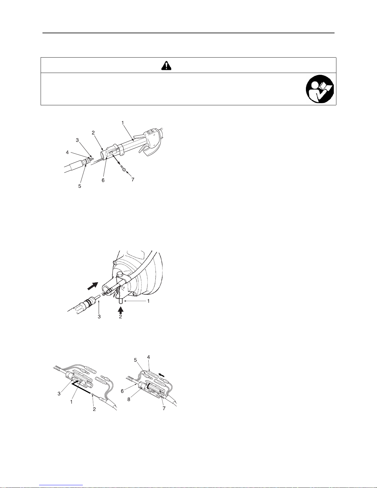
Assembly
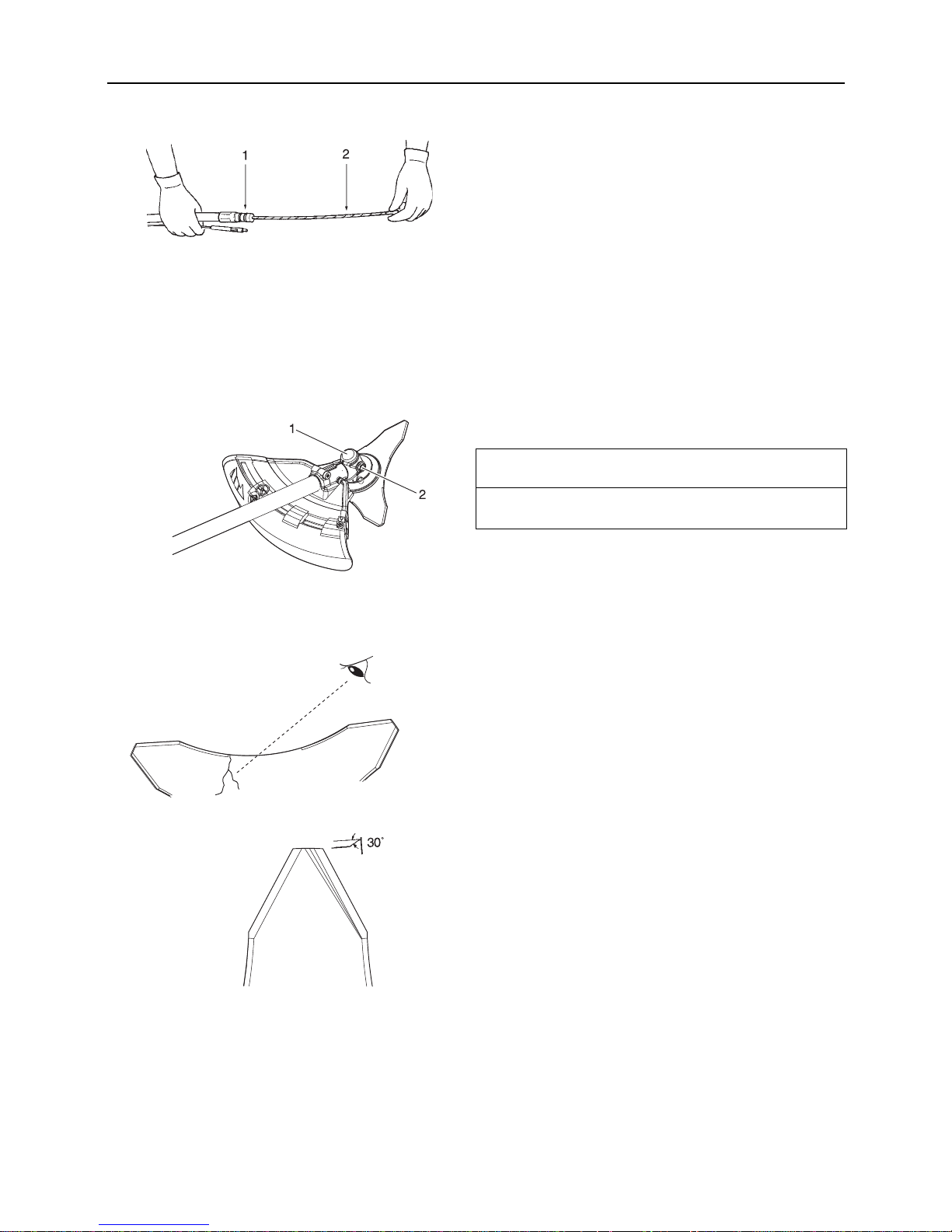
Flexible shaft assembly
First stage of assembling is coupling of the power transmission
shaft (F) and (R).
Loosen bolt with hexagonal wrench.
Insert the power tran smission shaft (R) with the spacer into the
socket gradually and fully. - The socket is assembled on the
power transmission shaft (F) and located inside of the rear
handle. - The spacer that is located at the end of the power
transmission shaft (R) prevents the shaft (R) from loosening
off.
Insert connector into holder and tighten bolt securely us ing
hexagonal wrench.
Second stage is coupling of the po wer transmissio n shaft (R) and
the engine.
As pushing in the lock pin fully, insert the other end of power
transmission (R) to the driving sh aft of the engin e. - For easier
coupling, pull out the power transmission (R) about 4 mm
more in advance.
After set the lock pin free, confirm that the flexible shaft as-
sembly can not be drawn out and i s coup led pro perly wi th the
engine.
Throttle cable retainer assembly
This assembly is designed to provide a simple connection and
adjustment for the throttle cable.
Hook inner cable te rminal into join t, set the cable in holder and
shut cover (A).
Connect lead (A) and lead (B).
WARNING
Read the operator's manual carefully to ensure that you assemble the product correctly.
Using a product that has been incorrectly assembled could lead to an accident or serious injury.
1. Power transm ission
shaft (F)
2. Holder
3. Power transm ission
shaft (R)
4. Spacer
5. Connector
6. Socket
7. Bolt
1. Lock pin
2. Push
3. Power transmission
shaft (R)
1. Joint
2. Inner ca ble
3. Holder
4. Lead (A)
5. Lead (B)
6. Throttle cable
7. Cover (A)
8. Cover (B)
Page 19
17
Before you start
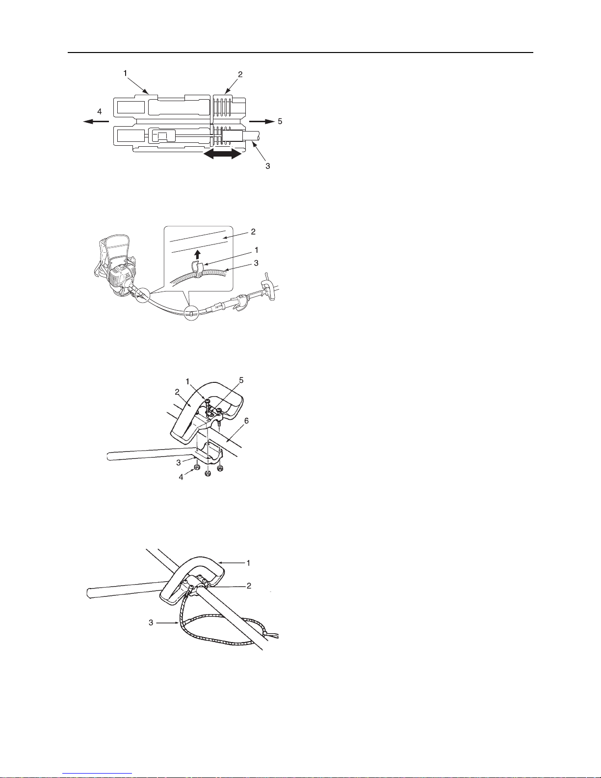
The length of in ner cable can be a djusted for pro per pulling by
opening cover (B) and resetting flange of throttle cable into a
suitable groove on the left or right.
The 2 pieces of clip attached to flexible shaft assembly must
be set to appropriate positions on the throttle cable (at epual
distance on the whole length of the flexible shaft assembly).
Loop handle
Assemble the front handle and bracket on the shaft tube
loosely.
Adjust the location of the front handle to a convenient position.
Tighten the screws (M5×35 ) and nuts securely . - One of the 4
screws must be tighten together with the hanger a s illustrated .
Shoulder harness
Suit the length of knapsack band to comfort.
As the strap is elastic and adjustable, it is preferable to con-
nect the strap to the hangers located on the front handle and
the left or right knapsack band to maintain a fatigueless and
comfortable operation.
1. Cover (A)
2. Cover (B)
3. Throttle cable
4. Engine side
5. Shaft tube side
1. Clip
2. Flexible shaft assembly
3. Throttle cable
1. Screw M5×35
2. Front handle
3. Bracket
4. Nut
5. Hanger
6. Shaft tube
1. Front handle
2. Hanger
3. Strap
Page 20
18
Before you start
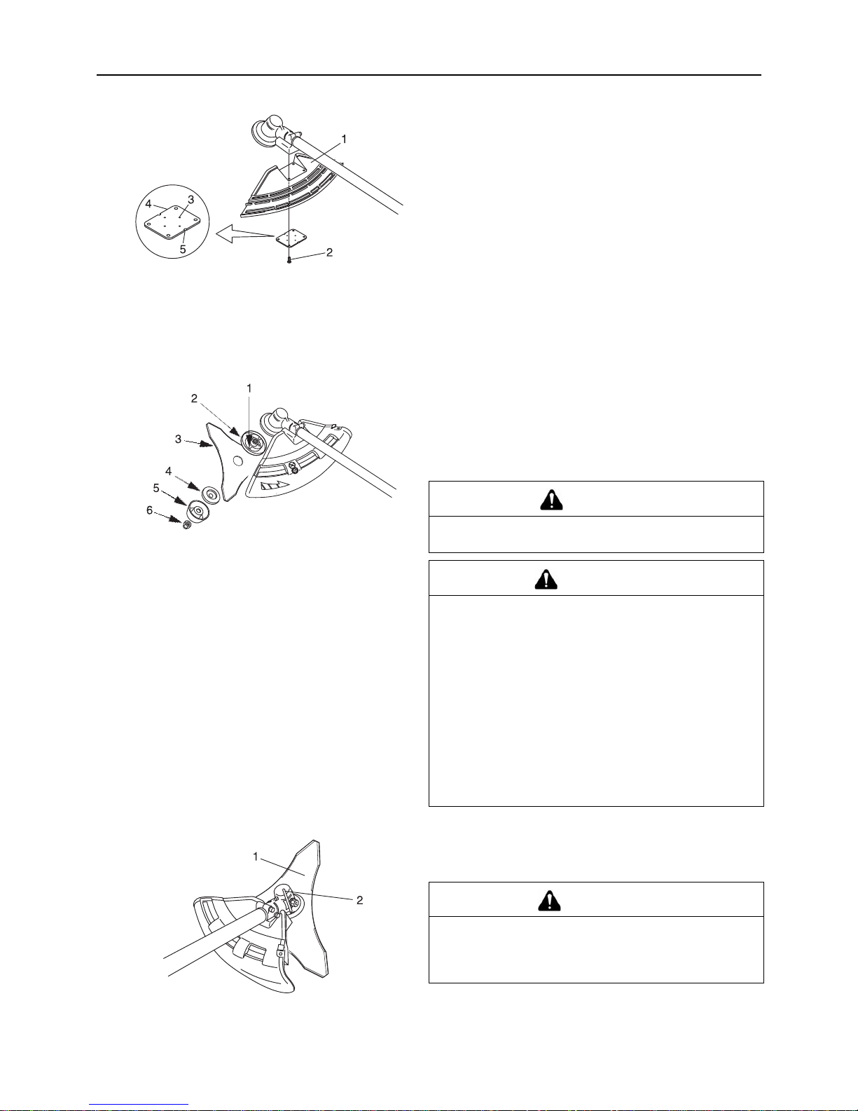
Installation of bracket
Fit bracket to mounting portion of angle transmission and fix the
bracket by holding fittin g pl ate p res sed from ben eat h and tighten
4 bolts (M5×25) lightly.
Get notches and convexes of fitting plate to face corresponding
convexes and concaves of bracket, and fix bracket tightening 4
bolts (M5×25) securely.
There are two types of shields: namely one used exclusively for
nylon line cutting h ead and a nother one used ex clusive ly for metal blade. When metal blade is used, use the shield for metal
blade.
Installing blade
Inspect blades before installation. Check for sharpness.
Dull blades increase the risk of blade kickback reactions.
Small cracks can develop into fractures resulting in a piece of
blade flying off during operation.
Discard cracked blades no matter how small the crack.
Blade retainer, blade, lower blade retainer, cup and nut finger
tight.
Insert locking tool into a hole located on the right side of angle
transmission while forcing retainer spring to the left side. Insert
locking tool further into b lade retainer fixin g slot to fix output s haft.
1. Bracket
2. Bolt M5×25
3. Convex of fitting plate
4. Fitting plate
5. Notch of fitting plate
1. Blade retainer fixi ng slot
2. Blade retainer
3. Blade
4. Lower blade retainer
5. Cup
6. Nut
DANGER
If worn nut and cup for blade are used, there is a danger of
blade getting loose. Replace them with new one.
WARNING
Do not attempt to fit the tri mmer blade with one hand or
without using the socket spanner. Fit the trimmer blade
accurately using the supplie d socket spanner and ti ghten firmly in position.
The trimmer must not be used i f the blade vibrates or is
loose.
Wear heavy duty gloves when working with the trimmer
blade. When replacing the trimmer blade during a trimming task, ensure that the engine is switched off and
that the blades have stopped.
When turning the product over to replace the trimmer
blade, ensure that the fuel ta nk cap is securel y in place.
Failure to do so could lead to an injury or serious accident,
or cause a fire.
1. Blade 2. Locking tool
CAUTION
Fasten output shaft using locki ng tool s ecurely i n order to
avoid the possibility of output shaft rotating when mounting cutting blade which will prevent the cutting blade fastening nut from being tightened sufficiently.
Page 21

19
Before you start
Tighten the nut (turn anticlockwise) using a socket wrench.
Never fasten while app ly ing y ou r we ight. Otherwise the thread of
nut could be broken.
Replace nut and cup with ne w ones no matter ho w small the wear
is.
1. Socket wrench 2. Blade
Page 22

20
Before you start
Preparing the fuel
Fuel
Fuel is a mixture of regular grade petrol and an air-cooled 2-
stroke engine oil of reputable brand name.
Minimum 89 Octane unl eaded petrol is recommended . Do not
use fuel containing methyl alcohol or more than 10 % of ethyl
alcohol.
Recommended mixture ratio; 50 : 1 (2 %) for ISO-L-EGD
Standard (ISO/CD 13738), JASO FC,FD grade and ECHO
Premium 50 : 1 o il.
- Do not mix directly in engine fuel tank.
- Avoid spilling petrol or oil. Spilled fuel should always be
wiped up.
- Handle petrol with care, it is highly inflammable.
- Always store fuel in approved container.
Fuel supply
Always refuel in a well ventil ated location. Do not pour fuel in-
doors.
Place the produc t an d the refuelling tank on the ground when
performing the refuelling operation. Do not refuel the product
on the loading platform of a truck, or in other such places.
Always ensure that the fuel level remains below the shoulder
level of the fuel tank when refuelling.
There is a difference in pressure between the fuel ta nk and the
outside air. When refu elling, loosen the fuel ta nk cap slightly to
eliminate the difference in pressure.
Always wipe up any fuel spills.
Move at least 3m away from where you refueled before you
start the engine.
Keep the refuelling tank in a shaded area away from fire.
DANGER
Fuel is highly inflammable and ther e is a risk of fire if it is handled incorrectly. Carefully read
and observe the precautions in the sectio n of this manual title d "For safe use of you r product".
Once the refuelling is complete, securely tighten the fuel tank cap and do not forget to
check that there are no leak s or discharges of fuel from th e fuel pipe, fuel system gromm ets,
or around the fuel tank cap. If you do find fuel leaks or discharges, stop using the product
immediately and contact your ECHO DEALER to have it repaired.
If the fuel ignites, it could cause burns and fire.
CAUTION
There is difference in pressure between the fuel tank and the outside air. When refuelling, loosen the fuel tank cap
slightly to eliminate the difference in pressure.
Otherwise, fuel may get spewed.
NOTE
Stored fuel ages. Do not mix more fuel than you expect use in thirty (30) days. Do not mix directly in fuel tank.
1. Fuel tank 2. Shoulder level
Page 23

21
Engine operation
Engine operation
Starting the engine
Starting a cold engine
(Connect the spark plug cap if the product has been i n storage fo r
a long period of time)
The starting procedu re depen ds on w hethe r the eng ine is cold o r
warm. A cold engine is started as follows.
1. Remove the trimmer blade cover and check the trimmer
blade. If anything is wrong, replace it with a new one.
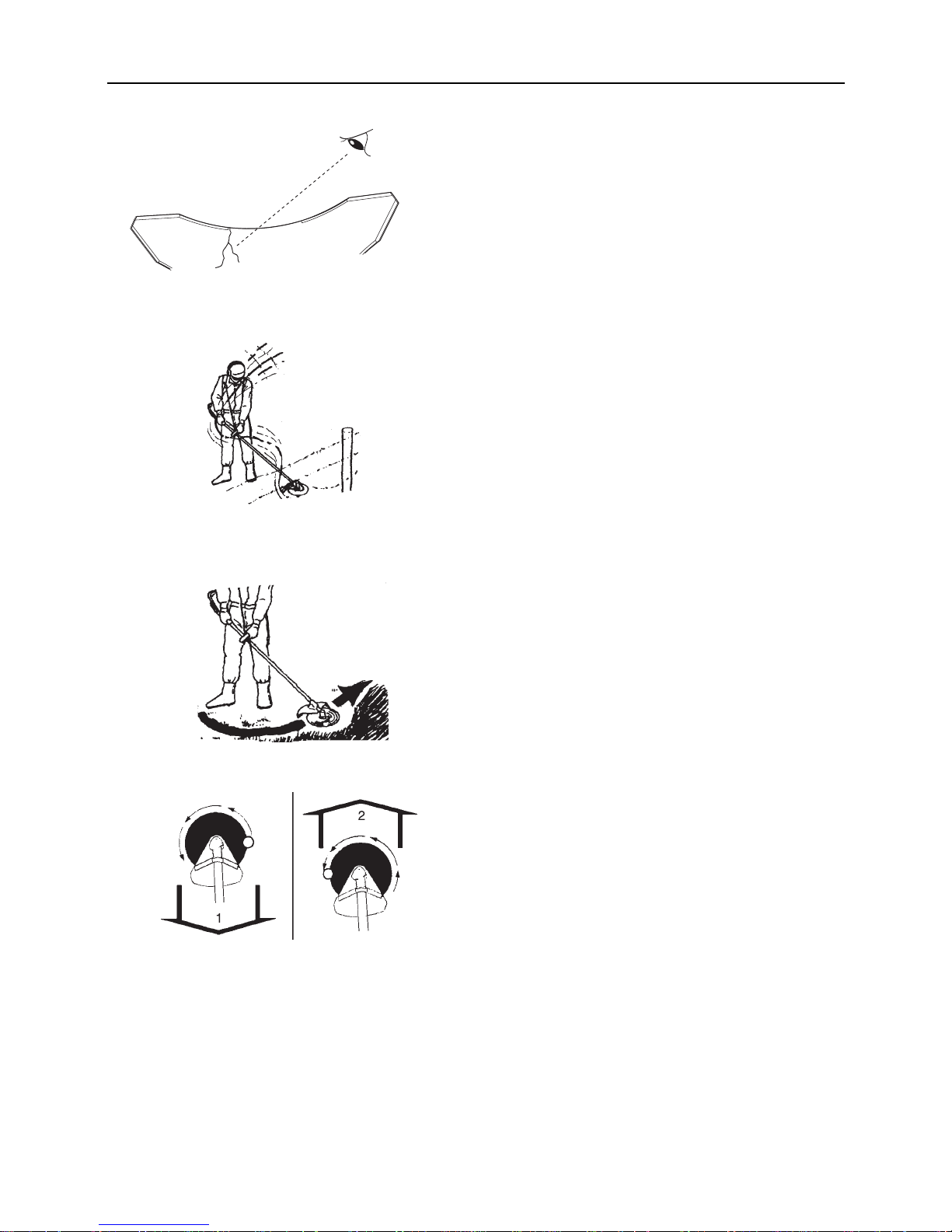
2. Placing the product on l evel ground, check t o ensure that the
blade does not come into contact with the surface of the
ground or any other impedim ent using a beam or other such
implement.
3. Check that there are no fuel leaks.
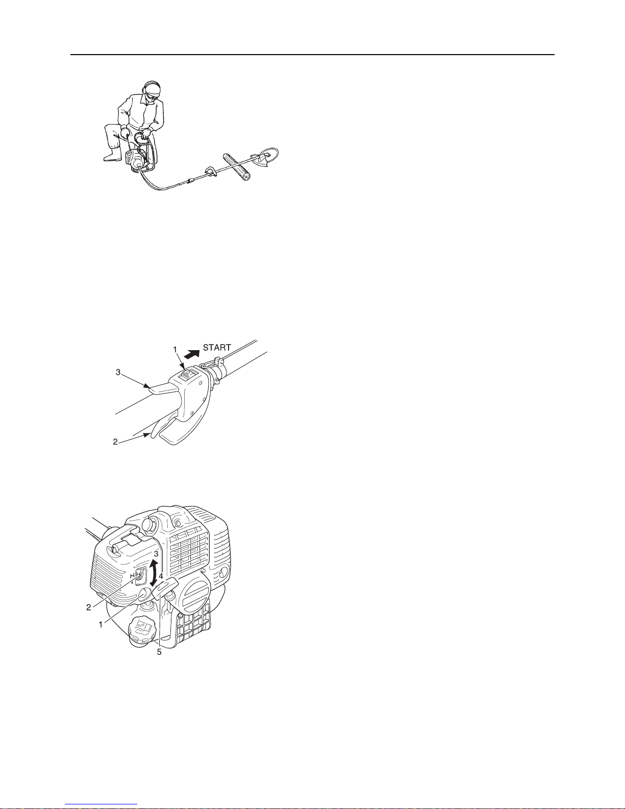
4. Move the ignition switch to the Start position.
5. Make sure that the throttle trigger is at the idle speed position.
6. Move the choke lever to the "Cold Start" position.
7. Alternately press and release the purge bu lb until the fuel is
sucked up into it.
WARNING
When starting the engine, observe the precautio ns describe d from Page 4 i n the s ectio n "For safe us e of your prod-
uct" to ensure that you operate the product correctly.
If thecutting attachment rotates even though the thrott le trigger is in the idle speed position w hen the engine is start-
ed, adjust the carburettor before using the product.
Failure to observe the precautions could cause an accident or injury, or even lead to a fatality.
NOTE
Pull out the starter grip gently at first, and then more rapidly. Do not pull the starter rope out to more than 2/3 of its length.
Do not let go of the starter grip as it returns.
1. Ignition switch
2. Throttle trigger
3. Throttle trigger lockout
1. Purge bulb
2. Choke lever
3. Cold Start (CLOSE)
4. Run (OPEN)
5. Starter handle
Page 24
22
Engine operation
8. Checking that the area aro und yo u is safe , hold the posit ion
closest to the engine firmly as shown in the illustration, pulling several times on the starter grip .
9. If you hear an explosion-like sound and the engi ne stops im mediately, move the choke lever to the "Run" position and
continue pulling on the starter grip to start the engine.
10. If the engine starts immediately when you carry out the instructions in step 8, above, return the choke lever gently to
the "Run" position.
11. Leave the engine to warm up at idle speed for a while.
Engine warm-up
1. Once the engine starts, allow it to warm up for 2 to 3 minutes
at idling (i.e. low speed).
2. Warming the engine helps to lubricate its internal workings
more smoothly. Allow the engine to warm up fully , especially
when it is cold.
3. Never run the engine without the cutting attachment fitted.
Starting a warm engine
1. Move the ignition switch to the Start position.
2. Make sure that the throttle trigger is at the idle speed position.
3. Check that the chok e lever is in the "Run" position.
4. If fuel tank is not empty, pull on the starter grip to start the
engine.
5. If no fuel is visible in the purge bu lb, alterna tely press a nd release the purge bulb until the fuel is sucked up into it.
6. Checking that the area around you is safe, hold the position
closest to the engin e firmly, and pull on the starter grip to star t
the engine.
1. Ignition switch
2. Throttle trigger
3. Throttle trigger lockout
1. Purge bulb
2. Choke lever
3. Cold Start (CLOSE)
4. Run (OPEN)
5. Starter handle
Page 25

23
Engine operation
Stopping the engine
1. Move the throttle trigger to the idle speed position and set
the engine to idling (i.e. low speed).
2. Move the ignition switch to the Stop position.
3. In the event of an emergency, stop the engine immediately
using the ignition switch.
4. If the engine fails to stop, move the choke lever to t he "Cold
Start" position. The engine will stall and come to a halt (an
emergency stop).
∗ If the engine fails to stop wh en the ignition swi tch is used, have
the ignition switch checked and re paired by your E CHO DEALER before you use the product again.
Always disconnect t he spark plug wire from the spark plug to en sure the engine cannot be started before you work on the unit or
leave it unattended.
1. Ignition switch 2. Throttle trigger
1. Spark plug wire 2. Spark plug
Page 26
24
Trimming operation
Trimming operation
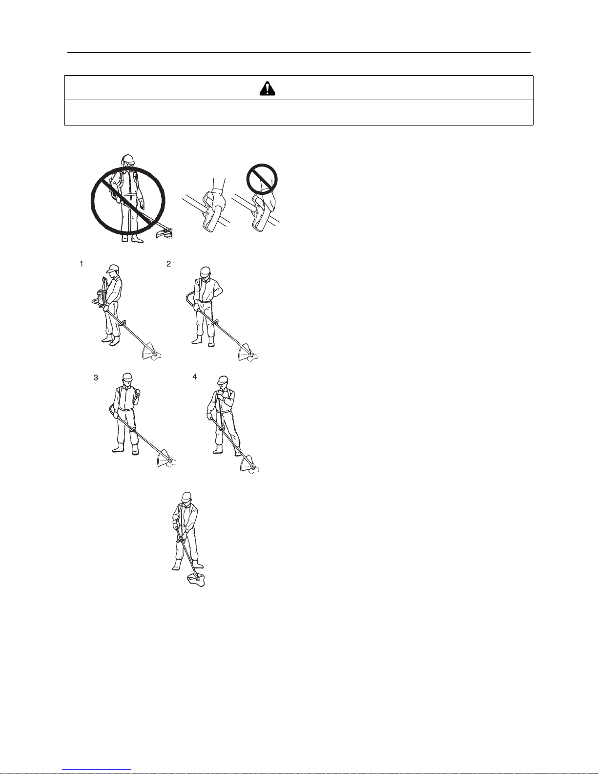
Never attempt to operate the product with one hand.
Ensure that you hook your thumbs a round the grips , wrapping
them in your thumb and remaining fingers.
1. Hold the rear handle of shaft tube in le ft han d and hang the
right knapsack band on the right shoulder.
2. Hold the rear handle of shaft tube in ri ght hand and h ang the
left knapsack band on the left shoulder.
3. For even load on both sides of shoulder, joggle the unit on
the shoulder a couple of times.
4. It is preferable to conn ect the strap to the hangers lo cated on
the loop handle th e left or right knapsack band and adjust the
length of the strap to maintain a comfortable operation.
Increase engine speed as necessary, heavy weeds will require
more power than cutting grass. - Small trees or heavy brush can
be cut using the circ ular saw. - T he 3 cutte r blade sh ould be u sed
only for cutting grass, brush or for heavy weed control.
Hold the front handle (loop handle) and rear handle both hands.
When cutting weeds or g rass, sw ing th e bla de ri ght an d lef t in
an arc as you mo ve forward.
The blade rotates anticlockwise, so it is necessary to cut the
object from the right to the left.
The manner of walking is as follows: - Place the right foot in
front of the left foot without fail. - Step the right foot forward
firstly and secure y our footin g. - And th en follow the left f oot to
the behind of the right foot.
Avoid striking any obstruction such as rocks, stones or tree
stumps which can damage the blade. - In the event that the
blade strikes an obstructi on or is otherwise prevented from rotating in normal op erat ion , the clutch will slip to prevent possible engine damage. - In this case, stop the engine, free the
blade and then start the operation again.
Do not cut into the ground.
Do not run the unit unl oaded at full thrott le to av oid dama ge to
the engine.
Should the unit be operated for an extended period of time in
high temperatures, the angle transmission may become very
hot. If it is too hot to touch, allow the unit to cool down, check
the lubricant as the i nstruc tion an d cont inue to operate if in o rder.
DANGER
Always stop the engine whe n a cut ting attac hment ja m occu rs. Do not attem pt to remov e an ob ject ca using a jam if th e
engine is running. Severe injury can occur if a jam is removed and the cutting attachment suddenly starts.
Page 27
25
Trimming operation
Basic trimming operation with nylon line cutting head
The basic cutting actions
The basic cu tting actons pictured are:
Trimming, scything, scalping and lawn edging.
These actions are as follows:
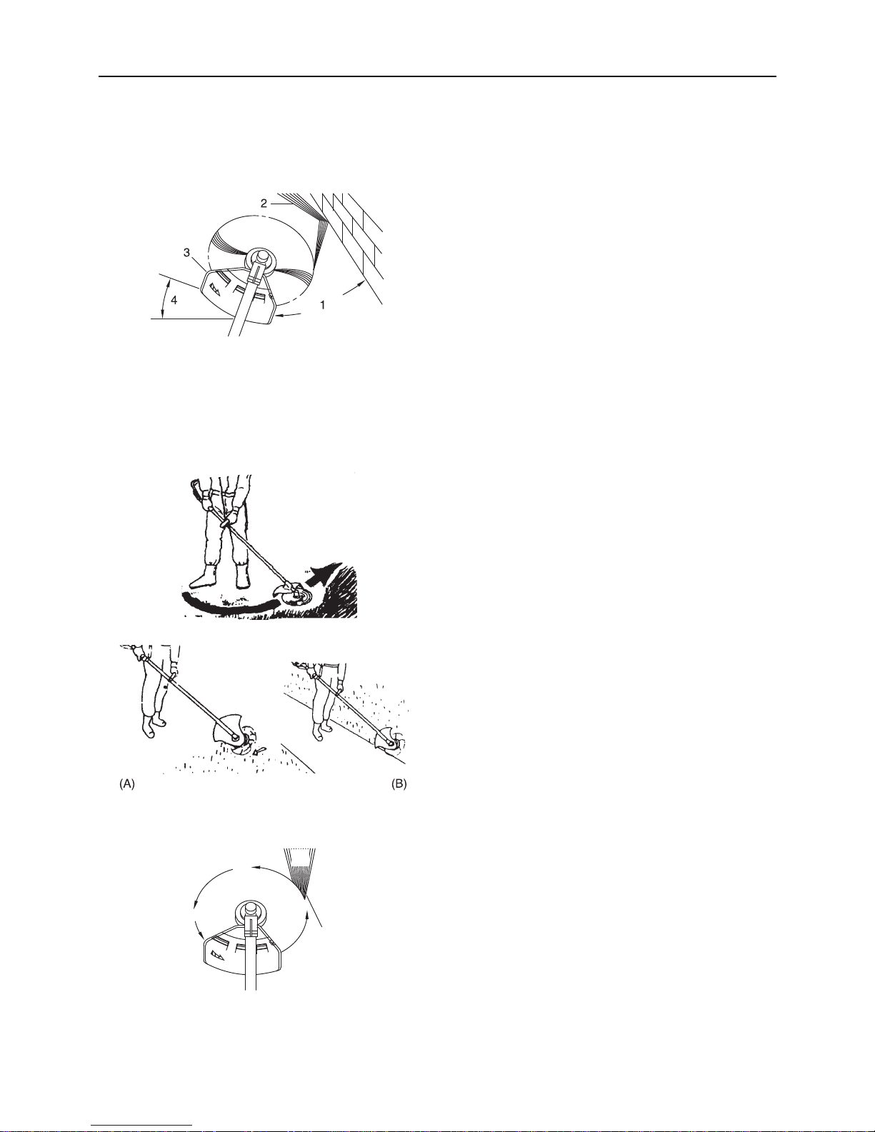
Trimming
This is feeding the trimmer carefu ll y int o the mate rial you wish to
cut. Tilt the head slig htly to direc t the debris awa y from you. If cutting up to a barrier such as a fence, wall or tree, approach from
an angle where any debris ric ocheti ng off the barrier wil l fly away
from you.
Move the nylon lin e cutti ng hea d slowly un til the grass i s cut r ight
up to the barrier, but do not jam (overfeed) the line into the barrier. If trimming up wire mesh or chain link fencing, be careful to
feed only up to the wire. If you go too far, the line will snap off
around the wire.
Trimming can be done to cut through weed stems one at a time.
Place the nylon line cutting head near the bottom of the weed
never hig h u p, w hic h c o ul d ca us e the w e ed t o ch a tte r and c at c h
the line. Rather than cu t the w eed rig ht throu gh, jus t use t he very
end of the line to wear through the stem slowly.
Scything
This is the cutting or mowing of large grassy areas by sweeping
or swinging the trimmer in a level arc. Use a smooth, easy motion. Do not try to hack or cho p down th e gra ss. Tilt t he nyl on line
cutting head to direct the debris away from you on the scything
stroke. Then return w ithout cutting grass f or another s troke. If you
are well protected and do not care whet her some debris is thrown
in your direction, you may scythe in both directions.
Scalping and edging
Both of these are done with the nylon line cutting head tilted at a
steep angle. Scalping is removing top growth, leaving the earth
bare. Edging is trimming the grass ba ck where it h as spread over
a pavement or driveway. During both edging and scalping, hold
the unit at a steep angle in a position where the debris, and any
dislodged di r t an d s t on e, w ill n ot co me b ac k t owa rd s yo u ev en if
it ricochets off the hard surface.
Although the pictures show ho w to edg e and sc alp, every operator must find for himself the angles which suit his body size and
cutting situation.
For nearly all cutting, it is good to tilt the nylon line cutting head
so that contact is made on the part of line circle where the line is
moving away from you and the shield (See appropriate picture).
This results in the debris being thrown away from you.
Tilting the head to the wrong side will shoot the debris toward
you. If the nylon line cutting head is held fl at to the ground s o that
cutting occurs on the whole line circle, debris will be thrown at
you, drag will slow the engine, and you will use up a lot of line.
1. Angle to w all
2. Debris
3. Knife side raised
4. Angle to ground
A: Scalping B: Edging
Nylon line cutting head rotates anticlockwise.
The knife will be on the le ft side of the shield.
1. Debris
2. Cut on this side
1
2
Page 28
26
Trimming operation
Always wear proper eye protection against thrown objects.
Objects can bounce up at you from the ground under the shield,
or ricochet off any nearby hard surface.
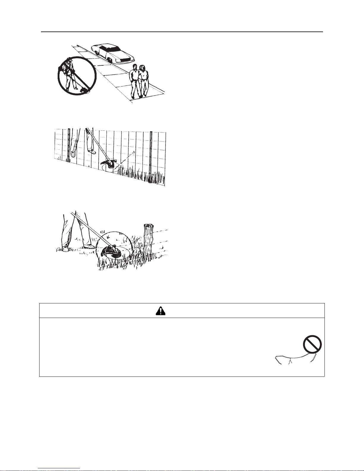
Do not trim at high speed near roadways when there is traffic, or
in places where there are pedestrians. If you must trim where
people are in the zone of risk use a much lower or reduced
speed, by using a partial trigger setting. Do not use full throttle.
Do not push the line into tough weeds, trees, or wire fences.
Pushing the line into chicken wire, chain link fencing or thick
brush can result in sn apped-off line ends being h urled back at the
operator. The proper way is to cut right up to a barrier, such as
any of those mentio ne d, but never run the line into or throu gh the
obstruction. Do not cut closely to obstruction or barrier.
Avoid nylon line contact with broken wire fencing. Pieces of wire
broken off by the trimmer can be hurled at high speeds.
Basic trimming operation with metal blade
Do not trim near cars or pedestrians.
Line pushed into wire fencing will snap off.
Avoid wire
WARNING
Please observe the following instructions when trimming.
Ensure that the trimmer blade doe s not come into c ontact with hard obs tructions such a s stone, m etal, or concrete.
If the blade hits an obstruction, turn off the engine imme diately and ensure that the blade has
stopped before checking the blade and shield for damage.
Never use cracked blades, as they could fly off while you are working.
Check to ensure that the trimmer blade has been tightened securely in place.
Replace the shield if it is damaged or cracked.
Replace the trimmer blade nut when it becomes worn.
Failure to do so could lead to an accident or serious injury.
Page 29
27
Trimming operation
Use correct blade
Always use the blade suited for the job.
Do not allow the t rimme r blade to come into co ntact w ith har d
obstructions such as stone, concrete or metal.
Do not cut into the ground with the blade.
If the blade hit s an obstruction , turn the engine o ff immediately
and ensure that the trim mer blade has stopped rotating before
checking the blade and shield for damage.
Do not operate with a dull, b ent, fractured or discoloured b lade
and worn or damaged nut.
Never use a crac ked trimmer blade as it could shatte r off while
you are worki ng.
Do not run engine at full throttle without a load.
Remove all foreign objects from work area.
Do not operate brushcutter without shield.
Scything weeds
This is cutting by s wing ing the cutting att achment in a level arc. I t
can quickly clear areas of field grass an d weeds. Scything should
not be used to cut large, tough weeds or woody growths.
If a sapling or shrub binds the cu ttin g attachment, do not use the
cutting attachment as a lever to free the bind, because this will
cause cutting attachment failure.
Instead, shut off the engine an d push th e sapli ng or shrub to free
the blades.
Do not use a cracked or damaged blade.
Reaction forces
Push.
The operator may feel the unit push toward him when he tries to
cut the object on right. If he cannot hold the blade in the cut, a
kickback may occur when the blade is pushed out to where the
teeth at the outside furthest point from the operator are cutting.
The blade will "kickback" sideways.
Pull.
The opposite of push. When obj ec t on le ft, th e ope rato r may feel
the unit pull away. Alt hough this p ull type of cu tting may cau se
sawdust to be thrown bac k at the oper ator, it is rec ommended fo r
sawing off heavy brush because the cutting is smoother and
more stable than when the unit pushes.
Inspect blades before use
Wires can catch and flap around
Anticlockwise rotation 1. Push 2. Pull
Page 30

28
Trimming operation
Kickback.
If you hit a hard object with the front-right of the trimmer blade,
such as when trimming in both directions, the blade will kick
sharply back to the right. This is a phenomenon known as "kick
back", and can cause a seri ous ac cid en t due to the ope rato r los ing control over the product. Take particular care to ensure that
you do not strike any hard object with th e front-right of the trimmer
blade.
Precautions to observe when working
The area within a radius of 15m of the product is a danger
zone. Make sure that there are no children, onlookers, or pets
in this zone. If anyone comes within 15m, turn off the engine
immediately to stop the blade from rotating.
If someone is helping you with the work or you are working to-
gether, identify the way in which you will signal to each other
and work at least 15m apart. You are advi sed to carry a whis tle
in case you need to communicate.
Turn off the engine imm edia tely if th e product s uddenl y starts
to vibrate abnormally. Sudden vibration may be caused by a
problem with a component such as the flywheel, clutch, or
trimmer blade, or by a loose screw or oth er such factor. Do no t
use the product until you hav e identified the cause of the problem and the repair has been completed.
The trimmer blade could fly off unless tightened securely. En-
sure that it is fitted securely in place.
Replace the shield if it is damaged or cracked.
If you work wit h t he ang le tra nsmiss ion in cont act w ith t he su r-
face of the ground, the trimmer blade nut and cup can easily
become worn. Replace them with new parts if this happens.
When you turn off the engi ne, check to ensure that the trim mer
blade has stopped ro tating before you lower the product to the
ground. Even if the engin e ha s been turned o ff, the bl ade can
still cause an injury while free-wheeling.
The silencer will remain hot for some tim e after the engine has
been turned off. Carry the product with the si lencer away from
you to avoid touching it with your body.
When carrying the product, always turn the engine off and fit
the trimmer blade cover over the trimmer blade.
Kickback
Page 31

29
Maintenance and care
Maintenance and care
Servicing guidelines
Maintenance and care
Cleaning air filter
Close choke. Loosen screw and remove air cleaner cover.
Remove air filter (air filter is located inside air cleaner cover).
Brush dirt from fi lter or clean wit h compressed air. Do not wash
the air filter.
Reinstall air filter with cover, after installing air filter to cover.
Tighten screw.
Area Maintenance Page Before use Monthly
Air filter Clean/Replace 29 •
Fuel filter Inspect/Clean/Replace 30 •
Spark plug Inspect/Clean/Adjust/Replace 31 •
Carburettor Adjust/Replace and adjust 30 •
Cooling system Inspect/Clean 30 •
Silencer Inspect/Tighten/Clean 31 •
Flexible shaft Grease 32 •*
Angle transmission Grease 32 •**
Starter Inspect - •
Cut off knife Inspect/Clean - •
Fuel system Inspect 31 •
Screws, bolts and nuts Inspect, Tighten/Replace - •
IMPORTANT
Time intervals are maximum. Actual use and your experience will determine the frequency of required maintenance.
* Or 18 hours, whichever occurs first.
** Or 50 hours, whichever occurs first.
If you have any questions or problems, please contact your ECHO DEALER.
1. Air filter 2. Air cleaner cover
Page 32

30
Maintenance and care
Replacing fuel filter
Use a piece of metal wire or the like to pick up fuel filter
through fuel tank opening.
Pull old filter from fuel line.
Install new fuel filter.
Carburettor adjustment
Every unit is test run at the factory and the carburettor is fine
tuned for maximum performance.
Before adjusting carburettor, clean or replace air filter, start engine and run several minu tes to bring it to operating t emperature.
To adjust the carburettor proceed as follow:
Turn "idle" speed a djustment scre w (T) clockwis e until cutting
atttachment begins to turn, then turn screw(T) out anticlockwise until cutting attachment stops turning. Turn screw (T)
out, anticlockwise, and additional 1/4 turn.
Cooling system maintenance
1. Fuel filter 2. Fuel line
NOTE
If filter is excessive dirty or no longer fits properly, replace it.
WARNING
When carburettor adjustment is comple ted, cutt ing attac hment sh ould not mov e at idle, oth erwise serious p ersonal i njury may result.
CAUTION
When starting, idle speed adjuster (T) should be adjusted not to rotate the cutting attachment.
When there is some trouble with the carburettor, contact your dealer.
T: Idle speed adjustment screw
IMPORTANT
To maintain proper engine operating temperature, cooling air must pass freely through the cylinder fin area. This flow
of air carries combustion heat away from the engine.
Overheating and engine seizure can occur when:
Air intakes are blocked, preventing cooling air from reaching the cylinder,
or
Dust and grass build up on the out si de of the cylinder. This build -up insulates the engine and prevents the heat from
leaving.
Removal of cooling passage blockag es or cleaning of cylind er fins is considered "Norm al Maintenanc e". Any resultant
failure attributed to lack of maintenance is not warranted.
Page 33

31
Maintenance and care
Remove dust and dirt from between fins.
Before each use, remove a ccumulated debris fro m bottom en -
gine intake grille located between the fuel tank and starter.
Cleaning silencer
Remove the silencer cover.
Remove silencer and heat shield.
Place piston at top dea d c entre. Clean deposits from silencer
and cylinder exhaust port.
Inspect heat shield, replace if damaged.
Install heat shield and silencer.
Install silencer cover.
Check fuel system
Check before every use.
After refuelling, make sure fuel does not leak or exude from
around fuel pipe, fuel grommet or fuel tank cap.
In case of fuel leakage or exudation there is a danger of fire.
Stop using the machine im me dia tel y and request your dealer
to inspect or replace.
Check spark plug
Check plug gap. Correct gap is 0.6 mm to 0.7 mm.
Inspect electrode for wear.
Inspect insulator for oil or other deposits.
Replace plug if needed and tighten to 15 N·m - 17 N·m (150
kgf·cm to 170 kgf·cm).
1. Cylinde r fins 2. Air intake
1. Heat shield
2. Silencer
3. Silencer cover
NOTE
Be careful not to scratch the cylinder or piston when cleaning
the cylinder exhaust port.
1. Fuel tank cap
2. Fuel grommet
3. Fuel pipe
a: 0.6 - 0.7 mm
Page 34
32
Maintenance and care
Lubricating flexible shaft
All the surface of the power transmission shaft (R) should al-
ways be properly greased.
At the time of delivery from the plant, this is greased, so ev enly
grease all the surface of the power transmission shaft (R) approximately 10 mL in every 18 hou rs.
The major points necessary for disassembling and reassem-
bling are as follo w s: - As pu sh ing in the lock pin of the engine
fully, draw out the flexible shaft assembly from the engine. Unfasten the couplin g of the flexible sha ft assembly at the grip
end, draw out the flexib le shaft assem bly from the rear handle
assembly. - Then the power transmission shaft (R) with the
spacer can easily draw out from the flexible shaft assembly. Use the same grease as the angle transmission's. - When reassemble, it is preferable to fit the power transmission shaft
(R) reversely, but the spacer is fitted on the rear handle assembly side of the powertransmission shaft (R) at all times.
Angle transmission
Remove plug from angle transmission.
Add grease, if necessary, using low pressure pump.
Reinstall plug.
Checking the blade
Use only blade desig nated for this model by the manufacture r.
When a crack i s noticed o n the blade, do not use it but repla ce
with a new one.
Ensure that the bla de is correctly fitted in ac cordance with the
instructions.
When the cutting blad e becomes dull due to wear re verse it for
further use.
When chip or bend occ urs on the blade, vibratio n will increase .
Replace with new one.
When filing the bla de file 3 cutting edges evenly using a flat file
as shown in the illustration.
Otherwise, the balance will be lost and vib ration will increase.
1. Flexible shaft 2. Power transmission
shaft
1. Angle transmission 2. Plug (Bolt)
NOTE
Use good quality lithium multi grease.
Do not overfill housing.
Page 35
33
Maintenance and care
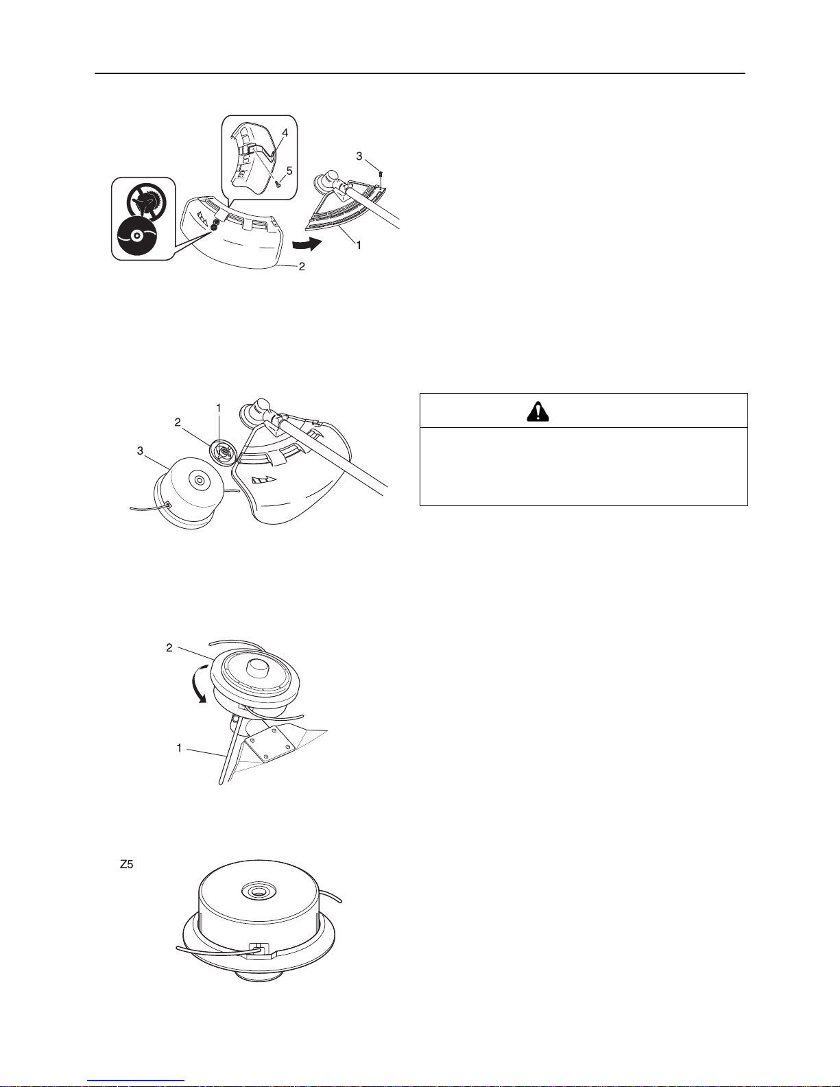
Installing nylon line cutter (option)
Method to change shield
Remove bolt (M5×18) on the ri ght sid e of the sh ield an d slid e the
shield to the left and remove it. Put shield of another type into
groove and slide it to the right until it stops and be sure to fasten
with the removed bolt (M5×18).
Installing nylon line cutting head
Insert locking tool into a hole located on the right side of angle
transmission while forcing retainer spring to the left side. Insert
locking tool further into b lade retainer fixin g slot to fix output s haft.
Thread nylon line cu tting head onto sha ft (anticlo ckwise) u ntil it is
tight.
Remove locking tool.
Nylon line cutting head
Type: Z5
Thread: Left-hand thread M10×1.25 pitch
1. Bracket
2. Shield (for nylon line
cutting head)
3. Bolt M5×18
4. Cut off knife
5. Screw 5×1 2
1. Blade retainer fixi ng slot
2. Blade retainer
3. Nylon line cutting head
CAUTION
Use only flexible, non-metallic line recommended by
KIORITZ CORPORATION.
Fasten output shaft using locking too l securely i n order
to avoid the possibility of output shaft rotating when
mounting nylon line cutting head.
1. Locking tool 2. Nylon line cutting head
Page 36

34
Maintenance and care
Adjusting nylon line
Make sure there is no bystander within 15 m radius and pay
enough attention to objects in the su rroundings before starting
operation.
Do not rotate the nylon line c utting head at more than 1000 0 r/
min.
Do not hit the n ylon line cutting hea d agains t hard forei gn mat-
ters such as rocks, concrete, tree stub and bottle etc.
When releasing nylon line from spool hit tap knob of spool
against the ground surface lightly at rotati on spee d lower th an
4500 r/min.
Cut off knife on th e s hield adjusts cutting swath automatically
by cutting n y lon lines evenly when attachment start s rotating.
When operating with less than maximum cutting swath, cut
two nylon lines in equal lengths.
Replacing nylon line
1. Press "retaining pawls" (at two places) inward and remove
cover.
It is easier to remove one after another.
2. Remove spool.
3. When nylon line on the spool is almost exhausted, remove
remaining line from spool and wind "new line" according to
the procedures (4) and beyond.
When the line on the spool is "melte d and stuck" remove the
entire line while peeling off the "melted and stuck" portion
and wind the "removed line" anew according to procedures
(4) and beyond.
4. Bend the line at the point 12 cm away from the middle of
whole length and ho ok the bent portion in to the "notch" of the
intermediate separator.
5. Wind the line firmly into groove of the spool following "winding direction for the arrow".
1. Tap knob
2. Hit knob against the
ground surface lightly
3. Nylon line comes out
DANGER
Shut down trimmer engine without fail and make sure nylon line cutting head has stopped rotating before starting
replacement procedure.
1. Housing
2. Cover
3. Spool
1.Bent portion
2.Notch Nylon line
3.Intermediate separator
4.Winding direction for the
line
5.If wound unfirmly, the
line loosens.
6.Wind firmly into respective groove.
Page 37

35
Maintenance and care
6. When the line is wound to the end hook both line ends into
respective notch of spool for retaining tentatively the line
while leaving line ends approximately 10 cm beyond notch.
7. Align notches of spool for the line with grooves of eyelets
and fit spool into cover.
8. Pull out the line from cover.
(A) Remove the line from "respec tive notch of spoo l", and (B)
pass it through "groove of respective eyel et".
9. Fit cover and housing together.
(C) Align "eyelets" of cover with "recesses" of housing, and
(D) press pawls of housing into respective window of cover
until the pawls are firmly fitted into the windows.
Checking the nylon line cutting head
1. Make sure each periphery of the 2 retaining pawls of housin g
spreads almost fully up to the outer periphery of the r esp ec tive cover window.
2. Check mount of cutting head on trimmer and tighten if it is
loose.
3. Check the cutter head for deflecti on or abnorm al noise rotating it by hand.
Deflection or abnormal noise can cause abnormal vibration
to occur or mount to trimmer to loosen duri ng rotation whic h
is dangerous.
DANGER
Make sure each outer periphery of pawls of housing
spreads almost fully up to the outer periphery of respective window of cover.
If they are loosely fitted and the cutting head is turned,
cover or inside components can fly off which is dangerous.
Page 38

36
Maintenance and care
4. Inspect cover and tap knob for wear.
When slot appears on bottom of the tap knob or when slot
appears on cover bottom close to outlet for nylon line, replace them with new parts without fail.
5. Check the cutting head for crack or chip.
Replace parts that show any crack or chip with new ones
without fail.
Page 39

37
Maintenance and care
Troubleshooting table
Problem Diagnosis Cause Solution
The engine does
not start
There is no fuel in the fuel tank
The stop switch is in the Stop position
Excess fuel suction
Electrical fault
Carburettor malfunction or internal stick-
ing
Internal engine malfunctio n
Fuel supply
Move to the Start posi-
tion
Start the engine after
servicing
Consult your ECHO
DEALER
Consult your ECHO
DEALER
Consult your ECHO
DEALER
Engine is difficult to
start, fluctuating rotation
Fuel is entering the overflow
pipe
Fuel degradation
Carburettor problem
Replace with new fuel
Consult your ECHO
DEALER
No fuel is entering the overflow pipe
Fuel filter is clogged
Fuel system is clogged
Internal carburettor parts sticking
Clean or replace
Consult your ECHO
DEALER
Consult your ECHO
DEALER
The spark plug is dirty or
damp
Fuel degradation
Incorrect electrode gap
Carbon deposits
Electrical fault
Replace
Replace
Replace
Consult your ECHO
DEALER
Engine starts but
no acceleration is
possible
Dirty air filter
Dirty fuel filter
Blocked fuel passage
Carburettor adjustment prob lem
Blocked exhaust vent or silencer vent
Clean or replace
C
lean or replace
Consult your ECHO
DEALER
Adjust
Clean
The engine stops Carburettor adjustment prob lem
Electrical fault
Adjust
Consult your ECHO
DEALER
The engine fails to
stop
Stop switch malfunction Perform an emergency
stop and consult your
ECHO DEALER
Cutting attachment
rotates when the
engine is idling
Carburettor adjustment prob lem
Damaged clutch spring
Adjust
Consult your ECHO
DEALER
Checking and maintenanc e requires sp ecialist kno wledge. If yo u are unable to ch eck and main tain the product or dea l with a
fault yourself, consult your ECHO DEALER. Do not attempt to dismantle the product.
Consult your ECHO DEALER in the event of a problem that is not covered in the table above, or other such concerns.
For spare parts and con sumables, plea se use only genui ne parts and des ignated products an d components. Us ing parts from
other manufacturers or non-designated components may result in a malfunction.
Page 40

38
Storage
Storage
Long-term storage (30 days or more)
1. Empty the fuel tank completely.
2. Move the ignition switch to the Stop position.
3. Once the product is sufficiently cool, wipe clean any grease,
oil, dust, dirt and other materials on the outside of the trimmer.
4. Perform the periodic checks prescribed in this manual.
5. Check that the screws and nuts are tightened. Tighten up
any that are loose.
6. Remove the spark plug and add the appropriate quantity
(around 10 mL) of clean, new 2-stroke engine oil to the cylinder via the installation socket.
7. Fit the spark plug. (Do not connect the spark plug cap. )
8. Fit the blade cover onto the trimmer blade and wrap the engine section in a plasti c bag or other cov ering, and store i n a
dry, dust-free location out of reach of children .
WARNING
Do not store in sealed locations filled with fuel gas, or close to naked flames or sparks.
You could cause a fire.
When storing the product for long periods of time (30 days or more), ensure that the following preparations for storage are carried out.
A. Remove any fuel from the fuel tank.
B. Alternately press and release the purge bulb a number
of times to remove the fuel from the purge bulb.
C. Start the engine and run it at idle speed until it comes to
a natural stop.
1. Ignition switch 2. Throttle trigger
A. Place a pie ce of clean cl oth over the spark plug in stalla-
tion socket.
B. Pull 2 or 3 times on the starter grip to distribute the en-
gine oil into the cylinder.
1. Spark plug wire 2. Spark plug
Please contact your ECHO DEALER in order to dispose of the product or its parts in compliance with national laws.
Page 41

39
Specifications
Specifications
These specifications are subject to change without notice.
RM-410ES
External dimensions:
Length × Width × Height mm 2770 × 360 × 560
Mass:
Unit without cutting attachment, empty tank
Unit with specified cutting attach me nt, em pty tank
Unit with specified cutting attach me nt, full tank
kg
kg
kg
11.5
12.0
12.9
Volume: Fuel tank L 1.2
Cutting attachment:
Specified blade diameter
Specified blade thickness
Number of cutting teeth
Blade centre hole diameter
Blade rotational speed at maximum allowable engine
speed
mm
mm
mm
r/min
255
3.0
3
25.4
10000
Gear ratio: Gear ratio and lubrication 1.33 reduction and good quality lithium grease
Rotational direction of output shaft s een from ab ove: Anticlockwise
Engine:Type Air cooled 2-stroke single cy linder
Engine displacement
Maximum shaft brake power, measured in accordance
Engine speed at maximum engine power
Recommended maximum engine speed (With STD at-
tachment installed)
mL (cm
3
)
kW
r/min
r/min
42.7
1.68
8000
10500
Carburettor
Ignition
Spark plug
Starter
Clutch
Diaphragm type
Flywheel magneto - CDI system
NGK BPMR7A
Recoil starter
Automatic centrifugal clutch
Fuel:
Oil
Ratio
Regular grade petrol. Mi nimum 89 Octane unleaded
petrol is recommended. Do not use fuel containing
methyl alcohol or more than 10 % of ethyl alcohol.
Two stroke, air-cool ed e ngine oil. ISO-L- EGD Standard (ISO/CD 13738), JASO FC,F D grade and E CHO
Premium 50 : 1 oil.
50 : 1 (2%)
Fuel consumption at maximum engine power
Specific fuel consumption at maximum engine power
kg/h
g/(kW•h)
0.89
529
Sound pressure level: (ISO 22868) L
pAeq
dB(A) 91.9
Guaranteed sound power level:(ISO 22868) L
WA
dB(A) 109
Vibration levels: (ISO 22867)a
hv,eq
m/s
2
m/s
2
Front handle 4.8
Rear handle 4.7
Page 42

40
Declaration "CE" of conformity
Declaration "CE" of conformity
The undersigned manufacturer:
KIORITZ CORPORATION
7-2 SUEHIROCHO 1-CHOME
OHME; TOKYO 198-8711
JAPAN
declares that the hereunder specified new unit:
PORTABLE BRUSHCUTTER
Brand: ECHO
Type: RM-410ES
complies with:
* the requirements of Directive 98/37/EC (1998)
(use of harmonized standard ISO 11806 (EN 31806))
* the requirements of Directive 2004/108/EC
(use of harmonized standard EN ISO 14982)
* the requirements of Directive 2002/88/EC
* the requirements of Directive 2000/14/EC
Conformity assessment procedure followed ANNEX V
RM-410ES
Measured sound power level dB(A) 106
Guaranteed sound power level dB(A) 109
Serial Number 36001001 and up
Tokyo,
November 1st 2008
Authorized Representative in Europe:
Company: Countax Limited
Address: Countax House, Haseley Trading Estate,
Great Haseley, Oxfordshire OX44 7PF, U.K.
F.Aiyama General Manager
Mr. Harry Handkammar
Page 43

41
X750-012 05 0
X750 222-620 0
1Notes and rear cover
MEMORANDUM
Page 44

42
X750-012 05 0
X750 222-620 0
MEMORANDUM
Page 45

43
X750-012 05 0
X750 222-620 0
MEMORANDUM
Page 46

44
X750-012 05 0
X750 222-620 0
7-2 SUEHIROCHO 1-CHOME, OHME, TOKYO 198-8711, JAPAN
PHONE: 81-428-32-6118. FAX: 81-428-32-6145.
Printed in Japan
0x0xxxx zzzz ES
2008
Page 47

1Abdeckung
DEUTSCH
BEDIENUNGSANLEITUNG
RM-410ES
WARNUNG
LESEN SIE DIE BEDIENUNGSANLEITUNG SORGFÄLTIG
DURCH, UND BEFOLGEN SIE DIE SICHERHEITSREGELN.
ANDERNFALLS BESTEHT DAS RISIKO SCHWERER
VERLETZUNGEN.
Page 48

2
Wichtige Informationen
2Wichtige Informationen
Lesen Sie unbedingt die Bedienungsanleitung, bevor Sie das Produkt verwenden.
Beabsichtigter Zweck dieses Produk ts
ECHO-Rasentrimmer/Motorsensen sind mit Benzinmotor ausgerüstete Hochleistungsgeräte ge ringen Gewichts, die
sich zur Unkrautbek ämpfung sowie zum Grasmähen und für leichte Freischnei dearbeiten an Stelle n eignen, wo andere
Methoden unzulänglich sind.
Verwenden Sie das Gerät nur für den oben angegebenen Zweck.
Benutzer des Produkts
Verwenden Sie dieses Produkt erst, nachdem Sie die Bedienungsanleitung sorgfältig gelesen und den Inhalt genau
verstanden haben.
Das Produkt darf von k ein er Person verwendet werden, die die Bedie nun gs anl eitung nicht gelesen hat, an Erkältung,
Müdigkeit oder einer anderen körperlichen Schwäche leidet. Das Produkt darf nicht von Kindern verwendet werden.
Seien Sie sich bewusst, dass der Benutzer für Unfälle bzw. Gefährdungen anderer Personen oder deren Eigentum
verantwortlich ist.
Allgemeines zu dieser Bedienungsanleitung
Diese Bedienungsanleitung enthält wichtige Informationen über Montage, Bedienung und Instandhaltung Ihres
Produkts. Bitte lesen Sie sie sorgfältig durch, und machen Sie sich mit dem Inhalt vertraut.
Bewahren Sie die Anleitung stets an einem schnell zugänglichen Ort auf.
Sollte die Anleitung v erloren gehen oder aufgrund von Beschäd igungen nic ht mehr lesb ar sein, beso rgen Sie sich bi tte
eine neue Anleitung von Ihrem ECHO-Händler.
Die in dieser Anleitung verwendeten Einheiten sind SI-Einheiten (Système International d'unités; Internationales
Einheitensystem). Zahlenangaben in Klammern sind Referenzwerte, bei denen mitunter geringe Umrechnungsfehler
vorliegen können.
Verleihen oder Übereignen des Produkts
Wenn Sie das in dieser Anleitung beschriebene Produkt verleihen, muss die Person, die das Produkt ausleiht und
verwendet, auch die zugehörige Bedienungsanleitung erhalten. Wenn Sie das Produkt einer anderen Person
übereignen, muss die Bedienungsanleitung zusammen mit dem Produkt ausgehändigt werden.
Anfragen
Bei Fragen bezüglich Informationen zum Produkt, Erwerb von Verbrauchsmaterial, zu Reparaturen u. Ä. wenden Sie
sich bitte an Ihren ECHO-Händler.
Anmerkungen
Um Weiterentwicklungen des Produkts Rechnung zu tragen, bleiben dem Hersteller Änderungen am Inhalt dieser
Anleitung vorbehalten. Einige Abbildungen in dieser Anleitung können vom Produkt abweichen, um Sachverhalte
klarer darzustellen.
Vor Inbetriebnahme des Produkts müssen einige Teile montiert werden.
Bei Unklarheiten oder Problemen wenden Sie sich bitte an Ihren ECHO-Händler.
Page 49

3
Inhalt
Sichere Verwendung des Produkts ....................................................................................4
Warnhinweise................................................................................................................4
Sonstige Kennzeichnungen...........................................................................................4
Symbole.........................................................................................................................4
Stelle, an der sich ein Sicherheitsaufkleber befindet.....................................................6
Umgang mit Kraftstoff....... ............................................. ...... ....... ...... ....... ...... ....... ...... ... 7
Umgang mit dem Motor .................................................................................................8
Umgang mit dem Produkt..............................................................................................9
Packliste ...........................................................................................................................15
Beschreibung....................................................................................................................16
Bevor Sie beginnen ..........................................................................................................17
Zusammenbau.............................................................................................................17
Bereitstellen des Kraftstoffs.........................................................................................21
Bedienung des Motors......................................................................................................22
Starten des Motors ......................................................................................................22
Stoppen des Motors ....................................................................................................24
Trimmen............................................................................................................................25
Einfaches Trimmen mit dem Nylonfadenkopf..............................................................26
Einfaches Trimmen mit Metallmesser..........................................................................28
Sicherheitsregeln bei der Arbeit...................................................................................29
Wartung und Pflege..........................................................................................................31
Wartungsrichtlinien ......................................................................................................31
Wartung und Pflege... ....... ...... ....... ...... ....... ...... ....... ...... ...... ....... ...... ...........................31
Lagerung...........................................................................................................................40
Langfristige Lagerung (30 Tage und länger) ...............................................................40
Technische Daten.................. ............................................. ...... ....... ...... ....... ...... ....... ...... . 41
EG-Konformitätserklärung ................................................................................................42
Page 50

4
Sichere Verwendung des Produkts
Sichere Verwendung des Produkts
Lesen Sie diesen Abschnitt unbedingt durch, bevor Sie das Produkt verwenden.
Er enthält wichtige Informationen zum Thema Sicherheit. Befolgen Sie die Anweisungen sorgfältig.
Lesen Sie außerdem die Sicherheitshinweise im Hauptteil dieser Bedienungsanleitung.
In Textabschnitten, die mit einem [diamond mark]-Symbol beginnen, werden die möglichen Folgen einer Nichtbeachtung von
Sicherheitshinweis en bes ch rie ben .
Warnhinweise
Auf Situationen, in denen eine Ve rletzungs gefahr für den Bed iener und and ere Personen besteht, wird in di eser Anleitu ng und auf
dem Produkt selbst durch die nachstehenden Warnhinweise aufmerksam gemacht. Lesen Sie diese Warnhinweise genau durch,
und befolgen Sie sie, um sicheres Arbeiten zu gewährleisten.
Sonstige Kennzeichnungen
Zusätzlich zu den Warnhinweisen werden in dieser Anleitung folgende erklärende Symbole verwendet:
Symbole
In dieser Anleitung un d auf dem Prod ukt selbst werden verschied ene erklärend e Symbole v erwendet. Vergewi ssern Sie si ch, dass
Sie die Bedeutung der einzelnen Symbole genau verstehen.
GEFAHR WARNUNG VORSICHT
Dieses Symbol in Verbindung mit
dem Wort „GEFAHR" macht auf
Handlungen oder Bedingungen
aufmerksam, die zu schweren
Verletzungen oder zum Tod von
Bediener und umstehenden
Personen führen.
Dieses Symbol in Verbindung mit
dem Wort „WARNUNG" macht auf
Handlungen oder Bedingungen
aufmerksam, die zu schweren
Verletzungen oder zum Tod von
Bediener und umstehenden
Personen führen können.
„VORSICHT" warnt vor einer
Gefahrensituation, in der es zu
leichten bis mäßigen Verletzungen
kommen kann.
Kreis mit umgekehrtem
Schrägstrich bedeutet,
dass das Dargestellte
unzulässig ist.
HINWEIS WICHTIG
Hinweise dieser Art enthalten Tipps
zur Verwendung, Pflege und Wartu ng
des Produkts.
Umrahmter Text mit der Überschrift
„WICHTIG" enthält wichtige
Informationen zur Verwendung,
Überprüfung, Wartung und Lage rung
des in dieser Anleitung
beschriebenen Produkts.
Symbol Beschreibung des Symbols Symbol Beschreibung des Symbols
Bedienungsanleitung
sorgfältig durchlesen
Maximale Drehzahl der
Schneidvorrichtung(U/min)
Augen-, Ohren- und
Kopfschutz tragen
Passanten auf einen Absta nd
von 15 m halten
Schutzhandschuhe und
Sicherheitsschuhe trag en
Benzin- und Ölgemisch
NOTAUS Kraftstoffpumpe
Page 51

5
Sichere Verwendung des Produkts
Warnung! Gegenstände
werden hochgeschleudert!
Vergaserjustierung –
Niederlastbetrieb
Achtung, Seitenschub!
Vergaserjustierung –
Volllastbetrieb
Einsatz ohne Schutzschild
verboten
Vergaserjustierung –
Leerlaufdrehzahl
Verwendung von
Metallmessern verboten
Alle 18 Betriebsstunden
schmieren
Verwendung von
Nylonfadenköpfen verboten
Rundgriff
Nicht in Räumen mit
schlechter Belüftung
verwenden
Achtung, heiße Bereiche
Achtung, Brandgefahr
Garantierter
Schallleistungspegel
Choke-Position bei Kaltstart
(Choke geschlossen)
Choke-Position bei Betrieb
(Choke geöffnet)
Achtung, Stromschlag- Gefahr
Symbol Beschreibung des Symbols Symbol Beschreibung des Symbols
Page 52
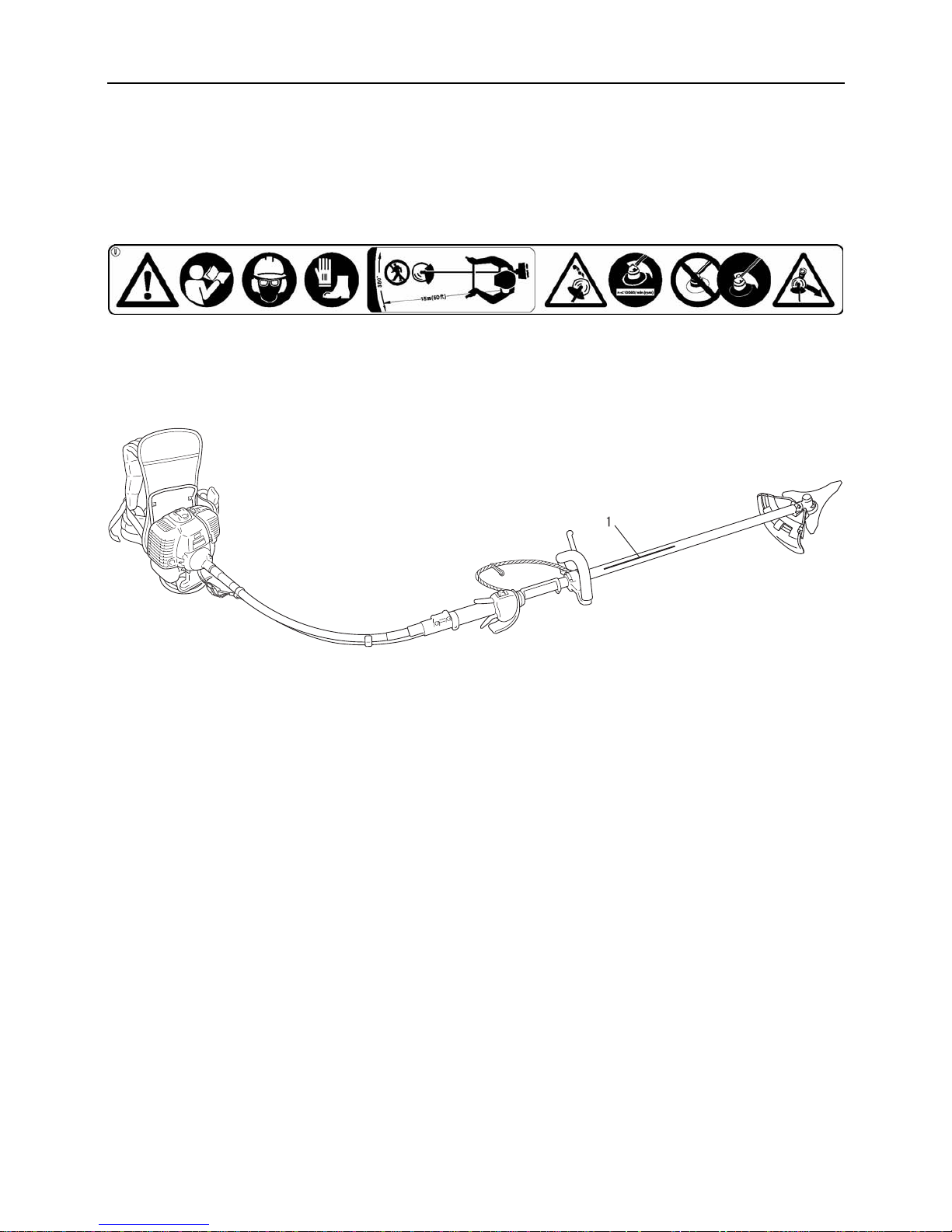
6
Sichere Verwendung des Produkts
Stelle, an der sich ein Sicherheitsaufkleber befindet
Die in dieser Anleitung beschriebenen Produkte sind mit de m u nte n d arge ste llten Sicherheitsaufkleber versehen. Machen Sie
sich die Bedeutung des Sicherheitsaufklebers bewusst, bevor Sie das Produkt verwenden.
Falls der Sicherheitsaufkleber aufgrund von Verschleiß oder Beschädigung nicht mehr lesbar ist oder sich abgelöst hat,
erwerben Sie bitte einen neuen Sicherheitsaufkleber von Ihrem ECHO-Händler, und bringen Sie ihn an der nach stehend
gezeigten Stelle an. Der Sicherheitsaufkleber muss stets gut lesbar sein.
1. Sicherheitsaufkleber (Teilenummer 890617-43130)
Page 53

7
Sichere Verwendung des Produkts
Umgang mit Kraftstoff
GEFAHR
Beim Auftanken in sicherer Entfernung von Brandherden bleiben
Kraftstoff ist leicht entflammbar und kann bei falschem Umgang schnell in Brand geraten. Gehen Sie beim Mischen,
Lagern und Betanken mit äußerster Vorsicht vor. Andernfalls kann es zu schweren Brandverletzungen kommen.
Befolgen Sie sorgfältig die folgenden Anweisungen.
Beim Betanken auf keinen Fall rauchen oder Feuer in die Nähe bringen.
Niemals betanken, während der Motor heiß ist oder läuft.
Andernfalls könnte sich der Kraftstoff entzünden und zu Verbrennungen führen.
Behälter und Ort des Betankens
Nur zugelassene Kraftstoffbehälter verwenden.
Kraftstofftanks und -kanister können unter Druck
stehen. Kraftstofftankdeckel immer langsam öffnen,
damit sich der Druck ausgleichen kann.
Kraftstofftanks NIEMALS in geschlossenen Räumen
befüllen. Kraftstofftanks IMMER im Freien und auf
sicherem Untergrund befüllen.
Verschütteter Kraftstoff ist feuergefährlich
Befolgen Sie beim Betanken folgende Sicherheitsregeln:
Füllen Sie den Tank nicht bis zur Einfüllöffnung auf.
Befüllen Sie den Tank nur bis zur vorgeschriebenen
Höhe (nur bis zum Ansatz des Einfüllstutzens).
Wischen Sie Kraftstoff, der aufgrund von Überfüllung
über- oder ausläuft, sofort auf.
Verschließen Sie den Kraftstofftankdeckel nach dem
Betanken wieder fest.
Verschütteter Kraftstoff kann sich entzünden und
Verbrennungen verursachen.
1. Kraftstofftank
2. Ansatz des Einfüllstutzens
Motor nicht am Ort der Betankung starten
Der Motor darf nicht an dem Ort gestartet werden, an
dem die Betankung stattfand. Bevor Sie den Motor
starten, entfernen Sie sich mindestens 3 m von der
Stelle, an der die Betankung erfolgte.
Beim Betanken übergelaufener
Kraftstoff kann sich leicht
entzünden.
Ausgetretener Kraftstoff stellt
eine Brandgefahr dar
Achten Sie nach dem Betanke n
stets darauf, dass aus der
Kraftstoffleitung, an den Kraftstoffdichtungen u nd rund
um den Kraftstofftankdeckel kein Kraftstoff austritt.
Sollten Sie feststellen, dass Kraftstoff austritt, stellen
Sie sofort die Verwendung des Produkts ein, und
wenden Sie sich an Ihren ECHO-Händler, um es
reparieren zu lassen.
Ausgetretener Kraftstoff stellt in jedem Fall eine
Brandgefahr dar.
Page 54

8
Sichere Verwendung des Produkts
Umgang mit dem Motor
WARNUNG
Starten des Motors
Befolgen Sie beim Starten des Motors unbedingt die
folgenden Sicherheitsregeln:
Überprüfen Sie, ob alle Schrauben und Muttern fest
angezogen sind.
Vergewissern Sie sich, dass nirgendwo Kraftstoff
ausgetreten ist.
Platzieren Sie das Produkt an einem ebenen, gut
belüfteten Ort.
Sorgen Sie für ausreichenden Abstand rund um das
Produkt, und lassen Sie keine Personen oder Tiere in
die Nähe.
Starten Sie den Motor mit dem Gashebel in der
Leerlaufstellung.
Halten Sie das Produkt beim Starten des Motors auf
dem Boden fest.
Eine Nichtbefolgung der Sicherheitsregeln kann zu
Unfällen, Verletzungen oder sogar zum Tod führen.
Nach dem Starten des Motors auf ungewöhnliche
Vibrationen oder Geräusche achten
Vergewissern Sie sich, dass nach dem Starten des
Motors keine ungewöhnlichen Vibrationen oder
Geräusche wahrzunehmen sind. Verwenden Sie das
Produkt nicht, wenn Sie ungewöhnliche Vibrationen
oder Geräusche feststellen. Wenden Sie sich an Ihren
ECHO-Händler, um es reparieren zu lassen.
Durch abfallende oder absplitternde Teile kann es zu
schweren Verletzungen kommen.
Während des Betriebs keine stark erhitzten oder
spannungsführenden Teile berühren.
Die folgenden stark erhitzten oder spannungsführenden
Teile des Produkts dürfen während des Betriebs und
einige Zeit danach nicht berührt werden:
Schalldämpfer, Zündkerze, Wink elgetriebe
und andere stark erhitzte Teile
Berührungen solcher stark erhitzter Teile
können zu Verbrennungen führ en.
Zündkerze, Zündkabel und andere
spannungsführende Teile
Sie könnten einen Stromschlag erleiden,
wenn Sie während des Betriebs ein
spannungsführendes Teil berühren.
Bei Feuer oder Rauch steht Sicherheit an erster
Stelle
Wenn Flammen aus dem Bereich des Motors kommen
oder Rauch aus einem anderen Teil als dem Auspuff
austritt, entfernen Sie sich zunächst von dem Produkt,
um Ihre eigene körperliche Sicherhe it zu gewäh rleisten.
Werfen Sie mit einer Schaufel Sand oder
ähnliches Material auf das Feuer, um eine
Ausbreitung zu verhindern, oder löschen
Sie den Brand mit einem Feuerlöscher.
Eine Panikreaktion könnte zu einer
Ausbreitung des Feuers oder anderen Schäden führen.
Auspuffgase sind giftig
Die Auspuffgase des Motors enthalten giftige
Substanzen. Betreiben Sie das Produkt nicht in
geschlossenen Räumen oder an anderen schlecht
belüfteten Orten.
Die Auspuffgase können zu Vergiftungen führen.
Schalten Sie den Motor ab, bevor Sie das Produkt
überprüfen oder warten
Beachten Sie die folgenden Sicherheitsregeln, wenn Sie
das Produkt nach der Verwendung überprüfen bzw.
warten:
Motor abschalten und Produkt erst überprüfen bzw.
warten, wenn der Motor abgekühlt ist
Andernfalls können Sie sich verbrennen.
Entfernen Sie den Zündkerzenstecker, bevor Sie
Überprüfungen und Wartungen durchführen.
Wenn das Produkt unerwarteterweise gestartet wird, kann
es zu Unfällen kommen.
Überprüfen der Zündkerze
Beachten Sie beim Überprüfen der Zündkerze die
folgenden Sicherheitsregeln:
Wenn die Elektroden oder Kontakte verschlissen sind
oder die Keramikteile Risse aufweisen, ersetzen Sie sie
durch neue Teile.
Die Funkenprüfung (zur Feststell ung, ob die Zün dkerze
einen Zündfunken wirft) muss von Ihrem ECHOHÄNDLER durchgeführt werden.
Die Funkenprüfung darf nicht in de r Nähe der
Zündkerzenöffnung durchgeführt werden.
Die Funkenprüfung darf nicht an Orten durchgeführt
werden, an denen verschütteter Kraftstoff oder
entflammbare Gase vorhand en sind.
Die Metallteile der
Zündkerze dürfen nicht
berührt werden.
Die Zündkerze kö nnte ein
Feuer entzünden oder
Ihnen einen elektrischen
Schlag versetzen.
Page 55

9
Sichere Verwendung des Produkts
Umgang mit dem Produkt
Allgemeine Sicherheitsregeln
WARNUNG
Bedienungsanleitung
Lesen Sie die Bedienungsanleitung vor
der Inbetriebnahme des Produkts
aufmerksam durch, um eine korrekte
Bedienung zu gewährleisten.
Andernfalls k ann es zu Unfällen
bzw.schweren Verletzungen kommen.
Produkt nur für den vorgesehenen Zweck
verwenden
Das Produkt darf nicht für andere als die in dieser
Bedienungsanleitung genannten Zwecke verwendet
werden.
Andernfalls kann es zu Unfällen bzw. schweren
Verletzungen kommen.
Keine Veränderungen am Produkt vornehmen
An dem Produkt dürfen keine Veränderungen
vorgenommen werden.
Andernfalls kann es zu Unfällen bzw. schweren
Verletzungen kommen. Funktionsfehler, die auf
Veränderungen am Produkt zurückzuführen sind, fallen
nicht unter die Herstellergarantie.
Produkt nur verwenden, wenn es überprüft und
gewartet wurde
Das Produkt darf nur verwendet werden, wenn es
überprüft und gewartet wurde. Die Überprüfung und
Wartung des Produkts muss regelmäßig durchgeführt
werden.
Andernfalls kann es zu Unfällen bzw. schweren
Verletzungen kommen.
Verleihen oder Übereignen des Produkts
Wenn Sie das Produkt verleihe n, muss die au sleihen de
Person auch die zugehörige Bedienungsanleitung
erhalten.
Wenn Sie das Produkt einer anderen Person
übereignen, muss die Bedienu ngsanleitung zusamme n
mit dem Produkt ausgehändigt w erden.
Andernfalls kann es zu Unfäl le n bzw. schw eren
Verletzungen kommen.
Vorsorge für den Fall von Verletzungen
Für den unwahrscheinlichen Fall, dass es dennoch zu
Verletzungen kommt, sollten Sie folgende Dinge
vorbereitet haben:
Verbandskasten
Hand- und Wischtücher (um etwaige Blutungen zu
stoppen)
Trillerpfeife oder Mobiltelefon (um Hilfe rufen zu
können)
Wenn Sie weder erste Hilfe lei sten noch Hilfe rufe n können,
kann sich die Verletzung verschlimmern.
Page 56
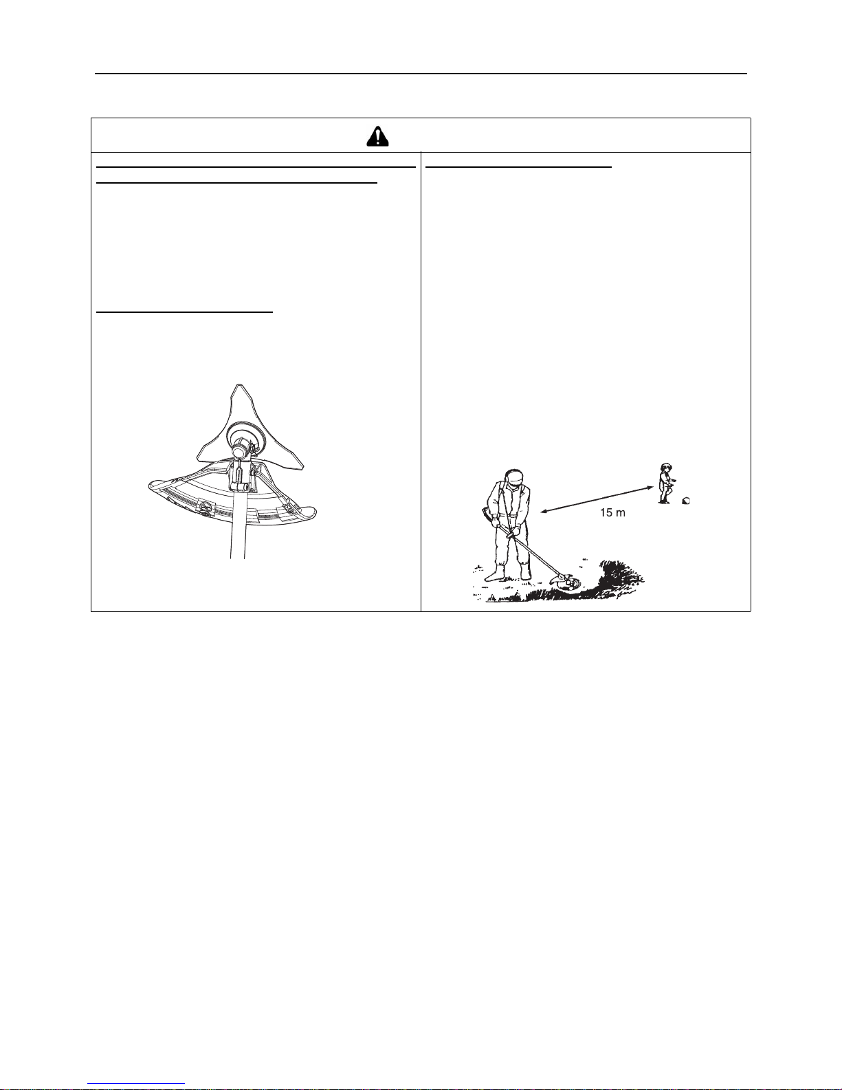
10
Sichere Verwendung des Produkts
Sicherheitsregeln für die Benutzung
GEFAHR
Produkt nicht verwenden, wenn sich das
Trimmermesser bei Leerlaufdrehzahl mitdreht
Das Produkt darf nicht verwendet werden, wenn sich
das Trimmermesser dreht, obwohl der Gashebel des
Rasentrimmers auf Leerlaufdrehzahl eingestellt ist.
Andernfalls kann es zu Unfällen bzw. schweren
Verletzungen kommen.
Schutzschild nicht entfernen
Verwenden Sie das Produkt niemals ohne den daran
befestigten Schutzschild.
Vom Trimmermesser abprallende Gegenstände können
Unfälle mit schweren Verletzungen verursachen.
Gefahrenzone im 15-m-Radius
Der Bereich in einem Radius von 15 m rund um dieses
Gerät gilt als Gefahrenzone. Beachten Sie bei der Arbeit
mit diesem Gerät folgende Sicherheitsregeln:
Lassen Sie keine Personen (insbe sondere Kinde r) oder
Tiere in die Gefahrenzone.
Sollte eine Person in die Gefahrenzone gelangen,
stellen Sie den Motor ab, so dass sich das Messer nicht
mehr dreht.
Wenn Sie sich dem Bediener näher n möchten,
signalisieren Sie ihm Ihre Absicht, indem Sie z. B.
Zweige von außerhalb der Gefahrenzone werfen, und
warten Sie dann, bis der Motor abgestellt wurde un d das
Messer stillsteht.
Wenn mehrere Personen mit dem Produkt arbeiten,
vereinbaren Sie eine Art der gegenseitigen
Kommunikation, und arbeiten Sie mit mindestens 15m
Abstand voneinander.
Vom Trimmermesser abprallende Gegenstände und
Kontakt mit dem Trimmermesser können zu Blindheit oder
tödlichen Unfällen führen.
Page 57

11
Sichere Verwendung des Produkts
WARNUNG
Benutzer des Geräts
Das Gerät darf von folgenden Personen nicht verwendet
werden:
übermüdeten Personen
alkoholisierten Personen
unter Medikamenteneinfluss stehenden Personen
schwangeren Frauen
Personen in schlechter
körperlicher Verfassung
Personen, die die
Bedienungsanleitung nicht
gelesen haben
Kindern
Eine Nichtbefolgung dieser
Anweisungen kann zu Unfällen führen .
Arbeitsumgebung und Bedienung
Verwenden Sie das Gerät nich t a n Or ten oh ne sic here n
Untergrund, etwa an steilen Hängen oder nach
Regengüssen, da solche Stellen rutschig und
gefährlich sind.
Verwenden Sie das Gerät nicht nachts od er an d unklen
Stellen mit schlechten Sichtverhältnissen.
Arbeiten Sie an leichten Hanglagen in horizontalen,
bogenartigen Bewegungen.
Wenn Sie fallen oder ausrutschen oder das Gerät nicht
mehr voll beherrschen, kann dies zu schw eren
Verletzungen führen.
Aus Gesundheits- und Sicherheitsgründen sollten Sie
mit dem Gerät nur bei Lufttemperaturen von – 5
o
C bis
40
o
C arbeiten.
Eine Nichtbefolgung dieser Anweisung kann zu
gesundheitlichen Schäden führen.
Motor beim Wechsel des Arbeitsorts abstellen
Wenn Sie sich in den unten b eschrieb enen Si tuationen an
eine andere Stelle bewege n, stell en Sie den Mo tor ab, un d
warten Sie, bis sich das Trimmer messer nich t mehr dreht.
Bringen Sie dann die Messerabde ckung an, und halten Sie
den Schalldämpfer von sich weg.
Sie suchen Ihren Arbeitsbereich auf
Sie wechseln im Verlauf der Arbeit den Arbeitsbereich
Sie verlassen Ihren bisherigen Arbeitsbereich
Bei Nichtbeachtung dieser Sicherheitsregeln können
Verbrennungen oder andere schwere Verletzungen die
Folge sein.
Zum Transport des Produkts in Kraftfahrzeugen
entleeren Sie seinen Kraftstofftank, bringen Sie die
Messerabdeckung an, und sichern Sie das Produkt so,
dass es nicht verrutschen kann.
Ein Transport des Pro dukts mit befülltem Kraft stofftank stellt
eine Brandgefahr dar.
Vibration und Kälte
Es wird vermutet, dass das Raynaud-Syndrom, das die
Finger mancher Menschen befä llt, du rch s t ark v ibriere nde
Arbeitsgeräte und dem Arbeiten bei Kälte herbeigeführt
wird. Durch stark vibrierende Arbeitsgeräte und dem
Arbeiten bei Kälte kann sich ein Prickeln und Brennen
bemerkbar machen, dem sich Farblosigkeit und
Gefühllosigkeit der Finger anschließen. Die nachstehend
aufgeführten Vorkehrungen werden dringend empfohlen,
da die Mindestwerte, bei denen diese Krankheit ausgelöst
wird, nicht bekannt sind.
Halten Sie Ihren Körper warm, insbesondere Kopf und
Nacken, Füße und Fußgelenke sowie Hände und
Handgelenke.
Legen Sie häufige Pausen ein, in dere n Verla uf Sie den
Kreislauf durch intensive Armübungen anregen, und
rauchen Sie nicht.
Begrenzen Sie die Dauerbetriebszeiten auf ein
Minimum. Teilen Sie je den Arbeitstag so ein, da ss auch
Arbeiten ohne Trimmer oder tragbare motorisierte
Geräte verrichtet werden.
Wenn Ihre Finger schmerzen, rot und angeschwollen
sind und schließlich bleich und gefühllos werden,
müssen Sie einen Arzt aufsuchen, bevor Sie sich
weiterhin Kälte und Vibrationen aussetzen.
Eine Nichtbefolgung dieser Anweisung kann zu
gesundheitlichen Schäden führen.
RSI-Syndrom
Es wird angenommen, dass eine Überanstrengung der
Muskeln und Sehnen der Finger, Hände, Arme und
Schultern in den betreffenden Körperteilen Schmerzen,
Schwellungen, Gefühllosigkeit, Schwäche und auch
akuten Schmerz verursachen kann. Durch bestimmte
ständig wiederholte Handbewegungen steigt das Risiko
für die Entwicklung eines RSI-Syndroms. Auf folgende Art
mindern Sie das Risiko des RSI-Syndroms:
Achten Sie darauf, dass Sie Ihr Handgelenk nicht zu
sehr beugen, strecken oder ve rdrehen.
Legen Sie von Zeit zu Zeit Pausen ein, um
Wiederholungsbewegungen z u minimieren, und la ssen
Sie Ihre Hände ruhen. Reduzieren Sie die
Geschwindigkeit und den Kraftaufwand, mit denen Sie
die Wiederholungsbewegung ausführen.
Führen Sie geeignete Übungen zur Stärkung der Hand-
und Armmuskulatur durch.
Suchen Sie einen Arzt auf, wenn Sie ein Prickeln,
Gefühllosigkeit oder Schmerzen in Ihren Fingern,
Händen, Handgelenken oder Armen bemerken. Je
früher das RSI-Syndrom erkannt wird, desto eher lässt
sich eine dauerhafte Schädigung von Nerven und
Muskeln verhindern.
Eine Nichtbefolgung dieser Anweisung kann zu
gesundheitlichen Schäden führen.
Angemessene Unterweisung
Das Gerät darf nicht ohne angemessene Unterweisung bzw. ohne Schutzkleidung bedient werden.
Machen Sie sich mit der richtigen Handhabung des Geräts und seiner Bedienungselemente vertraut.
Sie müssen wissen, wie sich das Gerät stoppen und der Motor abstellen lässt.
Zudem mussen Sie lernen, wie das Gerat schnell vom Schultergurt getrennt werden kann.
Erlauben Sie niemals einer anderen Person, das Gerät ohne vorherige Unterweisung zu benutzen.
Page 58

12
Sichere Verwendung des Produkts
WARNUNG
Vor dem Arbeiten mit dem Produkt alle Fremdkörper und
Hindernisse aus dem Arbeitsbereich entfernen
Bevor Sie mit der Arbeit beginnen, überprüfen Sie den Bereich, in dem
Sie arbeiten möchten, und entfe rnen Sie kl eine Stein e und lee re Dos en,
die durch die Schneidvorrichtung w eggeschleudert werden könnten,
sowie Schnüre oder Drähte , die sich um die Schneidv orrichtung wickeln
könnten.
Wenn Fremdkörper durch die Schneidvorrichtung weggeschleudert werden
oder sich Drähte o der andere M aterialien u m die Schne idvorrichtun g wickeln,
kann dies zu Unfällen bzw. schweren Verletzungen führen.
Schneidvorrichtung beim Arbeiten mit dem Produkt nicht nach oben halten
Halten Sie die Schneidvorric htun g wä hrend de s Arbeitens nicht nach oben. Die Schneidvorrichtung d arf n icht über
Kniehöhe angehoben werden.
Durch Anheben der Schneidvorrichtung über Kniehöhe würden Sie die Rotationsebene näher ans Gesich t bringen, und
Gegenstände, die von der Schneidvorrichtung weggeschleudert werden, könnten Unfälle bzw. schwere Verletzungen
verursachen.
Motor bei Problemen sofort abstellen
Stellen Sie den Motor in den nachfolgend genannten Situationen sofort ab, und vergewissern Sie sich, dass sich die
Schneidvorrichtung nicht mehr dreht. Überprüfen Sie dann die einzelnen Bereiche des Produkts. Ersetzen Sie
beschädigte Teile durch neue.
Die Schneidvorrichtung trifft beim Arbeiten auf einen Stein, Baum, Pfosten oder ein anderes Hindernis.
Das Produkt beginnt plötzlich, ungewöhnlich zu vibrieren.
Wenn beschädigte Teile weiter verwendet werden, kann dies zu Unfällen bzw. schweren Verletzungen führen.
Rückschlag
Wenn das Trimmermesser bei hoher Drehzahl auf ei nen
Baum, Pfosten, Stein oder einen anderen Gegenstand
trifft, prallt es urplötzlich heftig zurück. Dieses
Phänomen wird als Rückschlag bezeichnet.
Ein solcher Rückschlag kann bewirken, dass der
Bediener die Kontrolle über das Produkt verliert, und is t
deshalb höchst gefährlich.
Insbesondere, wenn das vordere rechte Viertel des
Trimmermessers (B) auf einen Busch oder ein anderes
Objekt trifft, wird das Produkt heftig nach rechts
zurückgeschleudert.
Um solche Rückschläge zu vermeiden, sollten Sie
niemals von links nach r echts trimmen. Achten Sie stet s
darauf, dass das Trimmermesser nicht auf harte
Gegenstände trifft.
Achten Sie beim Trimmen darauf, dass das zu
beschneidende Objekt vom vorderen Drittel der linken
Seite des Messers erfasst wird (A).
Andernfalls kann es zu Unfällen bzw. tödlichen
Verletzungen kommen.
Page 59

13
Sichere Verwendung des Produkts
Vorsichtsmaßnahmen zur Schneidvorrichtung
1.Bei Metallmessern
2.Bei Nylonfadenköpfen
GEFAHR
Stellen Sie den Motor sofort ab, wenn die Schneidvorr ichtung blockiert wird. Versuchen Sie nicht, einen Gegenstand
zu entfernen, solange der Motor läuft. Wenn die Blockade beseitigt wird und die Schneidvorrichtung plötzlich anläuft,
kann es zu schweren Verletzungen kommen.
WARNUNG
Die richtigen Messer verwenden
Bei falscher Verwendung der Messer drohen schwere
Verletzungen. Lesen und befolgen Sie alle
Sicherheitsanweisungen in dieser
Bedienungsanleitung.
Das 3-Zahn-Messer ist speziell zum Schneiden von
Unkraut und Gras vorgesehen. Um Verletzungen
aufgrund von Ruckschlag oder Klingenbruch zu
vermeiden, verwenden Sie das 3-Zahn-Messer nicht
zum Schneiden von Gestrupp oder Baumen.
Verwenden Sie nur von der KIORITZ CORPORATION
empfohlene Schneidvorrichtungen.
Beschädigte oder g ebroch ene Mes ser k önnen Un fälle bzw.
schwere Verletzungen verursachen.
Messer vor der Verwendung prüfen
Splitter eines gebrochenen Metallmessers können beim
Betrieb weggeschleudert werden. Überprüfen Sie
Metallmesser vor jeder Verwendung auf Bruchstellen.
Entfernen Sie gerissene Messer, egal, wie klein der Riss
ist. Gebrochene Messer können das Ergebnis von falscher
Verwendung oder unsachgemäßer Schärfung sein.
Beschädigte oder g ebroch ene Mes ser k önnen Un fälle bzw.
schwere Verletzungen verursachen.
Reaktionskräfte
Vergewissern Sie sich, dass Ihnen die in dieser
Bedienungsanleitung beschriebenen Reaktionskräfte –
Schub, Zug und Rückschlag – völlig klar sind und Ihnen
geläufig ist, wie sich diese Kräfte auf Ihr Gleichgewicht bei
der Bedienung des Geräts auswirken können.
Andernfalls kann es zu Unfällen bzw. tödlichen
Verletzungen kommen.
WARNUNG
Die richtige Schneidvorrichtung verwenden
Bei falscher Verwendung der Schneidvorrichtung
drohen schwere Verletzungen. Les en und befolg en Sie
alle Sicherheitsanweisungen in dieser
Bedienungsanleitung.
Verwenden Sie nur von der KIORITZ CORPORATION
empfohlene Schneidvorrichtungen.
Verwenden Sie nur Nylonfadenköpfe. Verwenden Sie
keinerlei Metallmesser.
Andernfalls kann es zu Unfäl le n bzw. sch w eren
Verletzungen kommen.
Nylonfäden, die über das Fadenschneidmesser
hinausragen, könnten weggeschleudert werden, wenn
sich der Fadenkopf nach der Anpassung der
Nylonfadenlänge zu drehen beginnt.
Bei Nichtbefolgung dieser Anweisung kann es zu Unfällen
bzw. Verletzungen kommen.
Keine Trimmarbeiten in der Nähe von Autos oder
Fußgängern durchführen
Seien Sie äußerst vorsichtig, wenn Sie an kahlen Stellen
oder auf Kiesflächen arbeiten, da der Faden kleine
Steinchen mit hoher Geschwindigkeit wegschleudern
kann. Der Schutzschild am Gerät hält kein e Objekte ab, die
von harten Oberflächen abprallen.
Andernfalls kann es zu Unfällen bzw. schweren
Verletzungen kommen.
Drahtstücke meiden
Nehmen Sie keine Trimmarbeiten an Orten vor, an denen
Stücke von Zaundraht herumliegen. Entfernen Sie die
Drahtstücke, oder meiden Sie den Bereich großräumig.
Tragen Sie eine geeignete Schut zausrüstung. Arbeiten Sie
nicht an Stellen, an denen Sie nicht sehen, was Sie
schneiden.
Andernfalls kann es zu Unfällen bzw. schweren
Verletzungen kommen.
Page 60
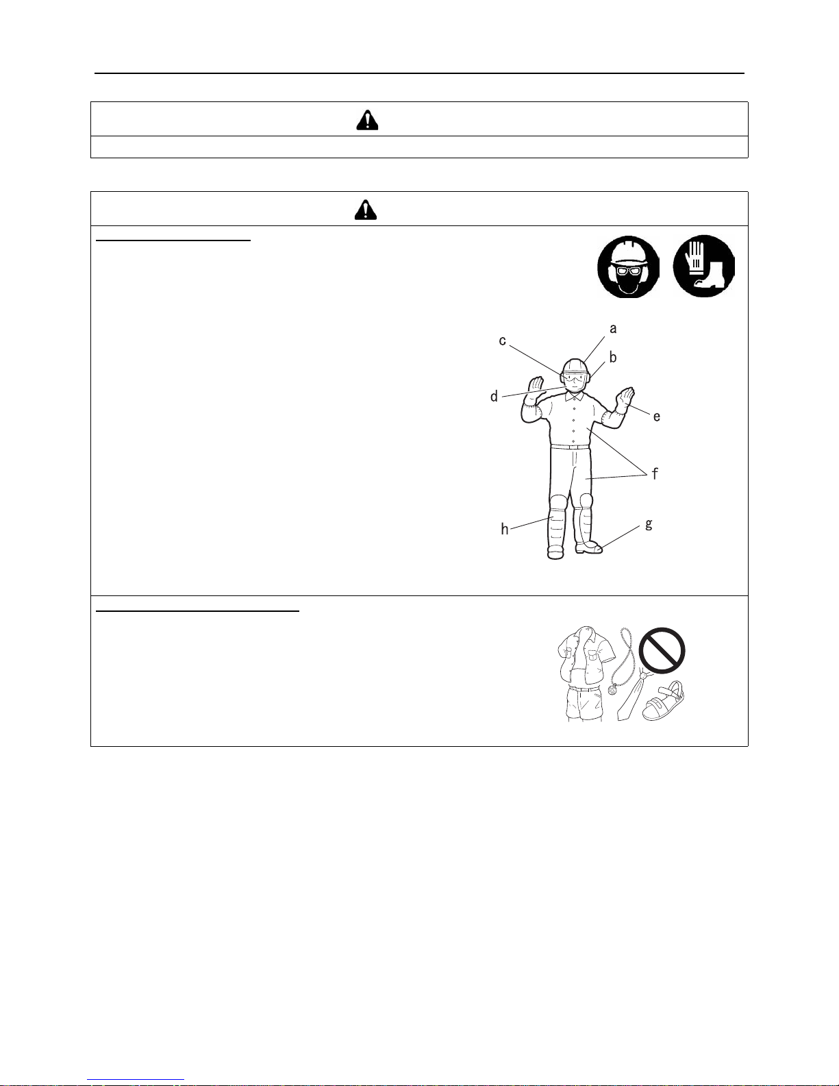
14
Sichere Verwendung des Produkts
Schutzausrüstung
VORSICHT
Verwenden Sie nur flexible, nichtmetallische, von der KIORITZ CORPORATION empfohlene Nylonfäden.
WARNUNG
Schutzausrüstung tragen
Tragen Sie beim Arbeiten mit dem Trimmer immer die
folgende Schutzausrüstung:
a Kopfsc hutz (Helm): schützt den Kopf
b Gehörschutzbügel oder Ohrenstöpsel: schützen das
Gehör
c Schutzbrille: schützt die Augen
d Gesichtsschutzschild: schützt das Gesicht
e Sicherheitshandschuhe: schützen die Hände vor Kälte
und Vibration
f Eng anliegende Arbeitskleidung (lange Ärmel, lange
Hosen): schützt den Körper
g Robuste, rutschfeste Stiefel (mit Schutzkappe) oder
rutschfeste Schuhe (mit Schutzkappe): schützen die
Füße
h Schienbeinschützer: schützen die Beine
Bei Nichtbeachtung di eser Sicherheitsvorkehrun gen sind Ihr
Augenlicht und Ihr G ehör gefährdet, u nd es drohen so nstige
schwere Verletzungen.
Falls erforderlich, verwenden Sie auch folgende
Schutzausrüstung:
Staubmaske: schützt das Atmungssystem
Bienennetz: schützt vor angreifenden Bienen
Geeignete Schutzkleidung tragen
Tragen Sie keine Krawatten, Schmuckstücke oder lose, weite
Kleidungsstücke, die sich im Gerät verfangen könnten. Tragen Sie keine
Schuhe mit freien Zehen, und arbeiten Sie nich t barfuß oder in kurzen Hosen.
In bestimmten Situationen kann ein Gesichts- und Kopf-Rundumschutz
erforderlich sein. Für das Schneiden von dichtem Gestrüpp mit
Metallmessern sind Waldarbei ter-Schutzhosen od er ähnliche Bekleidung mit
Schutzeinrichtung zu tragen.
Bei Nichtbeachtu ng dieser Sicher heitsvorkehrun gen sind Ihr Auge nlicht un d Ihr
Gehör gefährdet, und es drohen sonstige schwere Verletzungen.
Page 61
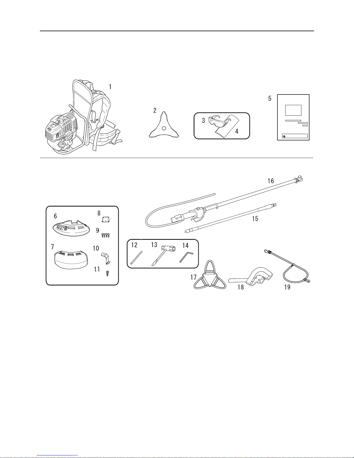
15
Packliste
Packliste
Die nachfolgend genannten Einzelteile sind in der Verpackung enthalten.
Überprüfen Sie nach dem Auspacken die Vollständigkeit des Inhalts.
Sollten Teile fehlen oder beschädigt sein, wenden Sie sich an Ihren ECHO-Händler.
Motor
Antriebswelle
1. Motor
2. 3-Zahn-Messer
3. Schutzbrille (gemäß ANSI Z 87.1)
4. Vorsichtshinweis
5. Bedienungsanleitung
6. Schutzschild (für Metallmesser)
7. Schutzschild (für Nylonfadenkopf)
8. Fixierungspunkt der Befestigungsplatte
9. Schraube M5x25
10. Fadenschneidmesse r
11. Schraube 5x12
12. Arretierwerkzeug
13. Steckschlüssel
14. Sechskant s chlüssel
15. Flexible Wellenbaugruppe
16. Antriebswellenrohr
17. Messerabdeckung
18. Vorderer Griff
19. Gurt
Page 62

16
Beschreibung
Beschreibung
1. Schneidvorrichtung 3-Zahn-Messer zum Schneiden
von Gras, Gartenabfällen und Unkraut.
2. Schutzschild Schützt den Bediener vor Kontakt mit dem
Schneidkopf und weggeschleuderten Objekten.
3. Winkelgetriebe Ermöglicht es, den Winkel der
Rotationsachse zu andern.
4. Antriebswellenrohr Gerätete il, das als Gehäuse für die
Antriebswelle dient.
5. Vorderer Handgriff Zur Schneidvorricht ung hin
angebrachter Handgriff.
6. Gurt Gummigurt zum Aufhängen der Antriebswelle.
7. Stoppschalter Schiebeschalter, der oben am Gehäuse
des Gashebels montiert ist. Schalter für den Betrieb
nach oben auf „RUN", zum Stoppen des Motors nach
unten auf „STOP" stellen.
8. Gashebel Regelt die Motordrehzahl und wird durch den
Bediener mit einem Finger betätigt.
9. Gashebelsperre Dient zum Arretieren des Gashebels im
Leerlauf, bis Sie mit der rechten Hand den Griff ganz
umgriffen haben.
10. Hinterer Handgriff Zum rück entragbaren Antriebsge rät
hin angebrachter Handgriff.
11. Flexible Wellenbaugruppe Biegsames Rohr für die
Antriebswelle.
12. Auspuffabdeckung Dient zum Schutz vor
versehentlicher Berührung mit dem heißen
Schalldämpfer.
13. Zündkerze
14. Luftfilterabdeckung Deckt den Luftfilter ab.
15. Kraftstofftank Enthält Kraftstoff und Kraftstofffilter.
16. Kraftstofftankdeckel Verschließt den Kraftstofftank.
17. Startergriff An diesem Griff ziehen, um den Motor zu
starten.
18. Messerabdeckung Verwenden Sie beim Transport des
Geräts die richtige Abdeckung für das Metallmesser.
Page 63

17
Bevor Sie beginnen
Bevor Sie beginnen
Zusammenbau
Flexible Wellenbaugruppe
Der erste Schritt beim Zusammenbau besteht darin, die
Antriebswellen (V) und (H) zu verbin den.
Lösen Sie die Schraube mit einem Sechskantschlüssel.
Schieben Sie die Antriebswelle (H) mit dem Abstandshalter
langsam und vollständig in die Hülse. - Die Hülse ist an der
Antriebswelle (V) angebra cht und befindet si ch im Inneren des
hinteren Griffs. - Der Abstandshalter am Ende der
Antriebswelle (H) verhindert ein Ablösen der Antriebswelle
(V).
Stecken Sie den Verbinder in den Halter, und ziehen Sie die
Schraube mit einem Sechskantschlüssel fest.
Der zweite Schritt besteht darin, die Antriebswelle (H) an den
Motor anzuschließen.
Drücken Sie den Arretierstift vollständig hinein, und stecken
Sie gleichzeitig das andere Ende der Antriebwelle (H) in die
Motorwelle. - Ziehen Sie für ein leichteres Anschließen die
Antriebswelle (H) vorher ca. 4 mm weiter heraus.
Stellen Sie nach dem Loslas sen des Arretierstifts sicher, dass
die flexible Welle nicht heraus gezogen werden kann und
richtig am Motor angeschlossen ist.
Gaszughalter-Baugruppe
Diese Baugruppe dient einer einfachen Verbindung und
Einstellung des Gaszugs.
Haken Sie das Zugseilende in das Kupplungsstück ein, und
schließen Sie die Abdeckung (A).
Verbinden Sie jeweils die Leitung (A) und die Leitung (B).
WARNUNG
Lesen Sie die Bedienungsanleitung aufmerksam durch, um sicherzustellen, dass Sie das
Produkt korrekt zusammenbauen.
Die Verwendung eines falsch zusammengebauten Produkts kann zu Unfällen bzw. schweren Verletzungen
führen.
1. Antriebswelle (V)
2. Halter
3. Antriebswelle (H)
4. Abstandshalter
5. Verbinder
6. Hülse
7. Schraube
1. Arretierstift
2. Schub
3. Antriebswelle (H)
1. Kupplungsstück
2. Zugseil
3. Halter
4. Leitung (A)
5. Leitung (B)
6. Gaszug
7. Abdeckung (A)
8. Abdeckung (B)
Page 64

18
Bevor Sie beginnen
Die Länge des innen verlaufenden Zugseils kann zur
Optimierung des Zieh ens angepasst wer den. Öffnen Sie daz u
die Abdeckung (B), und versetzen Sie den Flansch des
Gaszugs entsprechend nach links oder rechts in eine der
Nuten.
Die 2 Klemmen an der flexiblen Wellen baugruppe müssen an
geeigneten Stellen am Gaszug befestigt werden (im gleichen
Abstand über die Länge der flexiblen Wellenbaugruppe).
Rundgriff
Befestigen Sie den vorderen Griff und den Schutzhalter lose
am Antriebswellenrohr.
Stellen Sie den vorderen Griff auf eine bequeme Position ein.
Ziehen Sie die Schrauben (M5×35) und Muttern fest. - Eine
der 4 Schrauben muss wie abgebildet zusammen mit der
Hängescheibe festgezogen werden.
Schultergurt
Stellen Sie die L änge d es Rückentra gbands a uf komfort ablen
Sitz ein.
Da der Gurt elastisch und einstellbar ist, sollte er an den
Hängescheiben am vorderen Griff und dem linken oder
rechten Rückentragband angeschlossen werden, um einen
ermüdungsfreien und komfortablen Betrieb zu ermöglichen.
1. Abdeckung (A)
2. Abdeckung (B)
3. Gaszug
4. Zum Motor
5. Zur Kabeltülle
1. Klemme
2. Flexible
Wellenbaugruppe
3. Gaszug
1. Schraube M5×35
2. Vorderer Griff
3. Schutzhalter
4. Mutter
5. Hängescheibe
6. Antriebswellenrohr
1. Vorderer Griff
2. Hängescheibe
3. Gurt
Page 65

19
Bevor Sie beginnen
Montage des Schutzhalters
Befestigen Sie den Schutzhalter am Winkelgetriebe, indem Sie
die Befestigungsplatte von unten gegendrücken und die
4 Schrauben (M5×25) leicht anziehen.
Richten Sie die Kerbe und den Fixierpunkt der
Befestigungsplatte auf das entsprechende Gegenstück des
Schutzhalters aus, un d ziehen Sie die 4 Schrauben (M5×25) fest.
Es gibt zwei unterschiedliche Schutzschilde: Der eine
Schutzschild wird ausschließlich zur Verwendung des
Nylonfadenkopfes, der andere ausschließlich zur Verwendung
von Metallmessern angebracht. Wenn Sie mit Metallmessern
arbeiten, verwenden Sie den Schutzschild für Metallmesser.
Montage des Messers
Kontrollieren Sie das Messer vor der Montage. Überprüfen Sie
die Schärfe des Messers. Bei stumpfen Messern erhöht sich das
Risiko eines Rückschl ags . Klei ne R is se kö nne n sic h zu Brüc hen
entwickeln, so dass Tei le des Mess ers weggeschl eudert werden.
Entfernen Sie gerissene Messer, egal, wie klein der Riss ist.
Obere Druckplatte, Mes se r, untere Druckplatte und Auflageteller
zusammenstecken und Mutter handfest anziehen.
1. Schutzhalter
2. Schraube M5x25
3. Fixierungspunkt der
Befestigungsplatte
4. Befestigungsplatte
5. Fixierungspunkt der
Befestigungsplatte
1. Arretierungsloch der
Fixierplatte
2. Obere Druckplatte
3. Messer
4. Untere Fixierplatte
5. Auflageteller
6. Mutter
GEFAHR
Bei Verwendung von verschlissenen Muttern und
Auflagetellern zur Befestigung des Messers besteht die
Gefahr, dass sich das Messer lockert. Ersetzen Sie diese
Teile durch neue.
WARNUNG
Versuchen Sie nicht, das Trimmermesser mit einer
Hand oder ohne Verwendung des Steckschlüssels zu
montieren. Befestigen Sie das Trimmermesser
ordnungsgemäß mit dem mitgelieferten
Steckschlüssel, und ziehen Sie es in der richtigen
Position fest.
Wenn das Messer vibriert oder lose ist, darf der
Trimmer nicht verwendet werden.
Tragen Sie beim Arbeiten mit dem Trimmermesser
robuste Handschuhe. Wenn während eines
Trimmereinsatzes ein Trimmermesser ausgetauscht
werden muss, vergewissern Sie sich, dass der Motor
zuvor ausgeschaltet wurde und das Messer zum
Stillstand gekommen ist.
Wenn Sie das Produkt umdrehen, um das
Trimmermesser auszutauschen, achten Sie darauf,
dass der Kraftstofftankdeckel fest verschlossen ist.
Andernfalls kann es zu Unfällen, schweren Verletzungen
oder Bränden kommen.
Page 66

20
Bevor Sie beginnen
Stecken Sie das Arretierwerkzeug in das Loch auf der rechten
Seite des Winkelgetriebes. Drücken Sie dabei die
Rückhaltefeder nach links. Stecken Sie das Arretierwerkzeug in
das Arretierungsloch der Fixierplatte, um den
Werkzeugaufnahmebolzen zu blockieren.
Ziehen Sie di e Mu tt e r mi t ei nem S t ecks ch lü ss e l fe st ( geg e n d en
Uhrzeigersinn).
Niemals mit voller Kraft anziehen. Das Gewinde der Mutter
könnte beschädigt werden.
Ersetzen Sie die Mutter und den Auflageteller durch neue, egal,
wie gering die Abnutzung ist.
1. Messer 2. Arretierwerkzeug
VORSICHT
Verhindern Sie mit Hilfe des Arretierwerkzeugs ein
Mitdrehen des Werkezeuga ufnahmebolzens während der
Montage. Andernfalls kann die Mu tter zur Befestigung de s
Messers nicht ausreichend festgezogen werden.
1. Steckschlü ssel 2. Messer
Page 67
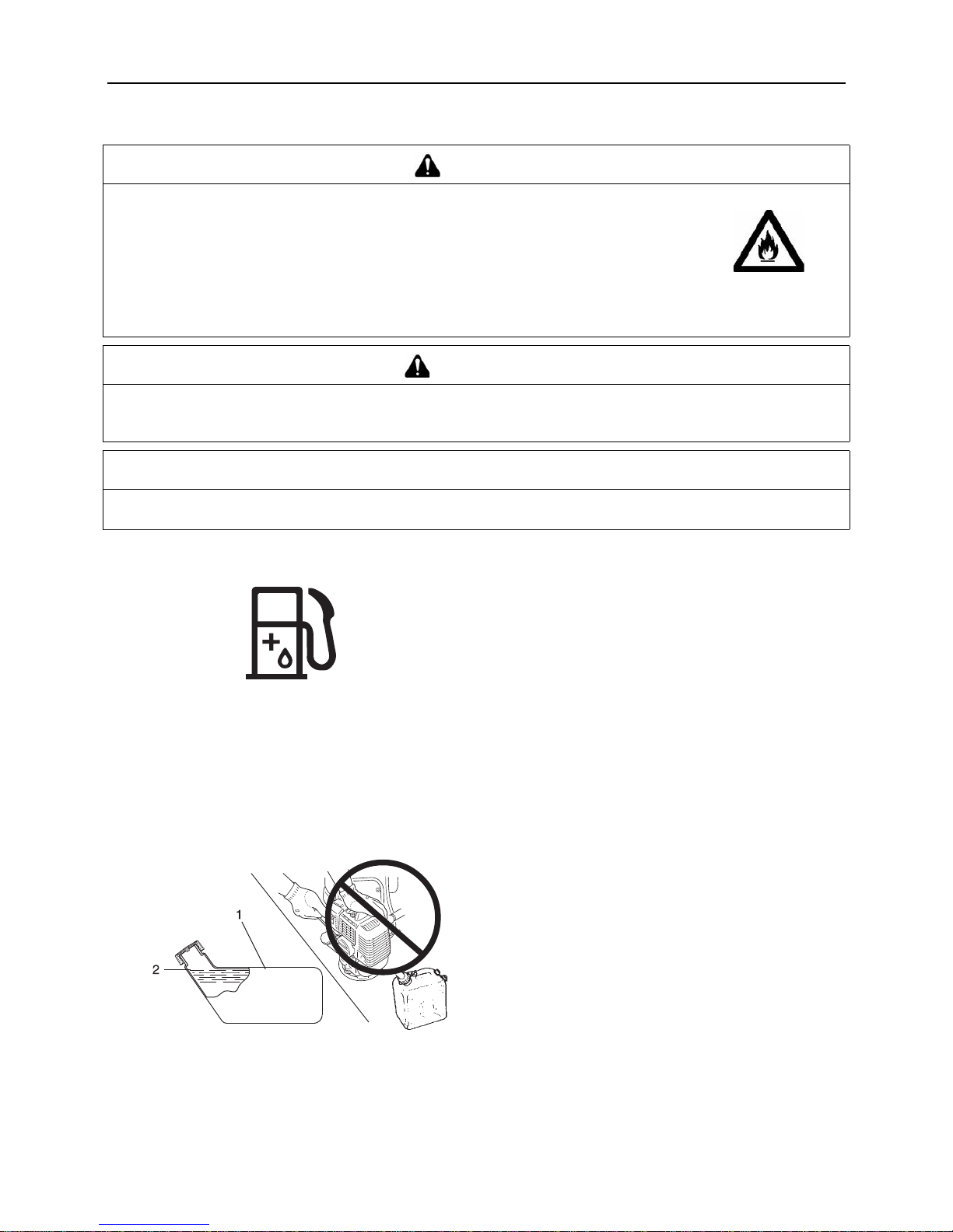
21
Bevor Sie beginnen
Bereitstellen des Kraftstoffs
Kraftstoff
Der Kraftstoff ist ein Gemisch aus Normalbenzin und
hochwertigem Markenöl für luftgekühlte Zweitaktmotoren.
Verwenden Sie bleifreies Benzin mit mindestens 89 Oktan.
Verwenden Sie keinen Kraf tstoff mit Methy lalkoho l oder mehr
als 10 % Ethylalkohol.
Empfohlenes Mischverhältnis: 50 : 1 (2%) Öl nach ISO-L-
EGD Standard (ISO/CD 13738), JASO FC, FD und ECHO
Premium 50: 1 Öl.
- Mischen Sie den Kraftstoff nicht direkt im MotorKraftstofftank.
- Achten Sie darauf, dass kein Benzin oder Öl verschüttet
wird. Wischen Sie verschütteten Kraftstoff stets auf.
- Gehen Sie mit Benzin vorsichtig um. Es ist äußerst leicht
entzündlich.
- Lagern Sie Benzin nur in zugelassenen Behältern.
Kraftstoffversorgung
Führen Sie die Betankung nur an gut belüfte ten Orten durch.
Füllen Sie Kraftstoff niemals in Innenräumen ein oder um.
Platzieren Sie das Produkt und den Befüllungskanister
während des Betankens auf dem Boden. Führen Sie die
Betankung nicht auf der Ladefläche vo n Lkws oder an
ähnlichen Orten durch.
Achten Sie beim Betanken stets darauf, dass der Füllstand
den Ansatz des Einfüllstutzen s nic ht übe rste igt .
Im Kraftstofftank und in der Umgebungsluft herrschen
unterschiedliche Drü ck e. Lösen Sie deshalb zum Betanken
den Tankdeckel zunächst nur leicht, um die Druckdifferenz
auszugleichen.
Wischen Sie verschütteten Kraftstoff sofort auf.
Bevor Sie den Motor starten, entfernen Sie sich mindestens
3 m von der Stelle, an der di e Betankung durchgef ührt wurde.
Bewahren Sie den Befüllun gskanister an einem schattigen Ort
in weiter Entfernung von Brandquellen auf.
GEFAHR
Kraftstoff ist leicht entflammbar und kann bei falschem Umgang schn ell in Brand gerat en.
Lesen und befolgen Sie die Sicherheitsanweisungen im Abschnitt „Sichere Verwendung
des Produkts" in dieser Bedienungsanleitung.
Nachdem Sie den Tank mit Kraftstoff befüllt haben, schraube n Sie den Tankd eckel fes t zu,
und stellen Sie sicher, dass aus der Kraftstoffleitung, an den Dichtungen und im Bereich
des Tankdeckels kein Kraftstoff austritt. Sollten Sie feststellen, dass Kraftstoff austritt,
stellen Sie sofort die Verwendung des Produkts ein, und wenden Sie sich an Ihren ECHOHändler, um es reparieren zu lassen.
Eine Entzündung des Kraftstoffs kann zu Verbrennungen und Bränden führen.
VORSICHT
Im Kraftstofftank und in der Umgebungsluft herrsche n unterschi edliche Drüc ke. Lösen Sie deshalb zum Betanken de n
Tankdeckel zunächst nur leicht, um die Druckdifferenz auszugleichen.
Andernfalls kann es vorkom m en, das s Kraftstoff herausspritzt.
HINWEIS
Gelagerter Kraftstoff altert. Mischen Sie nic ht mehr Kraftstoff an , als Sie voraussic htlich innerhalb der n ächsten dreißig (30) Tage
verbrauchen werden. Mischen Sie den Kraftstoff nicht direkt im Kraftstofftank .
1. Kraftstofftank 2. Ansatz des
Einfüllstutzens
Page 68

22
Bedienung des Motors
Bedienung des Motors
Starten des Motors
Starten eines kalten Motors
(Stecken Sie den Zündkerzenstecker wieder auf, wenn das
Produkt lange Zeit nicht benutzt wurde.)
Beim Starten kommt es darauf an, ob der Motor kalt oder warm
ist. Gehen Sie bei einem kalten Motor folgendermaßen vor:
1. Entfernen Sie die Trimmermesserabdeckung und
überprüfen Sie das Trimmermesser. Falls es Schäden
aufweist, ersetzen Sie es durch ein neues.
2. Legen Sie das Produkt flach auf den Boden, und so rgen Sie
durch Unterlegen eines Balkens oder eines ähnlichen
Hilfsmittels dafür, das s das Messer ni cht den Boden be rührt.
3. Vergewissern Sie sich, dass nirgendwo Kraftstoff austritt.
4. Stellen Sie den Zündsc halter auf „Start".
5. Stellen Sie sicher, dass sich der Gashebel in der
Leerlaufstellung befindet.
6. Stellen Sie den Chokeknopf auf die Position „Kaltstart".
7. Betätigen Sie die Kraftstoffpumpe so oft (drücken und
loslassen), bis sie Kraftstoff angesaugt hat.
WARNUNG
Beachten Sie beim Starten des Motors die Sicherheitsanweisungen ab Seite 4 im Abschnitt „Sichere Verwendung
des Produkts", um eine einwandfreie Bedienung des Geräts sicherzustellen.
Wenn sich die Schneidvorrichtung beim Starten dreht, obwohl der Gashebel auf Leerlaufdrehzahl eingestellt ist,
justieren Sie den Vergaser nach, bevor Sie das Produkt verwenden.
Eine Nichtbefolgung der Sicherheitsregeln kann zu Unfällen, Verletzungen oder sogar zum Tod führen.
HINWEIS
Ziehen Sie den Star tergriff zuers t lan gsam un d dan n a llmählic h sc hnell er hera us. Zi ehen Sie da s Starterse il hö chste ns au f 2/
3 seiner Länge heraus.
Lassen Sie den Startergriff beim Zurückschnellen nicht los.
1. Zündschalter
2. Gashebel
3. Gashebelsperre
1. Kraftstoffpumpe
2. Chokehebel
3. Kaltstart (CLOSE)
4. Betrieb (OPEN)
5. Startergriff
Page 69

23
Bedienung des Motors
8. Nachdem Sie die Sicherheit des Ortes überprüft haben,
halten Sie das Gerät möglichst nahe am Motor (siehe
Abbildung), und ziehen Sie mehrmals am Startergriff.
9. Falls Sie ein explosionsartiges Geräusch hören und der
Motor sofort still steht, st ellen Sie den Chok eknopf a uf „Run"
(Betrieb), und ziehen Sie wiederholt am Startergriff, um den
Motor zu starten.
10. Falls der Motor beim Ausführen von Schritt 8 (siehe oben)
sofort anspringt, stellen Sie den Chokehebel langsam
wieder auf „Run" (Betrieb).
11. Lassen Sie den Motor eine Weile im Leerlauf warmlaufen.
Warmlaufen des Motors
1. Sobald der Motor läuft, lassen Sie ihn 2 bis 3 Minuten im
Leerlauf (niedrige Drehzahl) warmlaufen.
2. Das Warmlaufen des Motors sorgt für eine gleichmäßigere
Schmierung im Inneren. Lassen Sie den Motor vollständig
warmlaufen, insbesondere bei Kälte.
3. Lassen Sie den Motor niemals ohne Schneidvorrichtung
laufen.
Starten eines warmen Motors
1. Stellen Sie den Zündsc halter auf „Start".
2. Stellen Sie sicher, dass sich der Gashebel in der
Leerlaufstellung befindet.
3. Stellen Sie sicher, dass sich der Chok ehebel in der Posi tion
„Run" (Betrieb) befindet.
4. Sofern Kraftstoff im Tank vorhanden ist, ziehen Sie am
Startergriff, um den Motor zu starten.
5. Ist kein Kraftstoff in der Kraftstoffpumpe sichtbar, betätigen
Sie die Kraftstoffpumpe so oft (drücken und loslassen), bis
sie Kraftstoff angesaugt hat.
6. Nachdem Sie Ihre unmittelbare Umgebung auf Sicherheit
überprüft haben, halten Sie das Gerät möglichst nahe am
Motor, und ziehen Sie am Startergriff, um den Motor zu
starten.
1. Zündschalter
2. Gashebel
3. Gashebelsperre
1. Kraftstoffpumpe
2. Chokehebel
3. Kaltstart (CLOSE)
4. Betrieb (OPEN)
5. Startergriff
Page 70

24
Bedienung des Motors
Stoppen des Motors
1. Stellen Sie den Gashebel in die Leerlaufposition, u nd lassen
Sie den Motor bei Leerlaufdrehzahl (niedrige Drehzahl)
laufen.
2. Stellen Sie den Zündsc halter in die Position „Stopp".
3. Stoppen Sie den Motor im Notfall sofort mit Hilfe des
Zündschalters.
4. Falls der Motor dadurch nicht gesto ppt wird, bringen Si e den
Chokehebel in die Position „Kaltstart". Der Motor wird
„abgewürgt" und dadurch angehalten (Not-Aus).
∗ Wenn sich der Motor mit dem Stoppschalter nicht stoppen
lässt, lassen Sie den Zündschalter von Ihrem ECHO-Händler
überprüfen und reparieren, bevor Sie das Produkt erneut
verwenden.
Wenn Sie mit der Arbeit fertig sind oder das Gerät
vorübergehend beiseite legen wollen, trennen Sie stets das
Zündkabel von der Zündkerze, damit der Motor nicht von
Unbefugten gestartet werden kann.
1. Zündschalter 2. Gashebel
1. Zündkabel 2. Zündkerze
Page 71

25
Trimmen
Trimmen
Versuchen Sie nie, das Produkt mit nur einer Hand zu
bedienen.
Halten Sie die Griffe immer so, dass sie von Daumen und
übrigen Fingern fest umschlossen sind.
1. Halten Sie den hinteren G riff d es An triebswe llenro hrs i n der
linken Hand, und hängen Sie sich das rechte
Rückentragband über die rechte Schulter.
2. Halten Sie den hinteren G riff d es An triebswe llenro hrs i n der
rechten Hand, und hängen Sie sich das linke
Rückentragband über die linke Schulter.
3. Bewegen Sie das Gerät ein paar Mal hin und her, um eine
gleichmäßige Belas tun g b eider Schulterseiten zu erreichen.
4. Schließen Sie den Gurt vorzugsweise an den
Hängescheiben am Rundgriff am linken und rechten
Rückentragband an, un d stellen Sie die Länge des Gurts auf
komfortablen Betrieb passend ein.
Erhöhen Sie nach Bedarf di e M ot ordre hz ahl ; d as Sc hne ide n von
kräftigem Unkraut erfordert mehr Leistung als das Mähen von
Gras. - Kleine Bäume oder dichtes Buschwerk können mit der
Kreissäge geschnitten we rden. - Das 3-Zahn-M esser dar f nur für
das Schneiden von Gras, Buschwerk oder dichtem Unkraut
verwendet werden.
Halten Sie den vorderen Griff (Rundgriff) und den hinteren Griff
mit beiden Händen.
Beim Schneiden von Unkraut oder Gras schwingen Sie das
Messer in einem Bogen von einer Seite zur anderen und
gehen dabei vorwärts.
Das Messer dreht entgegen dem Uhrzeigersinn. Sie müssen
also die Pflanzen von rechts nach links scheiden.
So sollten Sie gehen: - Setzen Sie den rechten Fuß vor den
linken Fuß. - Schreiten Sie erst mit dem re chten Fuß vorwärts ,
und achten Sie auf einen sicher en Stand. - Dann schreiten Sie
mit dem linken Fuß hinter den rechten.
Achten Sie darauf, ni cht gegen Hindernisse zu stoßen, wie
Steine oder Baumstümpfe, die das Messer beschädigen
könnten. - Im Falle, dass das Messer gegen ein Hindernis
stößt oder auf andere Weise am normalen Drehen gehindert
wird, rutscht die Kupplung durc h, um ein en Moto rsc ha den zu
verhindern. - Stellen Sie in diesem Fall den M otor ab, befrei en
Sie das Messer, und nehme n Sie da nac h den Betrie b w ied er
auf.
Schneiden Sie nicht in den Boden.
Betreiben Sie das Gerät nicht ohne Last bei Vollgas, da das
den Motor beschädigen kann.
GEFAHR
Stellen Sie den Motor sofort ab, wenn die Schneidvorr ichtung blockiert wird. Versuchen Sie nicht, einen Gegenstand
zu entfernen, solange der Motor läuft. Wenn die Blockade beseitigt wird und die Schneidvorrichtung plötzlich anläuft,
kann es zu schweren Verletzungen kommen.
Page 72
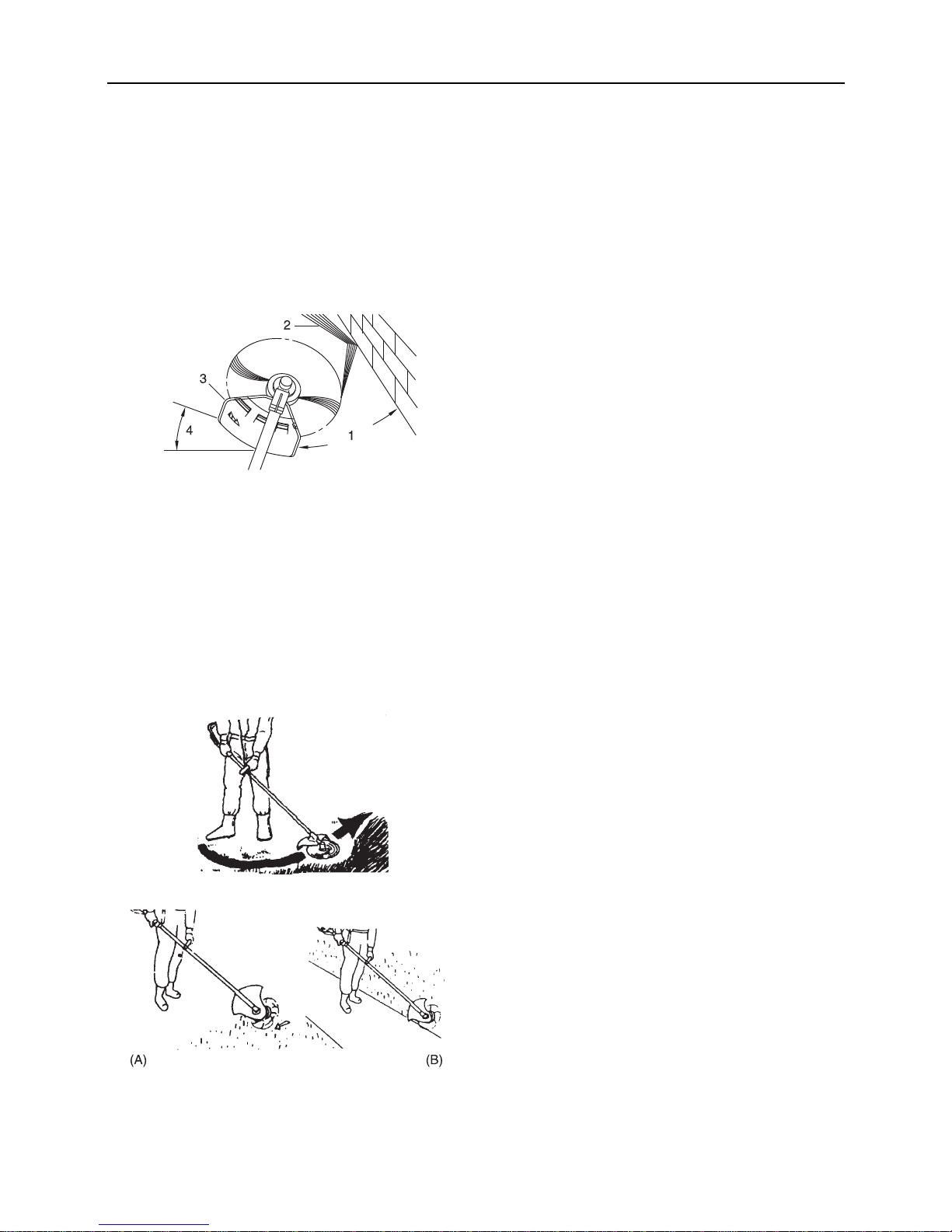
26
Trimmen
Wenn das Gerät über eine längere Zeit bei hohen
Temperaturen betrieben wird, kann das Winkelgetriebe sehr
heiß werden. Wenn es zu heiß für Berührung ist, lassen Sie
das Gerät abkühlen, kontrollieren Sie das Schmiermittel
entsprechend der Anlei tung, und setz en Sie dann den Be trieb
fort, sofern alles in Ordnung ist.
Einfaches Trimmen mit dem Nylonfadenkopf
Mögliche Schneidvorgänge
Nachstehend sind folgende Schneidvorgänge dargestellt:
Trimmen, Mähen, Skalpieren und Kantenschneiden.
Diese Vorgänge werden folgenderm aß en ausgeführt:
Trimmen
Hierbei wird der Trimmer vorsichtig an das zu schneidende
Material herangeführt. Stellen Sie den Fadenkopf etwas schräg,
damit das Schneidgut von Ihnen weggeleitet wird. Arbeiten Sie
sich beim Schneiden i n Richtu ng eines Hin dernisse s (z. B. Zaun,
Mauer oder Baum) in einem Winkel vor, bei dem sichergestellt
ist, dass vom Hindernis abprallendes Schneidgut von Ihnen
weggeleitet wird.
Bewegen Sie den Nylonfadenkopf langsam, bis das Gras bis
zum Hindernis ab gemäht ist, da bei aber der Faden d as Hindernis
nicht berührt. Wenn Sie Trimmarbeiten entlang eines
Maschendraht- oder Kettengliedzauns durchführen, so achten
Sie darauf, dass Sie das Gerät nur bis zum Zaundraht führen.
Ansonsten kann der Faden beim Auftreffen auf den Zaundraht
reißen.
Beim Trimmen können Unkrauthalme nacheinander
durchgeschnitten werde n. Setzen Sie den Nylonfadenkopf immer
am unteren Bereich der Pflanze an, da sich die Pflanze sonst
evtl. nur beugt und wieder aufrichtet und sich im Nylonfaden
verfangen könnte. Anstatt das Un kraut so fort durc hzus chnei den,
führen Sie das Ende des Nylonfadens allmählich durch den
Unkrauthalm.
Mähen
Hierbei werden große Grasflächen durch Schwingen des
Trimmers in e inem horiz ontalen Bo gen gemäht. Arbeiten Sie in
gleichmäßigen, ruhigen Bewegungen. Versuchen Sie nicht, das
Gras durch Hackbewegungen zu schneiden. Kippen Sie den
Nylonfadenkopf so, dass das gemähte Gras von Ihnen weg auf
die bereits gemähte Fläche ge worfen wird. Dann – oh ne Gras zu
schneiden – das Gerät zurückführen, um den nächsten Bogen
auszuführen. Wenn Sie gut geschützt sind und es Ihnen nichts
ausmacht, wenn Schneidgut auf Sie zugeschleudert wird,
können Sie in beide Richtungen mähen.
Skalpieren und Kantenschnei den
Beides wird durchgefü hrt, indem der Nylo nfadenkopf stei l gekippt
wird. Beim Skalpieren wird die Vegetation so weit geschnitten,
dass nur der kahle Boden zurückbleibt. Beim Kantenschneiden
wird das Gras an St ellen zurückgetrim mt, an denen e s über einen
Fußgängerweg oder eine Zufahrt gewachsen ist. Sowohl beim
Kantenschneiden als auch beim Skalpieren ist das Gerät in
einem steilen Winkel so zu halten, dass das Schneidgut sowie
sich aus dem Boden lösende Steine und Schmutz nicht auf Sie
zugeschleudert werden.
Wenngleich das Kantenschneiden und Skalpieren hier in einer
bestimmten Weise abge bi lde t sind, muss jeder Bediener für sich
selbst gemäß seiner Körpergröße den Winkel herausfinden, in
dem er besten arbeiten kann.
1. Winkel zur Wand
2. Schneidgut
3. Schräg gestellte
Schneidvorrichtung
4. Winkel zum Boden
A: Skalpieren B: Kantenschneiden
Page 73

27
Trimmen
Bei fast allen Schneidarbeiten empfiehlt es sich, den
Nylonfadenkopf so schräg zu stellen, dass der Kontakt in dem
Teil des Schneidkreises erfolgt, wo der Nylonfaden sich von
Ihnen und dem Schutzschild wegbewegt (siehe Abbildung).
Dadurch wird das Schneidgut von Ihnen weggeleitet.
Wenn Sie den Fadenkopf zur falschen Seite neigen, wird das
Schneidgut auf Sie zugeschleudert. Wenn der Nylonfadenkopf
flach gegen den Boden gehalten wird, so dass der
Schneidvorgang über den gesamten Schneidkreis erfolgt, wird
das Schneidgut auf Si e zuges chleudert, di e Motordre hzahl du rch
den Widerstand verringert, und es wird sehr viel mehr
Nylonfaden verbraucht.
Tragen Sie zum Schutz vo r hoc h g esc hl eud erte n G eg ens tän den
stets geeigneten Augenschutz. Gegenstände können vom
Boden her unterhalb des Schutzschildes hochschnellen oder von
nahe gelegenen Objekten zurückprallen.
Verwenden Sie den Trimmer nicht mit hohen Drehzahlen an
verkehrsreichen Straßen oder in der Nähe von Fußgängern.
Wenn es sich nicht verm eiden lässt, dass Sie dort arbeiten, wo
sich in der Gefahrenzone Menschen befinden, drücken Sie den
Gashebel nur leicht. Arbeiten Sie nicht mit Vollgas.
Lassen Sie den Nylonfadenkopf nicht in zähes Unkraut, Bäume
oder Zäune eindringen.
Wenn der Nylonfaden in Maschendraht, Zäune oder dichtes
Gestrüpp eindringt, kann es passieren, dass abgerissene
Fadenstücke gegen den Bediener geschleudert werden. Am
besten arbeiten Sie sich so weit wie möglich an das jeweilige
Hindernis heran, ohne den Nylonfaden in das Hindernis
vordringen zu lassen. Schneiden Sie nicht direkt an einem
Hindernis.
Achten Sie darauf, dass der Nylonfaden nicht mit beschädigtem
Zaundraht in Berührung kommt. Durch den Trimmer
abgebrochene Drahtstücke können mit hoher Geschwindigkeit
durch die Luft geschleudert werden.
Nylonfadenkopf dreht sich gegen den
Uhrzeigersinn. Das Fadenschneidmesser befindet
sich links am Schutzschild.
1. Schneidgut
2. Auf dieser Seite schneiden
1
2
Führen Sie keine Trimmarbeiten in der Nähe von
Autos oder Fußgängern durch.
Wenn sich der Nylonfaden in einem Drahtzaun
verfängt, reißt er.
Drahtstücke meiden
Page 74

28
Trimmen
Einfaches Trimmen mit Metallmesser
Verwendung des richtigen Messers
Verwenden Sie stets das für die Aufgabe geeignete Messer.
Verhindern Sie, dass der Trimmer harte Gegenstände wie
Steine, Beton oder Metall berührt.
Lassen Sie das Messer nicht den Erdboden berühren.
Falls das Mess er auf eine n harten Ge genst and trifft, schalte n
Sie den Motor sofort ab, warten Sie, bi s das Mess er stil lsteht ,
und überprüfen Sie dann das Messer und den Schutzschild
auf etwaige Beschädigungen.
Arbeiten Sie nicht mit einem stumpfe n, verb oge ne n,
gebrochenen oder verfärbten Me ss er und nic ht mi t einer
verschlissenen oder beschädigten Befestigungsmutter.
Verwenden Sie niemals Messer mit Rissen, da Teile des
Messers beim Arbeiten weggeschleudert werden könnten.
Lassen Sie den Motor niemals ohne Last mit Vollgas laufen.
Entfernen Sie alle Fremdkörper aus dem Arbeitsbereich.
Betreiben Sie die Motorsense nur mit Schutzschild.
Unkraut mähen
Beim Mähen wird die Schneidvorrichtung in einem horizontalen
Bogen geschwungen. Dad urch lassen sich große Berei che rasch
von Gras und Unkraut befreien. Die Sensenmethode eignet sich
jedoch nicht zum Mähen von hohem, zähem Unkraut oder
holzhaltiger Vegetation.
Wenn sich im Messer ein Schößling oder eine Staude verfängt,
darf das Gerät nicht als He bel benu tzt werden, um die Pf lanze zu
entfernen, da die Schneidvorrichtung dadurch beschädigt
werden würde.
Schalten Sie stattdessen den Motor ab, und entfernen Sie,
nachdem das Messer zum Stillstand gekommen ist, den
Schößling bzw. die Staude vom Messer.
Verwenden Sie kein Messer mit Rissen oder anderen
Beschädigungen.
WARNUNG
Befolgen Sie beim Trimmen die folgenden Anweisungen:
Achten Sie darauf, dass der Trimmer keine harten Gegenstände wie Steine, Metall oder Beton berührt.
Falls das Messer auf einen solchen Gegenstan d trifft, schalten Sie den Motor sofort ab, warten
Sie, bis das Messer stillsteht, und überprüfen Sie dann das Messer und den Schutzschild auf
etwaige Beschädigungen.
Verwenden Sie niemals Messer mit Rissen, da Teile des Messers beim Arbeiten
weggeschleudert werden könnten.
Vergewissern Sie sich, dass die Befestigungsmutter des Messers fest angezogen ist.
Wenn der Schutzschild beschädigt oder gerissen ist, ersetzen Sie ihn durch einen neuen.
Ersetzen Sie die Befestigungsmu tter des Trimmermessers, wenn sie Verschleißspuren aufweist.
Andernfalls kann es zu Unfällen bzw. schweren Verletzungen kommen.
Überprüfen Sie das Messer vor der Verwendung.
Drähte können sich verfangen und zu Peitschen
werden.
Page 75

29
Trimmen
Reaktionskräfte
Schub.
Der Bediener stellt u. U. fest, dass sich das Gerät auf ihn
zuschiebt, wenn er versucht, das Objekt mit der rechten
Messerseite zu schneiden. Wenn er das Messer nicht in der
Schnittfläche halten kann, könnte sich ein Rückschlag ergeben,
wenn das Messer das Objekt dort berührt, wo die Zähne in
größter Entfernung vom Bediener schneiden. Das Messer
schlägt dann seitwärts aus.
Zug.
Das Gegenteil von Schu b. Wenn sich das O bjekt links v om Gerät
befindet, stellt der Bediener u. U. fest, dass das Gerät von ihm
weggezogen wird. Obwohl bei dieser Methode Sägespäne
gegen den Bediener geworfen werde n können, empfie hlt sie sich
zum Sägen von hartem Gestrüpp, da dieser Schneidvorgang
gleichmäßiger und stabiler abläuft als das Schneiden mit
Schubwirkung.
Rückschlag.
Wenn Sie mit dem vorderen rechten Bereich des
Trimmermessers auf einen harten Gegenstand stoßen, etwa
beim Trimmen in bei de Rich tungen, wird das Messer heftig nach
rechts zurückgeschlagen. Diese Wirkung wird als „Rückschlag"
bezeichnet. Sie kann zu schweren Unfällen führen, da der
Bediener u. U. die Kontroll e über das Produkt ver liert. Achten Sie
besonders darauf, dass Sie mit dem vorderen rechten Bereich
des Trimmermessers nicht auf harte Gegenstände stoßen.
Sicherheitsregeln bei der Arbeit
Ein Bereich im Radius von 15 m um das Produkt gilt als
Gefahrenzone. Vergewis sern Sie sich, dass sich k eine Kinder,
Zuschauer oder Tiere in dieser Zone befinden. Sollte eine
Person in die 15-m-Zone eindringen, stoppen Sie sofort den
Motor, so dass sich das Messer nicht mehr dreht.
Wenn Sie mit anderen Personen zusammenarbeiten,
vereinbaren Sie eine Art der gegenseitigen Kommunikation,
und arbeiten Sie mit mindestens 15 m Abstand voneinander.
Es empfiehlt sich , eine Trillerpfeife griffbereit zu haben, mit der
Sie sich ggf. bemerkbar machen können.
Schalten Sie den M otor sofort aus, we nn das Produkt plötz lich
ungewöhnlich zu rütteln oder vi brieren beginnt. Ein plötzliche s
Vibrieren ist ein Hinweis darauf, dass gefährliche Probleme
mit dem Schwungrad, der Kupplung oder dem
Trimmermesser vorliegen oder dass sich Bauteile gelöst
haben. Das Gerät darf erst wieder verwendet werden, wenn
das Problem erkannt und behoben wurde.
Wenn das Trimmermesser nicht sicher befestigt ist, kann es
weggeschleudert werden. Achten Sie auf eine Sichere
Befestigung.
Wenn der Schutzsch ild beschädigt o der gerissen ist, e rsetzen
Sie ihn durch einen neuen.
Bei Kontakt des Winkelgetriebes mit der Bodenoberfläche
kann es schnell zum Verschleiß der Befestigungsmutter und
des Auflagetellers am Trimmermesser kommen. Wenn dies
geschieht, ersetzen Sie diese Teile durch neue.
Drehung gegen den
Uhrzeigersinn
1. Schub 2. Zug
Rückschlag
Page 76

30
Trimmen
Warten Sie nach dem Abschalten des Motors, bis das
Trimmermesser still steht, bevor Sie das Produkt auf dem
Boden absetzen. Auch nac h dem Abschalten des Motors kann
das Messer noch Verletzungen verursachen, wenn es
nachläuft.
Der Schalldämpfer bleibt auch nach dem Abschalten des
Motors noch einige Zeit lang hei ß. Tragen Sie das Produkt so,
dass der Schalldämpfer von Ihnen abgewandt ist, um eine
Berührung mit Körperteilen zu vermeiden.
Schalten Sie zum Transport des Produkts immer erst den
Motor aus und verseh en Sie das Trimmermesser, nac hdem es
zum Stillstand gekommen ist, mit der Messerabdeckung.
Page 77

31
Wartung und Pflege
Wartung und Pflege
Wartungsrichtlinien
Wartung und Pflege
Reinigen des Luftfilters
Schließen Sie den Choke. Lösen Sie die Schraube, und
entfernen Sie die Luftfilterabdeckung.
Entfernen Sie den Luftfilter (befindet sich unter der
Luftfilterabdeckung).
Reinigen Sie den Filter durch Abbürsten oder m ittels Druckluft.
Waschen Sie den Luftfilter nicht aus.
Bauen Sie nun den Luftfilter wie der ein, und montieren Si e die
Abdeckung.
Ziehen Sie die Schraube fest .
Komponente Wartung Seite Vor der Verwendung Monatlich
Luftfilter Reinigen/ersetzen 31 •
Kraftstofffilter Überprüfen/reinigen/ersetzen 32 •
Zündkerze Überprüfen/reinigen/justieren/
ersetzen
33 •
Vergaser Justieren/ersetzen und justieren 32 •
Kühlsystem Überprüfen/reinigen 32 •
Schalldämpfer Überprüfen/festziehen/reinigen 33 •
Flexible Welle Schmieren 34 •*
Winkelgetriebe Schmieren 34 •**
Anlasser Überprüfen - •
Fadenschneidmesser Überprüfen/reinigen - •
Kraftstoffsystem Überprüfen 33 •
Schrauben, Bolzen und
Muttern
Überprüf en, festziehen, ersetzen - •
WICHTIG
Angegeben sind die maximale n Zeitabstände. D ie Häufigkeit der erf orderlichen Wartun gsarbeiten richte t sich nach der
tatsächlichen Beanspruchung und Ihrer Erfa hrung. * oder nac h 18 Betrie bss tund en (je weils früh erer Zeitpunkt gilt). **
oder 50 Betriebsstunden (jeweils früherer Zeitpunkt gilt).
Bei Fragen oder Problemen wenden Sie sich bitte an Ihren ECHO-Händler.
1. Luftfilter 2. Luftfilterabdeckung
Page 78

32
Wartung und Pflege
Auswechseln des Kraftstofffilters
Ziehen Sie den Kraftstoff filter mit Hilfe eines Meta lldrahts o. Ä.
durch die Tanköffnung heraus.
Ziehen Sie den alten Filter von der Kraftstoffleitung ab.
Installieren Sie den neuen Filter.
Justieren des Vergasers
Jedes Gerät wird werkseitig einem Probelauf unterzogen, bei
dem der Vergaser auf optimale Leistung eingestellt wird.
Reinigen/wechseln Sie vor der Vergaserjustierung den Luftfilter,
starten Sie den Motor, und lassen Sie ihn einige Minuten
warmlaufen.
So justieren Sie den Vergaser:
Drehen Sie die Leerlaufanschlagschraube (T) im
Uhrzeigersinn, bis die Schneidvorrichtung beginnt, sich zu
drehen. Drehen Sie anschließend die
Leerlaufanschlags chr aub e(T) entgegen dem Uhrzeigersinn
heraus, bis sich di e Schneidvorrichtung nicht mehr dreht.
Drehen Sie die Leerlaufanschlagschraube (T) entgegen dem
Uhrzeigersinn heraus und anschließend um eine zusätzliche
Vierteldrehung.
Wartung des Kühlsystems
1. Kraftstofffilter 2. Kraftstoffleitung
HINWEIS
Ersetzen Sie den Filter, wenn er stark verschmutzt oder
beschädigt ist.
WARNUNG
Nach erfolgter Vergaserjustierung darf sich die Sch neid vorrich tung nich t im Lee r lauf beweg en; ansonsten besteht die
Gefahr schwerer Verletzungen.
VORSICHT
Die Leerlaufanschlagschraube (T) muss so justiert sein, dass sich die Schneidvorrichtung beim Starten nicht dreht.
Wenden Sie sich bei Problemen mit dem Vergaser an Ihren Händler.
T: Leerlauf-Einstellschraube
WICHTIG
Um die richtige Motorbetriebstemperatur aufr echtzuerhalten, muss Kühlluft ungehindert den Zylinderrippenbereich
durchströmen können. Durch diesen Luftstrom wird die Verbrennungswärme vom Motor abgeführt. Unter folgenden
Umständen kann es passieren, dass der Motor heiß läuft und sich fest frisst:
Die Luftzufuhröffnungen sind verstopft. Dadurch gelangt keine Kühlluft zum Zylinder;
oder
Staub und Gras haben sich a ußen am Zylinde r angesam melt. Durc h diese Ansamml ung wird der Motor is oliert, und
die Wärme kann nicht mehr abgegeben werden.
Das Beheben von Verstopfungen von Kühlluft-Durchgänge n bzw. die Reinigung von Zyli nderrippen gelten als normale
Wartungsarbeit. Störungen auf Grund mangelhafter Wartung und Pflege fallen nicht unter die Garantie.
Page 79

33
Wartung und Pflege
Entfernen Sie Staub und Schmutz aus den Zwischenräumen
der Rippen.
Entfernen Sie vor jeder Verwendung Ansammlungen von
Schneidgut vom unteren Ansauggrill zwischen dem
Kraftstofftank und dem Starter.
Reinigen des Schalldämpfers
Entfernen Sie die Schalldämpferabdeckung.
Entfernen Sie den Schalldämpfer und den
Wärmeschutzschild.
Setzen Sie den Kolben auf OT. Reinig en Sie die
Ablagerungen aus de m Schalldäm pfer und dem Auspuffkan al
am Zylinder.
Überprüfen Sie den W ärmeschutzschild, und e rsetzen Sie ihn,
falls er beschädigt ist.
Bauen Sie den Wärmeschutzschild und den Schalldämpfer
wieder ein.
Bauen Sie die Schalldämpferabdeckung ein.
Überprüfen des Kraftstoffsystems
Überprüfen Sie diesen Punkt vor jeder Verwendung.
Vergewissern Sie sich nach jeder Betankung, dass kein
Kraftstoff an den Leitungen, Dichtungen oder am Tankdeckel
austritt.
Wenn Kraftstoff oder Kraftstoffdämpfe austreten, besteht
Brandgefahr. Schalten Sie d as Gerät in diesem Fall sofort aus,
und lassen Sie es von Ihrem Händler überprüfen bzw.
austauschen.
Überprüfen der Zündkerze
Prüfen Sie den Elektrodenabstand. Der korrekte Abstand
beträgt 0,6 bis 0,7 mm.
Prüfen Sie die Elektrode auf Verschleiß.
Prüfen Sie den Isolierkörper auf Öl- oder andere
Ablagerungen.
Ersetzen Sie die Z ündke rze gg f. d urch eine neue, un d zieh en
Sie sie mit 15 Nm - 17 Nm (150 kgf·cm - 170 kgf·cm) fest.
1. Zylinderrippen 2. Luftzufuhröffnung
1. Wärmeschutzschild
2. Schalldämpfer
3. Schalldämpferabdecku
ng
HINWEIS
Achten Sie darauf, be im Reinigen des Auspuffkanals nicht den
Zylinder oder Kolben zu verkratzen.
1. Kraftstofftankdeckel
2. Kraftstoffdichtung
3. Kraftstoffleitung
a: 0,6 - 0,7 mm
Page 80

34
Wartung und Pflege
Schmieren der flexiblen Welle
Die gesamte Oberfläche der Antriebswelle (H ) muss immer
gut geschmiert sein.
Die Antriebswelle (H) ist ab Werk vorgeschmiert. Alle
18 Betriebsstunden muss deshalb ihre gesamte Oberfläche
mit ca. 10 ml Fett eingeschmiert werden.
Die wichtigsten Vorgänge beim Zerlegen und
Zusammenbauen sind: - Drücken Sie den Arretierstift am
Motor vollständig hinein, und ziehen Sie gleichzeitig die
flexible Wellenbaugruppe aus dem Motor. - Lösen Sie den
Anschluss der flexiblen Wellenbaugruppe am Griffende, und
ziehen Sie die flexible Wellenbaugruppe aus der hinteren
Griffbaugruppe. - Dann kann die Antriebswelle (H) mit dem
Abstandshalter leicht aus der flexiblen Wellenbaugruppe
gezogen werden. - Verwenden Sie das gleiche Fett wie im
Winkelgetriebe. - Beim Zusammenbau sollten Sie die
Antriebswelle (H) vorzugsweise in umgekehrter Reihenfolge
einbauen. Der Abstandshal ter mus s abe r immer an der Sei te
der hinteren Griffbaugruppe der Antriebswelle (H) eingebaut
werden.
Winkelgetriebe
Entfernen Sie den Stopfen aus dem Winkelgetriebe.
Fügen Sie ggf. mit einer Fettpresse neues Fett hinzu.
Setzen Sie den Stopfen wieder ein.
Überprüfen des Messers
Verwenden Sie nur Messer, die vom Hersteller für dieses
Modell vorgesehen sind.
Wenn das Messe r ein en R iss au fweist, erset zen Si e es sof ort
durch ein ne ues.
Achten Sie darauf, d ass das Messer gemäß de n Anweisungen
montiert wird.
Wenn das Messer stumpf wird, drehen Sie es um, und
benutzen Sie die scharfe Gegenseite.
Bei Zersplitterung oder Verformung gerät das Messer in
heftigere Vibration. Ersetzen Sie sie es in diesem Fall sofort.
Schärfen Sie das 3-Zahn-Me sser mit ei ner Fla chfeile an jeder
Schneide gleichmäßig (siehe Abbildung). Anderenfalls
entsteht eine Unwucht und die Vibrationen werden verstärkt.
1. Flexible Welle 2. Antriebswelle
1. Winkelgetriebe 2. Stopfen (Schraube)
HINWEIS
Verwenden Sie ein hochwertiges Lithium-Mehrzweckfett.
Das Gehäuse darf nicht übermäßi g mit Fett gefüllt werden.
Page 81

35
Wartung und Pflege
Einbau der Schneidvorrichtung mit Nylonfaden (Option)
Wechseln des Schutzschildes
Entfernen Sie die Schraube (M5×18) an der rechten Seite des
Schutzschilds, schieben Sie den Schutzschild nach links, und
nehmen Sie ihn ab. Schieben Sie den anderen Schutzschild in
der Führung nach rechts bis zum Anschlag, und sichern Sie ihn
mit der Schraube (M5×18).
Montage des Nylonfadenkopfs
Stecken Sie das Arretierwerkzeug in das Loch auf der rechten
Seite des Winkelgetriebes. Drücken Sie dabei die
Rückhaltefeder nach links. Stecken Sie das Arretierwerkzeug in
das Arretierungsloch der Fixierplatte, um den
Werkzeugaufnahmebolzen zu blockieren.
Schrauben Sie den Nylonfadenkopf (durch Drehen gegen den
Uhrzeigersinn) auf die Welle auf, und ziehen Sie ihn gut fest.
Entfernen Sie das Arretierwerkzeug.
Nylonfadenkopf
Typ: Z5
Gewinde: Linksgewinde M10× 1,2 5
1. Schutzhalter
2. Schutzschild (für
Nylonfadenkopf)
3. Schraube M5x18
4. Fadenschneidmesser
5. Schraube 5x12
1. Arretierungsloch der
Fixierplatte
2. Obere Druckplatte
3. Nylonfadenkopf
VORSICHT
Verwenden Sie nur flexible, nichtmetallische, von der
KIORITZ CORPORATION empfohlene Nylonfäden.
Verhindern Sie mit Hilfe des Arretierwerkzeugs ein
Mitdrehen des Werkzeugaufnahmebolzen, bevor Sie
den Fadenkopf montieren.
1. Arretierwerkzeug 2. Nylonfadenkopf
Page 82

36
Wartung und Pflege
Einstellen der Nylonfadenlänge
Vergewissern Sie sich, dass sich keine Personen innerhalb
eines Umkreises von 15 m aufhalten, und beachten Sie
Hindernisse in Ihrer Umgebung, bevor Sie mit der Arbeit
beginnen.
Verwenden Sie den Nylonfade nk opf nic ht mi t mehr als
10000 U/min.
Schlagen Sie den Nylonfadenkopf nicht gegen harte
Oberflächen wie Steine, Beton, Baumstümpfe oder Flaschen.
Zum Nachstellen des Nylonfadens schlagen Sie den
Nylonfadenkopf be i unter 4500 U/min leicht gegen den Boden.
Das am Schutzschild montierte Fadenschneidmesser
begrenzt die Schnittbreite automatisch, indem es die
Nylonfäden auf die gle iche Länge abschneidet, nachdem der
Fadenkopf zu rotieren beginnt.
Wenn Sie mit eine r geringeren Schn ittbreite (weniger a ls max.
Länge) arbeiten möchten, schneiden Sie die beiden
Nylonfäden in gleicher Länge ab.
Auswechseln des Nylonfadens
1. Drücken Sie die Rückhaltestifte (an beiden Seiten) nach
innen, und entfernen Sie d en Deckel. Es ist leic hter, ein Tei l
nach dem anderen zu entfernen.
2. Entfernen Sie die Fadenspule.
3. Wenn der Nylonfaden auf der Spule aufgebraucht ist,
entfernen Sie den Rest des Fadens, und wickeln Sie den
neuen Faden gemä ß d er Anl eitung ab Pu nkt (4) wieder auf.
Wenn der Nylonfaden auf der Spule geschmolzen ist und
feststeckt, entfernen Sie den Faden vollständig, schneiden
Sie das beschädigte Fadenstück ab, und wickeln Sie den
verbleibenden Faden gemäß der Anleitung ab Punkt (4)
wieder auf.
4. Stecken Sie den Knick des Fadens in den Schlitz der
Unterteilung. Beachten Sie dabei, dass ein Ende des
Fadens ca. 12 cm länger als das andere ist.
5. Wickeln Sie den Nylonfaden fest in Pfeilrichtung auf die
Fadenspule.
1. Auslöseknopf
2. Schlagen Sie den
Auslöseknopf leicht
gegen den Boden
3. Nylonfaden tritt aus
GEFAHR
Bevor Sie mit dem Auswechseln des Nylonfadens
beginnen, stellen Sie den Motor ab, und war ten Sie, bis
sich der Nylonfadenkopf nicht mehr dreht.
1. Gehäuse
2. Abdeckung
3. Fadenspule
1. Knick
2. Schlitz für den
Nylonfaden
3. Distanzstück
4. Wickelrichtung des
Nylonfadens
5. Fest aufwickeln, sonst
lockert sich der Faden.
6. Faden fest in die
jeweilige Aussparung
wickeln.
Page 83
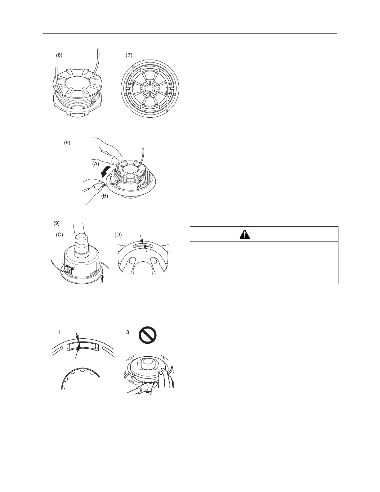
37
Wartung und Pflege
6. Wenn Sie beim Aufwickeln des Faden ans Ende kommen,
klemmen Sie die beiden Fadenenden vorläufig so in die
Schlitze der Fadenspule ein, dass noch ungefähr 10 cm
Faden überstehen.
7. Richten Sie die Schlitze mit dem eingeklemmten Faden so
aus, dass sie sich direkt über den Fadendurchführungen
befinden, und passen Sie die Spule in den Deckel ein.
8. Ziehen Sie den Faden aus dem Deckel. Lösen Sie (A) den
Faden aus den entsprechenden Schlitzen der Fadenspule,
und führen Sie ihn (B) durch die beiden
Fadendurchführungen.
9. Fügen Sie Deckel und Gehäuse zusammen. Ordn en Sie (C)
die Fadenösen des Deckels über den Aussparungen in der
Fadenspule an, und drücken Sie (D) die beiden Stifte des
Gehäuses ganz in die Aussparungen der Fadenspule, bis
sie fest in die Fenster einrasten.
Überprüfen des Nylonfadenkopfs
1. Vergewissern Sie sich, dass jeder der 2 Rückhaltestifte des
Gehäuses vollst ändig in d ie entsprec henden Auss parungen
eingerastet ist.
2. Überprüfen Sie die Montage des Fadenkopfs am Trimmer,
und ziehen Sie ihn fest, falls er lose ist.
3. Überprüfen Sie den Fadenkopf durch Drehen per Hand auf
unrunden Lauf und ungewöhnliche Geräusche. Bei
unrundem Lauf und ungewöhnlichen Geräuschen können
Vibrationen auftreten, die sich auf den Trimmer übertragen
können. Dadurch können sich Teile lösen und eine Gefahr
darstellen.
GEFAHR
Vergewissern Sie sich, dass die Stifte vollständig in die
Fenster der Fadenspule eingerastet sind. Wenn sie nur
leicht hineingesteckt sind und sich der Fadenkopf zu
drehen beginnt, können sich der Deckel oder innere Teile
lösen und davon geschleudert werden, was sehr
gefährlich ist.
Page 84

38
Wartung und Pflege
4. Überprüfen Sie die Abdeckung und den Auslöseknopf auf
Abnutzung. Wenn am unte ren Bereich d es Auslöseknopfs
oder in der Nähe des Nylo nfadenaustritts e in Spalt zu sehen
ist, ersetzen Sie diese Teile umgehend durch neue.
5. Prüfen Sie den Fadenkopf auf Bruch oder Absplitterung.
Ersetzen Sie alle Teile, die gebrochen sind oder
Absplitterungen aufweisen, umgehend durch neue.
Page 85

39
Wartung und Pflege
Fehlerbehebung
Problem Diagnose Ursache Lösung
Der Motor lässt
sich nicht starten.
Im Kraftstofftank ist kein Kraftstoff
Der Stoppschalter steht auf „Stop"
Es wurde zu viel Kraftstoff angesaugt
Elektrischer Defekt
Vergaser defekt oder innerlich verklebt
Interner Defekt des Motors.
Kraftstoffversorgung
Auf „Start" stellen
Motor nach Wartung
starten
ECHO-Händler um Rat
fragen
ECHO-Händler um Rat
fragen
ECHO-Händler um Rat
fragen
Motor lässt sich
schwer starten,
Drehzahl schwankt
Kraftstoff tritt in das
Überlaufr ohr ein
Kraftstoffalterung
Vergaserstörung
Kraftstoff durch neuen
ersetzen
ECHO-Händler um Rat
fragen
In das Überlaufrohr tritt kein
Kraftstoff ein.
Kraftstofffilter ist verstopft
Kraftstoffsystem ist verstopft
Innere Vergaserteile sind verklebt
Reinigen oder ersetzen
ECHO-Händler um Rat
fragen
ECHO-Händler um Rat
fragen
Die Zündkerze ist verschmutzt
oder feucht.
Kraftstoffalterung
Falscher Elektrodenabstand
Kohlenstoffablagerungen
Elektrischer Defekt
Ersetzen
Ersetzen
Ersetzen
ECHO-Händler um Rat
fragen
Motor springt an,
Drehzahl lässt sich
jedoch nicht
erhöhen.
Verschmutzter Luftfilter
Verschmutzter Kraftstofffilter
Verstopfte Kraftstoffleitung
Falsch justierter Vergaser.
Verstopfte Auspuff- oder
Schalldämpferöffnung
Reinigen oder ersetzen
R
einigen oder ersetzen
ECHO-Händler um Rat
fragen
Justieren
Reinigen
Der Motor geht aus Falsch justierter Vergaser.
Elektrischer Defekt
Justieren
ECHO-Händler um Rat
fragen
Der Motor lässt
sich nicht
ausschalten
Stoppschalter defekt NOT-AUS durchführen
und ECHO-Händler um
Rat fragen
Schneidvorrichtung
dreht sich,
während Motor mit
Leerlaufdrehzahl
läuft
Falsch justierter Vergaser.
Beschädigte Kupplungsfeder
Justieren
ECHO-Händler um Rat
fragen
Für Überprüfung und Wartung sind entsprechende Fachkenntnisse erforderlich. Wenn Sie das Produkt nicht selbst
überprüfen, warten oder instand setzen können, wenden Sie sich an Ihren ECHO-Händler. Versuchen Sie nicht, das Gerät
zu zerlegen.
Bei Problemen oder Störungen, die nicht in der obigen Tabelle genannt werden, wenden Sie sich an Ihren ECHO-Händler.
Verwenden Sie nur Original-Ersatzteile und -Verbrauchsprodukte, die für das Gerät zugelassen sind. Die Verwendung von
Teilen anderer Hersteller oder nicht zugelassener Produkte kann zu Fehlfunktionen führen.
Page 86

40
Lagerung
Lagerung
Langfristige Lagerung (30 Tage und länger)
1. Entleeren Sie den Kraftstofftank vollständig.
2. Stellen Sie den Zündsc halter in die Position „Stopp".
3. Sobald das Gerät ausreichend abgekühlt ist, wischen Sie
Schmierfett, Öl, Staub, Schmutz und andere Ablagerungen
außen am Trimmer ab.
4. Führen Sie die regelmäßigen Überprüfungen durch, die in
dieser Bedienungsanleitung beschrieben sind.
5. Vergewissern Sie sich, dass Schrauben und Muttern fest
angezogen sind. Ziehen Sie lose Schrauben und Muttern
fest.
6. Entfernen Sie die Zündkerze, un d füllen Sie die erforderli che
Menge (ca. 10 ml) frisches Zweitaktmotoröl durch die
Zündkerzenöffnung in den Zylinder ein.
7. Bauen Sie die Zündkerze ein (schließen Sie den
Zündkerzensteck er nic ht an. )
8. Bringen Sie die Messerabdeckung am Trimmermesser an,
umhüllen Sie den Motorbereich mit einem Kunststoffsack
oder Ähnlichem, und lagern Sie das Gerät an einem
trockenen, staubfrei en Ort auß erha lb der Reic hw ei te von
Kindern.
WARNUNG
Lagern Sie das Gerät nicht in verschlossenen Räumen, aus denen Kraftstoffverdunstungen nicht
entweichen können, und nicht in der Nähe von Flammen oder Funken.
Brandgefahr.
Wenn Sie das Produkt lange Zeit lagern möchten (30 Tage und länger), gehen Sie folgendermaßen vor:
A. Entfernen Sie den gesamten Kraftstoff aus dem
Kraftstofftank.
B. Entfernen Sie den Kraftstoff aus der Kraftstoffpumpe,
indem Sie sie me hrmals drücken und w ieder los lassen.
C. Starten Sie den Motor, und lassen Sie ihn mi t
Leerlaufdrehzahl laufen, bis er von selbst ausgeht.
1. Zündschalter 2. Gashebel
A. Legen Sie ein sauberes Tuch über die
Zündkerzenöffnung.
B. Ziehen Sie zwei- bis dreimal am Startergriff, um das
Motoröl im Zylinder zu verteilen .
1. Zündkabel 2. Zündkerze
Zur vorschriftsmäßigen Entsorgung des Produkts oder seiner Einzelteile wenden Sie sich an Ihren ECHO-Händler.
Page 87

41
Technische Daten
Technische Daten
Änderungen der technisc hen Daten vorbehalten.
RM-410ES
Außenabmessungen:
Länge × Breite × Höhe mm 2770 × 360 × 560
Maße:
Gerät ohne Schneidvorrichtung, leerer Tank
Gerät mit vorgeschriebener Schneidvorrichtung, leerer
Tank
Gerät mit vorgeschriebener Schneidvorrichtung, voller
Tank
kg
kg
kg
11,5
12,0
12,9
Fassungsvermögen: Kraftstofftank L 1.2
Schneidvorrichtung:
Vorgeschriebener Messerdu rch me sser
Vorgeschriebene Messerst ärke
Anzahl der Schneidzähne
Durchmesser des Schneidmesserzentrierlochs
Messerdrehzahl bei maximal zulässiger Motordrehzahl
mm
mm
mm
U/min
255
3,0
3
25,4
100000
Untersetzungsverhältnis: Untersetzungsverhältnis und
Schmierung
Untersetzung 1,33; hochwer tiges Lithium-
Schmiermittel
Drehrichtung des Werkzeugaufnahmebolzens von
oben gesehen:
Gegen den Uhrzeigersinn
Motor: Typ Luftgekühlter Zweitakt-Einzylindermotor
Hubraum
Maximale Motorleistung nach
Motordrehzahl bei maximaler Motorleistung
Empfohlene maximale Motordrehzahl (mit angebrachter
Standardschneidvorrichtung)
ml (cm
3
)
kW
U/min
U/min
42,7
1,68
8000
10500
Vergaser
Zündung
Zündkerze
Anlasser
Kupplung
Membrantyp
Schwungradmagnet – CDI-System
NGK BPMR7A
Reversierstarter
Automatische Fliehkraftkupplung
Kraftstoff:
Öl
Verhältnis
Bleifreies Normalbenzin. Verwenden Sie bleifreies
Benzin mit mindestens 89 Oktan. Verwenden Sie
keinen Kraftstoff mit Methylalkohol oder mehr als
10 % Ethylalkohol. Motoröl für luftgekühlte
Zweitaktmotoren. ISO-L-EGD-Norm (ISO/CD
13738), JASO FC, FD und ECH O Pre mi um 50 : 1 Öl.
50 : 1 (2%)
Kraftstoffverbrauch bei maxi maler Motorleistung
Spezifizierter Kraftstoffverbrauch bei maximaler
Motorleistung
kg/h
g/(kW•h)
0,89
529
Schalldruckpegel: (ISO 22868) L
pAeq
dB(A) 91,9
Garantierter Schallleistungspegel: (ISO 22868) L
WA
dB(A) 109
Schwingungspegel: (ISO 22867)a
hv,eq
m/s
2
m/s
2
Vorderer Griff 4,8
Hinterer Griff 4,7
Page 88

42
EG-Konformitätserklärung
EG-Konformitätserklärung
Der unterzeichnete Hersteller:
KIORITZ CORPORATION 7-2 SUEHIROCHO 1-CHOME OHME; TOKIO
198-8711
JAPAN
erklärt, dass das nachstehend spezifizierte neue Gerät:
TRAGBARE MOTORSENSE
Marke: ECHO
Typ: RM-410ES
Folgendem entspricht:
* Anforderungen der Richtlinie 98/37/EC (1998) (Verwendung der harmonisierten Norm ISO11806 (EN 31806))
* Anforderungen der Richtlinie 2004/108/EC (Verwendung der harmonisierten Norm EN ISO 14982)
* Anforderungen der Richtlinie 2002/88/EC
* Anforderungen der Richtlinie 2000/14/EC
Konformitätsermittlung nach ANHANG V
RM-410ES
Gemessener
Schallleistungspegel
dB(A) 106
Garantierter
Schallleistungspegel
dB(A) 109
Seriennummer 36001001 und höher
Tokio, 1. November 2008
Autorisierter Repräsentant in Europa:
Unternehmen: Countax Limited
Adresse: Countax House, Haseley Trading Estate,
Great Haseley, Oxfordshire OX44 7PF, U.K.
F. Aiyama General Manager
Herr Harry Handkammar
Page 89

43
EG-Konformitätserklärung
Page 90

44
X750-012 05 0
X750 222-620 0
1Notizen und hintere Um schlagseite
7-2 SUEHIROCHO 1-CHOME, OHME, TOKIO 198-8711, JAPAN
TELEFON: 81-428-32-6118. FAX: 81-428-32-6145.
Gedruckt in Japan 0x0xxxx zzzz ES
2008
Page 91

1Coperchio
ITALIANO
MANUALE PER L'OPERATORE
RM-410ES
AVVERTENZA
LEGGERE E SEGUIRE ATTENTAMENTE LE ISTRUZIONI PER LAVORARE IN CONDIZIONI DI MASSIMA SICUREZZA. LA MANCATA OSSERVANZA DELLE ISTRUZIONI POTREBBE PROVOCARE
LESIONI GRAVI.
Page 92

2
Informazioni importanti
2Informazioni importanti
Si raccomanda di leggere il manuale per l'operatore prima di utilizzare questo prodotto.
Funzione di questo prodotto
I decespugliatori ECHO sono attrezzi leggeri a elevate prestazioni con motore a benzina, realizzati per tenere sotto
controllo la crescita dell'erba, per tagliare i bordi ed eseguire un leggero disboscamento in aree difficili da controllare
con altri mezzi.
Non usare questa macchina per fini diversi da quelli sopra menzionati.
Utenti del prodotto
Prima di utilizzare questo prodotto leggere attentamente e assimilare il contenuto del manuale per l'operatore.
Non utilizzare questo prodotto senza aver prima letto attentamente il manuale per l'operatore, in condizioni debilitate
a causa di raffreddore o stanchezza o in condizioni fisiche e psicologiche non ottimali; inoltre vietare l'uso ai bambini.
Tenere presente che l'operatore o l'utente è re sponsabile di eventua li rischi o i ncidenti pro vocati ad altre persone o alle
proprietà altrui.
Informazioni sul manuale per l'operatore
Questo manuale contiene informazio ni necessarie per l'assembla ggio, il fun zionamento e la manutenz ione del prodo t-
to. Si raccomanda di leggerlo attentamente e di assimilarne il contenuto.
Tenere sempre il manuale in un posto facilmente accessibile.
Se il manuale viene sm arri to o da nne ggi ato e non può essere consultato, acquistarne u no nuovo presso il rivenditore
ECHO.
Le unità di misura ut ilizzate in ques to manuale s ono espresse in conformità al sistema inte rnazionale. L e cifre riportate
tra parentesi sono valori di riferimento e in alcuni casi ci potrebbero essere lievi errori di conversione.
Prestito o cessione del prodotto
In caso di prestito o cessi one del prodotto descri tto in questo manuale, co nsegnare alla person a che lo riceve in prestit o
e che dovrà utilizzarlo anc he il man ual e per l' op erat ore. Anche in caso di cessione, consegnare il prodotto insieme al
manuale per l'operatore.
Richieste
Per ricevere ulteriori informazioni sul prodotto, per l'acquisto di articoli di consumo, per riparazioni e altre eventuali ri-
chieste, contattare il proprio rivenditore ECHO.
Avvisi
Il contenuto di questo manuale può essere modificato senza preavviso per renderlo conforme a eventuali aggiorna-
menti al prodotto. Alcune illustrazioni potrebbero essere divers e dal prodotto per rendere le spiegazioni più chiare.
Questo prodotto richiede l'assemblaggio di alcune parti.
Consultare il proprio rive nditore ECHO per ulteriori chiarimenti.
Page 93

3
Contenuto
Per un uso sicuro del prodotto............................................................................................4
Messaggi di avviso ........................................................................................................4
Altri indicatori.................................................................................................................4
Simboli...........................................................................................................................4
Posizione in cui è applicata una decalcomania .............................................................6
Gestione del carburante ................................................................................................7
Gestione del motore ......................................................................................................8
Gestione del prodotto ....................................................................................................9
Contenuto della confezione.............................................................................................. 15
Descrizione.......................................................................................................................16
Prima di iniziare ................................................................................................................17
Montaggio....................................................................................................................17
Preparazione del carburante .......................................................................................21
Funzionamento del motore ...............................................................................................22
Avviamento del motore................................................................................................22
Arresto del motore .......................................................................................................24
Operazioni di taglio...........................................................................................................25
Funzionamento base del taglio con testina a filo di nylon ...........................................26
Funzionamento base del taglio con disco metallico ....................................................28
Precauzioni a cui attenersi durante il lavoro................................................................29
Manutenzione e cura ........................................................................................................31
Guida alla manutenzione.............................................................................................31
Manutenzione e cura...................................................................................................31
Rimessaggio.....................................................................................................................40
Rimessaggio per un lungo periodo (oltre 30 giorni).....................................................40
Caratteristiche tecniche ................................................ ...... ...... ....... ...... ....... ...... ....... ...... . 41
Dichiarazione di conformità "CE"......................................................................................42
Page 94

4
Per un uso sicuro del prodotto
Per un uso sicuro d el prodotto
Leggere questa sezione prima di utilizzare il prodotto.
Le precauzioni desc ritte in q uest a s ezione contengono importanti informazioni per la s icure zza. Si raccomanda di se-
guirle scrupolosamente.
Leggere anche le precauzioni presenti all'interno del man uale .
Il testo seguito da un contrassegno [a forma di rombo] descrive le potenziali conseguenze che si potrebbero verificare in caso di
mancata osservanza delle precauzioni.
Messaggi di avviso
Situazioni in cui c'è il risc hio di causa re les ioni fis iche all'u tente e ad altre person e sono i ndica te in qu esto m anual e e sul prod otto ,
con le seguenti avve rtenze. Leggerle e osservarle sempre per lavorare in condizioni di massima sicurezza.
Altri indicatori
Oltre alle avvertenze, questo manuale utilizza i seguenti simboli esplicativi:
Simboli
In questo manuale e s ul p rodotto sono ripor tati alc uni sim boli espl icativ i. Ac certars i di aver ben comp reso il sign ifica to di tu tti i simboli.
PERICOLO AVVERTENZA ATTENZIONE
Questo simbolo accompagnato dalla
parola "PERICOLO" richiama l' attenzione su un'azione o una condizione
che potrebbe causare infort uni gravi o
la morte di utenti o d i persone pre senti.
Questo simbolo ac compagnato dalla
parola "AVVERTENZA" richiama
l'attenzione su un'azio ne o una condizione che potrebbe causa re les ion i
gravi o la morte di utenti o di persone
presenti.
"ATTENZIONE" indica una situazione potenzialmente pericolosa che, se
non evitata, potrebbe causare lesioni
minori o moder ate.
Il cerchietto barrato sta
ad indicare che quanto
è illustrato è proibito.
NOTA IMPORTANTE
Il messaggio qui riportato fornisce
consigli per l'uso, la cura e la manutenzione del prodotto.
Il testo incorniciato, caratterizzato
dalla parola "IMPORTANTE", contiene informazioni importanti riguardo
l'uso, il controllo , la manutenz ione e il
rimessaggio del prodotto descritto in
questo manuale.
Forma del simbolo Descrizione / applicaz ione del
simbolo
Forma del simbolo Descrizione / applicazione del
simbolo
Leggere attentamente il manuale per l'operatore
Massima velo cità albero
dell'accessorio di taglio (giri/
min)
Indossare protezioni per occhi, orecchi e testa
Tenere gli astanti a una distanza di 15 m
Indossare protezioni per i piedi e guanti
Miscela di benzina e olio
Arresto di emergenza
Bulbo di spurgo (adescamento)
Page 95

5
Per un uso sicuro del prodotto
Avvertenza! Oggetti scagliati!
Regolazione carburatore Bassi regimi
Attenzione, spinta laterale
Regolazione carbura tore - Alti
regimi
Vietato l'uso senza protezione
Regolazione carburatore Folle
Vietato l'uso di dischi metallici Lubrificare ogni 18 ore
L'uso della testina a filo di
nylon non è consentito
Impugnatura ad anello
Non utilizzare il prodotto in
luoghi dove c'è s c ars a v ent ila zione
Prestare attenzione nell e aree
ad alta temperatura
Attenzione al fuoco
Livello di potenza acustica garantito
Controllo valvola dell'aria Posizione "Avviamento a fre ddo"
(Valvola dell'aria chiusa)
Controllo valvola dell'aria Posizione "In funzione" (Valvola
dell'aria aperta)
Attenzione alle scosse elettriche
Forma del simbolo Descrizione / applicaz ione del
simbolo
Forma del simbolo Descrizione / applicazione del
simbolo
Page 96

6
Per un uso sicuro del prodotto
Posizione in cui è applicata una decalcomania
La decalcomania riportata sotto è stata applica ta sui prodotti descritt i in questo manuale. Prima di utili zzare il prodotto accertarsi
di aver capito il significato della decalcomania.
Se la decalcom ani a d iv enta illeggibile a causa dell'usura, s i s trap pa o s i sta cc a e s i p erd e, a cq uis tarn e u na di ric am bi o p r es so
il rivenditore ECHO e fissarla nel punto illustrato nella figura in basso. Accertarsi che la decalcomania sia sempre leggibile.
1. Decalcomania (Codice ricambio 890617-43130)
Page 97

7
Per un uso sicuro del prodotto
Gestione del carburante
PERICOLO
Rifornire il prodotto di carburante sempre in un'area lontana dal fuoco
Il carburante è altamente infiammabile e può causare incendi se usato senza le dovute precauzioni. Prestare estrema
attenzione durante la preparazione della misc ela, il rim essag gio o il rifornim ento per evita re lesi oni gravi. Os servar e le
seguenti istruzioni.
Non fumare o accendere fiamme durante il rifornimento.
Non effettuare il rifornimento quando il motore è caldo o acceso.
In questi casi il carburante potrebbe incendiarsi.
Contenitore e luogo per il rifornimento
Utilizzare un contenitore di carburante approvato.
I serbatoi/contenitori di c arburante posson o essere sot-
to pressione. Allentare sempre il tappo del carburante
lentamente per compensare la pressione.
NON riempire mai il serbatoio del carburante in ambienti
chiusi. Riempire sempre i serbatoi del carburante
all'aperto su terreno sgombro.
Perdite di carburante possono causare incendi
Osservare le seguenti precauzioni durante il rifornimento:
Non riempire mai il serbatoio del carburante fino all'im-
boccatura. Mantenere il carburante entro il livello prescritto (fino al livello del ser batoio).
Pulire il carburante traboccato o versato.
Serrare bene il tappo del serbatoio carburante dopo il ri-
fornimento.
Il carburante ver sato può c ausare inc endi o sc ottature se in-
fiammato.
1. Serbatoio del carburante
2. Livello
Non avviare il motore nella zon a in cui è stato rifor nito il serbatoio carburante
Non avviare il motore nell'area in cui è stato rifornito il
serbatoio. Prima di avviare il motore, spost arsi almen o
a 3 m dall'area in cui è stato rifornito il serbatoio.
Durante il rifornimento si potreb-
bero verificare perdite di carburante che potrebbero provocare
incendi se infiammate.
Le perdite di carburante causano incendi
Dopo il rifornimento, controllare
sempre che non ci siano perdite o fuoriuscite dal condotto del carburante, dal gommino dell'impianto di alimentazione o intorno al tappo del serbatoio.
In caso di perdite o fuoriuscite di carburante, smettere
immediatamente di usare la macchina e contattare il rivenditore ECHO per la riparazione.
Qualsiasi perdita di carburante può causare incendi.
Page 98
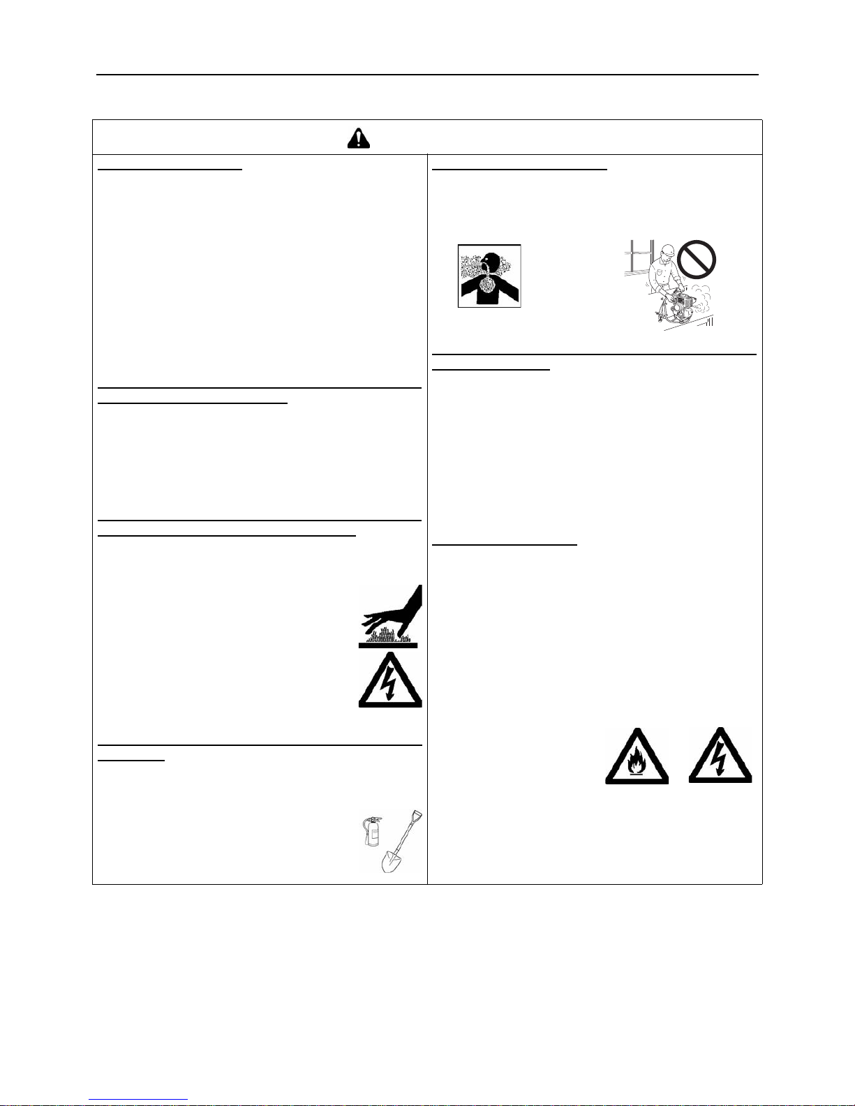
8
Per un uso sicuro del prodotto
Gestione del motore
AVVERTENZA
Avviamento del motore
Prestare particolare attenzione alle seguenti precauzioni
quando si avvia il motore:
Controllare che non ci siano dadi o bulloni allentati.
Controllare che non vi siano perdite di carburante
Collocare il prodotto su un a s upe rf icie pi ana e be n v en-
tilata.
Lasciare sufficiente spazio intorno al prodotto e non
permettere a persone o animali di avvicinarsi
Avviare il motore con la leva del gas in folle
Mantenere il prodotto fermo a terra durante l'avvio del
motore
La mancata osse rvanza di que ste prec auzioni pu ò provoca-
re incidenti, lesioni o perfino la morte.
Una volta avviato il motore, verificare che non ci siano vibrazioni e rumori anomali
Una volta avviato il motore, verificare che non ci siano
vibrazioni o rumori anomali. Non utilizzare il prodotto se
ci sono vibrazioni o rumori anomali. Contattare il rivenditore ECHO per la riparazione.
Incidenti che provoca no la caduta o la rottu ra di p arti po sso-
no causare ferite o lesioni gravi.
Non toccare i componenti ad alta temperatura o ad
alta tensione mentre il prodotto è in moto
Non toccare i seguenti componenti ad alta temperatura o
ad alta tensione mentre il prodotto è in moto o è stato appena spento.
Marmitta, candela, trasmissione a ngolare e
altri componenti ad alta temperatura
Il contatto con componenti ad alta temperatu-
ra potrebbe causare ustioni.
Candela, cavo candela e altri compo-
nenti ad alta tensione
Il contatto con componen ti ad alta tensione
mentre il prodotto è in moto potrebbe causare scosse elettriche.
Dare assoluta priorità alla sicurezza in caso di incendio o fumo
In caso di fuoriuscita di fiamme dal m otore o di fumo da
qualsiasi area diversa dallo sfiato della marmitta, allontanarsi dal prodotto per evitare lesioni gravi.
Utilizzare una pala per lanciare sabbia o al-
tro materiale simile sul fuoco per evitarne
l'espansione o spegnerlo co n un estintore.
Evitare di farsi p rendere dal panico pe r non al-
largare l'incendio o aumentare i danni.
I gas di scarico sono tossici
I gas di scarico provenienti dal m otore contengono gas
tossici. Non utilizzare il prodotto in ambienti chiusi o
scarsamente ventilati.
I gas di scarico possono provocare avvelenamento.
Durante il controllo o la manutenzione del prodotto
spegnere il motore
Osservare le seguenti precauzioni durante il controllo e la
manutenzione del prodotto dopo l'uso:
Spegnere il motore ed eseguire il controllo o la manu-
tenzione del prodotto solo dopo che il motore si è raffreddato.
Interventi a motore caldo potrebbero causare ustioni.
Prima di eseguire il controllo e la manutenzione rimuo-
vere il cappuccio della candela.
Un'avvio imprevisto del prodotto potrebbe causare un inci-
dente.
Controllo della candela
Osservare le seguenti precauzioni duran te il controllo della candela.
Se i terminali degli elettrod i sono usurati o se le pa rti in
ceramica presentano sp accature, sostitui rli con componenti nuovi.
Il test di scintillamento (per verificare se la candela ge-
nera scintille) deve essere eseguito dal RIVENDITORE
ECHO.
Il test di scintillamento non deve essere eseguito in
prossimità del foro della candela.
l test di scintillamento non deve e ssere es egui to vicino
a perdite di carburante o gas infiammabili.
Non toccare le parti me-
talliche della candela
La candela può generare
fiamme o scosse elettriche.
Page 99

9
Per un uso sicuro del prodotto
Gestione del prodotto
Precauzioni generali
AVVERTENZA
Manuale per l'operatore
Per un corretto funzionamento del pro-
dotto, prima di utilizzarlo le ggere attentamente il manuale per l'operatore.
La mancata osservanza di queste precau-
zioni potrebbe causare un incidente o lesioni gravi.
Non utilizzare il prodotto per eseguire lavori diversi
da quelli per cui è stato progettato
Non utilizzare il prodotto per eseguire lavori diversi da
quelli descritti nel manuale dell'operatore.
La mancata osservanza di queste precauzioni potrebbe
causare un incidente o lesioni gravi.
Non modificare il prodotto
Non modificare il prodotto.
La mancata osservanza di queste precauzioni potrebbe
causare un incidente o lesioni gravi. Qualsiasi guasto causato da modifiche apportate al prodotto non sarà coperta
dalla garanzia del produttore.
Non utilizzare il prodotto senza aver effettuato prima
il controllo e la manutenzione
Non utilizzare il prodotto senza aver effettuato prima il
controllo e la manutenzione. Accertarsi sempre che il
controllo e la man utenzione vengano eseguiti a scadenze regolari.
La mancata osservanza di queste precauzioni potrebbe
causare un incidente o lesioni gravi.
Prestito o cessione del prodotto
In caso di prestito del prodotto, consegnare alla perso-
na che lo riceve anche il manuale dell'operatore.
Anche in caso di cessione, consegnare il prodotto insie-
me al manuale per l'operatore.
La mancata osservanza di queste precauzioni potrebbe
causare un incidente o lesioni gravi.
Essere pronti in caso di lesioni
Nell'improbabile evento di incidente o lesioni è consigliabile essere preparati.
Cassetta di pronto soccorso
Asciugamani e fazzoletti (per fermare eventuali emor-
ragie)
Fischietto o telefono cellulare (per chiedere aiuto)
Se non si è in grado di effettuare un primo soccorso o chie-
dere aiuto, le lesioni potrebbero peggiorare.
Page 100

10
Per un uso sicuro del prodotto
Precauzioni per l'uso
PERICOLO
Non utilizzare il prodotto mentre la lama del bordatore sta girando in folle
Non utilizzare il prodotto mentre la lama bordatore sta
girando se il decespugliatore è in moto con la leva del
gas in folle.
La mancata osservanza di queste precauzioni potrebbe
causare un incidente o lesioni gravi.
Non rimuovere la protezione
Non utilizzare il prodotto senza protezione.
Qualsiasi og getto che rimbalza dal la lama del bordatore può
provocare un incidente o lesioni gravi.
L'area nel raggio di 15 m dev e essere considerata
zona pericolosa
L'area nel raggio di 15 m dal prodotto deve essere considerata zona pericolosa. O sservare le seguenti precau zioni
mentre si sta lavorando con il prodotto.
Non permettere a bambini, a ltre persone o animali di en-
trare nella zona pericolosa.
Se altre persone entrano nella zona pericolosa, spegne-
re il motore per fermare la rotazione della lama
Prima di avvicinarsi all'utente, fargli prima un segnale,
per esempio, gettando dei ramosc elli dall'esterno della
zona pericolosa, quindi controllare che il motore sia
spento e la lama ferma.
Se più persone devono lavorare con il prodotto, trovare
un modo per comunicare co n il collega d a una distanz a
di 15 m
Qualsiasi oggetto che rimbalza dalla lama del bordatore e
qualsiasi contatto con la lama può causare cecità o morte.
 Loading...