

Page 1
INSTALLATION INSTRUCTIONS
TM
REPOWER
PART
NUMBER 90094
FOR MODELS: PP-600, 800, PPF-2100, 2110, PPSR-2122, 2433,
PPF-210, 211, PPF-265
CUTTING ATTACHMENT TO SHAFT TUBE INSTALLATION
Tools Required: 10 mm hex socket wrench, screwdriver, 4 mm hex key
wrench. Drill, 7 mm (1/4 in.) drill bit.
W ARNING DANGER
Saw Chain is sharp! Always wear gloves when handling assembly,
otherwise serious personal injury may result.
1 . Follow Guide Bar and Saw Chain Replacement Instructions in
your Operator’s Manual to remove guide bar and saw chain from
existing cutting attachment.
GEAR CASE
NOTE
If standard guide bar with front-access chain tensioner will be
used, remove chain tensioner and install parts on new gear case.
Follow guide bar and saw chain installation, adjustment, and
replacement instructions in your original operator’s manual. If
mounting the side access IntenzTM guide bar, follow instructions
provided here.
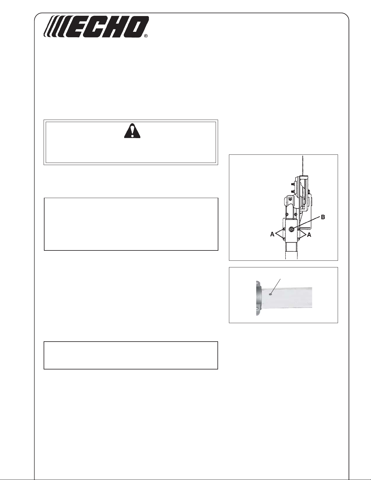
2 . Loosen four (4) screws (A) and locator screw (B), and remove
existing cutting attachment from aluminum shaft tube.
3. OLDER POWER PRUNER MODELS ONLY:
Loosen 4 clamp screws and remove locator screw from Gear
Case. Slide Gear Case on driveshaft tube and align with power
head. Be certain square inner drive shaft engages into square
socket of gear case. If driveshaft and gear case locator holes do
not match, drill a 7 mm (1/4 in. ) hole through one side of shaft
tube, using locator hole in Gear Case as a guide. Remove burrs
from hole, and clear all debris from tube after drilling.
NOTE
Do not allow drill bit to contact inner driveshaft, otherwise
driveshaft may be damaged.
BOTTOM
VIEW
B
X7502307401
X750008571
09/05
Page 2
2
POWER PRUNER
TM
INSTALLATION INSTRUCTIONS
GUIDE
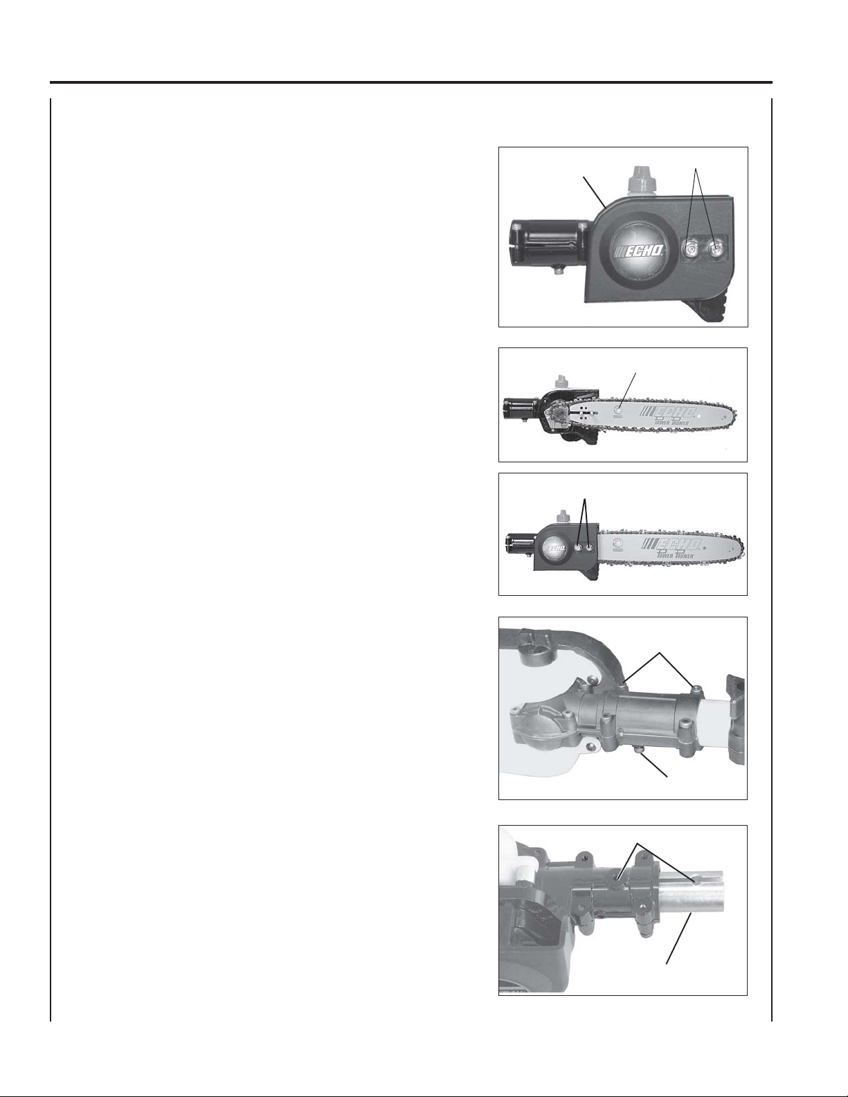
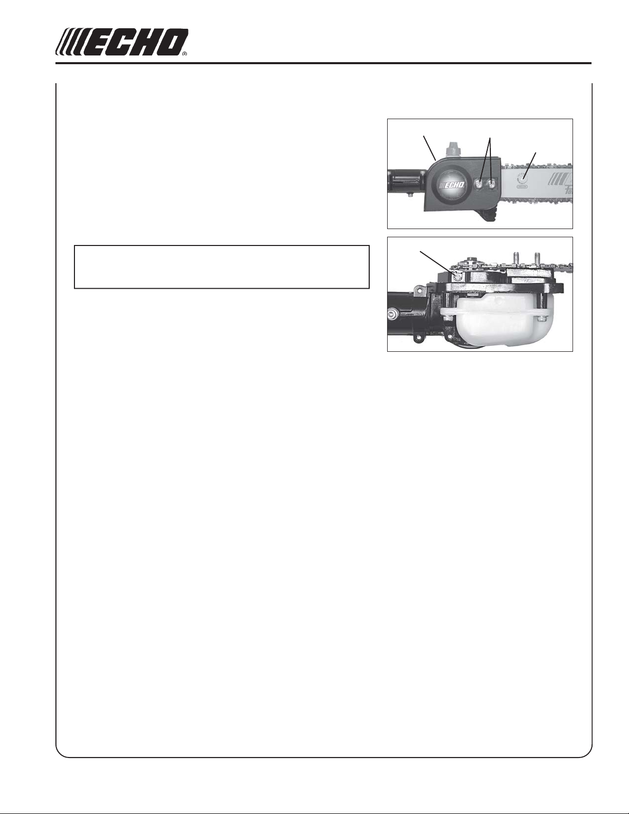
4 . Remove two (2) 6 mm guide bar nuts (C) and remove sprocket
5 . Turn saw chain tension adjuster slot (E) counterclockwise until it
6 . Install chain on guide bar, with cutters on top of bar facing toward
7. Install guide bar and chain on gear case, engaging chain with
8 . Turn tension adjustment slot clockwise to take up slack in saw
BAR AND SAW CHAIN INSTALLATION
cover (D).
stops.
bar tip.
drive sprocket.
chain.
D
E
C
C
9 . Install sprocket guard, and tighten guide bar nuts (C) finger tight.
10. Adjust chain tension. See Saw Chain Tension Adjustment
Instructions on Page 5 of this manual.
11. Loosen the four (4) screws (A) and remove locator screw (B) from
cutting attachment.
12 . (PPSR-2122/2433 Only) Insert collar (G) into cutting attachment
(long end of collar first) until locator holes (B) are aligned.
A
B
B
G
Page 3
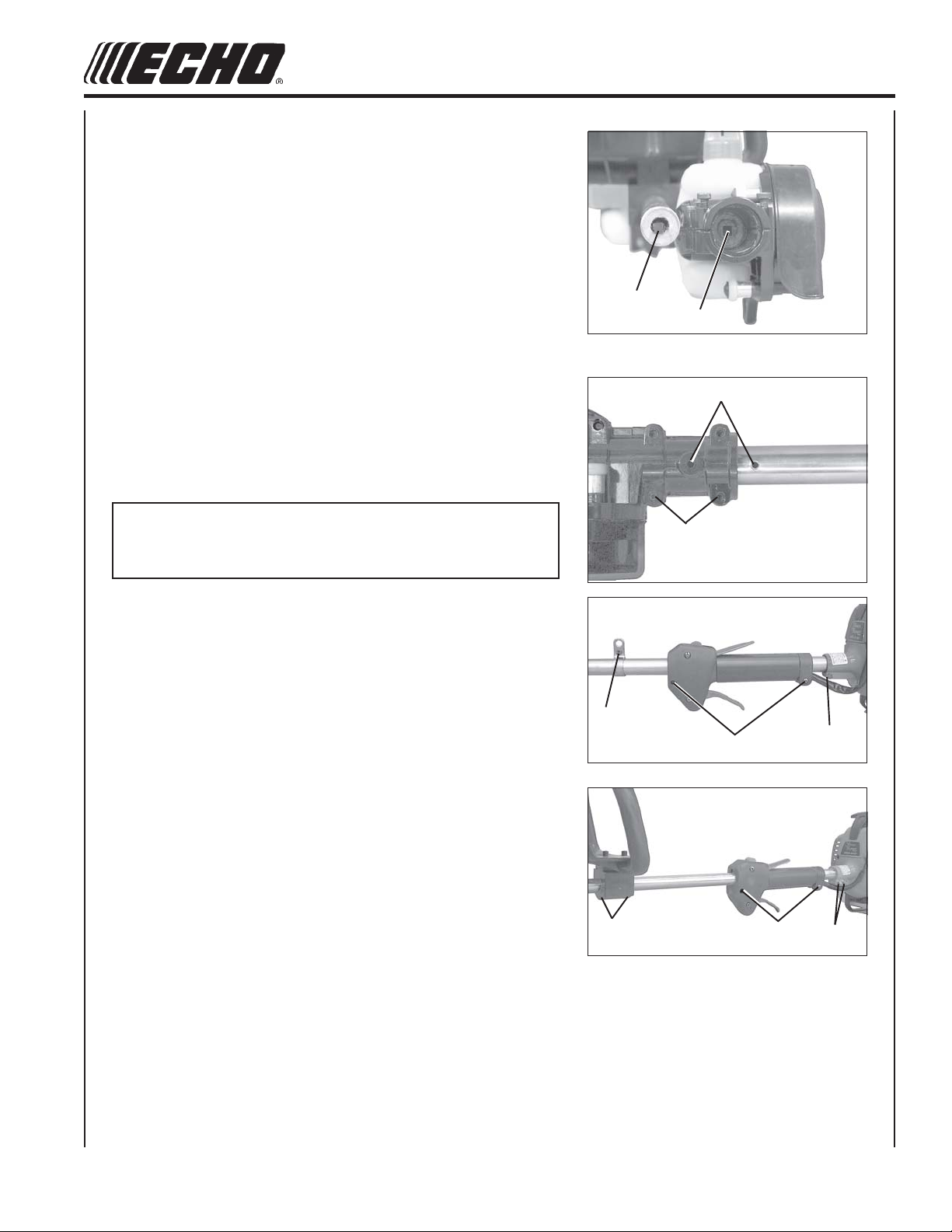
13. Slide cutting attachment onto aluminum shaft tube. Be certain
inner drive shaft (H) engages into square socket (I) of cutting
attachment.
14A.(PPF-210/211/251/2100/2110 Only) Align locator hole (B) in cutting
attachment with locator hole in aluminum shaft tube.
14 B . (PPSR-2122/2433 Only) Align locator hole (B) in cutting attach-
ment and collar with locator hole in aluminum shaft tube.
15. Install and tighten locator screw (B). Tighten four (4) cutting
attachment screws (A).
NOTE
Cutting Attachment Assembly is complete for models PPF-210, 211,
265. All other models follow steps 16 - 19.
3
H
I
B
A
16A.(PPF-2100/2110 Only) Loosen harness clamp screw (J), two (2)
throttle grip clamping screws (K) and engine fan housing clamp
bolt (L).
16 B . (PPSR-2122/2433 Only) Loosen four (4) front handle screws (M),
two (2) throttle grip clamping screws (N) and two (2) engine fan
housing clamp bolts (O).
17A. (PPF-2100/2110 Only) Position cutting attachment upright and
rotate harness clamp, throttle grip, and engine upright on drive
shaft and in-line with cutting attachment.
17B. (PPSR-2122/2433 Only) Position cutting attachment upright and
rotate front handle, throttle grip and engine upright on drive shaft
and in-line with cutting attachment.
18. (All Models) Tighten engine and throttle grip fasteners securely.
19A. (PPF-2100/2110 Only) Install harness and position harness clamp
for comfortable operation. Tighten harness clamp screw securely.
J
L
O
M
K
N
19B. (PPSR-2122/2433 Only) Position front handle for comfortable
operation. Tighten four (4) screws securely.
Page 4
4
POWER PRUNER
TM
INSTALLATION INSTRUCTIONS
GUIDE
BAR AND SAW CHAIN REPLACEMENT
Guide Bar Replacement / Installation
1 . Remove two (2) 6 mm guide bar nuts (C), and turn saw chain
tension adjustment slot (E) counterclockwise to release tension.
2 . Remove sprocket cover (D).
3 . Remove guide bar and saw chain from gear case and sprocket.
4 . Remove chain from guide bar and check guide bar for damage and
excessive or uneven wear. Replace guide bar if necessary.
5 . Turn saw chain tension adjuster slot (E) counterclockwise until it
stops.
6. Install chain on guide bar with cutters on top of bar facing toward
bar tip.
7. Install guide bar and chain on gear case, engaging chain with
drive sprocket (F).
8 . Turn tension adjustment slot clockwise to take up slack in saw
chain.
D
F
C
E
E
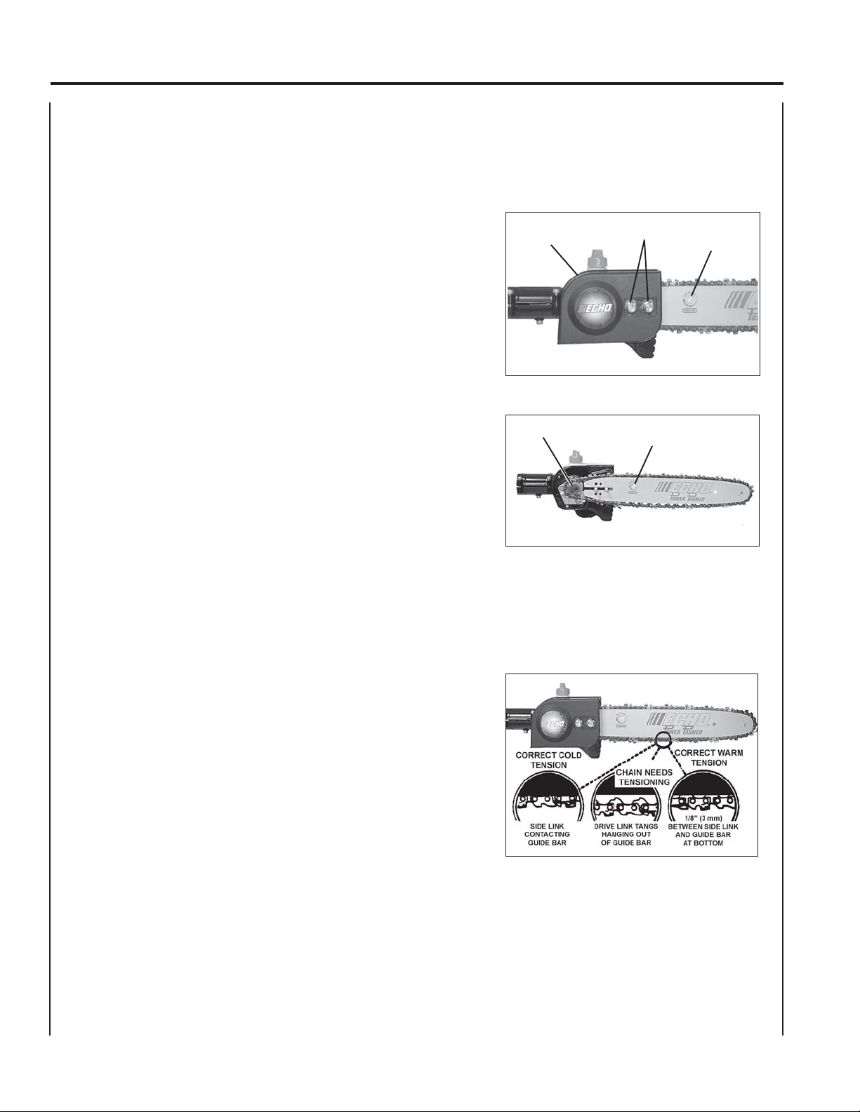
9. Install sprocket guard (D), and tighten guide bar nuts finger tight.
10. Adjust chain tension.
To Adjust Saw Chain Tension.
1. Loosen two guide bar nuts (C), if necessary.
2 . Turn saw chain adjuster slot (E) clockwise to tighten saw chain on
guide bar. Turning slot counter clockwise will loosen saw chain on
guide bar.
3 . Tighten guide bar nuts (C) firmly. Pull the saw chain around the
guide bar by hand. Saw chain should move freely on guide bar. If
saw chain is difficult to rotate or binds on guide bar, it is too tight.
4. Keep the saw chain lubricated and properly adjusted and the
guide bar nuts tightened firmly at all times.
Page 5
ADJUSTING AUTOMATIC OILER
5
1 . Remove two (2) 6 mm guide bar retaining nuts (C) and sprocket
cover (D).
2 . From bottom of gear case, turn adjustment screw (P) clockwise to
decrease oil volume - counter clockwise to increase oil volume.
3 . Install sprocket guard (D) and secure with two (2) guide bar
retaining nuts (C).
NOTE
Very little visible oil on the saw chain will provide sufficient
lubrication.
D
P
C
E
Page 6

INSTRUCCIONES DE INSTALACIÓN
CAJA
PARA LOS MODELOS: PP-600, 800, PPF-2100, 2110, PPSR-2122, 2433
PPF-210, 211, PPF-265
INSTALACIÓN DEL ACCESORIO DE CORTE EN EL TUBO DEL EJE
Herramientas necesarias: Llave de boca hexagonal de 10 mm, destornillador,
llave Allen de 4 mm, taladro, taladro de7 mm
(1/4 pulg)
ADVERTENCIA PELIGRO
¡La cadena de la sierra está afilada! Tenga mucho cuidado al mezclar,
guardar o manipular combustible, ya que se pueden producir lesiones
personales graves.
1 . Siga la página las instrucciones de reemplazo de la barra guía y cadena
de la sierra en el manual del operador para quitar la barra guía y la
cadena de la sierra del accesorio de corte existente.
NOTA
Si se va a usar una barra guía estándar con tensor de cadena de acceso
delantero, quite el tensor de la cadena e instale las piezas en la nueva
caja de engranajes. Siga las instrucciones de instalación, ajuste y
reemplazo de la barra guía y de la cadena de la sierra indicadas en el
manual original del operador. En caso de montar la barra guía Intenz™
de acceso lateral, siga las instrucciones aquí indicadas.
2 . Afloje los cuatro (4) tornillos (A) y el tornillo posicionador (B) y quite el
accesorio de corte existente del tubo del eje de aluminio.
3. MODELOS DE PODADERAS ANTERIORES SOLAMENTE: Afloje 4
tornillos de fijación y quite el tornillo ubicador de la caja de engranajes
Deslice la caja de engranajes por el tubo del eje de impulsión y alinéela
con la cabeza de impulsión. Asegúrese de que el eje de impulsión
interior de sección cuadrada se conecte en el adaptador cuadrado de la
caja de engranajes. Si los orificios del eje de impulsión y del ubicador
de la caja de engranajes no corresponden, perfore un orificio de ¼” (7
mm) por un lado del tubo del eje, usando el orificio ubicador de la caja
de engranajes como guía. Quite las rebabas del orificio, y retire todos
los residuos del tubo después de taladrar.
DE ENGRANAJES REPOWER
NÚMERO DE PIEZA 90094
VISTA
DESDE
ABAJO
TM
B
NOTA
No deje que la broca del taladro haga contacto con el eje de impulsión
interno, de lo contrario el eje de impulsión se puede dañar.
X7502307401
X750008571
09/05
Page 7

INSTALACIÓN DE LA BARRA GUÍA Y CADENA DE LA SIERRA
7
4 . Afloje las dos (2) tuerca de 6 mm de la barra guía (C) y quite la tapa
de la rueda dentada (D).
5 . Gire la ranura (E) del tensor de la cadena de la sierra hacia la
izquierda hasta que se pare.
6 . Instale la cadena en la barra de guía, con los cortadores encima de
la barra apuntando hacia la punta de la barra.
7 . Instale la barra guía y la cadena en la caja de engranajes,
enganchando la cadena con la rueda de impulsión.
8 . Gire la ranura de ajuste de tensión hacia la derecha para tensar la
cadena de la sierra.
9 . Instale el protector de la rueda de impulsión, y apriete las tuercas
de la barra de guía (C) con la mano.
D
E
C
C
10. Ajuste la tensión de la cadena. Vea las Instrucciones de ajuste de
tensión de la cadena de la sierra en la página 4 de este manual.
11. Afloje los cuatro (4) pernos (A) y quite el perno posicionador (B)
del accesorio de corte.
12 . (PPSR-2122/2433 solamente) Inserte el collar (G) en el accesorio de
corte (extremo largo del collar primero) hasta que los agujeros
posicionadores (B) estén alineados.
A
B
B
G
Page 8

8
13. Deslice el accesorio de corte por el tubo del eje de aluminio.
Asegúrese de que el eje de mando interior (H) se enganche en el
adaptador cuadrado (I) del accesorio de corte.
14A. (PPF-210/211/251/2100/2110 solamente) Alinee el agujero
posicionador (F) del accesorio de corte con el agujero
posicionador del tubo del eje de aluminio.
14B. (PPSR-2122/2433 solamente) Alinee el agujero posicionador (F) del
accesorio de corte y el collar con el agujero posicionador del tubo
del eje de aluminio.
POWER PRUNER
TM
INSTALLATION INSTRUCTIONS
H
I
B
15. Instale y apriete el perno posicionador (F). Apriete los cuatro (4)
pernos del accesorio de corte (E).
NOTA
El accesorio del corte es completo para los modelos PPF-210, 211,
265. El resto de los modelos siguen los pasos 16 - 19.
16A. (PPF-2100/2110 solamente) Afloje el tornillo de la abrazadera del
arnés (J), dos (2) tornillos de sujeción de la empuñadura del
acelerador (K) y el perno de la abrazadera de la caja del ventilador
del motor (L).
16B. (PPSR-2122/2433 solamente) Afloje los cuatro (4) tornillos de la
empuñadura delantera (M), dos (2) tornillos de sujeción de la
empuñadura del acelerador (N) y dos (2) pernos de la abrazadera
de la caja del ventilador del motor (O).
17A. (PPF-2100/2110 solamente) Coloque el accesorio de corte en
posición vertical y gire la abrazadera del arnés, empuñadura del
acelerador y motor hasta ponerlos en posición vertical en el eje de
impulsión y alineados con el accesorio de corte.
17B. (PPSR-2122/2433 solamente) Coloque el accesorio de corte en
posición vertical y gire la empuñadura delantera, empuñadura del
acelerador y motor en posición vertical en el eje de impulsión y
alineados con el accesorio de corte.
18. (Todos los modelos) Apriete bien los sujetadores del motor y de la
empuñadura del acelerador.
A
J
L
O
M
K
N
19A. (PPF-2100/2110 solamente) Instale el arnés y coloque la abrazadera
del arnés para una operación cómoda. Apriete bien el tornillo de la
abrazadera del arnés.
19B. (PPSR-2122/2433 solamente) Coloque la empuñadura delantera
para una operación cómoda. Apriete bien los cuatro (4) tornillos.
Page 9

REEMPLAZO DE LA BARRA DE GUÍA Y CADENA DE LA SIERRA
Reemplazo/Instalación de la barra guía
1 . Quite las dos (2) tuercas de 6 mm de la barra guía (C), y gire la
ranura de ajuste de tensión de la cadena de la sierra hacia la
izquierda para destensar.
2 . Quite la tapa de la rueda de impulsión (D).
3 . Quite la barra guía y la cadena de la sierra de la caja de engranajes
y de la rueda de impulsión.
4 . Quite la cadena de la barra guía y compruebe la barra guía para ver
si está dañada y desgastada excesivamente o de forma desigual.
Reemplace la barra guía si es necesario, e instale una cadena nueva
o afilada.
5 . Gire la ranura (E) del tensor de la cadena de la sierra hacia la
izquierda hasta que se pare.
D
9
C
E
6 . Instale la cadena en la barra guía, con los cortadores encima de la
barra apuntando hacia la punta de la barra (F).
7 . Instale la barra guía y la cadena en la caja de engranajes,
enganchando la cadena con la rueda de impulsión.
8 . Gire la ranura de ajuste de tensión hacia la derecha para tensar la
cadena de la sierra.
9 . Instale el protector de la rueda de impulsión (D), y apriete las
tuercas de la barra guía con la mano.
10. Ajuste la tensión de la cadena.
Ajuste de la tensión de la cadena de la sierra.
1 . Afloje dos de la tuerca de la barra de guía (C), se es necesario.
2 . Gire hacia la derecha el tornillo tensor de la cadena de la sierra (E)
(ubicado junto a la barra guía) para apretar la cadena de la sierra en
la barra guía. El giro del tornillo hacia la izquierda aflojará la cadena
de la sierra en la barra guía.
3 . Apriete bien las tuercas de la barra guía (C). Tire de la cadena de la
sierra con la mano alrededor de la barra de guía. La cadena de la
sierra debe moverse libremente en la barra guía. Si es difícil hacer
girar la barra guía o se atasca en la barra guía, está demasiado
apretada.
F
Corregir la
tensión en frio
Coloque el lado
que contacta la
barra
E
La cadena
necesita
tensionamiento
Lleve la unión del
extremo aplastado
de la espiga de una
broca colgando hacia
afuera de la barra
Corregir la tensión
cuando esta
calentando
Tiene que haber una
distancia de 1/8"
(3mm) en medio de
la unión de la barra
y la parte inferior
4. Mantenga la cadena de la sierra lubricada y bien ajustada y las
tuercas de la barra guía bien apretadas en todo momento.
Page 10

10
POWER PRUNER
TM
INSTALLATION INSTRUCTIONS
AJUSTE
1 . Quite las dos (2) tuercas de retención de la barra guía (C) de 6 mm
2 . En la parte inferior de la caja de engranajes, gire el tornillo de ajuste
3 . Instale la tapa de la barra guía (D) y sujétela con dos (2) tuercas de
NOTA
La presencia de muy poco aceite visible en la cadena de la sierra
proporcionará una lubricación suficiente.
DEL ENGRASADOR AUTOMÁTICO
y la tapa de la rueda dentada (D).
(P) hacia la derecha para disminuir el volumen de aceite y hacia la
izquierda para aumentarlo.
retención de la barra guía (C).
D
P
C
E
Page 11

INSTRUCTIONS D’INSTALLATION
CARTER D’ENGRENAGES REPOWER™
RÉF. 90094
POUR MODÈLES : PP-600, 800, PPF-2100, 2110, PPSR-2122, 2433
PPF-210, 211, PPF-265
INSTALLATION DE L’ACCESSOIRE DE COUPE SUR LE TUBE D’ARBRE
Outils nécessaires : Clé hexagonale de 10 mm, tournevis, clé
hexagonale de 4 mm, Foret de 6,35 mm (1/4 po) de
diamètre
AVERTISSEMENT DANGER
La chaîne est tranchante ! Toujours porter de gants lors de la
manipulation de l’accessoire de coupe pour éviter des risques de
blessures graves.
1 . Suivre les instructions de remplacement du guide-chaîne et de la
chaîne du manuel d’utilisation pour retirer le guide et la chaîne de
l’accessoire de coupe d’origine.
REMARQUE
Si le guide standard à tendeur de chaîne à l’avant est utilisé, retirer
le tendeur de chaîne et installer les pièces sur le nouveau carter
d’engrenages. Suivre les instructions d’installation, de réglage et
de remplacement de la chaîne du manuel d’utilisation original. Pour
le montage du guide Intenz
ci-après.
2 . Desserrer les quatre (4) vis (A) et la vis de guidage (B) puis retirer
l’accessoire de coupe monté sur le tube d’arbre en aluminium.
3. MODÈLES D’ÉLAGUEUSE POWER PRUNER ANCIENS
SEULEMENT : Desserrer les quatre vis de serrage et retirer la vis
de guidage du carter d’engrenages. Glisser le carter d’engrenages
sur l’arbre moteur et l’aligner sur le bloc moteur. Veiller à ce que
l’arbre moteur interne s’engage bien dans le carré d’entraînement
du carter d’engrenages. Si les trous de guidage de l’arbre moteur
et du carter d’engrenages ne correspondent pas, percer un trou de
6,35 mm (1/4 po) dans l’un dés côtés du tube de l’arbre, en utilisant
le trou du carter d’engrenages comme guide. Une fois le trou
percé, l’ébavurer et éliminer tous les débris du tube.
REMARQUE
Ne pas laisser le foret entrer en contact avec l’arbre moteur interne,
car celui-ci pourrait être endommagé.
TM
à accès latéral, suivre les instructions
VEU
DU
DESSOUS
B
X7502307401
X750008571
09/05
Page 12

12
POWER PRUNER
TM
INSTALLATION INSTRUCTIONS
INSTALLATION
4 . Desserrer les deux (2) écrous de 6 mm de la barre-guide (C) et
retirer le couvercle de pignon (D).
5 . Gire la ranura (E) del tensor de la cadena de la sierra hacia la
izquierda hasta que se pare.
6 . Instale la cadena en la barra de guía, con los cortadores encima de
la barra apuntando hacia la punta de la barra.
7 . Instale la barra guía y la cadena en la caja de engranajes,
enganchando la cadena con la rueda de impulsión.
8 . Gire la ranura de ajuste de tensión hacia la derecha para tensar la
cadena de la sierra.
9 . Instale el protector de la rueda de impulsión, y apriete las tuercas
de la barra de guía (C) con la mano.
DU GUIDE-CHAÎNE ET DE LA CHAÎNE
D
E
C
C
10. Ajuste la tensión de la cadena. Vea las Instrucciones de ajuste de
tensión de la cadena de la sierra en la página 5 de este manual.
11. Desserrer les quatre (4) boulons (A) et retirer le boulon (B) de
l’accessoire de coupe.
12 . (PPSR-2122/2433 seulement) Insérer le collier (G) sans l’accessoire
de coupe (extrémité longue en premier) et aligner les trous de
guidage (B).
A
B
B
G
Page 13

13. Glisser l’accessoire de coupe sur le tube d’arbre en aluminium.
Veiller à ce que l’arbre moteur (H) s’engage bien dans le carré
d’entraînement (I) de l’accessoire de coupe.
13
14A. (PPF-210/211/251/2100/2110 seulement) Aligner le trou de guidage
(F) de l’accessoire de coupe sur le trou de guidage du tube d’arbre
en aluminium.
14B. (PPSR-2122/2433 seulement) Aligner les trous de guidage (F) de
l’accessoire de coupe et du collier sur le trou de guidage du tube
d’arbre en aluminium.
15. Installer et serrer le boulon de blocage (F). Serrer les quatre (4)
boulons (E) de l’accessoire de coupe.
REMARQUE
L’attachement de découpage est complet pour les modèles
PPF-210, 211, 265. Tous autres modèles suivent les étapes 16 - 19.
16A. (PPF-2100/2110 seulement) Desserrer la vis (J) du collier de
harnais, les deux (2) vis (K) de fixation de la manette des gaz et le
boulon (L) du carter de ventilateur du moteur.
16B. (PPSR-2122/2433 seulement) Desserrer les quatre (4) vis (M) de
poignée avant les deux (2) vis (N) de la manette des gaz et les deux
(2) boulons (O) du carter de ventilateur du moteur.
17A. (PPF-2100/2110 seulement) Mettre l’accessoire de coupe à la
verticale et tourner le collier de harnais, la poignée de manette des
gaz et le moteur à la verticale sur l’arbre en ligne avec l’accessoire
de coupe.
H
I
B
A
J
K
L
17B. (PPSR-2122/2433 seulement) Mettre l’accessoire de coupe à la
verticale et tourner la poignée avant, la poignée de manette des
gaz et le moteur à la verticale sur l’arbre en ligne avec l’accessoire
de coupe.
18 . (Tous les modèles) Serrer fermement la boulonnerie du moteur et
de la manette des gaz.
19A. (PPF-2100/2110 seulement) Installer le harnais et régler son collier
sur une position d’utilisation confortable. Serrer fermement la vis
du collier de harnais.
19B. (PPSR-2122/2433 seulement) Placer la poignée avant sur une
position confortable. Serrer fermement les quatre (4) vis.
M
N
O
Page 14

14
REMPLACEMENT DU GUIDE-CHAÎNE ET DE LA CHAÎNE
Remplacement/installation du guide-chaîne
1 . Quite las dos (2) tuercas de 6 mm de la barra guía (C), y gire la
ranura de ajuste de tensión de la cadena de la sierra hacia la
izquierda para destensar.
2 . Quite la tapa de la rueda de impulsión (D).
3 . Quite la barra guía y la cadena de la sierra de la caja de engranajes
y de la rueda de impulsión.
4 . Quite la cadena de la barra guía y compruebe la barra guía para ver
si está dañada y desgastada excesivamente o de forma desigual.
Reemplace la barra guía si es necesario, e instale una cadena
nueva o afilada.
POWER PRUNER
TM
INSTALLATION INSTRUCTIONS
D
C
E
5 . Gire la ranura (E) del tensor de la cadena de la sierra hacia la
izquierda hasta que se pare.
6 . Instale la cadena en la barra guía, con los cortadores encima de la
barra apuntando hacia la punta de la barra.
7 . Instale la barra guía y la cadena en la caja de engranajes,
enganchando la cadena con la rueda de impulsión (F).
8 . Gire la ranura de ajuste de tensión hacia la derecha para tensar la
cadena de la sierra.
9 . Instale el protector de la rueda de impulsión (D), y apriete las
tuercas de la barra guía con la mano.
10. Ajuste la tensión de la cadena.
Réglage de la tension de la chaîne.
1. Desserrer les deux (2) ecrouse (C), au besoin.
2. Tourner la vis (E) du tendeur de chaîne (se trouvant près du
guide-chaîne) dans le sens horaire pour tendre la chaîne sur le
guide. Tourner la vis dans le sens antihoraire pour détendre la
chaîne.
3 . Serrer fermement les écrous (C) de la barre-guide. Engager la
chaîne sur le guide à la main. La chaîne doit tourner librement sur
le guide. Si la chaîne est difficile à tourner ou se coince sur le
guide, elle est trop tendue.
4 . Veiller à ce que la chaîne soit correctement lubrifiée et ajustée et à
ce que les écrous du guide soient bien serrés en tout temps.
F
TENSION CORRECTE
À FROID
Côté du maillon en
contact avec le guide
E
LA CHAÎNE A BESOIN
D’ÊTRE TENDUE
Les crampons d’entraînement
sont écartés du guide
TENSION CORRECTE
À CHAUD
1/8 po (3 mm) entre le côté
du maillon et le bas du guide
Page 15

RÉGLAGE DU GRAISSEUR AUTOMATIQUE
15
1 . Desserrer les deux (2) écrous de 6 mm de retenue de la barre-guide
(C) et retirer le couvercle de pignon (D).
2. Par le dessous du carter d’engrenages, tourner la vis de réglage (P)
dans le sens horaire pour réduire le débit d’huile et dans le sens
antihoraire pour l’augmenter.
3 . Installer le carter de la barre-guide et l’assujettir avec les deux (2)
écrous de retenue (C).
REMARQUE
Une mince couche d’huile visible sur la chaîne assurera une
lubrification suffisante.
D
P
C
E
Page 16

ECHO CONSUMER PRODUCT SUPPORT: If you require assistance or have questions concerning the application,
operation or maintenance of this product you may call the ECHO Consumer Product Support Department at 1-800-6731558 from 8:30 am to 4:30 pm (Central Standard Time) Monday through Friday. Before calling, please know the model and
serial number of your unit to help your Consumer Product Support Representative.
REPLACEMENT MANUALS: Operator's, Parts, and Safety Manuals may be obtained from ECHO, or may be downloaded free from ECHO's website. Make sure you know the model number and serial number of your unit so you can
obtain the correct manual.
ASISTENCIA AL CLIENTE DE ECHO: Si usted requiere asistencia o tiene preguntas concernientes a la aplicación,
operación, o mantenimiento de este producto llame al departamento de asistencia al cliente de ECHO al 1-800-673-1558 de
8:30 am. a 4:30 pm. (Hora del Centro) de Lunes a Viernes Antes de llamar por favor saber el modelo y numero de serie de
su unidad para ayudar a su representante de asistencia al cliente.
MANUALES DE REPUESTO: Se puede obtener los manuales del operador, piezas y seguridad de ECHO, o se puede
descargar gratis del sitio web de ECHO. Asegúrese de que sepa el número de modelo y el número de serie de su unidad
para que pueda obtener el manual correcto.
SERVICE APRÈS-VENTE ECHO: Pour toute assistance ou question concernant l’application, l’utilisation ou l’entretien
de ce produit, appeler le service après-vente ECHO au 1-800-673-1558, de 08:30 à 16:30 heures (heure normale du centre),
du lundi au vendredi. Avant d’appeler, veiller à disposer des numéros de modèle et de série de l’unité afin d’aider votre
représentant du service après-vente.
MANUELS DE REMPLACEMENT : Des manuels d’utilisation, catalogues de pièces et manuels de sécurité peuvent être
achetés chez les concessionnaires ECHO ou commandés directement chez ECHO. Veiller à toujours fournir les numéros
de modèle et de série de la machine pour 6etre sûr d’obtenir le manuel approprié.
ECHO, INCORPORATED
400 OAKWOOD ROAD
LAKE ZURICH, IL 60047-1564
PHONE: 1-800-673-1558
www.echo-usa.com
 Loading...