

Page 1

POWER PRUNER
TM
Power Pruner
TM
Operator's Manual
MODEL: PPT-260
OPERATOR'S MANUAL
1
W ARNING
Read rules for safe operation and instructions carefully. ECHO provides an Operator's
Manual and a Safety Manual. Both must be read and understood for proper and safe
operation.
X7702090801
X770001021
02/07
Page 2

2
INTRODUCTION
Welcome to the ECHO family. This ECHO product was designed and manufactured to provide long life and on-the-job
dependability. Read and understand this manual and the SAFETY MANUAL you found in the same package. You will
find both easy to use and full of helpful operating tips and SAFETY messages.
THE OPERATOR'S MANUAL
Read and understand this manual before operation. Keep it in
a safe place for future refenence. It contains specifications
and information for operation, starting, stopping, maintenance, storage, and assembly specific to this product.
THE SAFETY MANUAL
Read and understand this manual before operation. Keep it in
a safe place for future refenence. It explains possible hazards
involved with the use of Power PrunerTM and what measures
you should take to make their use safer.
TABLE OF CONTENTS
Introduction ...............................................................2
- The Operator's Manual........................................2
- The Safety Manual .............................................2
Safety .........................................................................3
- Manual Safety Symbols and Important
Information .........................................................3
- International Symbols......................................... 3
- Personal Condition and Safety Equipment .........4
- Kickback .............................................................6
- Equipment ...........................................................7
Emission Control........................................................ 7
Description ................................................................ 8
Contents .................................................................. 10
Assembly ................................................................. 10
- Drive Shaft/Power Head ................................... 1 0
- Cutting Attachment to Drive Shaft Installation 11
- Throttle Linkage and Ignition Leads................. 12
- Saw Chain Tension Adjustment ....................... 12
Operation ................................................................. 13
- Fuel ................................................................... 13
- Lubricating the Guide Bar and Saw Chain ........ 1 5
- Adjusting Automatic Oiler................................ 15
- Starting Cold Engine ......................................... 16
- Starting Warm Engine....................................... 1 7
- Stopping Engine ............................................... 17
- Pruning Techniques ......................................... 18
Copyright© 2007 By Echo, Incorporated
All Rights Reserved.
Maintenance ............................................................ 19
- Skill Levels ........................................................ 19
- Maintenance Intervals ......................................19
- Air Filter ............................................................ 20
- Fuel Filter .......................................................... 20
- Spark Plug......................................................... 21
- Cooling System Cleaning.................................. 2 1
- Exhaust System................................................. 2 2
- Carburetor Adjustment ..................................... 23
- Guide Bar and Saw Chain Replacement ............ 2 5
- Filing Saw Chain ............................................... 27
Troubleshooting ...................................................... 28
Storage..................................................................... 29
Specifications........................................................... 30
Servicing Information............................................... 32
- Parts.................................................................. 32
- Service ..............................................................32
- ECHO Consumer Product Support.................... 32
- Warranty Card .................................................. 3 2
- Additional or Replacement Manuals ................ 32
Specifications, descriptions and illustrative material in
this literature are as accurate as known at the time of
publication, but are subject to change without notice.
Illustrations may include optional equipment and
accessories, and may not include all standard
equipment.
Page 3
POWER PRUNER
TM
OPERATOR'S MANUAL
SAFETY
MANUAL SAFETY SYMBOLS AND IMPORTANT INFORMATION
Throughout this manual and on the product itself, you will find safety alerts and helpful, informational messages
preceded by symbols or key words. The following is an explanation of those symbols and key words and what they
mean to you.
DANGER
The safety alert symbol accompanied by the word
“DANGER” calls attention to an act or condition
which WILL lead to serious personal injury or death
if not avoided.
W ARNING
The safety alert symbol accompanied by the word
“WARNING” calls attention to an act or condition
which CAN lead to serious personal injury or death
if not avoided.
CAUTION
The safety alert symbol accompanied by the word
“CAUTION” calls attention to an act or condition
which may lead to minor or moderate personal injury
if not avoided.
NOTE
This enclosed message provides tips for use, care
and maintenance of the unit.
IMPORTANT
The enclosed message provides information
necessary for the protection of the unit.
CIRCLE AND SLASH SYMBOL
This symbol means the specific action
shown is prohibited. Ignoring these
prohibitions can result in serious or fatal
injury.
3
INTERNA TIONAL SYMBOLS
Symbol form/shape
Symbol
description/application
Read and understand
Operator's Manual.
Wear eyes, ears and
head protection
Hot
Surface
Safety/Alert
Avoid all power
lines. This unit is not
insulated against
electrical current.
Keep bystanders at
least 15 meters
(50 feet) away.
Symbol form/shape
Symbol
description/application
Fuel and oil mixture
Finger Severing
Wear hand
protection. Use
two handed.
DO NOT smoke
near fuel.
Do not operate closer than 15 M (50 ft.)
from electrical
hazards.
Plan retreat path
from falling
objects.
Symbol form/shape
Symbol
description/application
DO NOT allow
flames or sparks
near fuel.
Emergency stop
Chain lubrication
Carburetor adjustment
- Low speed mixture
Carburetor adjustment
- Idle speed
Choke Control
"Cold Start"
Position
(Choke Closed)
Symbol form/shape
Symbol
description/application
Wear slip resistant
foot wear.
Ignition
ON/OFF
Primer bulb
Carburetor adjustment
- High speed mixture
Choke Control
"Run"
Position
(Choke Open)
Page 4
4
PERSONAL CONDITION AND SAFETY EQUIPMENT
WARNING
Power PrunerTM users risk injury to themselves and others if the Power PrunerTM is used improperly and or safety
precautions are not followed. Proper clothing and safety gear must be worn when operating a Power PrunerTM.
Physical Condition
Your judgment and physical dexterity may not be good:
• if you are tired or sick,
• if you are taking medication,
• if you have taken alcohol or drugs.
Operate unit only if you are physically and mentally well.
Eye Protection
Wear eye protection that meets ANSI Z87.1 or CE
requirements whenever you operate the unit
Face and Head Protection
When trimming overhead, always wear head protection
meeting ANSI Z89.1 or CE requirements with a full face
shield. Head protection with full face shield will help
protect you from falling branches and debris.
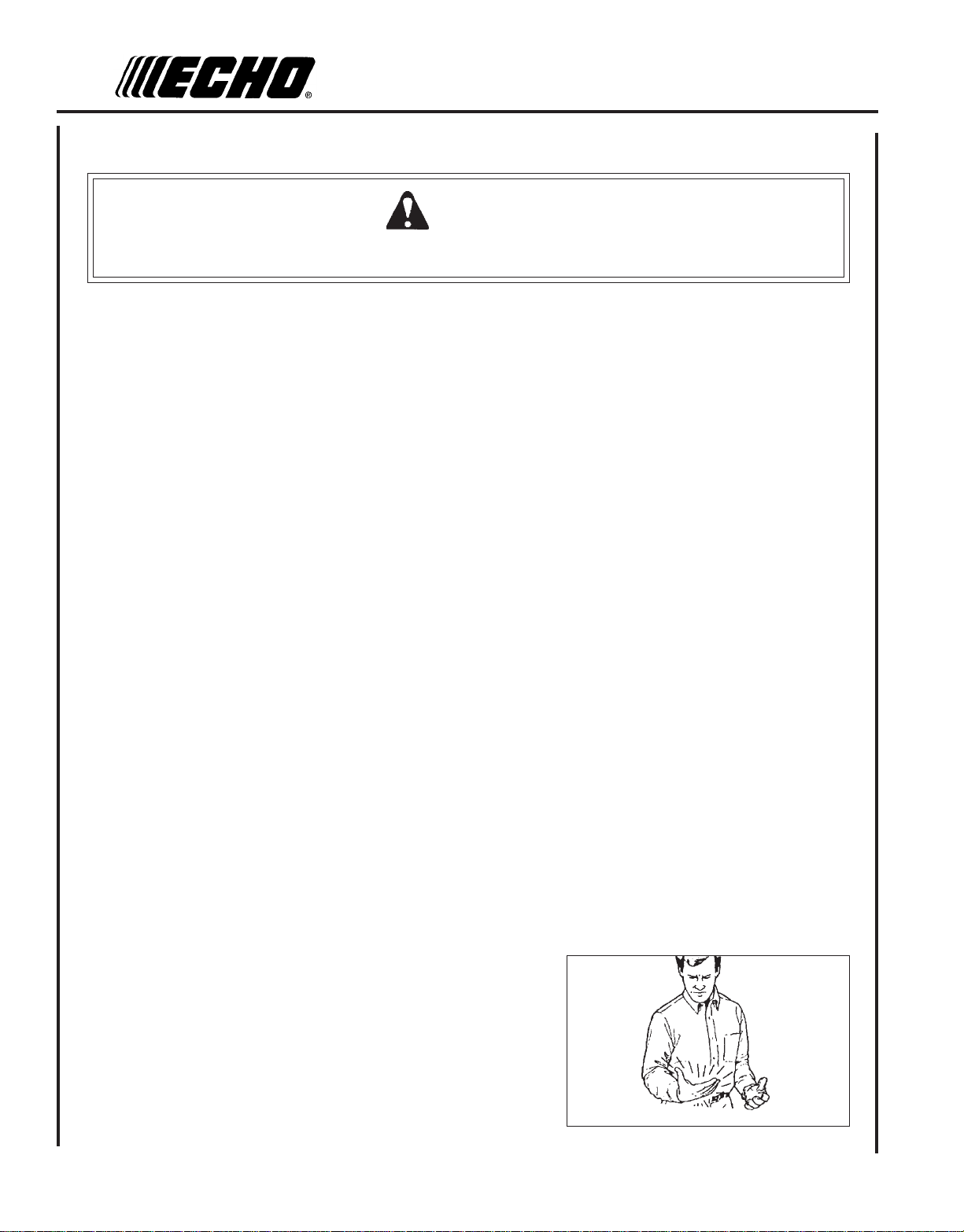
Hand Protection
Wear no-slip, heavy duty work gloves to improve your
grip on the unit handles. Gloves also reduce the transmission of machine vibration to your hands.
Hearing Protection
ECHO recommends wearing hearing protection whenever
unit is used.
Proper Clothing
Wear snug fitting, durable protective clothing; chain saw
safety pants or chaps are recommended.
• Pants should have long legs, shirts with long sleeves.
• DO NOT WEAR SHORTS,
• DO NOT WEAR TIES, SCARVES, JEWELRY.
Wear sturdy protective safety shoes or boots with nonskid soles;
• DO NOT WEAR OPEN TOED SHOES,
• DO NOT OPERATE UNIT BAREFOOTED.
Hot Humid Weather
Heavy protective clothing can increase operator fatigue,
which may lead to heat stroke. Schedule heavy work for
early morning or late afternoon hours when temperatures
are cooler.
Vibration and Cold
It is believed that a condition called Raynaud’s Phenomenon, which affects the fingers of certain individuals may be
brought about by exposure to vibration and cold. Exposure to vibration and cold may cause tingling and burning sensations followed by loss of color and numbness in the fingers. The following precautions are strongly recommended
because the minimum exposure which might trigger the ailment is unknown.
• Keep your body warm, especially the head, neck, feet, ankles, hands
and wrists.
• Maintain good blood circulation by performing vigorous arm
exercises during frequent work breaks and also by not smoking.
• Limit the hours of operation. Try to fill each day with jobs where
operating the unit or other hand-held power equipment is not
required.
• If you experience discomfort, redness, and swelling of the fingers
followed by whitening and loss of feeling, consult your physician
before further exposing yourself to cold and vibration.
Page 5
POWER PRUNER
TM
OPERATOR'S MANUAL
Repetitive Stress Injuries
It is believed that overusing the muscles and tendons of the fingers, hands, arms and shoulders may cause soreness,
swelling, numbness, weakness and extreme pain in those areas. Certain repetitive hand activities may put you at a high
risk for developing a Repetitive Stress Injury (RSI). An extreme RSI condition is Carpal Tunnel Syndrome (CTS), which
could occur when your wrist swells and squeezes a vital nerve that runs through the area. Some believe that prolonged
exposure to vibration may contribute to CTS. CTS can cause severe pain for months or even years.
To reduce the risk of RSI/CTS, do the following:
• Avoid using your wrist in a bent, extended or twisted position.
Instead try to maintain a straight wrist position. Also, when grasping,
use your whole hand, not just the thumb and index finger.
• Take periodic breaks to minimize repetition and rest your hands.
• Reduce the speed and force with which you do the repetitive movement.
• Do exercises to strengthen the hand and arm muscles.
• Immediately stop using all power equipment and consult a doctor if
you feel tingling, numbness or pain in the fingers, hands, wrists or
arms. The sooner RSI/CTS is diagnosed, the more likely permanent
nerve and muscle damage can be prevented.
5
DANGER
All over head electrical conductors and communications wires can
have electricity flow with high voltages. This unit is not insulated
against electrical current. Never touch wires directly or indirectly
when pruning, otherwise serious injury or death may result.
WARNING
Do not operate this product indoors or in inadequately ventilated
areas. Engine exhaust contains poisonous emissions and can cause
serious injury or death.
Read the Manuals
• Provide all operators of this equipment with the Operator's Manual,
and instructions for safe operation.
Clear the Work Area
• Spectators and fellow workers must be warned, and children and
animals prevented from coming nearer than 15 m (50 ft.) while the unit
is in use.
Use Proper Clothing & Equipment
• Always wear head protection with full face shield to help protect
against falling branches and debris.
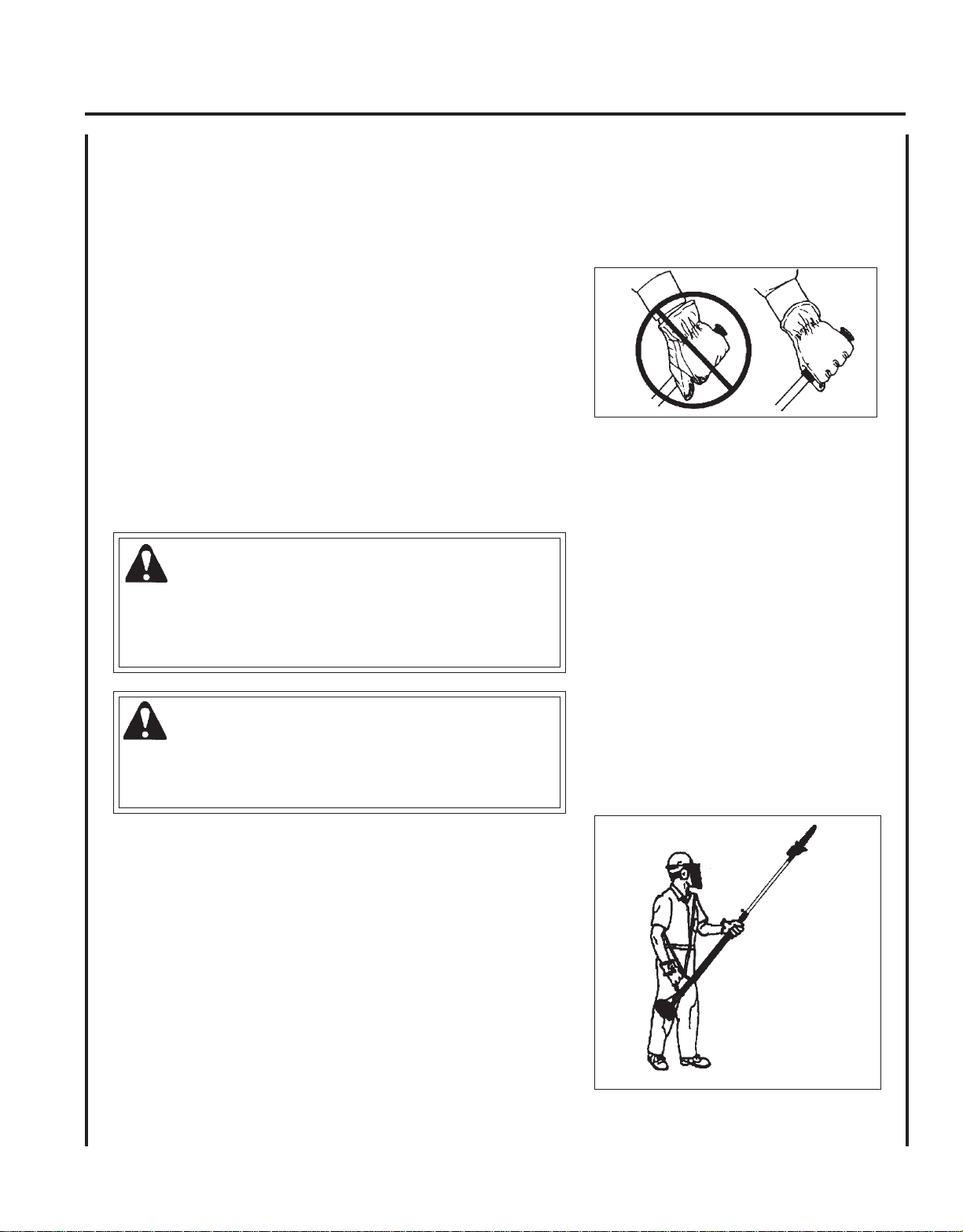
Keep A Firm Grip
• Grip Power PrunerTM with both hands with thumbs and fingers
encircling the handle, and shaft tube.
Page 6
6
Keep A Solid Stance
• Maintain footing and balance at all times. Do not stand on slippery,
uneven or unstable surfaces. Do not work in odd positions or on
ladders. Do not overreach.
• Operate the Power PrunerTM only from the ground or out of an
approved bucket lift.
• Always evaluate the branches to be pruned for hazards such as
loose dead branches which may fall and strike the operator or
helpers. Remove hazards before pruning.
• Plan retreat path from falling objects.
• Cut branches bounce when striking ground.
• Check that shoulder harness is adjusted for safe, comfortable
operation. See picture at right for proper adjustment.
• Turn the Power PrunerTM off when moving from tree to tree.
• Avoid any contact with saw chain.
Avoid Hot Surfaces
• Keep exhaust area clear of flammable debris. Avoid contact during
and immediately after operation.
KICKBACK
WARNING
Kickback can lead to dangerous loss of control of the Power PrunerTM and result in serious injury to the operator or
any one standing close by. Hold the Power PrunerTM firmly with both hands with thumbs and fingers encircling the
front and rear handles. Be aware of the down and outward path the pruner will take after the cut is made.
Kickback may occur when the moving saw chain at the nose or tip of
the guide bar touches an object, or when the wood closes in and
pinches the saw chain in the cut. In some cases this may cause a
lightning-fast reverse action, kicking the guide bar and saw chain up
and back or down and back towards the operator. Either of these
reactions may cause the operator to lose control of the Power Pruner
which could result in serious personal injury.
With a basic understanding of kickback, you can reduce or eliminate the
element of surprise which contributes to accidents.
Avoid contact of the guide bar tip with any object while the saw chain
is moving.
Cut only wood. Avoid striking concrete, metal, wire, or other obstructions which could cause kickback or damage to the saw chain.
If the saw chain does strike a foreign object, immediately stop the
engine, inspect and repair the Power PrunerTM if necessary.
TM
Page 7
POWER PRUNER
TM
OPERATOR'S MANUAL
EQUIPMENT
WARNING
Serious injury may result from the use of non approved guide bar and saw chain combinations. ECHO, INC. will not
be responsible for the failure of cutting devices or accessories which have not been tested and approved by ECHO
for use with this unit. Read and comply with all safety instructions listed in this manual.
• Check unit for loose/missing nuts, bolts, and screws. Tighten and/or replace as needed.
• Inspect fuel lines, tank, and area around carburetor for fuel leaks. DO NOT operate unit if leaks are found.
Guide Bar and Saw Chain
• Check that the cutting attachment, guide bar, and saw chain is firmly attached and in safe operating condition.
• Use only one Echo-approved extension on the pruner.
• Do not hit rocks, stones, tree stumps, and other foreign objects with the saw chain.
• Do not cut into the ground with the saw chain.
• If cutting attachment end strikes an obstruction, stop engine immediately and inspect saw chain for damage.
7
• Do not operate with a dull, fractured, or discolored saw chain.
• Remove all foreign objects from work area.
• Always cover the guide bar and saw chain with guide bar cover during transportation and for storage.
EMISSION CONTROL
EPA Phase 2 / C.A.R.B. TIER III
The emission control system for the engine is EM/TWC (Engine Modification and 3-way Catalyst) and for the fuel tank
the Control System is EVAP (Evaporative Emissions). Evaporative emission may be applicable to California models only.
ENGINE FAMILY: 7EHXS.0254KA DISPLACEMENT: 25.4 CC
IMPORTANT ENGINE INFORMATION
EMISSION COMPLIANCE PERIOD : 300 HRS.
THIS ENGINE MEETS U.S. EPA PHASE 2 EMISSION
REGULATIONS FOR SMALL NONROAD ENGINES. REFER TO
OWNER'S MANUAL FOR MAINTENANCE SPECIFICATIONS
AND ADJUSTMENTS.
An Emission Control Label is located on the engine. (This is an EXAMPLE ONLY, information on label varies by engine
FAMILY).
IMPORTANT ENGINE INFORMATION
ENGINE FAMILY: 7EHXS.0254KA DISPLACEMENT: 25.4 CC
EMISSION COMPLIANCE PERIOD : 300 HRS.
THIS ENGINE MEETS U.S. EPA PH2 EXH AND 2007 AND
LATER CALIFORNIA EXH AND EVAP EMISSION REGULATIONS FOR S.O.R.E. REFER TO OWNER'S MANUAL FOR
MAINTENANCE SPECIFICATIONS AND ADJUSTMENTS.
PRODUCT EMISSION DURABILITY
The 300 hour emission durability compliance period is the time span selected by the manufacturer certifying the
engine emissions output meets applicable emissions regulations, provided that approved maintenance procedures
are followed as listed in the Maintenance Section of this manual.
Page 8
8
DESCRIPTION
Locate this safety decal on your unit. Make sure the decals are legible and that you understand and follow the instructions on them. If a decal cannot be read, a new one can be ordered from your ECHO dealer. See PARTS ORDERING
instructions for specific information.
13
21
20
19
18
17
Hot Decal (near muffler)
P/N 89016006361
14
7
6
Engine Cover
P/N 89016022660
16
8
9
5
4
3
15
10
11
12
1
2
22
Page 9

POWER PRUNER
TM
OPERATOR'S MANUAL
1. POWER HEAD - Includes the Engine, Clutch, Fuel System, Ignition System and Starter.
2. THROTTLE TRIGGER - Spring loaded to return to idle when released. During acceleration press trigger gradually
for best operating technique.
3. SHOULDER HARNESS - An adjustable strap that suspends the unit from the operator.
4. CUTTING ATTACHMENT - Sealed, gear ratio is 1.5:1 reduction.
5. CUTTING SHOE - Used to capture and stabilize branch while cutting. Place cutting shoe against branch, accelerate
and lower saw chain into branch.
6. GUIDE BAR - 305 mm (12 in.) guide bar w/chain tensioner.
7. SAW CHAIN - 91, 9.53 mm (3/8 in.) pitch, 0.050 gauge low profile Oregon® saw chain. Runs approximately 609.6 m/
min. (2000 ft/min) at full throttle.
8. AUTOMATIC OILER ASSEMBLY - Self oiling. Use high quality, low viscosity, non detergent bar and chain oil.
9. LOWER SHAFT TUBE - Durable fiberglass mesh housing.
10. STOP SWITCH - Mounted on top of handle assembly. Move switch forward to run, back to stop.
9
11. THROTTLE TRIGGER LOCKOUT - This lever must be depressed before throttle trigger can be operated.
12. REAR HANDLE ASSEMBLY - Sturdy handle for right hand placement. Includes stop switch and throttle trigger.
13. TOP GUARD - Protects arm from hot engine.
14. SPARK ARRESTOR - CATALYTIC MUFFLER / MUFFLER -The muffler or catalytic muffler controls exhaust noise
and emission. The spark arrestor screen prevents hot, glowing particles of carbon from leaving the muffler. Keep
exhaust area clear of flammable debris.
15. FUEL TANK - Contains fuel and fuel filter.
16. FUEL TANK CAP - Covers and seals fuel tank opening.
17. PURGE BULB - Pumping purge bulb before starting engine draws fresh fuel from the fuel tank, purging air from the
carburetor. Pump purge bulb until fuel is visible and flows freely in the clear fuel tank return line. Pump purge bulb
an additional 4 or 5 times.
18. RECOIL STARTER - Pull recoil handle slowly until starter engages, then quickly and firmly. When engine starts
return handle slowly. DO NOT let handle snap back or damage will occur.
19. AIR CLEANER ASSEMBLY - Contains replaceable air filter element.
20. CHOKE - Located above air cleaner housing. Move lever to starting position ( ) (close choke) and back to run
position ( ) (open choke).
21. SPARK PLUG - Provides spark to ignite fuel mixture.
22. GUIDE BAR COVER - Used to cover guide bar and saw chain during transport and storage. Remove guide bar
cover before using unit.
Page 10
10
CONTENTS
Due to packaging restriction the ECHO product you have purchased requires some assembly.
After opening the carton, check for damage. Immediately notify your retailer or ECHO Dealer of damaged or missing
parts. Use the contents list to check for missing parts.
__ Power Head
__ Drive Shaft Assembly
__ Cutting Attachment W/ Guide Bar and Saw Chain
__ Operator's Manual
__ Safety Manual
__ Warranty Registration Card
__ Warranty Statement
__ T-Wrench (combination screwdriver/spark plug socket)
__ 4 mm hex wrench
__ Safety Glasses
__ Echo Power Blend TM 2-stroke oil sample
__ Shoulder Harness
__ Guide Bar Cover
ASSEMBLY
Tools Required: 10x19mm (13/32x3/4in) T-wrench, 4 mm Hex
Wrench, 8 x 10mm Wrench
Parts Required: Power Head, Drive Shaft Assembly,
Cutting Attachment
DRIVE SHAFT / POWER HEAD
1 . Loosen bolt (A).
2 . Remove protective cap from drive shaft end.
3 . Align flexible drive shaft coupler (B) with engine socket and slide
together until engine rests against lower drive shaft adapter (C).
IMPORTANT
Painted end of flexible drive shaft coupler must always be
installed in engine socket when assembling engine to drive shaft.
4 . Rotate lower drive shaft to align engine and rear handle assembly in
an upright position.
A
B
C
5 . Tighten bolt (A) securely so engine will not rotate on lower shaft
tube.
A
Page 11
POWER PRUNER
TM
OPERATOR'S MANUAL
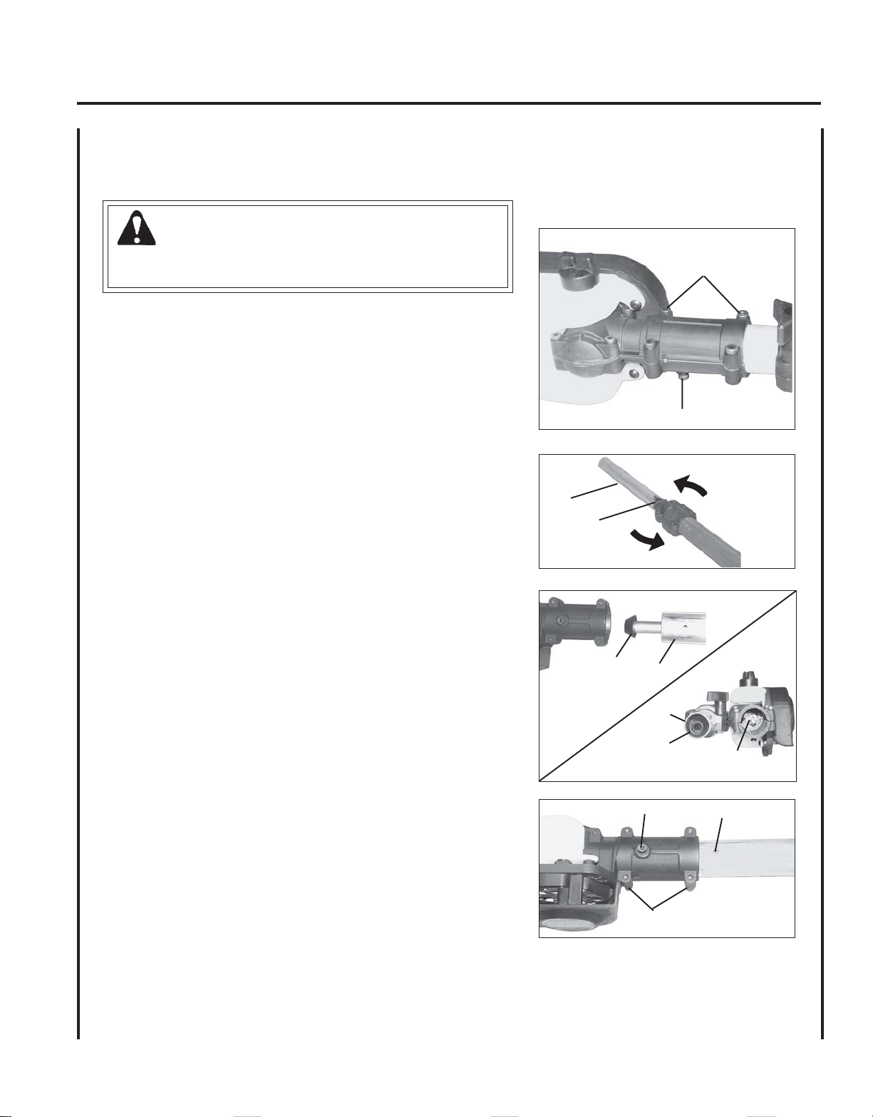
CUTTING ATTACHMENT TO DRIVE SHAFT INSTALLATION
WARNING
Saw Chain is sharp! Always wear gloves when handling assembly,
otherwise serious personal injury may result.
1 . Loosen the four (4) screws (D) and locator screw (E) on cutting
attachment.
2 . Loosen center clamp knob (F) turning counter clockwise.
G
3 . Pull upper tube (G) out of fiberglass lower tube 127-152 mm (5-6 in.),
then slide (G) back into fiberglass lower tube exposing inner drive
shaft (H). Align and join star shaped drive end of inner drive shaft
(H) with cutting attachment shaft (I).
11
D
E
F
4 . Align ridges on upper tube (G) with seams in cutting attachment.
5 . Slide together aligning locator screw (E) in cutting attachment with
locating hole (J) in upper tube.
6 . Tighten locator screw (E). Tighten four (4) cutting attachment
screws (D).
7 . Extend upper tube to desired length. Tighten center clamp knob (F)
turning clockwise.
H
G
G
H
E
D
I
J
Page 12

12
THROTTLE LINKAGE AND IGNITION LEADS
1 . Close choke and remove air filter and cover.
2 . Place inner cable in slot of carburetor swivel (B).
3. Loosen nut (A) and place threaded end of throttle linkage in
bracket slot. Finger tighten nut (A).
4 . Check throttle for freedom of movement and that wide open throttle
/ low idle extremes are adjusted properly. If adjustment cannot be
achieved with adjusting nuts, consult with your Echo Dealer for
correct adjustment procedure.
5 . Tighten nut (A). Connect 2 ignition leads from throttle cable tubing
to 2 ignition leads (C) and (D) on engine.
6. Bundle and secure ignition leads against engine housing with clip
(E).
7 . Install air filter and cover.
SAW CHAIN TENSION ADJUSTMENT
C
B
A
D
E
W ARNING
Always disconnect spark plug wire before servicing cutting
attachment. Wear gloves when handling saw chain, otherwise
serious personal injury may result.
To Adjust Saw Chain Tension.
1 . Loosen two (2) 6 mm (13/32 in.) guide bar nuts (A) located on
cutting attachment.
2 . Turn the adjuster slot (B) clockwise until saw chain touches the
bottom of guide bar. Turning adjuster slot (B) counter clockwise
will loosen saw chain on guide bar.
3 . Tighten guide bar nuts firmly. Move saw chain backwards on
guide bar by hand. Saw chain should move freely on guide bar if it
is in proper mesh with sprocket. If saw chain is difficult to rotate or
binds on guide bar, it is too tight.
Keep the saw chain lubricated and properly adjusted and the guide bar
nuts tightened firmly at all times.
B
A
Page 13

POWER PRUNER
TM
OPERATOR'S MANUAL
OPERATION
NOTICE: Use of unmixed, improperly mixed, or fuel older than 90 days, (stale fuel), may cause hard starting, poor
performance, or severe engine damage and void the product warranty. Read and follow instructions in the Storage
section of this manual.
FUEL
WARNING
Alternative fuels, such as E-20 (20% ethanol), E-85 (85% ethanol) or any fuels not meeting ECHO requirements are
NOT approved for use in ECHO 2-stroke gasoline engines. Use of alternative fuels may cause performance problems, loss of power, overheating, fuel vapor lock, and unintended machine operation, including, but not limited to,
improper clutch engagement. Alternative fuels may also cause premature deterioration of fuel lines, gaskets,
carburetors and other engine components.
Fuel Requirements
Gasoline - Use 89 Octane [R+M/2] (mid grade or higher) gasoline known to be good quality. Gasoline may contain up to
10% Ethanol (grain alcohol) or 15% MTBE (methyl tertiary-butyl ether). Gasoline containing methanol (wood alcohol) is
NOT approved.
13
Two Stroke Oil - A two-stroke engine oil meeting ISO-L-EGD (ISO/CD 13738) and J.A.S.O. FC Standards must be used.
Echo brand premium Power Blend TM Universal 2-Stroke Oil meets these standards. Engine problems due to inadequate
lubrication caused by failure to use an ISO-L-EGD and J.A.S.O. FC certified oil, such as Echo premium Power Blend TM,
will void the two-stroke engine warranty. (Emission related parts only are covered for two years, regardless of twostroke oil used, per the statement listed in the Emission Defect Warranty Explanation.)
IMPORTANT
Echo premium Power Blend TM Universal 2-Stroke Oil may be mixed at 50:1 ratio for application in all Echo engines
sold in the past regardless of ratio specified in those manuals.
Handling Fuel
DANGER
Fuel is VERY flammable. Use extreme care when mixing, storing or handling or serious personal injury may result.
• Use an approved fuel container.
• DO NOT smoke near fuel.
• DO NOT allow flames or sparks near fuel.
• Fuel tanks/cans may be under pressure. Always loosen fuel caps slowly allowing pressure to equalize.
• NEVER refuel a unit when the engine is HOT or RUNNING!
• DO NOT fill fuel tanks indoors. ALWAYS fill fuel tanks outdoors over bare ground.
• DO NOT overfill fuel tank. Wipe up spills immediately.
• Securely tighten fuel tank cap and close fuel container after refueling.
• Inspect for fuel leakage. If fuel leakage is found, do not start or operate unit until leakage is repaired.
• Move at least 3m (10 ft.) from refueling location before starting the engine.
Page 14

14
Mixing Instructions
1 . Fill an approved fuel container with half of the required amount of
gasoline.
2. Add the proper amount of 2-stroke oil to gasoline.
3 . Close container and shake to mix oil with gasoline.
4 . Add remaining gasoline, close fuel container, and remix.
IMPORTANT
Spilled fuel is a leading cause of hydrocarbon emissions. Some
states may require the use of automatic fuel shut-off containers
to reduce fuel spillage.
After use
• DO NOT store a unit with fuel in its tank. Leaks can occur. Return
unused fuel to an approved fuel storage container.
Storage - Fuel storage laws vary by locality. Contact your local
government for the laws affecting your area. As a precaution, store fuel
in an approved, airtight container. Store in a well-ventilated, unoccupied building, away from sparks and flames.
.S.UCIRTEM
SAGLIOSAGLIO
snollaG.zo.lFretiL.cc
1
2
5
6.2
2.5
31
4
8
02
oitaR1:05-xiMliOotleuF
08
061
004
IMPORTANT
Stored fuel ages. Do not mix more fuel than you expect to use in
thirty (30) days, ninety (90) days when a fuel stabilizer is added.
IMPORTANT
Stored two-stroke fuel may separate. ALWAYS shake fuel
container thoroughly before each use.
Page 15
POWER PRUNER
TM
OPERATOR'S MANUAL
LUBRICATING THE GUIDE BAR AND SA W CHAIN
Automatic Oiling System
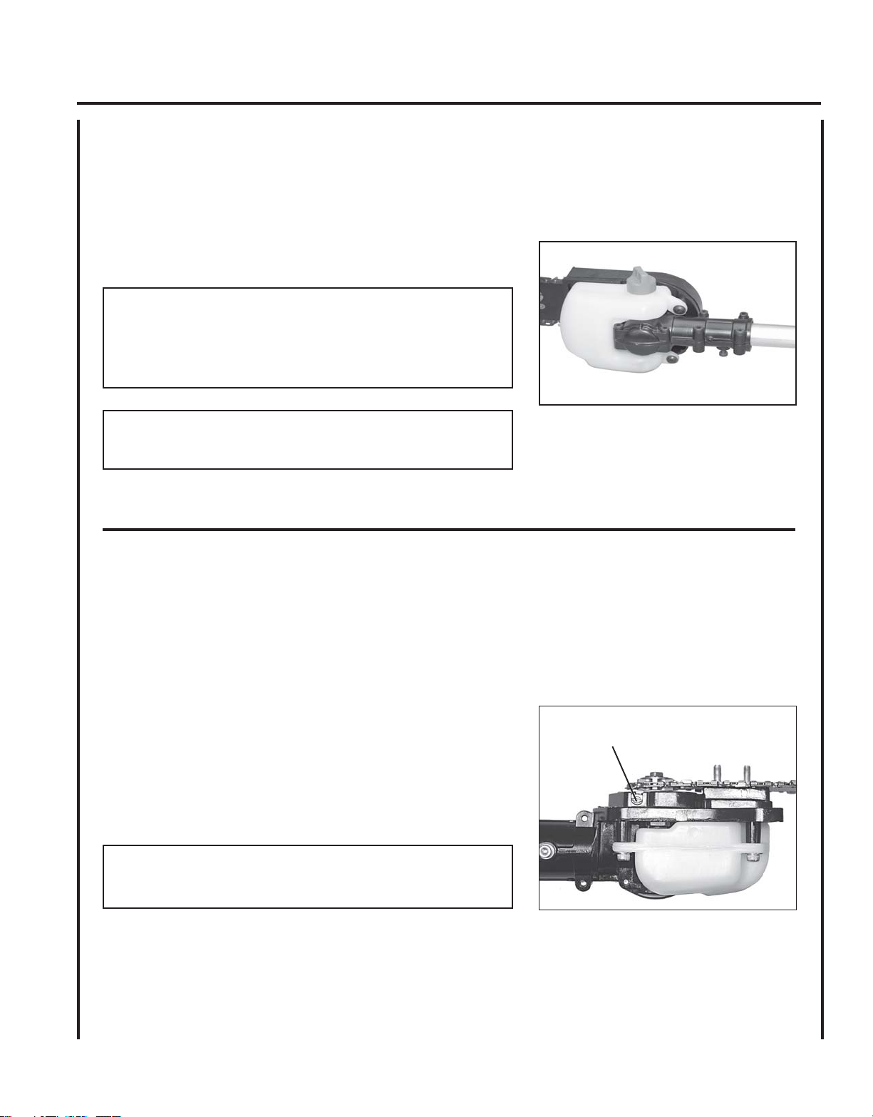
1 . Wipe debris from around oil fill cap.
2 . Remove oil fill cap and fill reservoir with a quality, low viscosity
guide bar and saw chain oil.
NOTE
The discharge volume of the automatic oiler is preset to deliver 3 to
4 cc/min. at normal operating RPM. During heavy or dry cutting
conditions the oil discharge volume may be adjusted to assure
adequate lubrication. Refill the oil reservoir with each tank of fuel.
IMPORTANT
To prevent plastic deterioration, do not use synthetic or silicone
based oil.
15
ADJUSTING AUTOMATIC OILER
Tools required: 10x19mm (13/32x3/4) T-Wrench
1 . Remove two (2) 6 mm guide bar retaining nuts and sprocket cover.
2 . From bottom of gear case, turn adjustment screw (A) clockwise to
decrease oil volume - counter clockwise to increase oil volume.
NOTE
Very little visible oil on the saw chain will provide sufficient
lubrication.
3. Assemble components in reverse order.
A
Page 16
16
STARTING COLD ENGINE
W ARNING
The attachment will operate immediately when the engine starts and
could result in loss of control and possible serious injury. Keep
movable parts of the attachment off the ground and away from
objects that could become entangled or thrown.
1. Stop Switch
Move stop switch button (A) forward away from the STOP
position.
2. Choke
Move choke (B) to “Cold Start” ( ) Position.
A
B
3. Purge Bulb
Pump purge bulb (C) until fuel is visible and flows freely in the clear
fuel tank return line. Pump bulb an additional 4 or 5 times.
4. Recoil Starter
Lay the unit on a flat, area and keep movable attachment parts clear
of all obstacles. Firmly grasp right hand grip and throttle trigger
lockout with left hand and fully depress throttle trigger to wide
open position. Rapidly pull recoil starter handle/rope (D) until
engine fires (or maximum five [5] pulls).
5. Choke
After engine fires (or five [5] pulls), move choke lever back to
“Run” ( ) position. Hold throttle trigger and throttle trigger
lockout fully depressed and pull recoil starter handle/rope until
engine starts and runs. Release throttle trigger and allow unit to
warm up at idle for several minutes.
NOTE
If engine does not start with choke in “Run” position after 5 pulls,
repeat instructions 2 - 5.
D
C
6 . After engine warms up, gradually depress throttle trigger to
increase engine RPM to operating speed.
Page 17

POWER PRUNER
TM
STARTING WARM ENGINE
The starting procedure is the same as Cold Start except DO NOT close
the choke, and do not depress throttle trigger to wide open position.
W ARNING
The attachment should not move at idle, otherwise serious personal
injury may result.
NOTE
If attachment moves, readjust carburetor according to “Carburetor
Adjustment” instructions in this manual or see your ECHO Dealer.
1. Stop Switch.
Move Stop Switch button (A) forward away from the STOP
position.
OPERATOR'S MANUAL
A
17
2. Purge Bulb
Pump purge bulb (C) until fuel is visible and flows freely in the clear
fuel tank return line. Pump bulb an additional 4 or 5 times.
3. Recoil Starter.
Lay the unit on a flat, clear area and firmly grasp right hand grip
with left hand. Do not depress throttle trigger. Pull the recoil
starter handle (D) until the engine fires.
NOTE
If engine does not start after 5 pulls, use Cold Start Procedure.
D
C
Page 18
18
STOPPING ENGINE
1. Throttle.
Release throttle trigger, and allow engine to return to idle before
stopping engine.
2. Stop Switch.
Move stop switch button (A) backward to STOP position.
W ARNING
If engine does not stop when stop switch is moved to STOP
position, close choke - COLD START position - to stall engine.
Have your ECHO dealer repair stop switch before using pruner
again.
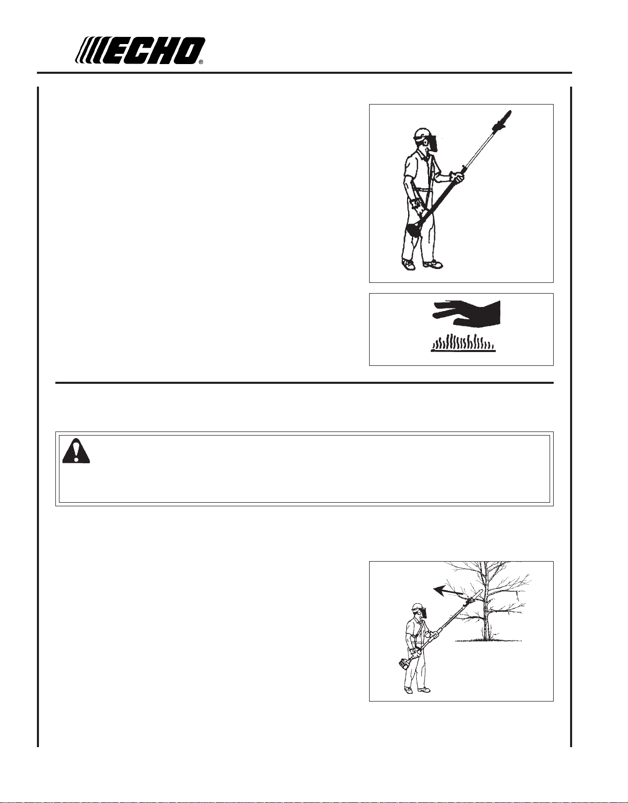
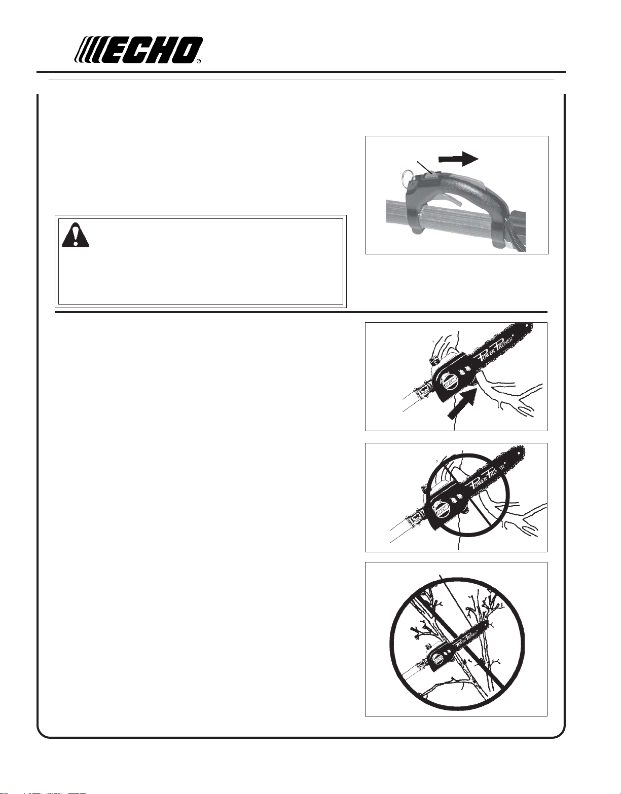
PRUNING TECHNIQUES
The Power PrunerTM is designed for light to medium trimming of limbs
and branches up to 203 mm (8 in.) in diameter. Follow these tips for
successful operation.
A
CORRECT
• Plan cut carefully. Check direction branch will fall.
• Plan retreat path from falling branch. Cut branches bounce when
striking ground.
• Long branches should be removed in several pieces.
• Do not stand directly beneath branch being cut.
• When ready to cut:
Hold "cutting shoe" against branch. This will prevent whipping of the
branch. DO NOT use back and forth sawing action.
• Look out for branch immediately behind the branch being cut. If saw
chain hits rear branch damage to saw chain may occur.
• Accelerate to full throttle.
• Apply cutting pressure.
• Ease cutting pressure when nearing end of cut to maintain control.
• When pruning a limb 102 mm (4 in.) diameter or larger cut as follows:
1 . Under cut 1/4 limb diameter near tree trunk.
2 . Finish top cut slightly farther out on limb.
3. Flush cut stub at trunk.
GUIDE AGAINST
BRANCH
NOT
CORRECT
BLADE HITS REAR BRANCH
• DO NOT use for felling or bucking.
NOT
CORRECT
Page 19

POWER PRUNER
TM
OPERATOR'S MANUAL
19
MAINTENANCE
Your ECHO Power PrunerTM is designed to provide many hours of trouble free service. Regular scheduled maintenance
will help your pruner achieve that goal. If you are unsure or are not equipped with the necessary tools, you may want to
take your unit to an ECHO Service Dealer for maintenance. To help you decide whether you want to DO-IT-YOURSELF
or have the ECHO Dealer do it, each maintenance task has been graded. If the task is not listed see your ECHO Dealer for
repairs.
SKILL LEVEL
Level 1 = Easy to do. Most required tools come with unit.
Level 2 = Moderate difficulty. Some specialized tools may be required.
Level 3 = Experience required. Specialized tools are required. ECHO recommends
that the unit be returned to your ECHO dealer for service.
ECHO offers REPOWERTM Maintenance Kits and Parts to make your maintenance job easier. Just below each task
heading are listed the various part numbers required for that task. See your ECHO dealer for these parts.
MAINTENANCE INTERVALS
/TNENOPMOC
METSYS
ECNANETNIAM
ERUDECORP
D'QER
LLIKS
LEVEL
ROYLIAD
EROFEB
ESU
YREVE
LEUFER
3
SHTNOM
09RO
SRUOH
6
SHTNOM
072RO
SRUOH
006
YLRAEY
SRUOH
serudecorPecnanetniaMrelaeDohcEdednemmoceR
troPtsuahxErednilyCnobraceD/naelC/tcepsnI 3 C/I
etniaMflesruoY-tI-oD
retliFriAecalpeR/naelC/tcepsnI 1 C/I*I
metsySekohCnaelC/tcepsnI 2 C/I
retliFleuFecalpeR/tce
skael,metsySleuFecalpeR/tcepsnI 1 *)1(R/I)1(I)1(I
metsySgnilooCnaelC/tcepsnI 2 C/I
MecalpeR/tcepsnI 2 *R/I
gnisuoHtfahSevirDnaelC/tcepsnI 2 C/II
raBediuGetacirbuL/naelC/tcepsnI 2 *C/II
niahCwaS/ecalp
epoRretratSlioceRnaelC/tcepsnI 1 *R/I
gulPkrapSnaelC/tcepsnI 2 C/I*R
psnI 1 I*R/I
rotserrAkrapSrelffu
etacirbuL
eR/neprahS/tcepsnI
2 *R/II
serudecorPecnan
N/swercSecalpeR/nethgiT/tcepsnI 1 *R/I
)1( .ytirgetninoissimeniatniamotecnanetniamralugereriuqerTONODsknatleufevitaropavewoL
* .noitcepsnigniru
stloB/stu
-ETONTNATROPMI deriuqerfoycneuqerfehtenimretedlliwecneirepxeruoydnaesulaut
.ecnanetniam
:SETONERUDECORPECNANETNIAM
SEDOCRETTELERUDECORPECNANETNIAM NAELC=C,ECALPER=R,TCEPSNI=I:
cA.mumixameranwohsslavretniemiT
draewroegamadfognidnifehtnodesaberaecalperotsnoitadnemmocerllA
Page 20
20
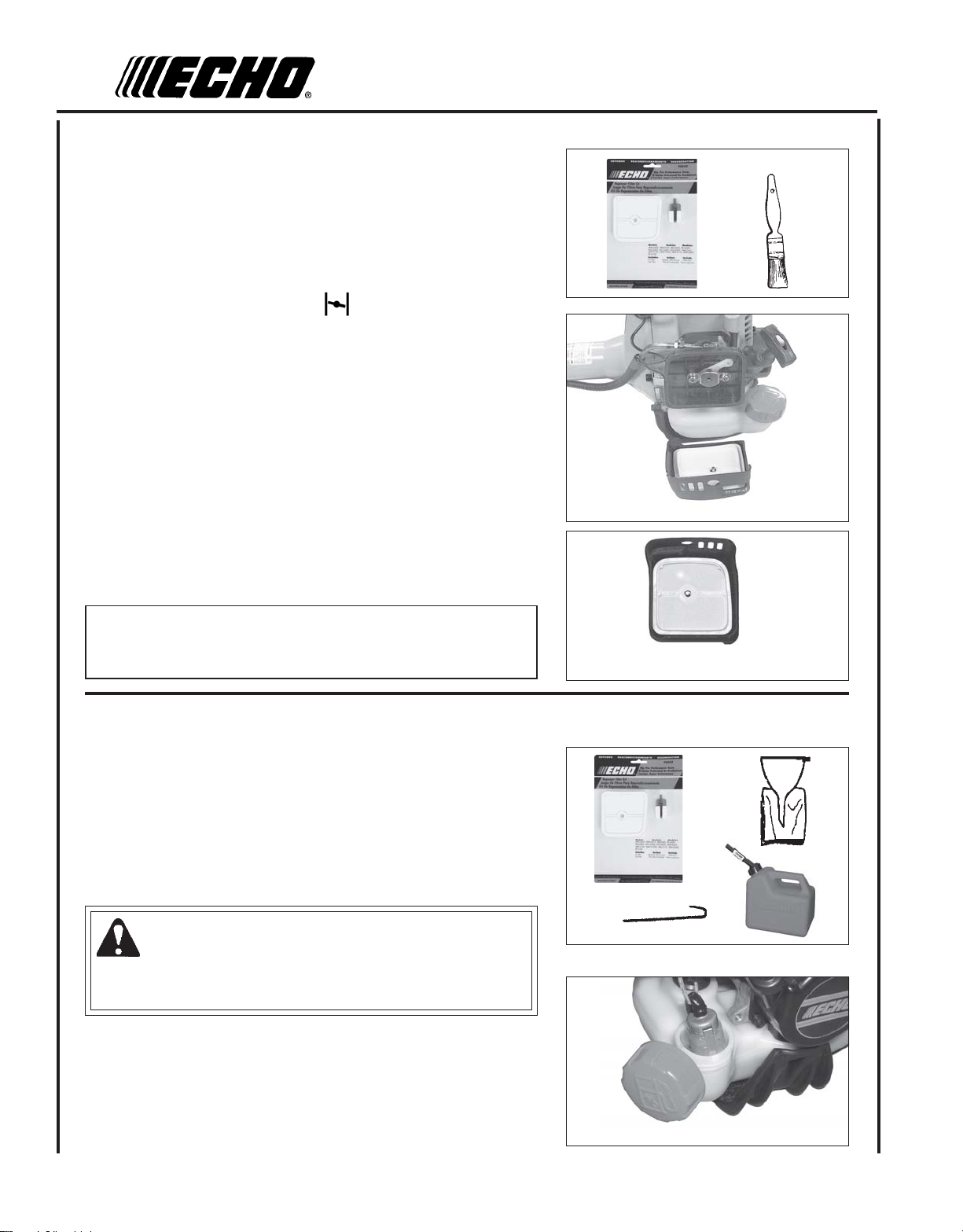
AIR FILTER
Level 1.
Tools required: Cleaning brush 25 or 50 mm (1 or 2 in.)
Parts required: 90030 REPOWERTM Air and Fuel Filter Kit
1 . Close choke (Cold Start Position [ ]). This prevents dirt from
entering the carburetor throat when the air filter is removed. Brush
accumulated dirt from air cleaner area.
2 . Remove air filter cover. Brush dirt from inside cover.
3 . Remove air filter and lightly brush debris from filter. Replace filter if
it is damaged, fuel soaked, very dirty, or the rubber sealing edges
are deformed.
4 . If filter can be reused, be certain it:
• Fits tightly in the air filter cavity.
• Is installed with the original side out.
5 . Install air filter cover.
NOTE
Carburetor adjustment may be needed after air filter cleaning/
replacement. See Carburetor Adjustment Section.
FUEL FILTER
Level 1.
Tools required: 200-250 mm (8 - 10 in.) length of wire with one end
bent into a hook, Clean rag, funnel, and an approved
fuel container
Parts Required: 90030 REPOWERTM Air and Fuel Filter Kit
DANGER
Fuel is VERY flammable. Use extreme care when mixing, storing or
handling or serious personal injury may result.
1 . Use a clean rag to remove loose dirt from around fuel cap and
empty fuel tank.
2 . Use the “fuel line hook” to pull the fuel line and filter from the tank.
3 . Remove the filter from the line and install the new filter.
Page 21
POWER PRUNER
TM
OPERATOR'S MANUAL
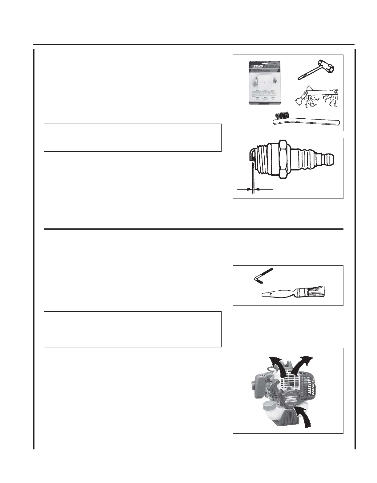
SPARK PLUG
Level 2.
Tools required: 10x19mm (13/32x3/4in) T-wrench, Feeler gauge,
Soft metal brush
Parts Required: REPOWERTM Tune-Up Kit P/N 90075
IMPORTANT
Use only NGK BPM-8Y spark plug (BPMR-8Y in Canada)
otherwise severe engine damage may occur.
1 . Remove spark plug and check for fouling, worn and rounded center
electrode.
2 . Clean the plug or replace with a new one. DO NOT sand blast to
clean. Remaining sand will damage engine.
3 . Adjust spark plug gap 0.65mm (0.026 in.) by bending outer electrode.
21
0.65 mm
(0.026 in.)
4 . Tighten spark plug to 150-170 kg/cm (130-150 in. lb.).
COOLING SYSTEM CLEANING
Level 2.
Tools required: 4 mm Hex wrench, Cleaning brush 25 - 50 mm
(1 - 2 in.)
Parts Required: None.
IMPORTANT
To maintain proper engine operating temperatures, cooling air must
pass freely through the cylinder fin area. This flow of air carries
combustion heat away from the engine.
Overheating and engine seizure can occur when:
• Air intakes are blocked, preventing cooling air from reaching the
cylinder.
• Dust and grass build up on the outside of the cylinder. This build up
insulates the engine and prevents the heat from leaving.
Removal of cooling passage blockages or cleaning of cooling fins is
considered “Normal Maintenance.” Any failure attributed to lack of
maintenance is not warranted.
Page 22

22
1 . Remove spark plug lead.
2 . Remove two (2) muffler cover screws and muffler cover (A).
3 . Remove screw and arm rest (B).
4 . Remove engine cover (C).
IMPORTANT
DO NOT use a metal scraper to remove dirt from the cylinder fins.
5 . Use brush to remove dirt from the cylinder fins.
6 . Remove grass and leaves from the grid between the recoil starter
and fuel tank.
C
B
A
7. Assemble components in reverse order.
EXHAUST SYSTEM
Spark Arrestor Screen
Level 2.
Tools Required: Cross Head Screwdriver, Soft Metal Brush,
4 mm Hex Wrench
Parts Required: Spark Arrestor Screen, Gasket
Page 23

POWER PRUNER
TM
OPERATOR'S MANUAL
1 . Remove spark plug lead.
2 . Remove muffler cover (A).
3 . Place piston at Top Dead Center (TDC) to prevent carbon/dirt from
entering cylinder.
4 . Remove spark arrestor screen cover (B), gasket (C), and screen (D)
from muffler body.
5 . Clean carbon deposits from muffler components.
NOTE
When cleaning carbon deposit, be careful not to damage the
catalytic body.
6 . Replace screen if it is cracked, plugged or has holes burned
through.
7. Assemble components in reverse order.
23
A
D
B
C
Cylinder Exhaust Port
Level 3.
IMPORTANT
The cylinder exhaust port must be inspected and cleaned of excess
carbon every 3 months or 90 hours of operation in order to maintain
this engine within the emissions durability period. ECHO strongly
recommends that you return your unit to your ECHO dealer for this
important maintenance service.
CARBURETOR ADJUSTMENT
Engine Break-In
New engines must be operated a minimum duration of two tanks of fuel
break-in before carburetor adjustments can be made. During the break-in
period your engine performance will increase and exhaust emissions will
stabilize. Idle speed can be adjusted as required.
High Altitude Adjustment
This engine has been factory adjusted to maintain satisfactory starting,
emission, and durability performance up to 1,000 feet above mean sea
level (MSL). To maintain proper engine operation above 1,000 feet MSL
the carburetor must be adjusted by an authorized ECHO service dealer.
IMPORTANT
If the engine is adjusted for operation above 1,000 feet MSL, the
carburetor must be re-adjusted when operating the engine below
1,000 feet MSL, otherwise severe engine damage can result.
Page 24

24
Level 2.
Tools required: Screwdriver, Tachometer (ECHO P/N 99051130017).
Parts required: None.
NOTE
Every unit is run at the factory and the carburetor is set in compliance with emission regulations. This carburetor does not have
acceleration and high speed adjustment needles.
1 . Check idle speed and reset if necessary. If a tachometer is avail-
able, idle speed screw (A) should be set to the specifications found
on page 29 "Specifications" of this manual. Turn idle screw (A)
clockwise to increase idle speed; counter clockwise to decrease
idle speed.
W ARNING DANGER
When carburetor adjustment is completed, the cutting attachment should not turn at idle, otherwise serious personal injury
may result.
A
Page 25

POWER PRUNER
TM
OPERATOR'S MANUAL
GUIDE BAR AND SA W CHAIN REPLACEMENT
WARNING
Never try to replace or adjust guide bar and saw chain with engine running. Always disconnect spark plug wire
before servicing guide bar and saw chain. This saw chain is VERY sharp, wear heavy gloves to protect your hands
when handling it. Wear eye protection meeting CE or ANSI specification Z87.1.
Guide Bar Replacement / Installation
Level 2
Tools Required: 10 x 19 mm (13/32 x 3/4 in.) T-wrench
C
1 . Remove two (2) 6 mm guide bar nuts (A), and turn saw chain
tension adjustment slot (B) counterclockwise to release tension.
2 . Remove sprocket cover (C).
A
B
25
3 . Remove guide bar and saw chain from gear case and sprocket.
4 . Remove chain from guide bar and check guide bar for damage and
excessive or uneven wear. Replace guide bar if necessary.
5 . Turn saw chain tension adjuster slot (B) counterclockwise until it
stops.
6. Install chain on guide bar with cutters on top of bar facing toward
bar tip.
7. Install guide bar and chain on gear case, engaging chain with drive
sprocket (D).
8 . Turn tension adjustment slot clockwise to take up slack in saw
chain.
9 . Install sprocket guard (C), and tighten guide bar nuts finger tight.
10. Adjust chain tension.
D
C
A
B
B
Page 26
26
To Adjust Saw Chain Tension.
1. Loosen two guide bar nuts (A), if necessary.
2 . Turn saw chain adjuster slot (B) clockwise to tighten saw chain on
guide bar. Turning slot counter clockwise will loosen saw chain on
guide bar.
3 . Tighten guide bar nuts (A) firmly. Pull the saw chain around the
guide bar by hand. Saw chain should move freely on guide bar. If
saw chain is difficult to rotate or binds on guide bar, it is too tight.
4. Keep the saw chain lubricated and properly adjusted and the
guide bar nuts tightened firmly at all times.
Standard Bar and Chain Combinations
Bar P/N Chain P/N chain type links pitch gauge
PPF-210
PPT-230
99944200530
PPT-260
10" Intenz™ bar
1102373901
12" Intenz™ bar
1122374401
1917039 91 39 3/8" 0.050
1917044 91 44 3/8" 0.050
A
B
Optional Bar and Chain Combinations
Bar P/N Chain P/N chain type links pitch gauge
8" regular bar
1080373301
PPF-210
99944200530
PPT-230
PPT-260
When converting from Intenz™ guide bar to regular or narrow kerf guide bar, see your Echo dealer for
additional parts needed.
IMPORTANT
Chain and guide bar gauge size must be identical. Use Bar/Chain combinations shown in table above.
10" regular bar
1101373901
10" narrow bar
1100373901
10" regular bar
1101373901
10" narrow bar
1100373901
12" regular bar
1121374401
12" narrow bar
1120374401
1917033 91 33 3/8" 0.050
1917039 91 39 3/8" 0.050
1907039
1917039
1907039 91 39 3/8" 0.050
1917044 91 44 3/8" 0.050
1907044 90 44
90 39 3/8" 0.043
91 39 3/8" 0.050
3/8" 0.043
Page 27
POWER PRUNER
TM
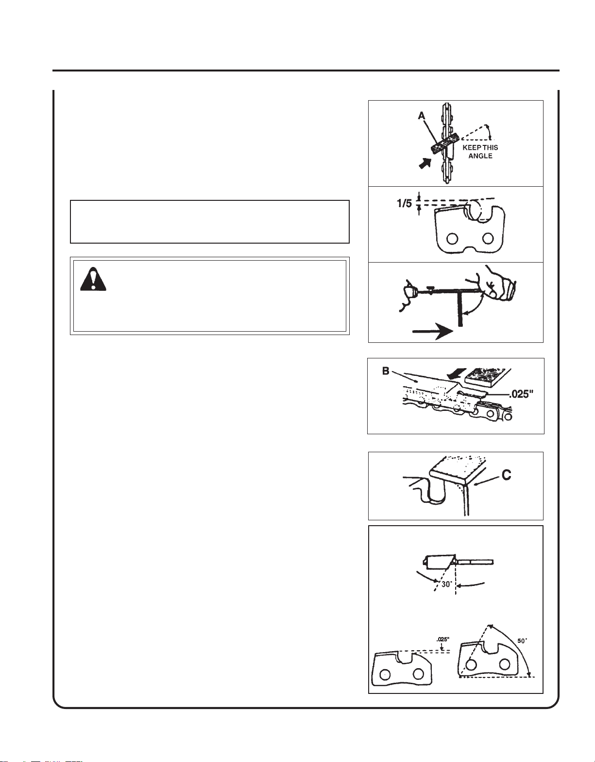
FILING SA W CHAIN
Level 3.
Tools required: 4 mm (5/32 in.) Round File, Flat File, Depth Gauge
IMPORTANT
Dull or damaged cutters will result in poor cutting performance,
increased vibration, and premature saw chain failure.
W ARNING
Always stop engine and disconnect spark plug wire before
servicing guide bar and saw chain. Always wear gloves when filing
saw chain, otherwise serious personal injury may result.
1 . Set round file (A) in cutter at 30° angle. One fifth (1/5) of the file
should be exposed above top cutter edge.
OPERATOR'S MANUAL
30°
1
2
90°
3
27
2 . Keep file horizontal in cutter and file in one direction.
3. File until cutter top and side bevel edges are sharp without nicks.
4 . Place depth gauge tool (B) firmly on top of cutter with .025 in. slot
and end against front cutter raker. File cutter raker with flat file until
flush with top of depth gauge.
5 . Finish cutter sharpening by rounding front raker edge (C) with flat
file.
6 . Properly filed cutter is as shown.
7 . Apply clean oil and rotate saw chain slowly to wash away filings.
8 . If saw chain is coated or clogged with resin, clean in kerosene, then
soak in oil.
4
5
6
(DEPTH GAUGE)
(TOP PLATE ANGLE)
(TOP PLATE CUTTING ANGLE)
Page 28

28
TROUBLESHOOTING
melborPkcehCsutatSesuaCydemeR
TRAHCGNITOOHSELBUORTMELBORPENIGNE
deggolcreniartsleuF
roterubractaleuFroterubractaleufoN
enignE
-sknarc
/drahstrats
t'nseod
trats
,snurenignE
roseidtub
tonseod
etarele
cca
ylreporp
rednilyctaleuF
dnetakrapS
eriwgulpfo
gulptakrapSkrapsoN
retlifriAytridretlifriAraewlamroNecalperronaelC
retlifleuFytridretlifleuF
tnevleuFdeggulptnevleuF
gulPkrapSnrow/ytridgulP
roterubraC
krapsoN
uF
rednilyctaleufoNroterubraCrelaed
leufhtiwtewrelffuMhcirooterutxiMleuF
dgulP
leuf
leuf
amroNecalperrotsujdadnanaelC
tnemtsujdareporpmInoitarbiVtsujdA
deggolcenille
roterubraC
ffohctiwspotS
melborplacirtcelE
hctiwskcolretnI
tcerrocnipagkrapS
nobrachtiwderevoC
leufhtiwdeluoF
evitcefe
seudiser/stnanimatnoCni
niseudiser/stnanimatnoC
raewl
ecalpeR
ecalperronaelC
ecalperronaelC
relaedohcEruoyeeS
ohcEruoyeeS
ekohcnepO
retlifriaecalper/naelC
roterubractsujdA
cEruoyeeS
ohcEruoyeeS
gulpecalpeR
relaedoh
NOothctiwsnruT
relaed
relaedohcEruoyeeS
).ni620.0(mm56.ottsujdA
ecalperronaelC
ecalperronaelC
ecalperronaelC
metsySgnilooC
rotserrAkrapS
neercS
seodenignE
ton
knarc
A/NA/NmelborpenignelanretnIrelaedohcEruoyeeS
/ytrid
metsysgnilooC
deggulp
rotserrakrapS
deggulpneercs
mroNecalpeR
raewla
ninoitarepodednetxE
snoitacolytsud/ytrid
naelC
WARNING
Fuel vapors are extremely flammable and may cause fire and/or explosion. Never test for ignition spark by grounding spark plug near cylinder plug hole, otherwise serious personal injury may result.
Page 29
POWER PRUNER
TM
OPERATOR'S MANUAL
STORAGE
WARNING
During operation the muffler or catalytic muffler and surrounding cover become hot. Always keep exhaust area clear
of flammable debris during transportation or when storing, otherwise serious property damage or personal injury may
result.
Long Term Storage (over 30 days)
Do not store your unit for a prolonged period of time (30 days or longer) without performing protective storage maintenance which includes the following:
1. Store unit in a dry, dust free place, out of the reach of children.
29
WARNING
Do not store in enclosure where fuel fumes may accumulate or reach an open flame or spark or serious personal
injury may result.
2. Place the stop switch in the "OFF" position.
3 . Remove accumulation of grease, oil, dirt and debris
from exterior of unit.
IMPORTANT
Some tree sap and resins are corrosive. Thoroughly
wash the guide bar and sprocket areas after each use,
then coat metal parts with light oil.
4 . Perform all periodic lubrication and services that are
required.
5. Tighten all the screws and nuts.
6. Drain the fuel tank completely and pull the recoil
starter handle several times to remove fuel from the
carburetor.
7 . Remove the spark plug and pour 7 cc (1/4 oz.) of
fresh, clean, two-stroke engine oil into the cylinder
through the spark plug hole.
A. Place a clean cloth over the spark plug hole.
B . Pull the recoil starter handle 2-3 times to
distribute the oil inside the engine.
C. Observe the piston location through the spark
plug hole. Pull the recoil starter handle slowly
until the piston reaches the top of its travel and
leave it there.
8. Install the spark plug (do not connect spark plug
cable).
9. Install the guide bar cover on the guide bar and saw
chain during storage.
Page 30

30
SPECIFICATIONS
MODEL -----------------------------------------------------PPT-260
Length (Standard) -----------------------------------------2.76 m (9 ft. 1 in.)
Length (Extended) ----------------------------------------- 3.90 m (12 ft. 10 in.)
Length w/extension---------------------------------------- 5.44 m (17 ft. 10 in.)
Width--------------------------------------------------------.23 m (9.06 in.)
Height -------------------------------------------------------.22 m (8.7 in.)
Weight (dry) ------------------------------------------------ 7.7 kg (16.9 lb.)
Engine Type ------------------------------------------------ Air cooled, two-stroke, single cylinder gasoline engine
Bore---------------------------------------------------------- 34.0 mm (1.34 in.)
Stroke--------------------------------------------------------28.0 mm (1.10 in.)
Displacement -----------------------------------------------25.4 cc (1.55 cu. in.)
Exhaust System --------------------------------------------Spark Arrestor Muffler w/catalyst
Carburetor --------------------------------------------------Walbro with Purge
Ignition System --------------------------------------------CDI (capacitor discharge ignition)
Spark Plug --------------------------------------------------NGK BPM-8Y Gap 0.65 mm (0.026 in.)
Fuel ----------------------------------------------------------Mixed (Gasoline and Two-stroke Oil)
Fuel/Oil Ratio -----------------------------------------------50:1 two-stroke air cooled engine oil
Gasoline ----------------------------------------------------- 89 Octane unleaded. DO NOT use fuel containing methyl alcohol,
more than 10% ethyl alcohol or 15% MTBE.
Oil------------------------------------------------------------ Power Blend TM Premium Universal 2-Stroke Oil
Fuel Tank Capacity ----------------------------------------0.55 lit. (18.6 US fl. oz.)
Starter System ---------------------------------------------- Automatic Recoil Starter
Clutch -------------------------------------------------------Centrifugal Type
Sprocket Type ---------------------------------------------- 6 tooth spur, 9.53 mm (3/8 in.) pitch
Power Transmission Shaft Assembly ------------------- Aluminum Extrusion
Gear Case Ratio --------------------------------------------1.5:1
Oiling System----------------------------------------------- Automatic
Saw Chain Oil Capacity -----------------------------------225 ml (7.6 oz.)
Handle------------------------------------------------------- Right hand grip w/throttle trigger and lockout
Shoulder Harness ------------------------------------------ Standard
Idle Speed (RPM) ------------------------------------------2,750 - 3,250
Clutch Engagement Speed (RPM) -----------------------3,600 - 4,200
Wide Open Throttle Speed (RPM)----------------------- 9,500 - 11,500
Guide Bar and Saw Chain (91) ---------------------------305 mm (12 in.); 9.53 mm (3/8 in.) pitch, 0.050 gauge
Page 31

POWER PRUNER
TM
NOTES
OPERATOR'S MANUAL
31
Page 32

SERVICING INFORMA TION
PARTS
Genuine ECHO Parts and ECHO REPOWER™ Parts and Assemblies for
your ECHO products are available only from an Authorized ECHO
Dealer. When you do need to buy parts always have the Model
Number, Type and Serial Number of the unit with you. You can find
these numbers on the engine housing. For future reference, write them
in the space provided below.
Model No. _____________ Type _________SN. ______________
/SERIAL NUMBER
SERVICE
Service of this product during the warranty period must be performed
by an Authorized ECHO Service Dealer. For the name and address of
the Authorized ECHO Service Dealer nearest you, ask your retailer or
call: 1-800-432-ECHO (3246). Dealer information is also available on our
Web Site. When presenting your unit for Warranty service/repairs,
proof of purchase is required.
ECHO CONSUMER PRODUCT SUPPORT
If you require assistance or have questions concerning the application,
operation or maintenance of this product you may call the ECHO
Consumer Product Support Department at 1-800-673-1558 from 8:30 am
to 4:30 pm (Central Standard Time) Monday through Friday. Before
calling, please know the model and serial number of your unit to help
your Consumer Product Support Representative.
W ARRANTY REGISTRATION
To ensure trouble free warranty coverage it is important that you
register your ECHO equipment on-line at www.echo-usa.com. Other
registration options are by automated phone at 1-800-432-3246 or by
filling out the warranty registration card supplied with your unit.
Registering your product confirms your warranty coverage and
provides a direct link between you and ECHO if we find it necessary to
contact you.
DEALER?
Call
1-800-432-ECHO
1-800-432-3246
or
www.echo-usa.com
CONSUMER PRODUCT
SUPPORT
1-800-673-1558
8:30 - 4:30 Mon - Fri C.S.T.
ADDITIONAL OR REPLACEMENT MANUALS
Safety Manuals in English/Spanish or English/French are available, free of charge, from your ECHO dealer or at
www.echo-usa.com.
Operator's and Parts Manuals are available by:
• Downloading free from www.echo-usa.com
• Purchasing from your Echo Dealer.
• Manuals are available by sending a written request stating the model number and serial number of your Echo unit, part
number of the manual, your name and address, and mail to the address below.
Safety Videos are available from your Echo dealer. A $5.00 shipping charge will be required for each video.
ECHO, INCORPORATED
400 OAKWOOD ROAD
LAKE ZURICH, IL 60047
www.echo-usa.com
11001001/11999999
12001001/12999999
 Loading...