

Echo GT-201R, SRM-210, GT-200R, SRM-211, SRM-210U Installation And Operating Instructions Manual
...Page 1

- START KIT P/N 99944200001
INSTALLATION/OPERATING INSTRUCTIONS
For Models: GT-200R/201R, SRM-210/211, SRM-210U/211U,
PE-200/201, SHC-210/211, PPF-210/211
If you are unsure or are not equipped with the necessary tools, you may want to take your unit to an Echo
Service Dealer for installation of this kit. To help you decide whether you want to DO-IT-YOURSELF or have an
Echo dealer install this kit, we have rated this procedure as a SKILL LEVEL 2, which means some mechanical
experience and basic knowledge in the use of hand tools is necessary.
The Echo I-Start system is a starter accessory that will make your Echo unit easier to start by reducing the
pulling force by 75%.
If after reading these instructions, you are not sure of your ability to safely complete the installation, Echo
recommends you return the unit to your Echo dealer for service.
NOTE:
Carefully follow all assembly instructions,
nents.
Tools Needed: 13mm Socket and Ratchet, Spark Plug Wrench, Cross Head Screwdriver, 3mm Hex Wrench,
Pliers, 3 X 1/4 in. Plastic Dowel Piston Stop similar to tooth brush handle (Recommended
Echo Piston Stop Part Number 91017).
in sequence, in order to avoid damage to the I-Start compo-
Contents: i - Start Assembly, Two Pawl Catcher, Starter Spacer, 3-Tapping Screws, Engine Stand, Eye
Plate, Instruction Sheet
INSTALLATION
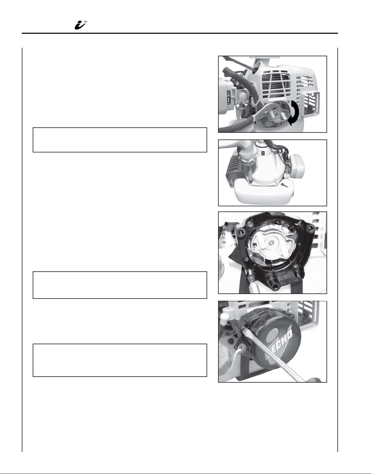
DISASSEMBLY:
1. Move stop switch to stop position.
2. Disconnect spark plug lead and remove spark plug with
spark plug wrench.
3. Remove four (4) starter screws with 3mm hex wrench,
turning counter clockwise (CCW). Retain screws for
reassembly.
NOTE:
Starter screws have thread lock compound and may be
difficult to remove. To prevent damaging screws, turn screws
½ turn CCW then ¼ turn clockwise (CW). Repeat procedure
until screws are removed.
4. Lift starter assembly from engine.
5. Insert piston stop into spark plug hole. Rotate pawl catcher
CCW until piston rests firmly against piston stop preventing
crankshaft from further rotation.
6. Use 13mm socket to remove pawl catcher from crankshaft,
turning CCW.
X7712271301
X771000111
05/06
Page 2
2
ASSEMBLY:
1. Thread new pawl catcher CW onto crankshaft end. Turn
pawl catcher and crankshaft CW until the piston rests
firmly against piston stop, preventing crankshaft from further
rotation.
2. Use pliers to clamp pawl catcher, then turn CW until tight.
NOTE:
Do not use excessive force when clamping pawl catcher to
avoid damage to assembly.
3. Remove two bottom fan cover screws and retain.
4. Install engine stand to fan cover with two fan cover screws.
Tighten securely.
- START INSTALLATION/OPERATING INSTRUCTIONS
5. Position spacer with triangular tab to the left when viewed
from the rear. Install eye plate between spacer and engine
stand flange. Align screw holes and secure spacer, engine
stand and eye plate using four (4) screws removed from
original starter assembly.
6. Install the i-Start assembly to the spacer with starter
handle positioned to the left when viewed from the rear.
Secure with three (3) tapping screws supplied.
NOTE:
When installing starter assembly to spacer, pull starter rope
six (6) inches until starter assembly fits flush with spacer.
7. Remove piston stop. Slowly pull starter rope to verify engine
rotates freely. If engine does not rotate freely, check spacer
and starter alignment.
8. Install spark plug and connect spark plug lead.
NOTE:
When the starter is correctly installed, you will hear a
clicking sound when the starter rope is pulled out then
returned.
Page 3

ST ARTING:
- START INST ALLATION/OPERATING INSTRUCTIONS
3
COLD STARTING
1. Move stop switch button (A) away from stop position.
2. Move choke lever (B) to cold start (closed) position.
3. Pump primer bulb (C) until fuel is visible and flows freely in
the clear fuel tank return line. Pump bulb an additional 4 or
5 times.
NOTE:
Energy is stored in the starter spring each time the handle/
rope is pulled. Generally two to six pulls, using light pulling
forces, will store enough energy to engage the starter and
spin the engine. Do not pull the rope out to end stop.
4. Lay the unit on a flat, clear area. Firmly grasp right hand
grip and throttle trigger lockout with left hand, and fully
depress throttle trigger to wide open position. Gently pull
starter handle/rope (D) until engine fires or 2 to 3 engine
engagements.
5. After engine fires or 2 to 3 engine engagements, move
choke lever to “run” (open) position.
6. Pull starter handle/rope (D) until engines starts and runs.
7. Allow engine to warm up at idle for several minutes.
NOTE:
If engine does not start with choke in “run” (open) position
after 5 engine engagements, repeat instructions.
GT
A
A
B
C
SRM
8. After engine warm up, gradually depress throttle trigger to
increase engine RPM.
WARM STARTING
The starting procedure is the same as Cold Start except DO NOT
close the choke, and do not depress throttle trigger to wide open
position.
1. Move stop switch button (A) away from the STOP position.
2. Lay the unit on a flat, clear area and gently pull the recoil
starter handle (D) until engine fires.
NOTE:
If engine does not start after 5 engine engagements, use
Cold Start Procedure.
D
D
Page 4

ECHO CONSUMER PRODUCT SUPPORT
If you require assistance or have questions concerning the application, operation or maintenance of this product
you may call the ECHO Consumer Product Support Department at 1-800-673-1558 from 8:30 am to 4:30 pm
(Central Standard Time) Monday through Friday. Before calling, please know the model and serial number of
your unit to help your Consumer Product Support Representative.
ECHO, INCORPORATED
400 Oakwood Road
Lake Zurich, IL 60047
www.echo-usa.com
Page 5

JUEGO I - START N/P 99944200001
INSTRUCCIONES DE INSTALACIÓN/OPERACIÓN
PARA LOS MODELOS: GT-200R/201R, SRM-210/211, SRM-210U/211U,
PE-200/201, SHC-210/211, PPF-210/211
Si no está seguro o no está equipado con las herramientas necesarias, puede llevar su unidad a un distribuidor
de servicio ECHO para la instalación de este juego. Para ayudarle a decidir si quiere instalar este juego USTED
MISMO o con la ayuda de un distribuidor de Echo, hemos clasificado este procedimiento como un nivel de
habilidad 2, que significa que es necesaria cierta experiencia mecánica y un conocimiento básico del uso de
herramientas manuales.
El sistema I-Start de Echo es un accesorio de arranque que hará más fácil arrancar su unidad Echo al reducir la
fuerza de tracción en un 75%.
Si después de leer estas instrucciones no está seguro de su habilidad para completar bien la instalación, Echo
recomienda que lleve la unidad a su distribuidor Echo para su servicio.
NOTA:
Siga con cuidado todas las instrucciones de montaje, en orden, para evitar daños en los componentes del
I-Start.
Herramientas necesarias: Sistema de adaptador y trinquete de 13 mm, llave para bujías, destornillador en
cruz, llave hexagonal de 3 mm, alicates, tope de pistón de espiga de plástico de 3
X 1/4 pulg similar al mango de un cepillo de dientes (Se recomienda el tope de
pistón de Echo número de pieza 91017).
Contenido: Conjunto de i - Start, traba de dos fiadores, espaciador del motor de arranque, 3
tornillos roscadores, soporte del motor, placa del ojo, hoja de instrucciones
INSTALACIÓN
DESMONTAJE:
1. Mueva el interruptor de parada a la posición de parada.
2. Desconecte el cable principal de la bujía y quite la bujía
con la llave apropiada.
3. Quite los cuatro (4) tornillos del motor de arranque con la
llave hexagonal de 3 mm, girándolos hacia la izquierda.
Conserve los tornillos para el montaje.
NOTA:
Los tornillos del motor de arranque tienen compuesto
trabarroscas y tal vez sea difícil quitarlos. Para no dañar los
tornillos, gire el tornillo 1/2 vuelta a la izquierda y después
1/4 de vuelta a la derecha. Repita el procedimiento hasta
quitar los tornillos.
4. Levante el conjunto del motor de arranque del motor.
5. Introduzca el tope del pistón en el agujero de la bujía. Gire
la traba de dos fiadores hacia la izquierda hasta que el
pistón descanse firmemente contra el tope del pistón,
impidiendo una rotación adicional del cigüeñal.
6. Use el sistema de adaptador y trinquete de 13 mm para
quitar la traba de fiadores del cigüeñal, girándola hacia la
izquierda.
X7712271301
X771000111
05/06
Page 6

JUEGO I - START INSTRUCCIONES DE INSTALACIÓN/OPERACIÓN
MONT AJE:
1. Enrosque la nueva traba de fiadores hacia la derecha en el
extremo del cigüeñal. Gire la traba de fiadores y el cigüeñal
hacia la derecha hasta que el pistón se asiente firmemente
contra el tope del pistón, impidiendo una rotación adicional
del cigüeñal.
2. Use unos alicates para sujetar la traba de fiadores, y
después gire hacia la derecha hasta que esté bien apretada.
NOTA:
No use una fuerza excesiva al sujetar la traba de fiadores
para evitar que se dañe el conjunto.
3. Quite los dos tornillos inferiores de la tapa del ventilador y
consérvelos.
4. Instale el soporte del motor en la tapa del ventilador con los
dos tornillos de la misma. Apriete bien.
2
5. Coloque el espaciador con la lengüeta triangular hacia la
izquierda cuando se ve desde detrás. Instale la placa del
ojo entre el espaciador y el reborde del soporte del motor.
Alinee los agujeros de los tornillos y sujete el espaciador,
el soporte del motor y la placa del ojo usando cuatro los (4)
tornillos quitados del conjunto del motor de arranque
original.
6. Instale el conjunto i-Start en el espaciador con el asa del
motor de arranque colocada hacia la izquierda cuando se
ve por detrás. Sujételos con los tres (3) tornillos roscadores
proporcionados.
NOTA:
Al instalar el conjunto del motor de arranque en el
espaciador, tire de la cuerda del motor de arranque unas
seis (6) pulgadas hasta que el conjunto del motor de
arranque esté al mismo nivel que el espaciador.
7. Quite el tope del pistón. Tire lentamente de la cuerda del
motor de arranque para verificar que el motor gire libremente. Si no gira libremente el motor, compruebe el alineamiento del espaciador y motor de arranque.
8. Instale la bujía y conecte el cable de la bujía.
NOTA:
Cuando el motor de arranque esté bien instalado, oirá un clic
cuando se tire de la cuerda del motor de arranque y se
suelte.
Page 7

3
ARRANQUE:
JUEGO I - START INSTRUCCIONES DE INSTALACIÓN/OPERACIÓN
ARRANQUE EN FRÍO
1. Aleje el interruptor de parada (A) de la posición de parada.
2. Mueva la palanca del estrangulador (B) a la posición de
arranque en frío (cerrada).
3. Pulse el cebador (C) hasta que el combustible se haga
visible y pase libremente por el tubo de retorno transparente del tanque de combustible. Pulse el cebador 4 ó 5 veces
más.
NOTA:
Se almacena energía en el resorte del motor de arranque
cada vez que se tira de la palanca/cuerda. Normalmente al
efectuar de dos a seis tirones, usando fuerzas de tracción
ligeras, se almacenará suficiente energía para conectar el
motor de arranque y hacer girar el motor. No tire de la
cuerda hasta el tope del extremo.
4. Ponga la unidad en un área plana y despejada. Agarre
fuertemente la empuñadura derecha y la traba del gatillo
del acelerador con la mano izquierda y después apriete el
gatillo hasta la posición completamente abierta. Tire
ligeramente de la palanca/cuerda del motor de arranque (D)
hasta que arranque el motor o hasta que se produzcan 2 a
3 conexiones del motor.
5. Después de arrancar el motor o de 2 ó 3 conexiones del
motor, mueva la palanca del estrangulador a la posición de
“marcha” (abierta).
6. Tire de la palanca/cuerda del motor de arranque (D) hasta
que el motor arranque y funcione.
7. Deje calentarse el motor en marcha en vacío durante varios
minutos.
GT
A
A
B
C
SRM
NOTA:
Si el motor no arranca con el estrangulador en la posición
de “marcha” (abierto) después de 5 conexiones del motor,
repita las instrucciones.
8. Después de que se caliente el motor, apriete gradualmente
el gatillo del acelerador para aumentar las rpm del motor.
ARRANQUE EN CALIENTE
Este procedimiento de arranque es igual que el de arranque en frío
excepto que NO se debe cerrar el estrangulador y no se debe
pulsar el gatillo del acelerador a la posición completamente
abierta.
1. Aleje el botón del interruptor de parada (A) de la posición
de PARADA.
2. Ponga la unidad sobre un área plana despejada y tire
suavemente del tirador del motor de arranque de retroceso
(D) hasta que se encienda el motor.
NOTA:
Si el motor no arranca después de 5 conexiones, use el
Procedimiento de arranque en frío.
D
D
Page 8

ASISTENCIA PARA PRODUCTOS DEL CONSUMIDOR DE ECHO
Si necesita asistencia o tiene dudas referentes a la aplicación, operación o mantenimiento de este producto
puede llamar al Departamento de asistencia de productos del consumidor de ECHO, 1-800-673-1558 de 8:30
de la mañana a 4:30 de la tarde (hora central estándar) de lunes a viernes. Antes de llamar, tenga a mano el
número de modelo y serie de su unidad para ayudar a su representante de asistencia de productos del
consumidor.
ECHO, INCORPORATED
400 Oakwood Road
Lake Zurich, IL 60047
www.echo-usa.com
Page 9

KIT I - START RÉF. 99944200001
I
NSTRUCTIONS D’INSTALLATION ET D’UTILISATION
Pour modèles : GT-200R/201R, SRM-210/211, SRM-210U/211U,
PE-200/201, SHC-210/211, PPF-210/211
En cas de doute ou en l’absence de l’outillage nécessaire, la machine peut être confiée à un concessionnaire
ECHO pour l’installation du kit. Pour aider l’utilisateur à décider s’il préfère INSTALLER LUI-MÊME le kit ou
confier l’installation à un concessionnaire Echo, nous attribué un NIVEAU DE DIFFICULTÉ 2, ce qui signifie
qu’une certaine expérience mécanique et une connaissance élémentaire de l’utilisation d’outils à main est
nécessaire.
Le système Echo I-Start est un accessoire de démarrage qui facilite le lancement du moteur en réduisant la
force de traction du cordon lanceur de 75 %.
Si, après lecture de ces instructions, l’utilisateur n’est pas certain de pouvoir installer le kit en toute sécurité,
nous lui recommandons de confier l’installation à un concessionnaire ECHO.
REMARQUE :
Suivre attentivement les instructions d’assemblage,
composants du système I-Start.
Outils nécessaires : Manche à cliquet avec douille de 13 mm, clé à bougie, tournevis cruciforme, clé hexago-
nale de 3 mm, pinces, outils de blocage de piston de 75 x 6 mm, similaire à un manche
de brosse à dents (la pièce Echo 91017 est recommandée).
dans l’ordre, afin de ne pas risquer d’endommager les
Contenu : Lanceur I-Start, cliquet à deux griffes, pièce d’écartement, 3 vis taraudeuses, support
moteur, plat d’oeil, feuille d’instructions.
INST ALLATION
DÉMONTAGE :
1. Mettre le commutateur d’arrêt en position stop.
2. Débrancher le fil de bougie et retirer la bougie à l’aide de la
clé à bougie.
3. Retirer les quatre (4) vis de fixation du lanceur en les
tournant vers la droite. Conserver les vis en vue du remontage.
REMARQUE :
Les vis du lanceur sont enduites d’un frein filet et peuvent
être difficiles à retirer. Pour éviter de les endommager, les
tourner de 1/2 de tour vers la gauche, puis de 1/4 de tour
vers la droite. Répéter cette procédure jusqu’à ce que les vis
puissent être retirées.
4. Retirer le lanceur du moteur.
5. Observer la position du piston au travers du trou de la
bougie. Tourner le cliquet vers la gauche jusqu’à ce que le
piston s’appuie fermement contre sa butée, empêchant le
vilebrequin de tourner.
6. Retirer l’écrou de fixation du cliquet au moyen d’une clé à
douille de 13 mm, en tournant vers la gauche.
X7712271301
X771000111
05/06
Page 10

KIT I - START INSTRUCTIONS D’INSTALLATION ET D’UTILISATION2
ASSEMBLAGE :
1. Visser le nouveau cliquer sur l’extrémité du vilebrequin, en
tournant vers la droite. Tourner le cliquet et le vilebrequin
vers la droite jusqu’à ce que le piston s’appuie fermement
contre sa butée, empêchant le vilebrequin de tourner.
2. Bloquer le cliquet avec une pince, puis le serrer en tournant
vers la droite.
REMARQUE :
Pour éviter d’endommager le cliquet, ne pas trop forcer.
3. Retirer les deux vis de fixation inférieure du couvercle de
ventilateur et les conserver.
4. Fixer le support moteur sur le couvercle de ventilateur au
moyen de deux vis. Serrer fermement.
5. Placer la pièce d’écartement avec la patte triangulaire vers
la gauche (lorsque vue de l’arrière). Installer plat d’oeil entre
la pièce d’écartement et la bride du support moteur.
Aligner les trous de vis et assujettir la pièce d’écartement,
la bride du support moteur, et la plat d’oeil sur le moteur au
moyen des quatre (4) vis retirées du lanceur original.
6. Installer le système I-Start sur la pièce d’écartement la
poignée du cordon à gauche (lorsque vue de l’arrière). Fixer
avec trois (3) vis taraudeuses fournies.
REMARQUE :
Lors de l’installation du lanceur sur la pièce d’écartement,
tirer le cordon de 15 cm de manière à ce que le lanceur
repose à plat sur la pièce d’écartement.
7. Retirer la butée du piston. Tirer lentement le cordon du
lanceur pour s’assurer que le moteur tourne librement. Si
ce n’est pas le cas, vérifier l’alignement de la pièce d’écartement et du lanceur.
8. Installer la bougie et brancher le fil de bougie.
REMARQUE :
Si le lanceur est correctement installé, il produit un déclic
lorsque le cordon est tiré, puis rétracté.
Page 11

KIT I - START INSTRUCTIONS D’INSTALLATION ET D’UTILISATION 3
DÉMARRAGE :
DÉMARRAGE À FROID
1. Retirer le commutateur (A) de la position stop.
2. Mettre le levier de levier de volet de départ (B) en position
de démarrage à froid (fermé).
3. Pomper la poire d’amorçage (C) jusqu’à ce que le carburant
soit visible dans la conduite de retour transparente. Pomper
4 ou 5 fois de plus.
REMARQUE :
Le ressort du lanceur emmagasine de l’énergie chaque fois
que le cordon est tiré. En général deux à six tractions, sans
forcer permettent d’emmagasiner assez d’énergie pour
engager le lanceur et faire tourner le moteur. Ne pas tirer le
cordon à fond de course.
4. Poser l’outil sur une surface plane et dégagée. Saisir
fermement la poignée de droite et engager le verrouillage de
gâchette et enfoncer complètement la gâchette en position
pleins gaz, avec la main gauche. Tirer sur le cordon lanceur
(D), sans forcer, jusqu’à ce que le moteur démarre (ou un
maximum de 2 ou 3 fois).
5. Une fois le moteur lancé (ou après 2 à 3 tractions du
lanceur), mettre le levier de volet de départ sur la position
de marche (ouvert).
6. Tirer sur le cordon lanceur (D) jusqu’à ce que le moteur
démarre et reste en marche.
7. Laissez le moteur se réchauffer au ralenti pendant plusieurs
minutes.
GT
A
A
B
C
SRM
REMARQUE :
Si le moteur ne démarre pas avec le starter en position
« run » (ouvert) après avoir tiré 5 fois sur le cordon lanceur,
reprendre les instructions au début.
8. Une fois le moteur réchauffé, appuyer progressivement sur
la gâchette des gaz pour augmenter le régime jusqu’à la
vitesse de fonctionnement.
DÉMARRAGE D’UN MOTEUR CHAUD
Procéder de la même façon que pour le démarrage à froid, mais
NE PAS fermer le volet de départ et ne pas appuyer à fond sur la
gâchette des gaz.
1. Retirer le commutateur (A) de la position STOP.
2. Poser l’outil sur une surface plane et dégagée et tirer sur la
poignée du cordon lanceur (D) jusqu’à ce que le moteur
démarre.
REMARQUE :
Si le moteur ne démarre pas après 5 tractions du cordon,
utiliser la procédure de démarrage à froid.
D
D
Page 12

SERVICE APRÈS-VENTE ECHO
Pour toute assistance ou question concernant l’application, l’utilisation ou l’entretien de ce produit, appeler le
service d’assistance clients ECHO au 1-800-673-1558, de 8 heures 30 à 16 heures 30 trente (heure normale du
centre), du lundi au vendredi. Avant d’appeler, veiller à disposer des numéros de modèle et de série de l’unité
afin d’aider votre représentant du service après-vente.
ECHO, INCORPORATED
400 Oakwood Road
Lake Zurich, IL 60047
www.echo-usa.com
 Loading...