

Page 1

DEBRIS LOADER
DL8390 - 8 INCH 390cc HONDA
DL10570 - 10 INCH 570cc BRIGGS
DL12670 (75124) - 12 INCH 670cc HONDA
DL12725 - 12 INCH 725cc KOHLER
Rev. 111407
Manual P/N 13991-00
Companion to P/N 13992-00
SN/VIN Range: 706715-904778
5VJAA01X7W000237-5VJAA00139W001899
OWNER'S MANUAL
Page 2

Before You Begin
DEAR ECHO BEAR CAT CUSTOMER
Thank you for purchasing a ECHO Bear Cat product. The ECHO Bear Cat line is designed, tested, and manufactured
to give years of dependable performance. To keep your machine operating at peak efciency, it is necessary to adjust
it correctly and make regular inspections. The following pages will assist you in the operation and maintenance of
your machine. Please read and understand this manual before operating your machine.
If you have any questions or comments about this manual, please call us toll-free at 1-800-247-7335.
If you have any questions or problems with your machine, please call or write your local authorized ECHO Bear Cat Dealer.
This document is based on information available at the time of its publication. ECHO Bear Cat is continually
making improvements and developing new equipment. In doing so, we reserve the right to make changes or add
improvements to our product without obligation for equipment previously sold.
PLEASE SEND US YOUR WARRANTY CARD
A warranty card is included in your owner's kit packaged with your machine. Please take the time to ll in the
information requested on the card. When you send your completed card to us, we will register your machine and start
your coverage under our limited warranty.
FOR MACHINE SERVICE OR PARTS:
For service assistance, contact your nearest authorized
ECHO Bear Cat dealer or the factory. For parts, contact
your authorized dealer. Your dealer will need to know
the serial number of your machine to provide the most
efcient service. See below for information on how to
identify and record the serial number for your machine.
FOR ENGINE SERVICE OR PARTS:
For engine service or parts, contact your nearest
authorized engine dealer. ECHO Bear Cat does not
handle any parts, repairs or warranties for engines.
SERIAL NUMBER LOCATION
Please record the serial number in the space provided
and on the warranty and registration card.
MANUFACTURED BY CRARY INDUSTRIES
WEST FARGO, NORTH DAKOTA 58078 U.S.A.
SERIAL NUMBER
MANUFACTURED IN U.S.A.
XXXXXX
ORDERING PARTS
Only genuine ECHO Bear Cat replacement parts should
be used to repair the machine. Replacement parts
manufactured by others could present safety hazards,
even though they may t on this machine. Replacement
parts are available from your ECHO Bear Cat dealer.
Provide the following when ordering parts:
The SERIAL NUMBER of your machine.
The PART NUMBER of the part.
The PART DESCRIPTION.
The QUANTITY needed.
SERIAL NUMBER
HOW TO CONTACT ECHO BEAR CAT
ADDRESS PHONE E-MAIL HOURS
237 NW 12th Street
P.O. Box 849
West Fargo, ND 58078
*Original Instructions
© 2006, CRARY INDUSTRIES, ALL RIGHTS RESERVED. PRODUCED AND PRINTED IN THE U.S.A.
800-247-7335
opesales@crary.com
701-282-5520
service@crary.com
FAX: 701-282-9522
Monday - Friday,
8 am to 5 pm
Central Time
Page 3

LIMITED WARRANTY
This warranty applies to all AG and Outdoor Power Equipment manufactured by Crary Industries.
Crary Industries warrants to the original owner each new Crary Industries product to be free from defects
in material and workmanship, under normal use and service. The warranty shall extend 1 year from date of
delivery for income producing (commercial) applications and 2 years from date of delivery for non-income
producing (consumer) use of the product. The product is warranted to the original owner as evidenced by a
completed warranty registration on file at Crary Industries. Replacement parts are warranted for (90) days
from date of installation.
THE WARRANTY REGISTRATION MUST BE COMPLETED AND RETURNED TO CRARY INDUSTRIES
WITHIN 10 DAYS OF DELIVERY OF THE PRODUCT TO THE ORIGINAL OWNER OR THE WARRANTY
WILL BE VOID.
In the event of a failure, return the product, at your cost, along with proof of purchase to the selling Crary
Industries dealer. Crary Industries will, at its option, repair or replace any parts found to be defective in material
or workmanship. Warranty on any repairs will not extend beyond the product warranty. Repair or attempted
repair by anyone other than a Crary Industries dealer as well as subsequent failure or damage that may occur
as a result of that work will not be paid under this warranty. Crary Industries does not warrant replacement
components not manufactured or sold by Crary Industries.
1. This warranty applies only to parts or components that are defective in material or workmanship.
2. This warranty does not cover normal wear items including but not limited to bearings, belts, pulleys, lters
and chipper knives.
3. This warranty does not cover normal maintenance, service or adjustments.
4. This warranty does not cover depreciation or damage due to misuse, negligence, accident or improper
maintenance.
5. This warranty does not cover damage due to improper setup, installation or adjustment.
6. This warranty does not cover damage due to unauthorized modications of the product.
7. Engines are warranted by the respective engine manufacturer and are not covered by this warranty.
Crary Industries is not liable for any property damage, personal injury or death resulting from the unauthorized
modification or alteration of a Crary product or from the owner’s failure to assemble, install, maintain or operate
the product in accordance with the provisions of the Owner’s manual.
Crary Industries is not liable for indirect, incidental or consequential damages or injuries including but not
limited to loss of crops, loss of profits, rental of substitute equipment or other commercial loss.
This warranty gives you specific legal rights. You may have other rights that may vary from area to area.
Crary Industries makes no warranties, representations or promises, expressed or implied as to the performance
of its products other than those set forth in this warranty. Neither the dealer nor any other person has any
authority to make any representations, warranties or promises on behalf of Crary Industries or to modify the
terms or limitations of this warranty in any way. Crary Industries, at its discretion, may periodically offer limited,
written enhancements to this warranty.
CRARY INDUSTRIES RESERVES THE RIGHT TO CHANGE THE DESIGN AND/OR SPECIFICATIONS
OF ITS PRODUCTS AT ANY TIME WITHOUT OBLIGATION TO PREVIOUS PURCHASERS OF ITS
PRODUCTS.
Page 4

TABLE OF CONTENTS
DESCRIPTION PAGE
SAFETY ....................................................................................................................... 1
1.1 SAFETY ALERT SYMBOL ........................................................................................1
1.2 EMMISSION INFORMATION .................................................................................... 1
1.3 BEFORE OPERATING.............................................................................................. 2
1.4 OPERATION SAFETY .............................................................................................. 2
1.5 BATTERY SAFETY ...................................................................................................3
1.6 MAINTENANCE/STORAGE SAFETY .......................................................................3
1.7 TOWING SAFETY .....................................................................................................3
1.8 SAFETY DECALS ......................................................................................................4
1.9 SAFETY DECAL LOCATIONS ................................................................................... 5
1.9 SAFETY DECAL LOCATIONS ................................................................................... 6
ASSEMBLY ................................................................................................................ 7
2.1 ATTACH THE WHEELS (12" MODELS) .................................................................... 7
2.2 ATTACH THE HITCH (12" MODELS) ......................................................................... 7
2.3 ATTACH THE VACUUM HOSE ..................................................................................8
2.4 ATTACH BLOWER DISCHARGE ............................................................................... 9
2.5 DISCHARGE SUPPORT (725cc MODELS) ..............................................................9
2.6 DISCHARGE TRANSITION (725cc MODELS) ..........................................................9
2.7 CONNECT THE BATTERY (12" MODELS) ...............................................................9
FEATURES & CONTROLS ....................................................................................... 10
3.1 DL12670 (75124) CONTROLS ................................................................................10
3.2 DL12725 CONTROLS .............................................................................................. 11
3.3 HITCH MOUNT CONTROLS ................................................................................... 11
3.4 ENGINE CONTROLS ..............................................................................................12
OPERATION ............................................................................................................ 13
4.1 ATTACHING/UNHOOKING DEBRIS LOADER ........................................................ 13
4.2 STARTING THE MACHINE ...................................................................................... 13
4.2 STARTING THE MACHINE ...................................................................................... 14
4.3 STOPPING THE MACHINE .....................................................................................14
4.4 VACUUMING OPERATION ......................................................................................14
4.5 VACUUMING TIPS AND SAFETY ...........................................................................14
4.6 TRANSPORTING ..................................................................................................... 14
SERVICE & MAINTENANCE .................................................................................. 15
5.1 SERVICE AND MAINTENANCE SCHEDULE ......................................................... 15
5.2 REFUELING INFORMATION ................................................................................... 15
5.2 REFUELING INFORMATION ................................................................................... 16
5.3 ENGINE OIL .............................................................................................................16
5.4 ADJUSTING DRIVE BELT (670cc MODEL) ............................................................. 16
5.4 ADJUSTING DRIVE BELT (670cc MODEL) ............................................................. 17
5.5 REPLACING DRIVE BELT (670cc MODEL) ............................................................ 17
5.5 REPLACING DRIVE BELT (670cc MODEL) ............................................................ 18
5.6 REPLACING THE FLEX HOSE ...............................................................................18
5.7 REPLACING WEAR LINERS ................................................................................... 18
5.8 TRAILER SERVICE .................................................................................................19
5.9 GREASABLE BEARINGS (670cc MODEL) ............................................................. 19
5.10 UNPLUGGING THE ROTOR .................................................................................19
5.10 UNPLUGGING THE ROTOR .................................................................................20
5.11 UNPLUGGING THE INLET HOSE ......................................................................... 20
TROUBLESHOOTING ............................................................................................ 21
SPECIFICATIONS ................................................................................................... 22
7.1 DEBRIS LOADER SPECIFICATIONS ..................................................................... 22
7.2 BOLT TORQUE ........................................................................................................ 23
Page 5

1
Section
SAFETY
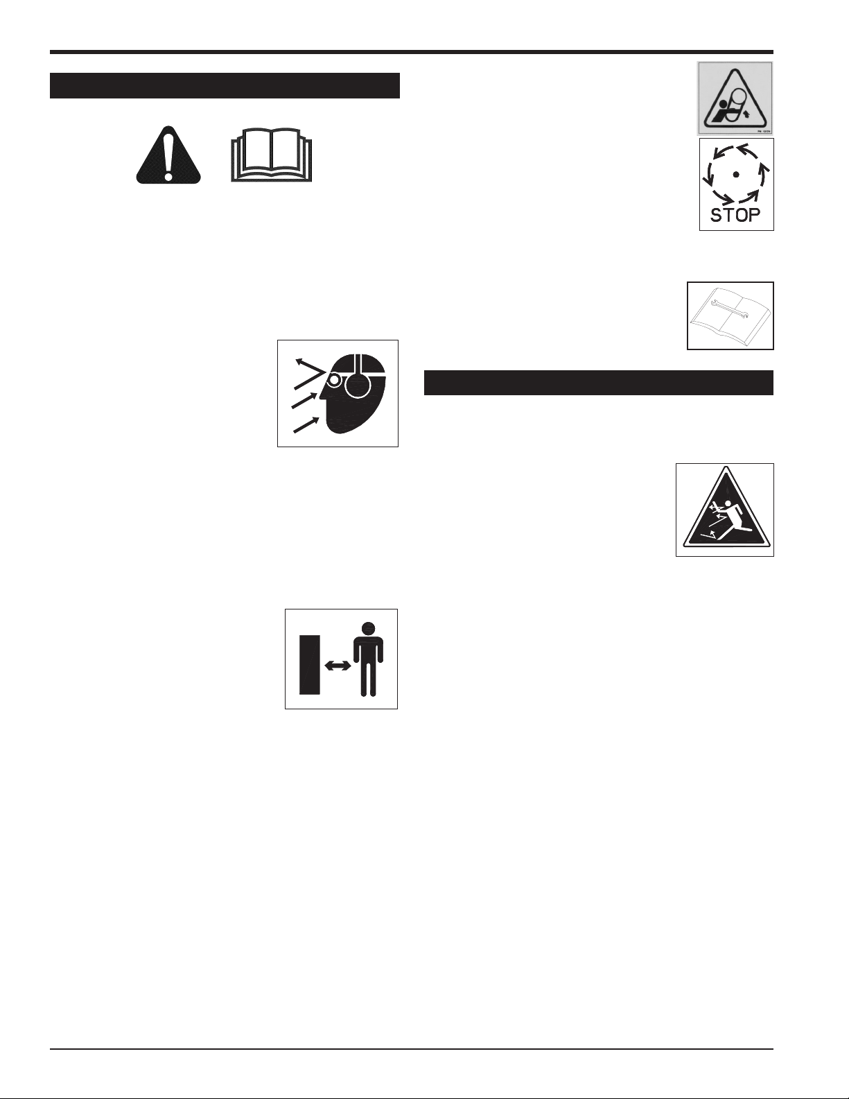
1.1 SAFETY ALERT SYMBOL
This is the safety alert symbol. It is used in this Owner /
Operator's Manual and on your machine to alert you to
potential hazards.
Whenever you see this symbol, read and obey the safety
message that follows it. Failure to obey the safety message
could result in personal injury, death or property damage.
CAUTION
Indicates a potentially hazardous situation that, if not
avoided, may result in minor or moderate injury.
WARNING
Indicates a potentially hazardous situation that, if not
avoided, could result in death or serious injury.
DANGER
1.2 EMMISSION INFORMATION
WARNING TO OWNERS IN CALIFORNIA AND
OTHER STATES OPERATING OUTDOOR POWER
EQUIPMENT
Under California Law
and under the laws of
several other states
you are not permitted
to operate an internal
combustion engine
using hydrocarbon fuels
on any forest covered,
brush covered or grass
covered land or on land
covered with grain hay or other flammable agricultural crop,
without an engine spark arrester in continuous effective
working order.
The engine on your power equipment, like most outdoor
power equipment, is an internal combustion engine that
burns gasoline, a hydrocarbon fuel. Therefore, your power
equipment must be equipped with a spark arrester muffler
in continuous effective working order. The spark arrester
must be attached to the engine exhaust system in such a
manner that flames or heat from the system will not ignite
flammable material.
Failure of the owner/operator of the equipment to comply
with this regulation is a misdemeanor under California law,
and may also be a violation of other state and or federal
regulations, laws, ordinances, or codes. Contact your local
fire marshal or forest service for specific information about
what regulations apply in your area.
Indicates an imminently hazardous situation that, if
not avoided, will result in death or serious injury.
Debris Loader Owner’s Manual
The standard mufflers on the 390cc Honda engines and
725cc Kohler engines are equipped with a spark arrester.
The standard mufflers installed on 670cc Honda engines
and 570 Briggs & Stratton engines are not equipped with a
spark arrester. One must be added before use if the 670cc
and 570cc machines are intended to be used in an area
where a spark arrester is required by law. Contact the local
authorities if these laws apply to you. See your authorized
engine dealer for spark arrester options.
1
Page 6
SAFETY
1.3 BEFORE OPERATING
1. Read and understand this Owner/Operators manual.
Be completely familiar with the controls and the proper
use of this equipment.
2. Familiarize yourself with all of the safety and operating
decals on this equipment and on any of its attachments
or accessories.
3. Keep safety decals clean and legible. Replace missing
or illegible safety decals.
4. Obtain and wear safety glasses
and use hearing protection at
all times when operating this
machine.
5. Avoid wearing loose tted cloth-
ing. Never operate this machine while wearing clothing
with drawstrings that could wrap around or get caught
in the machine.
6. Do not operate this machine if you are under the
inuence of alcohol, medications, or substances that
can affect your vision, balance or judgement. Do not
operate if tired or ill. You must be in good health to
operate this machine safely.
7. Do not operate this equipment in
the vicinity of bystanders. Keep
the area of operation clear of
all persons, particularly small
children. It is recommended that
bystanders keep at least 50 feet
(15 meters) away from the area
of operation.
8. Do not allow children to operate this equipment.
9. Use only in daylight or good articial light.
10. Do not run this equipment in an enclosed area. Engine
exhaust contains carbon monoxide gas, a deadly poison that is odorless, colorless and tasteless. Do not
operate this equipment in or near buildings, windows
or air conditioners.
11. Always use an approved fuel container. Do not remove
gas cap or add fuel when engine is running. Add fuel
to a cool engine only.
12. Do not ll fuel tank indoors. Keep open ames, sparks,
smoking materials and other sources of combustion
away from fuel.
13. Do not operate machine without shields in place. Fail-
ure to do so may cause serious injury or death.
14. Keep all guards, deectors, and shields
in good working condition.
15. Before inspecting or servicing any part
of this machine, shut off power source,
disconnect spark plug wire from spark
plug and make sure all moving parts
have come to a complete stop.
16. Check that all screws, nuts, bolts, and
other fasteners are secured, tightened and in proper
working condition before starting the machine and once
every 8 hours of operation.
17. Do not transport or move machine
while the machine is operating or
running.
1.4 OPERATION SAFETY
1. Always stand clear of discharge area when operating
this machine. Keep face and body away from feed and
discharge openings.
2. Keep hands and feet out of feed and
discharge openings while machine is
operating to avoid serious personal
injury. Stop and allow machine to
come to a complete stop before clearing obstructions.
3. Set up your work site so you are not endangering trafc
and the public. Take great care to provide adequate
warnings.
4. Do not climb on machine when operating. Keep proper
balance and footing at all times.
5. Check inlet to verify it is empty before starting the
machine.
6. The rotor will continue to rotate when belt is disengaged.
7. When vacuuming material into machine, do not allow
metal, rocks, bottles, cans or any other foreign material
to be fed into the machine.
8. Ensure debris does not blow into trafc, parked cars,
or pedestrians.
9. Check blade bolts for proper torque after every 8 hours
of operation.
10. Shut off machine immediately if it vacuums up any
foreign object or the machine starts making an unusual noise or vibrating. Allow the machine to stop
completely. After machine stops:
A. Remove spark plug wire.
B. Inspect for damage.
C. Replace or repair any damaged parts.
D. Check for and tighten any loose parts.
2
Debris Loader Owner’s Manual
Page 7
SAFETY
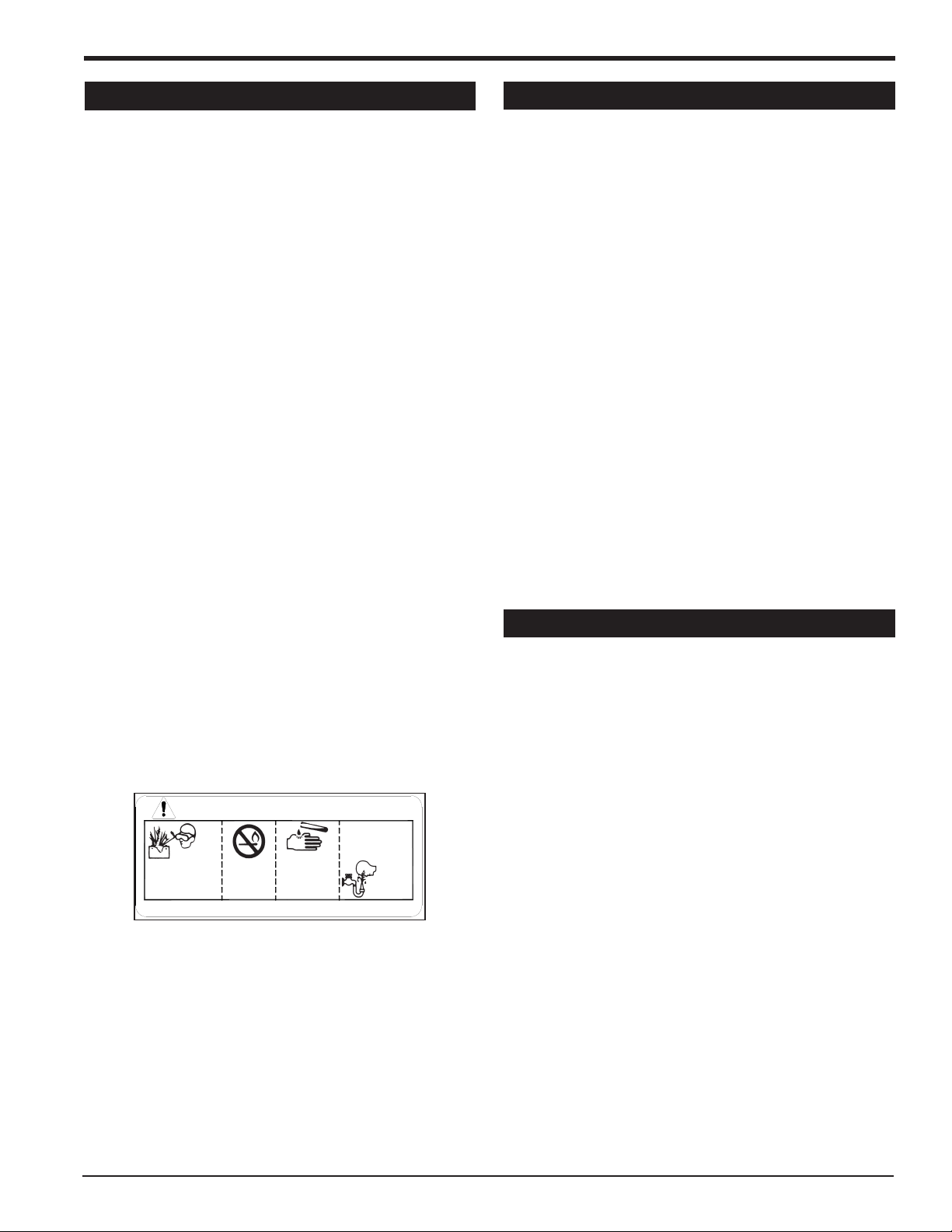
DANGER / POISON
SHIELD EYES
EXPLOSIVE GASES
CAN CAUSE
BLINDNESS OR
INJURY
NO
• SPARKS
• FLAMES
• SMOKING
SULFURIC
ACID
CAN CAUSE
BLINDNESS OR
SEVERE BURNS
FLUSH EYES
IMMEDIATELY
WITH WATER
GET
MEDICAL
HELP
FAST
KEEP OUT OF THE REACH OF CHILDREN. DO NOT TIP. KEEP VENT CAPS TIGHT AND LEVEL.
1.5 BATTERY SAFETY
Improper use and care of the battery on electric start models can result in serious personal injury or property damage. Always observe the following safety precautions.
1. Poison/Danger - Causes Severe Burns. The battery
contains sulfuric acid. Avoid contact with skin, eyes
or clothing. Keep out of reach of children.
ANTIDOTE-External Contact: Flush immediately
with lots of water.
ANTIDOTE-Internal: Drink large quantities of water
or milk. Follow with milk of magnesia, beaten egg
or vegetable oil. Call a physician immediately.
ANTIDOTE-Eye Contact: Flush with water for 15
minutes. Get prompt medical attention.
2. The battery produces explosive gases. Keep sparks,
flame or cigarettes away. Ventilate area when charging battery. Always wear safety goggles when working
near battery.
3. The battery contains toxic materials. Do not damage
battery case. If case is broken or damaged, avoid
contact with battery contents.
4. Neutralize acid spills with a baking soda and water
solution.
5. Properly dispose of a damaged or worn-out battery.
Check with local authorities for proper disposal methods.
6. Do not short circuit battery. Severe fumes and fire
can result.
7. Before working with electrical wires or components,
disconnect battery ground (negative) cable first. Disconnect positive cable second. Reverse this order
when reconnecting battery cables.
1.6 MAINTENANCE/STORAGE SAFETY
1. Shut off fuel supply when the unit is not in use.
2. Before inspecting, servicing, storing, or changing an
accessory, shut off power source, disconnect spark
plug wire from spark plug and make sure all moving
parts have come to a complete stop.
3. Replace any missing or unreadable safety decals. Refer to the parts manual for part numbers when ordering
safety decals from your debris loader dealer.
4. Allow machine to cool before storing in an enclosure.
5. Store the machine out of reach of children and where
fuel vapors will not reach an open ame or spark.
6. Never store this machine with fuel in the fuel tank
inside a building where fumes may be ignited by an
open ame or spark. Ignition sources can be hot water
and space heaters, furnaces, clothes dryers, stoves,
electric motors, etc.
7. Drain the fuel and dispose of it in a safe manner for
storage periods of three months or more.
8. Avoid storing the debris loader hose in direct sunlight
or heat.
1.7 TOWING SAFETY
1. Towing laws may vary in different countries/regions/
states. It is recommended that you contact your local
motor vehicle department for any special rules that
pertain to towing and to know the rules of any country/region/state you may travel through.
2. Connect hitch safety chains. Tighten and secure trailer
hitch bolts. Do not attempt to tow the trailer if vehicle is
not equipped with the proper size hitch ball.
3. Check wheel lug bolts periodically to ensure they are
tight and secure.
4. Place the jack stand on the trailer in the UP position
to clear the ground while towing. Place the jack stand
on a level surface and secure it in the DOWN position
before using the debris loader.
5. Never allow passengers to ride on the debris loader.
Debris Loader Owner’s Manual
3
Page 8
SAFETY
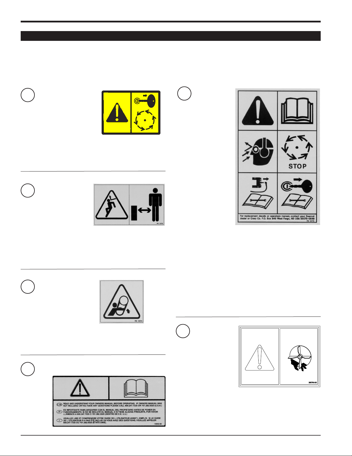
1.8 SAFETY DECALS
See Section 1.9 for decal locations. Familiarize yourself with all of the safety and operating decals on the machine
and the associated hazards. See the engine owners manual or contact the engine manufacturer for engine safety instructions and decals. Make certain that all safety and operational decals on this machine are kept clean and in good
condition. Refer to the parts catalog if you need a replacement decal. Decals that need replacement must be applied
to their original locations.
PN 18993-00
1
DO NOT REMOVE COVER UNLESS KEY IS REMOVED AND
ALL MOVING PARTS HAVE STOPPED. USE ACCESS FOR
CLEANOUT OR INSPECTION ONLY. DO NOT OPERATE
MACHINE WITH ACCESS COVER REMOVED.
PN 12173
2
DO NOT OPERATE THIS EQUIPMENT IN THE VICINITY OF
BYSTANDERS. DO NOT ALLOW CHILDREN TO OPERATE
THIS EQUIPMENT. ALWAYS STAND CLEAR OF DISCHARGE
AREA WHEN OPERATING THIS MACHINE. KEEP FACE AND
BODY AWAY FROM DISCHARGE AREAS.
PN 12172
5
READ AND UNDERSTAND THIS OWNER/OPERATORS
MANUAL. BE COMPLETELY FAMILIAR WITH THE CONTROLS
AND THE PROPER USE OF THIS EQUIPMENT.
OBTAIN AND WEAR SAFETY GLASSES AND USE HEARING
PROTECTION AT ALL TIMES WHEN OPERATING THIS
MACHINE.
PN 12174
3
DO NOT OPERATE MACHINE WITHOUT SHIELDS IN PLACE.
FAILURE TO DO SO MAY CAUSE SERIOUS INJURY OR
DEATH.
PN 14942-00
4
4
Debris Loader Owner’s Manual
BEFORE INSPECTING OR SERVICING ANY PART OF THIS
MACHINE, SHUT OFF POWER SOURCE, REMOVE THE
KEY, DISCONNECT SPARK PLUG WIRE FROM SPARK PLUG
AND MAKE SURE ALL MOVING PARTS HAVE COME TO A
COMPLETE STOP.
PN 36176-00
6
KEEP HANDS AND ANY OTHER BODY PART OUT OF THE
FAN HOUSING WHILE MACHINE IS OPERATING TO AVOID
SERIOUS INJURY OR DEATH. STOP AND ALLOW MACHINE
TO COME TO A COMPLETE STOP BEFORE CLEARING
OBSTRUCTIONS.
Page 9
SAFETY
1.9 SAFETY DECAL LOCATIONS
1.9.1 12 INCH MODELS
The numbers below correspond to the decals in Section 1.8. Familiarize yourself with all of the safety and operational
decals on the machine and the associated hazards. See the engine owners manual or contact the engine manufacturer
for engine safety instructions and decals. Make certain that all safety and operating decals on this machine are kept
clean and in good condition. Refer to the parts catalog if you need a replacement decal. Decals that need replacement
must be applied to their original locations.
NOTE
Model DL12670 (75124) shown. Decals on model
DL12725 are similar in location.
2
* DECALS LOCATED ONLY ON MODEL DL12670 (75124).
** DECALS LOCATED ONLY ON MODEL DL12725.
2
4
1
6*
3**
5
Debris Loader Owner’s Manual
5
Page 10

SAFETY
2
4
5
1.9 SAFETY DECAL LOCATIONS
1.9.2 HITCH MOUNT MODELS
The numbers below correspond to the decals in Section 1.8. Familiarize yourself with all of the safety and operational
decals on the machine and the associated hazards. See the engine owners manual or contact the engine manufacturer
for engine safety instructions and decals. Make certain that all safety and operating decals on this machine are kept
clean and in good condition. Refer to the parts catalog if you need a replacement decal. Decals that need replacement
must be applied to their original locations.
1
6
Debris Loader Owner’s Manual
Page 11

2
HITCH
POLE
1/2” x 4”
BOLTS
1/2” NUTS
5/8” x 4-1/2”
ASSEMBLY
Section
2.1 ATTACH THE WHEELS (12" MODELS)
1. Raise the debris loader frame by using a hoist or
jack.
2. Align the wheel lug holes on the wheel with the wheel
studs on the axle hub.
3. Thread the 1/2" wheel nuts onto the wheel studs. Follow a star pattern when tightening wheel nuts. Torque
to 80-95 ft-lbs.
4. Repeat for the remaining wheel.
IMPORTANT
Check wheel nut torque after the first 8 hours. Re-torque
to 80-95 ft-lbs. if needed. Re-check for proper torque
monthly. Repeat every time tires are removed and reassembled.
2.2 ATTACH THE HITCH (12" MODELS)
2.2.1 670cc HONDA MODELS
3. Using eight 3/8" x 3/4" capscrew bolts, sixteen washers and eight nylock nuts, bolt the hitch assembly to
the trailer.
4. Adjust the hitch coupler to the desired height with
the two 5/8" x 4-1/2" bolts at the front of the coupler
receiver weldment.
1. Make sure the correct end of the hitch pole is facing the
trailer. Run the wiring harness through the hitch pole.
2. Determine which set of hitch pole holes to use in order
to achieve the desired distance from the tow vehicle.
There are four sets of holes.
3. Slide the hitch pole into the hitch mount channel on the
debris loader frame (see Figure 1).
4. Attach the hitch pole to the frame using 1/2" x 4" bolts
and center lock nuts provided in the owner's kit. Tighten
hardware to 75 ft-lbs.
5. Attach the 2" hitch coupler to the front of the hitch pole
with two 1/2" x 4" bolts and center lock nuts.
2.2.2 725cc KOHLER MODELS
1. Using two 1/2" x 4" bolts, adjust the coupler receiver
weldment in or out of the hitch assembly to the desired
position (Figure 2).
2. Slide the hitch assembly into the hitch channel at the
front of the trailer weldment.
Figure 1, Hitch attachment, DL12670 (75124)
COUPLER
HITCH
ASSEMBLY
1/2” x 4”
3/8” x 3/4”
CAPSCREW
BOLT
Figure 2, Hitch attachment, DL12725
RECEIVER
WELDMENT
BOLT
COUPLER
HITCH
BOLT
Debris Loader Owner’s Manual
7
Page 12

ASSEMBLY
2.3 ATTACH THE VACUUM HOSE
2.3.1 670cc HONDA MODELS
1. Connect the hose to the hose support. To do so, place
an end link from each chain through the hooks provided
in the hose support weldment as shown in Figure 3.
2.3.3 HITCH MOUNT MODELS
1. Fasten the hose inlet adapter to the fan intake weldment with the two provided knobs.
2. Assemble the two hose support weldments together
by using the 1/2" x 2-3/4" bolt, spacer and 1/2" center
lock nut provided in the owner's kit (Figure 5).
3. Insert the hose support assembly into the fan housing
spacer (Figure 4).
4. Connect the hose wraps to the hose support. To do so,
place a chain link from each chain wrap in the hose
support hooks.
HOSE
SUPPORT
HOSE
SPACER
HOSE INLET
ADAPTER
KNOB
FAN INTAKE
WELDMENT
HOSE
SUPPORT
HOOKS
1/2” X 2-3/4”
BOLT
1/2” NUT
Figure 3, Attaching hose to hose support
2.3.2 725cc KOHLER MODELS
1. Use the hose clamp to fasten the hose on the fan intake
weldment (Figure 4).
2. Connect the hose wraps to the hose support. To do so,
place a chain link from each chain wrap in the hose
support hooks.
Figure 5, Hose support assembly (Hitch mount models)
Figure 4, Hose attachment, DL12725
8
Debris Loader Owner’s Manual
Page 13

ASSEMBLY
BOLT
3/8” x 1-1/4”
NUT
3/8” NYLOCK
CLAMP
DISCHARGE
SPACER
SHIM
TUBE
DISCHARGE
BLOWER
2.4 ATTACH BLOWER DISCHARGE
2.4.1 670cc MODELS
1. Slide the blower tube discharge clamp underneath the
mounting flange on the debris loader frame.
2. Install the second half of the shim, spacer and clamp
(included in owner's kit) to the tube and flange with 3/8"
x 1-1/4" bolts and nylock nuts (Figure 6). Rotate the
tube 360 degrees to make sure it is mounted correctly.
Lock it in place with the lock lever.
2.6 DISCHARGE TRANSITION (725cc MODELS)
1. Slide the flex hose and clamp ring over the end of the
discharge tube.
2. Evenly tighten the four 3/8" bolts in the ring clamp to
fasten the hose to the discharge tube.
2.7 CONNECT THE BATTERY (12" MODELS)
The machine may or may not have been shipped with
a battery depending on your area. If you did not receive
a battery with your machine, you will need to purchase
one.
Use a battery that meets or exceeds the following
specications:
Nominal Voltage: 12V
CCA @ 0 Degrees: 240
CA @ 32 Degrees: 335
Size: 7-3/32" x 7-11/16" x 5-1/8"
Rated Capacity: 33.0 AH
Terminal Type: M6 bolt and nut
Figure 6, Blower discharge, DL12670 (75124)
2.4.2 ALL OTHER MODELS
1. Point the discharge tube weldment in the desired direction. Then, place the tube on the debris loader frame
mounting flange.
2. Attach the discharge tube weldment to the mounting
flange with six 3/8" x 1-1/4" bolts, twelve flat washers
and six nylock nuts.
2.5 DISCHARGE SUPPORT (725cc MODELS)
1. Connect one end of the discharge support tube to the
clevis at the end of the discharge tube. Use a 5/16" x
2" bolt, two washers and one nylock nut.
2. Connect the other end of the discharge support tube
to the trailer frame clevis located between the engine
and battery. Use a 5/16" x 2" bolt, two washers and
one nylock nut.
To connect the battery:
1. Open the battery box and insert a 12V battery of proper
specifications (see above) into the battery box.
2. Attach the positive (red) battery cable from the engine
to the positive battery terminal.
3. Attach the negative (black) battery cable from the
engine to the negative battery terminal.
4. Secure the cover on the battery box with the tarp
strap.
Debris Loader Owner’s Manual
9
Page 14

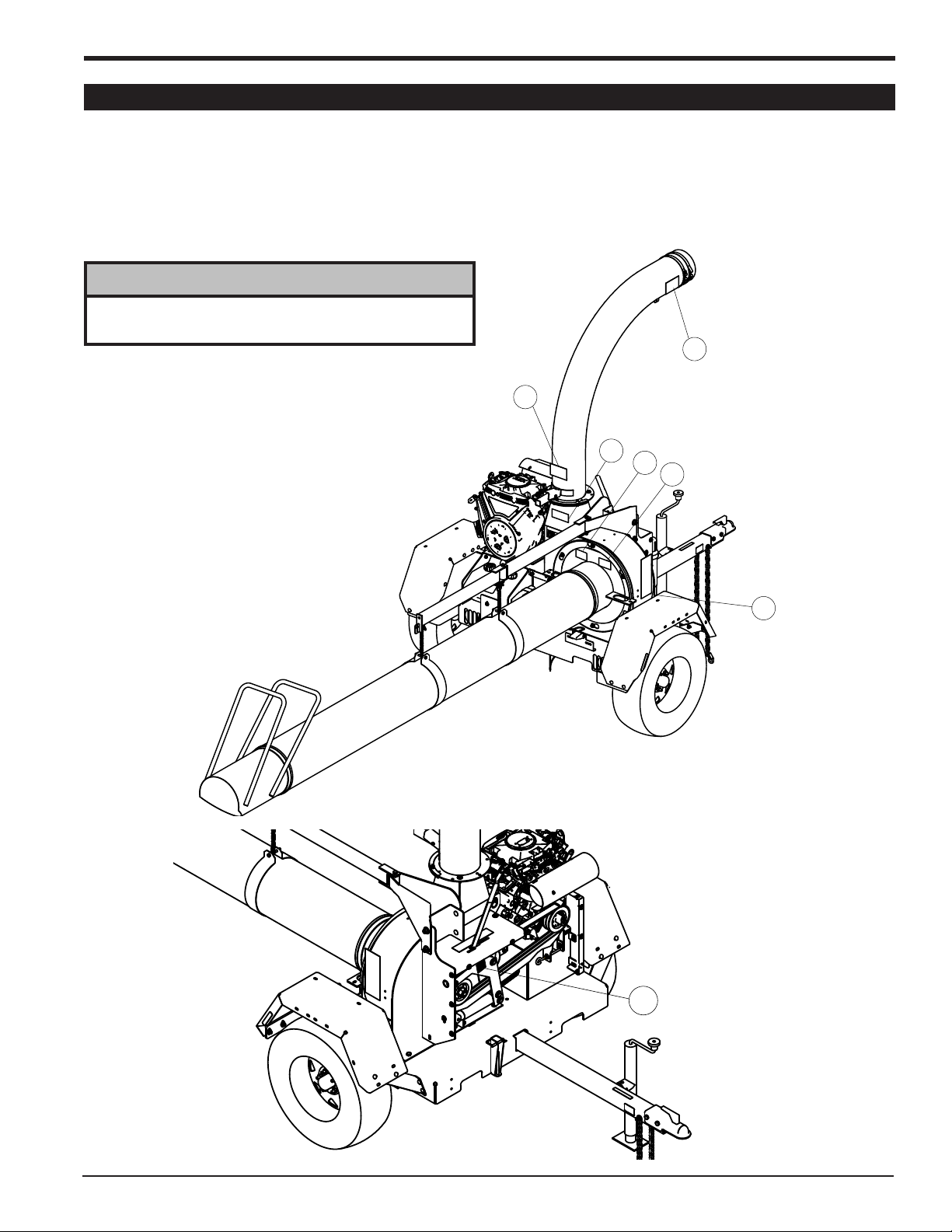
SAFETY CHAINS
3
FEATURES & CONTROLS
Section
3.1 DL12670 (75124) CONTROLS
DISCHARGE TUBE
DISCHARGE TUBE
HANDLE
AVAILABLE KITS
KIT PART NUMBER
CHUTE EXTENSION KIT 75888-00
HOSE
SUPPORT
HOSE HANDLE
FUEL
TANK
BATTERY BOX
MANUAL
HOLDER
ENGAGEMENT
LEVER
BELT SHIELD
HITCH JACK
HOSE
HOLDER
10
Figure 7, DL12670 (75124) controls
Debris Loader Owner’s Manual
Page 15

DISCHARGE TUBE
HITCH
POLE
3.2 DL12725 CONTROLS
HOSE
SAFETY
HITCH JACK
FEATURES & CONTROLS
AVAILABLE KITS
KIT
CHUTE EXTENSION KIT 75873-00
LIGHTS KIT 75754-00
TOOL BAR KIT 75761-00
PART
NUMBER
MANUAL
HOLDER
FUEL
TANK
HANDLE
HOSE
HOLDER
DISCHARGE TUBE
HOSE
SUPPORT
DISCHARGE
SUPPORT
BATTERY BOX
CHAINS
3.3 HITCH MOUNT CONTROLS
AVAILABLE KITS
KIT PART NUMBER
CHUTE EXTENSION KIT 75888-00
LIGHTS KIT 75754-00
Figure 8, DL12725 controls
HOSE HANDLE
HOSE SUPPORT
Figure 9, Hitch mount controls
Debris Loader Owner’s Manual
11
Page 16

FEATURES & CONTROLS
3.4 ENGINE CONTROLS
1. Engine choke: Use when starting a cold engine. Move
to ON position when starting. Move to OFF position
when engine is running. Full choke may not be necessary when starting a warm engine. In this case, partial
or no choke may work best.
2. Fuel cut-off switch: Move to the ON position to start
and run engine. Move to OFF position when engine
is stopped.
3. Engine throttle: Changes engine speed. Push lever
all the way to the fast position for full throttle operation.
Push the opposite way for engine idle. Push all the way
to the slow position to shut engine off. Refer to engine
manual for further engine operating instructions.
4. Engine switch: Turn to ON position to start and run
engine. To stop, turn to OFF position.
5. Starter cord: To start, pull the cord until light resistance
is felt and then pull briskly.
Figure 10, 390cc Honda engine controls
Figure 12, 570cc Briggs engine controls
12
Figure 13, 725cc Kohler engine controls
Figure 11, 670cc Honda engine controls
Debris Loader Owner’s Manual
Page 17

4
OPERATION
Section
4.1 ATTACHING/UNHOOKING DEBRIS LOADER
4.1.1 ATTACHING 12 INCH MODELS
1. Using the hitch jack, raise the trailer hitch until the
coupler is above the height of the hitch ball on the
towing vehicle.
2. Back up the towing vehicle to position the hitch ball
directly beneath the coupler.
3. Open the coupler latch and lower the trailer hitch until
the coupler fully engages the hitch ball.
4. Close the coupler latch, securing the coupler to the
hitch ball.
5. Cross the safety chains under the hitch and connect
to towing vehicle.
6. Raise the jack stand and secure it against the hitch
pole with a pin.
7. Connect the trailer wire harness to the towing vehicle
harness. Test the trailer lights to ensure they are functioning properly.
4.1.2 ATTACHING HITCH MOUNT MODELS
4.1.4 UNHOOKING HITCH MOUNT MODELS
1. Adequately support the debris loader with a jack or
hoist. The unit weighs approximately 280 pounds
(127 kg).
2. Remove the pin from the hitch tube.
3. Slowly pull the towing vehicle away from the debris
loader.
4.2 STARTING THE MACHINE
DANGER
BE PREPARED. On 725cc, 570cc & 390cc models,
the hose inlet starts to vacuum debris as soon as the
engine starts.
CAUTION
Move the machine to a clear, level area outdoors
before starting. Do not operate in the vicinity of
bystanders. Make sure the cutting chamber is empty
before starting.
1. Use a jack or hoist to raise the unit, so the debris loader
hitch tube is even with the vehicle hitch channel.
2. Back the towing vehicle up to the debris loader. Slide
the hitch tube into the vehicle hitch channel.
3. Fasten the hitch tube in the hitch channel with receiver
hitch pin.
4.1.3 UNHOOKING 12 INCH MODELS
1. Unhook the safety chains from the towing vehicle.
Latch safety chains to the hitch.
2. Disconnect the trailer wiring harness from the towing
vehicle. Stow it on the trailer hitch.
3. Lower the debris loader jack stand.
4. Unlatch the coupler. Raise the unit with the jack stand
until the coupler clears the hitch ball.
5. Slowly pull the towing vehicle away from the debris
loader.
4.2.1 ELECTRIC START MODELS
1. Check engine oil level before starting. Add oil if low,
but do not overfill.
2. Make sure the hose inlet is free from debris.
3. Point the discharge tube in the correct direction.
4. On 670cc Honda models, ensure the belt engagement
lever is in the START position.
5. Move choke to the ON position (If restarting a warm
engine, partial or no choke may be necessary).
6. Move the throttle to between half and full throttle.
7. Turn the key and release it when the engine starts.
Allow the key to return to the ON position.
8. Release the key if the engine fails to start within 10
seconds. Allow a 60 second cool down period between
starting attempts if the engine does not start. Failure to
follow these guidelines can cause permanent damage
to the starter.
Debris Loader Owner’s Manual
13
Page 18

OPERATION
4.2 STARTING THE MACHINE
9. Gradually move the choke lever to the OFF position
as the engine warms.
10. Gradually move the throttle to the full throttle position.
11. On 670cc Honda models, engage the fan by moving
the engagement lever to the VACUUM position.
4.2.2 RECOIL START MODELS
1. Check engine oil level before starting. Add oil if low,
but do not overfill.
2. Make sure the hose inlet is free from debris.
3. Point the discharge tube in the correct direction.
4. Turn the fuel cut-off switch to ON.
5. Turn the engine switch to the ON position.
6. Move choke to the ON position (If restarting a warm
engine, partial or no choke may be necessary).
7. Move the throttle to between half and full throttle.
8. Pull the recoil starter until light resistance is felt. Then,
pull briskly. Make sure the starting cord retracts. Repeat
until engine starts.
9. Move the choke to the RUN position.
10. Gradually move the choke lever to the OFF position
as the engine warms.
11. Gradually move the throttle to the full throttle position.
4.5 VACUUMING TIPS AND SAFETY
1. Keep hands or any other part of body or clothing away
from the hose inlet, discharge chute, or any moving
part.
2. Maintain proper balance and footing at all times.
3. Be careful when vacuuming around gravel, gardens,
lawn ornaments, etc.
4. Keep hose as straight as possible during operation in
order to prevent plugging.
5. Use a sweeping motion when vacuuming debris.
6. For maximum suction, keep nozzle close to debris, but
do not block air flow into the nozzle.
7. To extend hose life, periodically rotate the hose on the
fan housing and intake nozzle. This will promote even
wear on the hose.
4.6 TRANSPORTING
4.6.1 12 INCH MODELS
1. Turn off the machine and wait for all moving parts to
stop.
2. Secure vacuum hose in the hose holder weldment
with a snap pin.
3. Ensure hitch jack is secured in the up position and
safety chains are properly attached to the towing
vehicle.
4.3 STOPPING THE MACHINE
1. Gradually move throttle to the slowest position.
2. Turn the engine switch to OFF.
3. If applicable, turn the fuel cut-off switch to OFF.
4.4 VACUUMING OPERATION
1. Run engine at full operating speed before starting to
vacuum.
2. On trailer models, remove the snap pin to release the
hose inlet from the hose holder weldment. Insert the
snap pin back into the hose holder for safe keeping.
3. Point the hose inlet towards the debris to be removed.
Use a sweeping motion to remove debris from a large
area.
14
Debris Loader Owner’s Manual
4. Ensure the trailer wiring harness is connected to the
towing vehicle harness and all trailer lights are functioning.
5. Obey road signs and limits.
4.6.2 HITCH MOUNT MODELS
1. Turn off the machine and wait for all moving parts to
stop.
2. Remove the hose assembly by unscrewing the two
knobs that hold it to the fan housing. Store the hose
inside the towing vehicle so it will not drag on the
ground.
3. Obey road signs and limits.
Page 19

5
SERVICE & MAINTENANCE
Section
5.1 SERVICE AND MAINTENANCE SCHEDULE
INSPECTION ITEMS
Check Nuts and Bolts X
Refer to engine
owner's manual
Before each
use
INTERVAL
Every 25
Hrs
Every 50
Hrs
Every 100
Hrs
Every 300
Hrs
Once (1)
a year
Engine Oil
Replace Spark
Plug
Air Filter Element
Replace Fuel Filter X
Check Drive Belt (DL12670) X
Clean Machine X
* Indicates first hours of use
** Service more frequently in dusty conditions
5.2 REFUELING INFORMATION
Check X
Replace X*
X
Check X
Clean X**
Replace X
WARNING
For best results use only clean, fresh, unleaded gasoline.
Purchase gasoline in small quantities and store in
clean, approved containers. DO NOT MIX OIL WITH
GASOLINE.
Gasoline is highly ammable and its vapors are explosive.
To prevent personal injury or property damage:
• Store gasoline only in approved containers, in well
ventilated, unoccupied buildings, away from sparks
or ames.
• Do not ll the fuel tank while the engine is hot or
running, since spilled fuel could ignite if it comes in
contact with hot parts or sparks from ignition.
• Do not start the engine near spilled fuel. Never use
gasoline as a cleaning agent.
Debris Loader Owner’s Manual
Honda engines
Use unleaded gasoline with a pump octane of 86 or higher,
or a research octane of 91 or higher.
Gasohol (up to 10% ethyl alcohol, 90% unleaded gasoline
by volume) is an approved fuel. Other gasoline/alcohol
blends are not approved.
Methanol (up to a maximum of 5% volume) is an approved
fuel. Methanol blends must contain cosolvents and
corrosion inhibitors to protect the fuel system. Gasoline
containing more than 5% methanol may cause engine
problems.
15
Page 20

SERVICE AND MAINTENANCE
5.2 REFUELING INFORMATION
Briggs & Stratton engines
Use unleaded gasoline with a pump octane of 85 or higher,
or a research octane of 90 or higher.
Do not use gasoline containing methanol
Kohler engines
Use unleaded gasoline with a pump octane of 87 or higher,
or a research octane of 90 or higher.
Gasohol (up to 10% ethyl alcohol, 90% unleaded gasoline
by volume) is an approved fuel. Other gasoline/alcohol
blends are not approved.
Methyl Tertiary Butyl Ether (MTBE) and unleaded gasoline
blends (up to a maximum of 15% MTBE by volume) are
approved. Other gasoline/ether blends are not approved.
To Add Gasoline:
1. Stop engine, wait for all parts to stop moving and disconnect spark plug wire. Remove key from key switch.
Allow the engine and mufer to cool for at least three
minutes.
Check the condition of the drive belt annually or after every
25 hours of operation, whichever comes first. Replace a
cracked, frayed, worn or stretched drive belt. To adjust the
drive belt, proceed as follows:
1. Move the engagement lever to the start position.
2. Shut engine off.
3. Disconnect spark plug wire.
4. Remove the belt shield by removing the 11 bolts securing the belt shield to the rotor weldment.
5. Loosen the 5/16" bolt attaching the belt guide to the
engine (Figure 14).
2. Clean area around fuel ll cap and remove cap.
3. Using a clean funnel, ll fuel tank to 1/2" below bottom
of ller neck to provide space for any fuel expansion.
Install fuel ll cap securely and wipe up any spilled
gasoline.
5.3 ENGINE OIL
Check the oil level before each use. If needed, fill the engine
with the type and amount of oil specified in the engine
owner's manual. Do not overfill.
5.4 ADJUSTING DRIVE BELT (670cc MODEL)
WARNING
Before inspecting or servicing any part of this machine,
shut off power source, disconnect spark plug wire from
spark plug and make sure all moving parts have come
to a complete stop.
Figure 14, Drive belt, DL12670 (75124)
6. Move the engagement lever to vacuum position.
7. To increase tension on the belt, do the following:
a. Loosen the four carriage bolts attaching the engine
plate to the trailer (Figure 15).
Figure 15, Engine plate carriage bolts
16
Debris Loader Owner’s Manual
Page 21

SERVICE AND MAINTENANCE
Force of
20 lbs.
Span Length
7/16” Deflection
5.4 ADJUSTING DRIVE BELT (670cc MODEL)
b. Locate the engine plate push off bolt located above
the gas tank. If needed, the gas tank can be removed for better access to the push off bolt.
c. Loosen the jam nut (Figure 16).
Figure 16, Jam nut and push off bolt
d. Tighten the push off bolt to move the engine away
from the rotor housing until the belt deflection is
7/16" when a 20 lb. load is placed against the belt
(Figure 17).
e. Tighten the four carriage bolts securing the engine
plate to the trailer.
f. Tighten the jam nut to ensure the proper deflection
is maintained.
8. Replace the belt if the engine cannot be adjusted any
further and the idler arm comes in contact with the
engagement lever rollers when in the run position.
9. Adjust the lower belt guide so there is 1/8" clearance
between the belt and the belt guide.
10. Move the engagement lever to the start position.
11. Reinstall the belt shield.
12. Reconnect spark plug wire.
5.5 REPLACING DRIVE BELT (670cc MODEL)
WARNING
Before inspecting or servicing any part of this machine,
shut off power source, disconnect spark plug wire from
spark plug and make sure all moving parts have come
to a complete stop.
Check the condition of the drive belt annually or after every
25 hours of operation, whichever comes first. Replace a
cracked, frayed, worn or stretched drive belt. To replace
the drive belt, proceed as follows:
1. Move the engagement lever to the start position.
2. Shut engine off and disconnect spark plug wire.
3. Remove the belt shield by removing the 11 bolts securing the belt shield to the rotor weldment.
4. Loosen and remove the idler pulley (Figure 18).
Figure 18, Drive belt, DL12670 (75124)
5. Loosen the two mounting bolts located at both ends
of the lower belt guide.
Figure 17, Belt tension
6. Loosen the four carriage bolts attaching the engine
plate to the trailer.
7. To release the tension on the belt, loosen the jam nut
and engine plate push off bolt located above the gas
tank. If needed, the gas tank can be removed for better
access to the jam nut and push off bolt.
8. Remove the old belt and install the new belt.
9. Reinstall the idler pulley.
10. Move the engagement lever to vacuum position.
11. Adjust the drive belt tension so that the belt deflection
is 7/16" when a 20 lb. load is placed against the belt
(Figure 17).
Debris Loader Owner’s Manual
17
Page 22

SERVICE AND MAINTENANCE
5/16”
NYLOCK NUT
5.5 REPLACING DRIVE BELT (670cc MODEL)
12. Tighten the four carriage bolts securing the engine
plate to the trailer.
13. Tighten the jam nut to ensure the proper deflection is
maintained.
14. Reinstall belt guide. Adjust so there is 1/8" clearance
between the belt and the belt guide.
15. Move the engagement lever to the start position.
16. Reinstall the belt shield.
17. Reconnect spark plug wire.
5.6 REPLACING THE FLEX HOSE
Check the condition of the flex hose frequently. Replace
if it is split or damaged.
1. Shut off engine and allow rotor to completely stop.
2. Remove spark plug wire.
3. Remove the clamp attaching the flex hose to the hose
intake weldment. Remove the hose from the intake
weldment (Figure 19).
4. Remove two bolts from the hose wraps to separate
the flex hose from the hose support.
5. Remove the remaining clamp securing the flex hose
to the hose handle. Remove the hose from the hose
handle.
6. Replace flex hose by performing steps 1-5 in reverse
order.
5.7 REPLACING WEAR LINERS
WARNING
Before inspecting or servicing any part of this machine,
shut off power source, disconnect spark plug wire from
spark plug and make sure all moving parts have come
to a complete stop.
The fan housing wear liners are replaceable on 725cc,
570cc & 390cc engine models. To replace the wear
liners:
1. Remove the fan intake weldment from the fan housing.
2. Remove the 7/16" x 1-1/2" bolt and washers from the
end of the engine crank shaft (Figure 20).
3. Remove the bushing and rotor from the engine crank
shaft.
4. From the outside of the debris loader housing, remove
eight 5/16" nylock nuts that hold the two wear liners.
5. Remove the old wear liners and insert the new liners.
6. Install the new wear liners with eight 5/16" x 3/4" carriage bolts and nylock nuts. Feed the carriage bolts
from inside the debris loader housing. Torque hardware
to 17 ft-lbs.
7. Reinstall the bushing and rotor on the engine crank
shaft.
8. Reinstall the 7/16" x 1-1/2" bolt and washers to the
engine crank shaft. Torque to 50 ft-lbs.
9. Make sure approximately 1/4" clearance exists between the fan housing and the rotor plate.
Figure 19, Flex hose (670cc Honda model shown)
18
WASHERS
7/16” x
1-1/2” BOLT
Figure 20, Flex hose (670cc Honda model shown)
Debris Loader Owner’s Manual
BUSHING
ROTOR
5/16” x 3/4”
CARRIAGE
WEAR
LINERS
BOLT
Page 23

5.8 TRAILER SERVICE
1. Check wheel lug nut torque after the first 8 hours of towing. Check monthly thereafter.
2. Check air pressure in tires after the first 8 hours of towing.
Check monthly thereafter. Fill tires to 60 PSI.
3. Check and repack wheel bearings with grease every
year.
4. Always connect the safety chains when towing. Ensure
trailer hitch bolts are tight and secure.
5. Check trailer lights.
5.9 GREASABLE BEARINGS (670cc MODEL)
Greasable bearings can be found on 670cc Honda engine
models. Mounted bearings are pre-lubricated at our factory
and are ready for operation.
SERVICE AND MAINTENANCE
Grease Zerk
.18 OZ
5 GRAMS
Figure 21, Grease zerk, DL12670 (75124)
RELUBRICATION:
Relubrication of bearings is determined by operating conditions and environment. Lubricate standard bearings with a
LITHIUM based grease. Greasing intervals and quantities
are shown on Figure 21 using the following symbol:
Frequency (50 hours)
Quantity
GREASING INTERVALS:
Bearings in extreme environments will require more frequent greasing intervals.
GREASE FILL AMOUNTS:
It is preferred that experience dictate fill amounts due to
wide variances in applications, greasing equipment and
operating conditions. The quantity shown is the recommended amount. In most cases, it is best to lubricate in
small amounts, under low pressure, until a thin bead of
fresh grease is visible at the seal lip area.
Recommended
Qty. of grease.
5.10 UNPLUGGING THE ROTOR
WARNING
Before inspecting or servicing any part of this machine,
shut off power source, disconnect spark plug wire from
spark plug and make sure all moving parts have come
to a complete stop.
The debris loader is designed to be used in fairly dry
conditions. Wet material, along with too much debris and
large sticks, can plug the rotor or hose. A plugged rotor
bogs down the engine and can possibly stop the engine if
the rotor is severely plugged. To clear the rotor:
5.10.1 12 INCH MODELS
1. Shut off engine and allow rotor to completely stop.
2. Remove spark plug wire.
3. Remove the access bolt (Figure 22).
Care should be taken when greasing bearings to avoid
overfilling. Overfilling can lead to excessive heat and/or unseating of the seals. Grease should be introduced in small
amounts and under light pressure. Whenever possible, the
bearing should be rotated slowly while grease is added to
ensure equal distribution throughout the raceways.
Debris Loader Owner’s Manual
Figure 22, Access bolt
19
Page 24

SERVICE AND MAINTENANCE
5.10 UNPLUGGING THE ROTOR
4. On DL12725 models, loosen the six 5/16" nuts that
hold the intake weldment to the frame.
5. Turn the intake weldment clockwise to remove it.
6. Check the hose for clogs and clear debris from the
rotor.
7. Turn the rotor by hand to verify it is unplugged.
8. Place the intake weldment over the six frame nuts and
turn it counterclockwise to set the bolts in the weldment notches.
9. On DL12725 models, tighten the 5/16" nuts to 17 ftlbs.
10. Reinstall the access bolt.
11. Reconnect spark plug wire and resume operation.
5.10.2 HITCH MOUNT MODELS
1. Shut off engine and allow rotor to completely stop.
2. Remove spark plug wire.
3. Loosen the six 5/16" nuts that hold the intake weldment
to the debris loader frame.
4. Turn the vacuum intake clockwise to remove it.
5. Check the hose for clogs and clear debris from the
rotor.
6. Turn the rotor by hand to verify it is unplugged.
7. Place the intake weldment over the six frame nuts and
turn it counterclockwise to set the studs in the weldment
notches. Tighten 5/16" nuts to 17 ft-lbs.
8. Reconnect spark plug wire and resume operation.
5.11 UNPLUGGING THE INLET HOSE
1. If the hose becomes plugged during operation, straightening the hose may dislodge the clog.
2. If straightening the hose does not work, shake the hose
in an up and down or side to side motion.
3. If the clog remains after performing the above two
steps, shut the engine off and wait for all moving parts
to stop moving. Then, remove the hose from the fan
housing and manually unplug the hose.
20
Debris Loader Owner’s Manual
Page 25

6
TROUBLESHOOTING
Section
PROBLEM PROBABLE CAUSE REMEDY
Improper control settings Use proper settings.
Lack of fuel Fill fuel tank.
Engine will not start
Engine stalls or stops
Engine overheats
Excessive vibration while
running
Rotor will not turn
Excessive belt wear (670cc
Honda model only)
Internal engine problems Contact dealer.
Spark plug disconnected Connect spark plug.
Dirty, stale or contaminated gas
Plugged rotor Clear rotor.
Vacuuming material too fast Slow vacuuming rate.
Cooling system plugged Clean Cooling fans and fins.
Improper oil level
Drive system vibration
Drive belt too loose or broken Adjust or replace.
Plugged rotor Clear rotor.
Not using correct belt
Pulley damaged or worn Replace pulley.
Pulley not in alignment Align pulley with straight edge.
Belt tension too loose Tighten belt or replace.
Refill gas tank with fresh, clean, unleaded
regular gasoline.
Fill engine to correct oil level. Refer to
engine operator’s manual.
Check drive belts and pulleys
for bad or worn areas.
Contact authorized dealer
to order belts.
Trailer swings during
towing
Plugged discharge tube
Excessive belt noise Improper belt tension Adjust belt tension or replace.
Engine drives rotor
during startup (670cc
Honda model only)
Engine speeds up; will not
vacuum material
Tire air pressure not correct Check tire sidewall for inflation limits.
Engine speed too slow Increase engine speed.
Vacuuming too much material
into the machine
Engagement lever is
in the run position
Incorrect belt tension Adjust belt tension or replace.
Inlet hose is plugged
Debris Loader Owner’s Manual
Vacuum debris at a slower rate.
Put the engagement lever
in the start position.
Shake hose in an up and down or side to
side motion in order to dislodge debris.
21
Page 26

7
SPECIFICATIONS
Section
7.1 DEBRIS LOADER SPECIFICATIONS
DL12670 DL12725 DL10570 DL8390
Flex Hose Size 12" dia. x 10' 12" dia. x 6-1/4' 10" dia. x 12.5' 8" dia. x 12.5'
Rotor Size 19.88" x 7" 19.88" x 5.44" 16.25" x 6.13" 16.25" x 6.13"
Discharge Tube
Size
Chute Rotation 360 degrees 360 degrees 360 degrees 360 degrees
Drive Type Belt Shaft Shaft Shaft
Belt Size 2B70 N/A N/A N/A
Weight (lbs.) 1022 lbs. 850 lbs. 280 lbs. 280 lbs.
Tires P215/70R15 P215/70R15 N/A N/A
Engine Honda 670cc gasoline Kohler 725cc gasoline
Specifications are subject to change due to design modifications.
8" dia. 8" dia. 8" dia. 8" dia.
Briggs & Stratton
Vanguard 570cc
gasoline
Honda 390cc gasoline
22
Debris Loader Owner’s Manual
Page 27

SPECIFICATIONS
7.2 BOLT TORQUE
The tables below are for reference purposes only and their use by anyone is entirely voluntary, unless otherwise
noted. Reliance on their content for any purpose is at the sole risk of that person and any loss or damage resulting
from the use of this information is the responsibility of that person.
ENGLISH TORQUE SPECIFICATIONS
SAE
Grade
and
Head
Markings
SAE - 2
SAE - 5
SAE - 8
BOLT DIAMETER
BOLT TORQUE *
BOLT DIAMETER
SAE 2 SAE 5 SAE 8
N.m Ft-lb. N.m Ft-lb. N.m Ft-lb.
1/4" 7.5 5.5 11 8 16 12
5/16" 15 11 23 17 34 25
3/8" 27 20 41 30 61 45
7/16" 41 30 68 50 95 70
1/2" 68 50 102 75 149 110
9/16" 97 70 149 110 203 150
5/8" 122 90 203 150 312 230
3/4" 217 160 353 260 515 380
7/8" 230 170 542 400 814 600
1" 298 220 786 580 1220 900
1-1/8" 407 300 1085 800 1736 1280
1-1/4" 570 420 2631 1940 2468 1820
METRIC TORQUE SPECIFICATIONS
A
METRIC
Grade
and
Head
Markings
4.8
4.8
8.8
8.8 10.9
10.9
12.9
12.9
BOLT DIAMETER
A
BOLT TORQUE *
BOLT DIAMETER
4.8 8.8 10.9 12.9
N.m Ft-lb. N.m Ft-lb. N.m Ft-lb. N.m Ft-lb.
M3 0.5 0.4 - - - - - -
M4 3 2.2 - - - - - -
M5 5 4 - - - - - -
M6 6 4.5 11 8.5 17 12 19 14.5
M8 15 11 28 20 40 30 47 35
M10 29 21 55 40 80 60 95 70
M12 50 37 95 70 140 105 165 120
M14 80 60 150 110 225 165 260 190
M16 125 92 240 175 350 255 400 300
M18 175 125 330 250 475 350 560 410
M20 240 180 475 350 675 500 800 580
M22 330 250 650 475 925 675 1075 800
M24 425 310 825 600 1150 850 1350 1000
M27 625 450 1200 875 1700 1250 2000 1500
Torque figures indicated above are valid for non-greased or non-oiled threads and heads unless otherwise specified. Therefore, do not grease or oil
bolts or capscrews unless otherwise specified in this manual. When using locking elements, increase torque values by 5%.
* Torque value for bolts and capscrews are identified by their head markings.
Debris Loader Owner’s Manual
23
Page 28

ECHO Bear Cat
237 NW 12th Street, West Fargo, ND 58078-0849
Phone: 701.282.5520 • Toll Free: 800.247.7335
Fax: 701.282.9522
E-mail: service@crary.com • opesales@crary.com
www.BearCatProducts.com
 Loading...