

Page 1
Instructions
WARNING
SUBJECT: PLUS 1 UPGRADE KIT FOR
8 INCH DOMESTIC (PN 76172-00) AND
Before inspecting or servicing any part of this machine,
shut off power source, remove key, disconnect the
battery cables and make sure all moving parts have
come to a complete stop.
EUROPEAN (PN 76110-00) CHIPPERS
FITS MODELS: 8" CHIPPERS
These instructions will describe how to remove the Smart
CH8670H (76824) AND CH8993H
Relay and install the Plus 1 controller.
(76835)
CONFIRM KILL SWITCH WAS REWIRED
Before installing the Plus 1 controller, confirm that the kill switch has been correctly rewired as described in Service
Bulletin 07-007 (see http://bearcatproducts.com/).
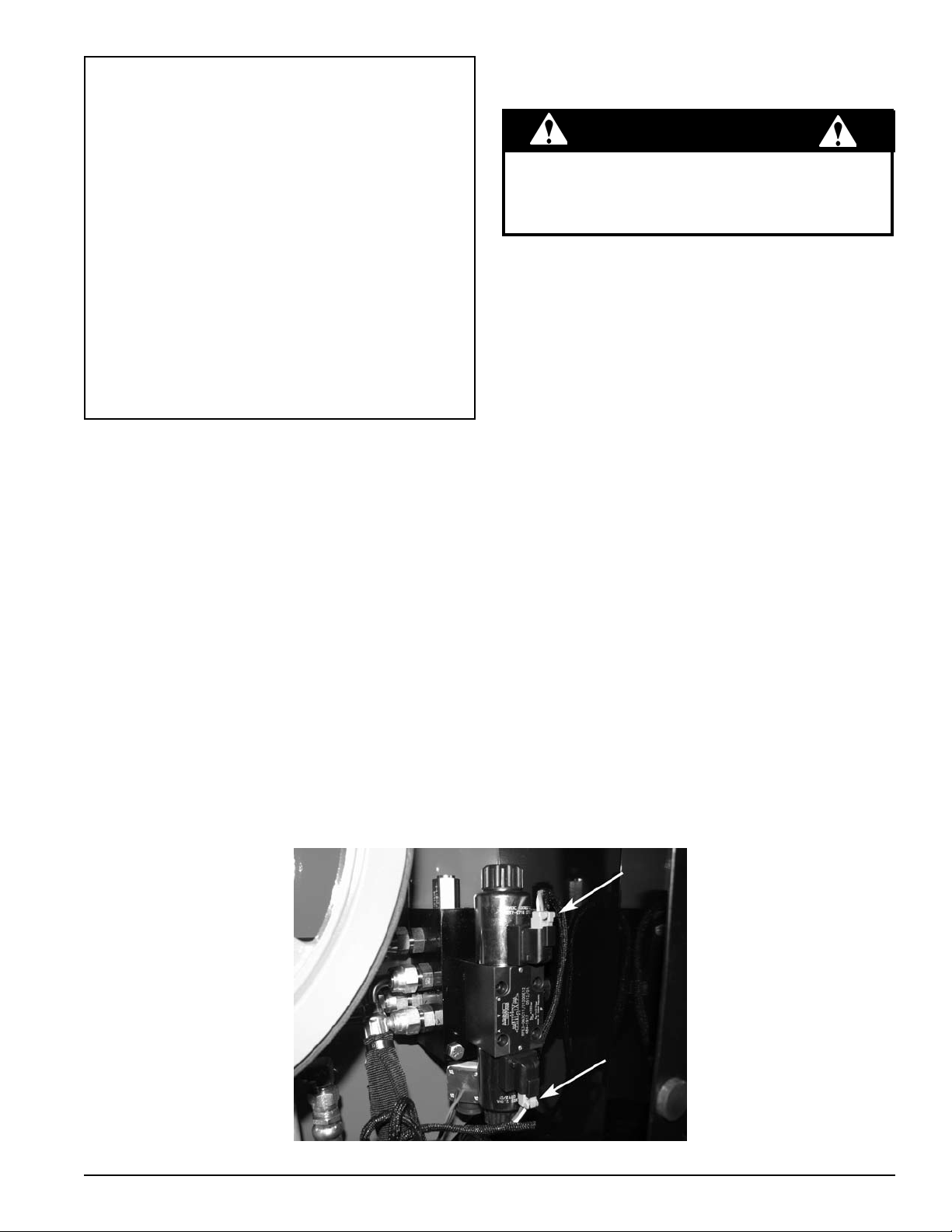
REMOVE SNUBBER HARNESS IF ONE WAS INSTALLED
The Plus 1 Controller will not work if a snubber harness was previously installed on your chipper. To check this, look at
the valve assembly (pictured below).
If your valve assembly looks like the one pictured below• , a snubber harness was not installed on your machine
and you may procede with Plus 1 installation.
If your valve assembly does not look like the one pictured below• because a snubber harness was connected in
the places shown by arrows, you must unplug the connectors, remove the snubber harness, and plug the connectors
back in so that your valve assembly looks like the one shown below.
PN 76111-00
Rev. 051710
Page 2
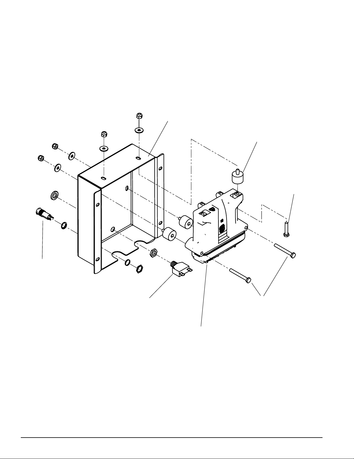
INSTALL PLUS 1 CONTROLLER
RUBBER
BUMPERS
1-1/4”
HEX BOLT
2-1/4”
HEX BOLT
PLUS 1
CONTROLLER
CONTROLLER
ENCLOSURE
CIRCUIT
BREAKER
TRI-COLOR
LED
Install the tri-colored LED in the lower left hole of the controller enclosure by unscrewing the LED hex nut, pushing 1.
the LED into the enclosure from the front, and securing it with the hex nut.
Bolt the Plus 1 controller into the controller enclosure as shown below with four (4) rubber bumpers (two behind the 2.
controller and two on top).
2
Instruction Sheet
Page 3
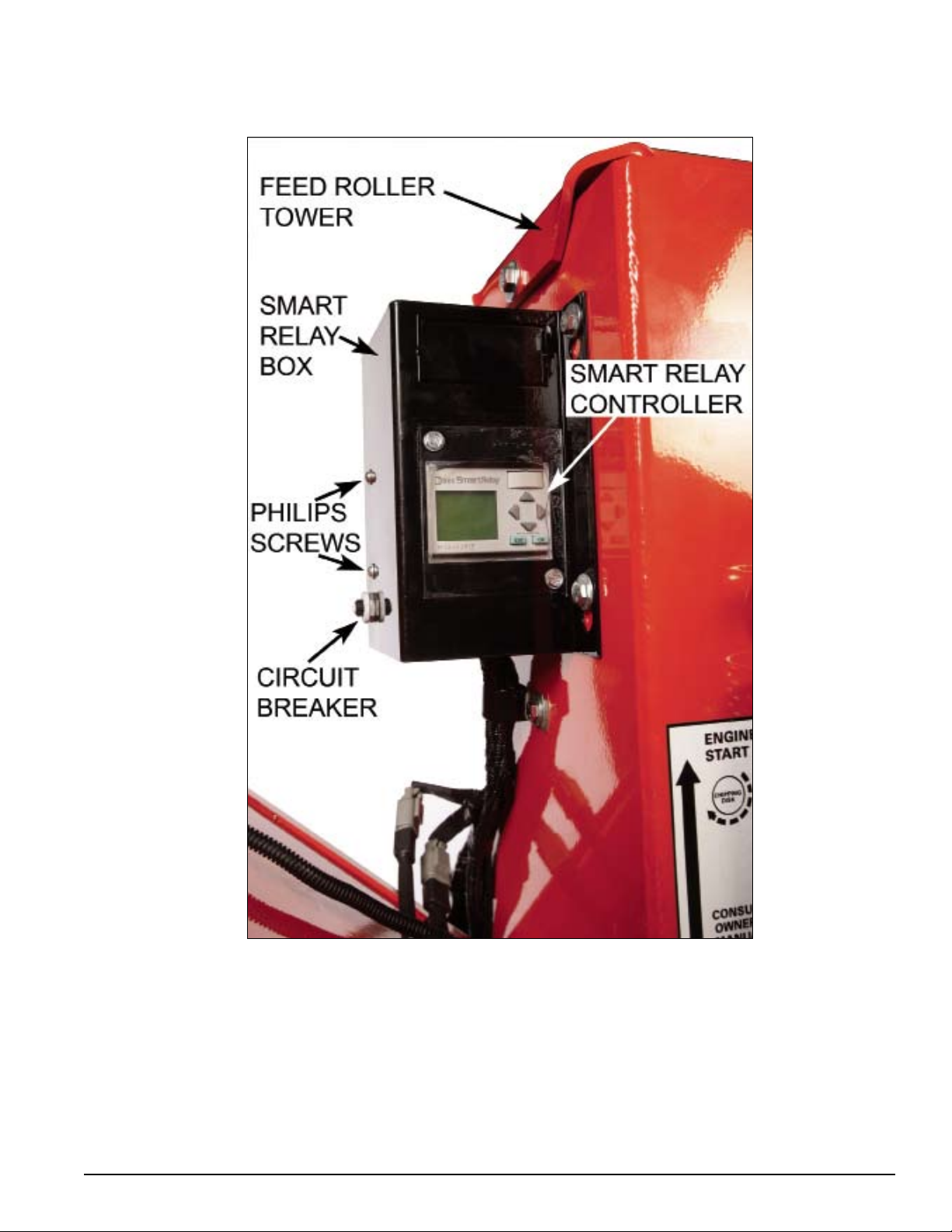
Unbolt the Smart Relay box and remove it from the chipper feed roller tower.3.
Remove the Philips screws and nuts.4.
Transfer the circuit breaker button (see above) and wires connected to it from the Smart Relay box to the right lower 5.
hole in the Plus 1 controller enclosure.
Instruction Sheet
3
Page 4

Next, unclamp the wires from the Smart Relay controller and connect them to the Plus 1 controller harness from the 6.
GREEN/BLACK
ORANGE/BLACK
RED (#1 WIRE)
WHITE
GREEN
ORANGE
BLACK
YELLOW
LIGHT GREEN
RED/BLACK
RED/YELLOW
RED (#3 WIRE)
RED (#2 WIRE)
DO NOT CONNECT TO PLUS 1
HARNESS. TAPE EACH END
INDIVIDUALLY AND THEN
TAPE ALL SIX WIRES
TOGETHER.
CONNECT TO WIRES OF
MATCHING COLOR ON
THE PLUS 1 HARNESS.
CONNECT WIRES FROM THE PLUS 1
HARNESS TO THE TRI-COLORED LED
AS SHOWN HERE.
CHIPPER
HARNESS PN
18547-00
RED (#4 WIRE)
RED/YELLOW
WHITE
BLUE
kit. These wires can be connected to the controller harness in two ways:
Either solder the wires on the controller harness to the wires on the chipper harness or,A.
Use the female and male connectors supplied with the kit.B.
Some of the wires coming from the Plus 1 controller harness will not be used. Three of them will connect to the LED.
The rest will connect to the chipper harness. Use one of the diagrams below to connect the wires correctly. NOTE:
Each wire has a number marked on it. Use these numbers to distinguish between the three different red wires.
DOMESTIC (USA, CANADA, AND SOUTH AMERICA) WIRING
WITHOUT KNEEBAR
4
Instruction Sheet
Page 5

GREEN/BLACK
ORANGE/BLACK
RED (#1 WIRE)
WHITE
GREEN
ORANGE
BLACK
YELLOW
LIGHT GREEN
RED/BLACK
RED/YELLOW
RED (#3 WIRE)
RED (#2 WIRE)
DO NOT CONNECT TO PLUS 1
HARNESS. TAPE EACH END
INDIVIDUALLY AND THEN
TAPE ALL FOUR WIRES
TOGETHER.
CONNECT TO WIRES OF
MATCHING COLOR ON
THE PLUS 1 HARNESS.
CONNECT WIRES FROM THE PLUS 1
HARNESS TO THE TRI-COLORED
LED AS SHOWN HERE.
CHIPPER
HARNESS PN
18547-00
RED (#4 WIRE)
RED/YELLOW
WHITE
BLUE
WIRING FOR EURO MODELS WITH KNEEBAR SAFETY FEATURE
WITH KNEEBAR
After the Plus 1 controller harness wires are all properly connected, plug the controller harness into the Plus 1 7.
controller. Plug the black connector into the black receptor and the grey connector into the grey receptor.
Wrap all exposed wire in electrical tape (not provided) and tuck the wires into the controller enclosure.8.
Instruction Sheet
5
Page 6

Drill four holes 9/32" in diameter in the chipper feed tower to accomodate the new controller. Drill them on the same 9.
.815"
6.0"
8.0"
2.75"
NEW
HOLES
face of the feed tower that the Smart Relay was located. See diagram below for correct placement of holes.
Bolt the Plus 1 controller enclosure onto the chipper in the holes just drilled with four (4) 1-1/4 x 3/4" bolts, washers 10.
and nuts. Thread the bolts through from inside the machine.
OPERATION
Upon initial startup, make sure the chipper is in Neutral position. 1.
Observe the LED light while starting the chipper engine. If the chipper feed control is in any position other than 2.
Neutral, the LED will flash red and forward feed will not be available.
Upon initial startup, if the chipper is in Neutral position, the LED will flash green, indicating that the RPM is not high 3.
enough to chip (see the Optimal Rotor and Engine RPM chart).
Increase RPM gradually until the LED is solid green. Forward feed is now available.4.
See the Control Light Flash codes table on the following page for a complete explaination of all flash codes provided 5.
by the LED.
OPTIMAL ROTOR AND ENGINE RPM
OPTIMAL ROTOR AND ENGINE RPM
Chipper Model Rotor RPM Engine RPM
CH8993H (76835) 1500 3750
CH8670H (76824) 1500 3750
6
Instruction Sheet
Page 7

GUIDE TO THE CONTROLLER FLASH CODES
SIGNAL FREQUENCY CAUSE ACTION TO TAKE
GREEN
Green Solid light Forward feed available. Feed materials into the chute.
Green One flash per second
Red One flash per second
Red Solid light
RPM not high enough to chip
upon initial startup.
Disk RPM dropped while
chipping.
RED
Feed bar is not in STOP upon
initial startup.
RPM dropped too low for 10
seconds.
(European models only) Light
is solid red upon startup.
(European models only)
Safety bar was activated.
(Domestic models only)
Jumper harness plug was
damaged.
Increase RPM gradually until the green light
stops flashing.
The feed roller will automatically reverse to
regulate the feed.
Put control bar in STOP position.
Put control bar in STOP position and then
reengage.
Push reset/override button to reset.
Check connections to jumper harness plug.
Replace if plug necessary (PN 36391-00)
Amber
Amber
Amber
On for 2 seconds and
then off for 2 seconds
Solid light for 7
seconds followed by a
long pause
On for 1/2 second,
then off for 1/2 second
for a period of 8
seconds followed by a
long pause
AMBER
Check the sharpness of the
chipper blades.
There is a short or open
circuit in the forward feed.
There is a short or open
circuit in the reverse feed.
Check sharpness of chipper
blades. Sharpen or flip if necessary.
To reset the controller: With the control bar
in STOP, turn the keyswitch to ON, and then
shift the control bar from reverse to reverse
and back three times within 60 seconds.
Check connections to the forward coil on
the feed hydraulic valve. Replace coil if
necessary.
Check connections to the reverse coil on
the feed hydraulic valve. Replace coil if
necessary.
Instruction Sheet
7
Page 8

PARTS LIST, KIT # 76172-00
PART NUMBER DESCRIPTION QTY.
14624-00 CONNECTOR, 1/4 QD FEMALE 12
14625-00 CONNECTOR 1/4 QD MALE 12
15001 BOLT, 1/4 X 3/4 4
15030 WASHER, 1/4" 8
15197 BOLT, 1/4 X 2-1/4 HEX HD 2
15214 BOLT, 1/4 X 1-1/4 G5 ZP HCS 2
15355 NUT, 1/4 NYLOCK 8
36258-00 CONTROLLER, PLUS 1 CHIPPER 1
36261-00 BUMPER, 1” OD W/1/4” STUD 4
36356-00 LED, TRI-COLOR 12V 3-TERM BASE 1
36399-00 HARNESS, 8” PROGRAM JUMPER 1
76133-12 ENCLOSURE, PLUS 1 MOUNT KIT 1
PARTS LIST, KIT # 76110-00
PLUS 1 CONTROLLER KIT
PLUS 1 CONTROLLER KIT
PART NUMBER DESCRIPTION QTY.
14624-00 CONNECTOR, 1/4 QD FEMALE 12
14625-00 CONNECTOR 1/4 QD MALE 12
15001 BOLT, 1/4 X 3/4" 4
15030 WASHER, 1/4" 8
15197 BOLT, 1/4 X 2-1/4 HEX HD 2
15214 BOLT, 1/4 X 1-1/4 G5 ZP HCS 2
15355 NUT, 1/4 NYLOCK 8
36258-00 CONTROLLER, PLUS 1 CHIPPER 1
36261-00 BUMPER, 1” OD W/1/4” STUD 4
36356-00 LED, TRI-COLOR 12V 3-TERM BASE 1
36382-00 HARNESS, 8” PROGRAM JUMPER 1
76133-12 ENCLOSURE, PLUS 1 MOUNT KIT 1
ECHO BEAR CAT
www.bearcatproducts.com
237 NW 12th Street, West Fargo, ND 58078-0849
Phone: 701.282.5520 • Toll Free: 800.247.7335 • Fax: 701.282.9522
E-mail: service@bearcatproducts.com • sales@bearcatproducts.com
 Loading...