

Page 1
Instructions
5”
4”
WARNING
SUBJECT: PLUS 1 CONTROLLER
INSTALLATION KITS 76170-00 AND
Before inspecting or servicing any part of this machine,
shut off power source, remove key, disconnect the
battery cables and make sure all moving parts have
come to a complete stop.
76171-00
FITS MODELS: 6" CHIPPERS
These instructions will describe how to install the Plus 1
controller.
CH6670H (76624), CH611DH
(76628), CH6993H (76635)
1. CONFIRM KILL SWITCH WAS REWIRED ON CH6670H
Before installing the Plus 1 controller, confirm that the kill switch on the CH6670H has been correctly rewired as described
in Service Bulletin 07-007 (see Distributor/Dealer Tools at http://bearcatproducts.com/).
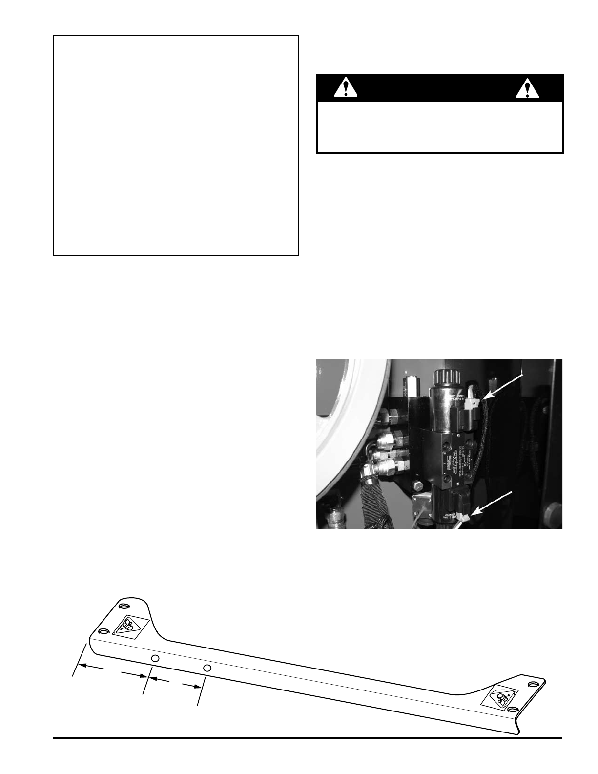
2. REMOVE SNUBBER HARNESS IF ONE WAS PREVIOUSLY INSTALLED
The Plus 1 Controller will not work if a snubber harness
was previously installed on your chipper. To check this,
look at the valve assembly (pictured at right).
If your valve assembly looks like the one pictured,•
a snubber harness was not installed on your machine
and you may procede with Plus 1 installation.
If your valve assembly does not look like the one •
pictured because a snubber harness was connected
in the places shown by arrows, you must unplug the
connectors, remove the snubber harness, and plug
the connectors back in so that your valve assembly
looks like the one shown here.
ENGLISH FRANÇAIS
3. DRILL MOUNTING HOLES
To mount the Plus 1 controller on the engine shield brace, drill two holes 11/32" in diameter in the shield brace in the
positions shown below. They should be drilled on the side of the machine closest to the control panel. (Note: in newer
machines these holes have already been drilled.)
PN 75984-00
Rev. 081110
Page 2

4. MOUNT CONTROLLER
BUMPER
1-1/4” BOLT
2-1/4” HEX
BOLT
PLUS 1
CONTROLLER
5/16” X 3/4”
CARRIAGE
BOLT
CONTROLLER
PLATE
1/4” NYLOCK
NUT
5/16” NYLOCK NUT
ENGINE SHIELD
BRACE
7.50"
1.50"
DRILL HOLE 9/16”
IN DIAMETER
Bolt the controller plate to the engine shield brace with the (2) 3/4" carriage bolts that are provided (see figure 1.
below). Secure with two nuts.
Bolt the Plus 1 controller to the controller plate with two (2) 1" bolts, two (2) 2" hex bolts and four (4) bumpers as 2.
shown below.
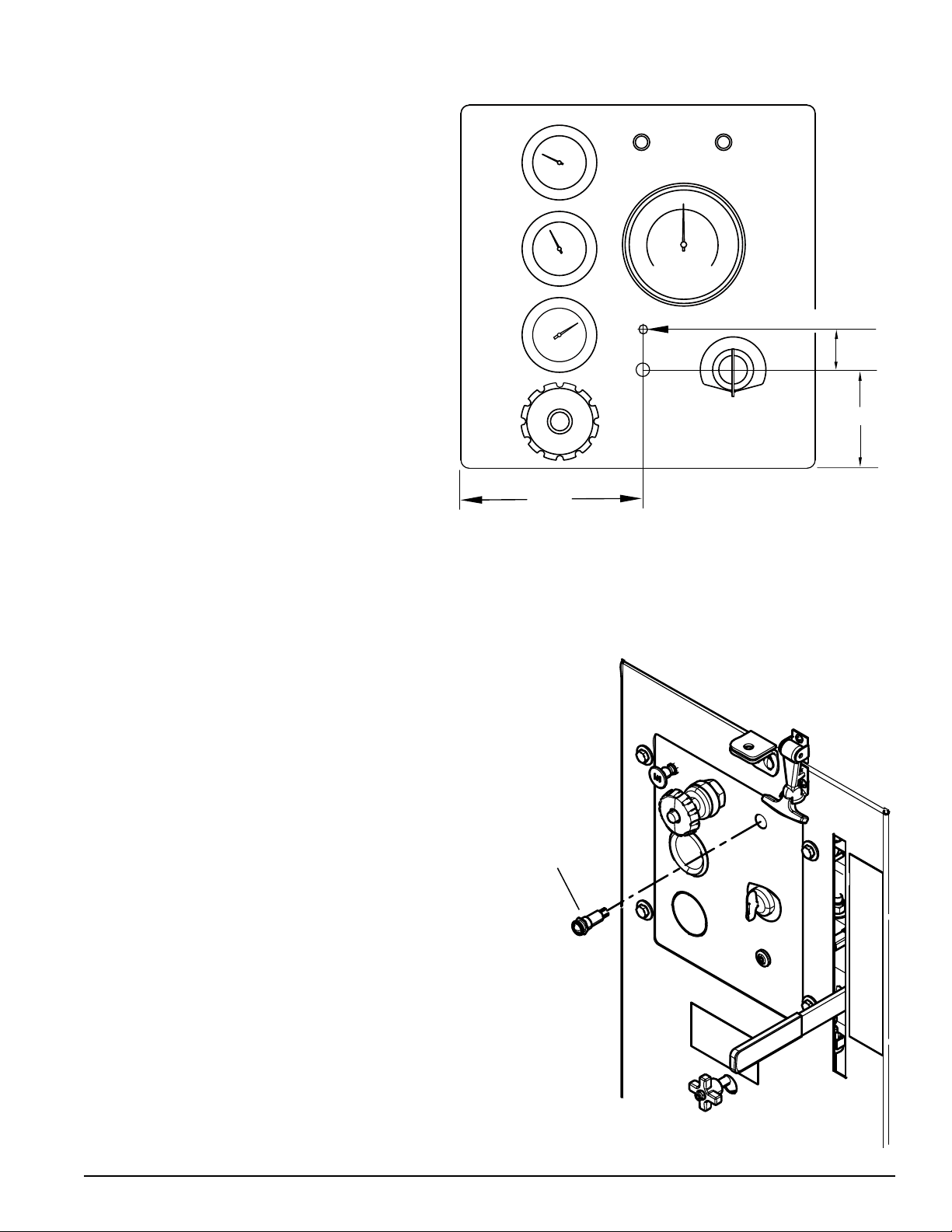
5. MOUNT THE TRI-COLOR LED
The Tri-Color LED mounts on the chipper control panel, which is located on the side of the chipper. Note that the
mounting location is different for the gas and diesel models. See Section 5.1 for gas engine models or 5.2 for diesel
engine models.
IMPORTANT
Take care not to damage the existing wiring when
drilling the hole for the LED!
5.1 - DRILL LOCATION FOR GAS ENGINE MODELS
Follow the measurements to drill a hole for the LED.
2
Instruction Sheet
Page 3
5.2 - DRILL LOCATION FOR DIESEL ENGINE MODELS
5.54"
3.00"
1.625
DRILL HOLE 9/16” IN DIAMETER
LED
Follow the measurements to drill a hole for the
LED. Drill the hole 1.625" above the Reset button
as shown.
6. INSERT THE TRI-COLOR LED
Install the tri-colored LED by unscrewing the LED hex
nut, pushing the LED into the control panel from the
front, and securing it with the hex nut from the back.
Instruction Sheet
3
Page 4

7. PLUG PLUS 1 CONTROLLER INTO MAIN HARNESS
PLUG INTO
PLUS 1
CONTROLLER
PLUG 2-PIN TO
2-PIN ON MAIN
HARNESS
PLUG 4-PIN TO
4-PIN ON MAIN
HARNESS
PLUG 6-PIN TO
6-PIN ON MAIN
HARNESS
TRIANGULAR END
(NOT USED)
CONNECT TO LED
EUROPEAN HARNESS
PLUG INTO
PLUS 1
CONTROLLER
DOMESTIC HARNESS
PLUG 4-PIN TO
4-PIN ON MAIN
HARNESS
PLUG 6-PIN TO
6-PIN ON MAIN
HARNESS
TRIANGULAR END
(NOT USED)
CONNECT TO LED
Note that the instructions for this step are different for European and Domestic machines. Choose the section below
that is correct for your machine.
DOMESTIC (US) MACHINES:
Unplug the main harness from the existing SmartRelay 1.
controller.
Locate the three connectors on the Plus 1 harness.2.
The connector with the triangular end is NOT USED.3.
Plug the 6-pin connector into the corresponding 6-pin 4.
connector on the main harness.
Plug the 4-pin connector into the 4-pin connector on 5.
the main harness.
There will be two 2-pin connectors left over on the main 6.
harness. Tape them together and out of the way.
Plug the two black and gray connectors on the other 7.
end of the Plus 1 harness to the corresponding
receptors on the Plus 1 controller.
EUROPEAN MACHINES:
Unplug the main harness from the existing SmartRelay 1.
controller.
Locate the four connectors on the Plus 1 harness.2.
The connector with the triangular end is NOT USED.3.
Plug the 6-pin connector into the corresponding 6-pin 4.
connector on the main harness.
Plug the 4-pin connector into the 4-pin connector on 5.
the main harness.
Plug the 2-pin connector into the red/black and light 6.
green 2-pin connector on the main harness.
There will be one 2-pin connector left over on the main 7.
harness. Tape it out of the way.
Plug the two black and gray connectors on the other 8.
end of the Plus 1 harness to the corresponding
receptors on the Plus 1 controller.
4
Instruction Sheet
Page 5

WHITE
BLUE
RED/YELLOW
8. HOOK UP THE LED
Connect the three wires on the Plus 1 harness to the LED as shown below.
If the wires are correctly connected, the light will flash red upon initial startup. If the light flashes green, the wires are
reversed. After initial startup, see Control Light Flash Codes chart for an explaination of all color codes.
9. OPERATION
Upon initial startup, make sure the chipper is in Neutral (Stop) position. If the chipper feed control is in any other 1.
position, the LED will flash red and forward feed will not be available.
Upon initial startup, if the chipper is in Neutral position, the LED will flash green, indicating that the RPM is not high 2.
enough to chip (see Optimal Rotor and Engine RPM chart).
Increase RPM gradually until the LED is solid green. Forward feed is now available.3.
See the Control Light Flash Codes table on the following page for a complete explaination of all flash codes provided 4.
by the LED. Save these instructions for future reference.
10. OPTIONAL REMOVAL OF SMARTRELAY
Once you have used the Plus 1 controller long enough to verify that it works correctly, the SmartRelay controller can be
removed along with the box that it is located in. A plate to cover the SmartRelay opening is provided with this kit, along
with the necessary hardware.
11. OPTIMAL ROTOR AND ENGINE RPM
Chipper Model Rotor RPM Engine RPM
CH611DH (76628) 1800 3000
CH6670H (76624) 1675 3780
CH6993H (76635) 1675 3780
OPTIMAL ROTOR AND ENGINE RPM
Instruction Sheet
5
Page 6

12. CONTROL LIGHT FLASH CODES
GUIDE TO THE CONTROLLER FLASH CODES
SIGNAL FREQUENCY CAUSE ACTION TO TAKE
GREEN
Green Solid light Forward feed available. Feed materials into the chute.
Green One flash per second
Red One flash per second
Red Solid light
RPM not high enough to chip
upon initial startup.
Disk RPM dropped while
chipping.
RED
Feed bar is not in STOP upon
initial startup.
RPM dropped too low for 10
seconds.
(CE compliant models only)
Light is solid red upon startup.
(CE compliant models only)
Safety bar was activated.
(Non-CE compliant models
only) Jumper harness plug
was damaged.
AMBER
Increase RPM gradually until the green light
stops flashing.
The feed roller will automatically reverse to
regulate the feed.
Put control bar in STOP position.
Put control bar in STOP position and then
reengage.
Push reset/override button to reset.
Check connections to jumper harness plug.
Replace if plug necessary (PN 36391-00)
Amber
Amber
Amber
On for 2 seconds and
then off for 2 seconds
Solid light for 7
seconds followed by a
long pause
On for 1/2 second,
then off for 1/2 second
for a period of 8
seconds followed by a
long pause
Check the sharpness of the
chipper blades.
There is a short or open circuit
in the forward feed.
There is a short or open circuit
in the reverse feed.
Check sharpness of chipper blades. Sharpen
or flip if necessary.
To reset the controller: With the control bar
in STOP, turn the keyswitch to ON, and then
shift the control bar from reverse to reverse
and back three times within 60 seconds.
Check connections to the forward coil on the
feed hydraulic valve. Replace coil if necessary.
Check connections to the reverse coil on the
feed hydraulic valve. Replace coil if necessary.
6
Instruction Sheet
Page 7

12
1
2
3
4
5
6
7
8
9
10
11
4
PLUS 1 CONTROLLER KITS, PN 76170-00 AND 76171-00
ITEM PART NUMBER DESCRIPTION QTY
1 15238 BOLT, 1/4 X 3/4 CRG 2
2 75977-12 PLATE, CONTROLLER 1
3 36261-00 BUMPER, 1” OD WITH 1/4” STUD 4
4 15355 NUT, 1/4 NYLOCK 6
5 36258-00 CONTROLLER, PLUS 1 CHIPPER 1
6 15214 BOLT, 1/4 X 1-1/4 G5 ZP HCS 2
7 15197 BOLT, 1/4 X 2-1/4 HEX HD 2
8 75978-12 PLATE, COVER 1
9 15367 BOLT, 5/16 X 3/4 CRG 2
10 15356 NUT, 5/16 NYLOCK 2
11 15030 WASHER, 1/4 FLAT 2
12 36356-00 LED, TRI-COLOR 12V 3-TERM BASE 1
36381-00 HARNESS, 6” PLUS 1 (GAS EUROPEAN) 1
36383-00 HARNESS, 6” PLUS 1 (DIESEL EUROPEAN) 1
36397-00 HARNESS, 6” PLUS 1 (GAS DOMESTIC) 1
36398-00 HARNESS, 6” PLUS 1 (DIESEL DOMESTIC) 1
Instruction Sheet
7
Page 8

ECHO BEAR CAT
www.bearcatproducts.com
237 NW 12th Street, West Fargo, ND 58078-0849
Phone: 701.282.5520 • Toll Free: 800.247.7335 • Fax: 701.282.9522
E-mail: service@bearcatproducts.com • sales@bearcatproducts.com
 Loading...