

Page 1
Instructions
SUBJECT: PLUS+1
RE-PROGRAMMING KIT #77370-00
™
CONTROLLER
Before inspecting or servicing any part of this machine,
shut off power source, remove key, disconnect the
battery cables and make sure all moving parts have
come to a complete stop.
WARNING
MODELS: HYDRAULIC FEED MOD-
ELS WITH PLUS
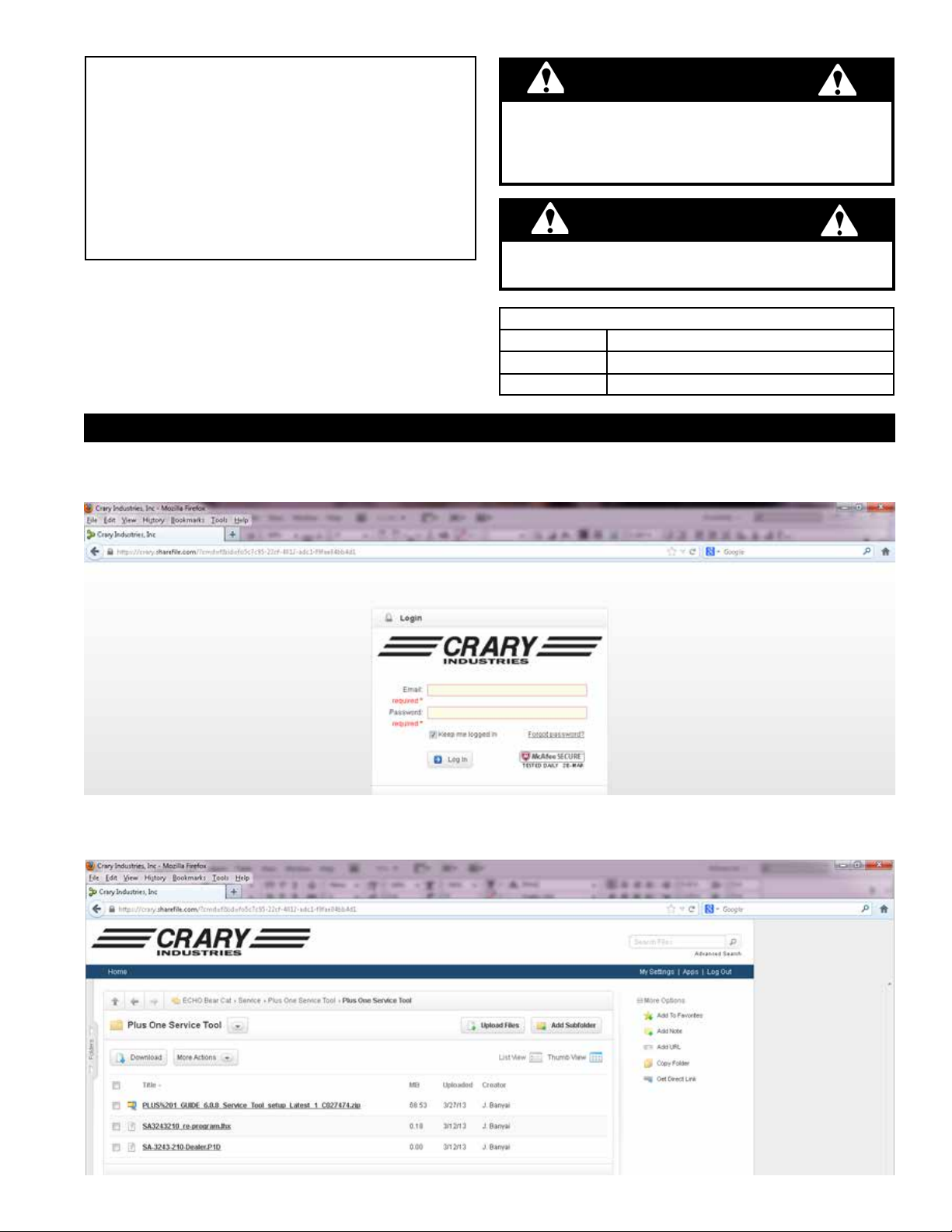
1. SECTION 1: LOGIN AND DOWNLOADING FILES FOR SOFTWARE
1. To install the software drivers contact service@bearcatproducts.com to recieve a link to a site login. Enter the
username and the password sent with the link.
™
+1
CONTROLLER
The reprogramming software requires a PC computer
with Microsoft Windows based operating system.
Part # Description
36503-00
77369-00 INSTRUCTIONS, PLUS ONE SERVICE TOOL
IMPORTANT
KIT, PLUS+1™ SERVICE TOOL, 77370-00
CABLE, PLUS
™
+1
PROGRAMMING
2. Once you have logged in enter folder "Plus One Service Tool."
3. Double click file "PLUS%201_GUIDE_6.0.8_Service_Tool_setup_Latest_1_C027474.zip"
PN 77369-00
Rev. 041513
Page 2
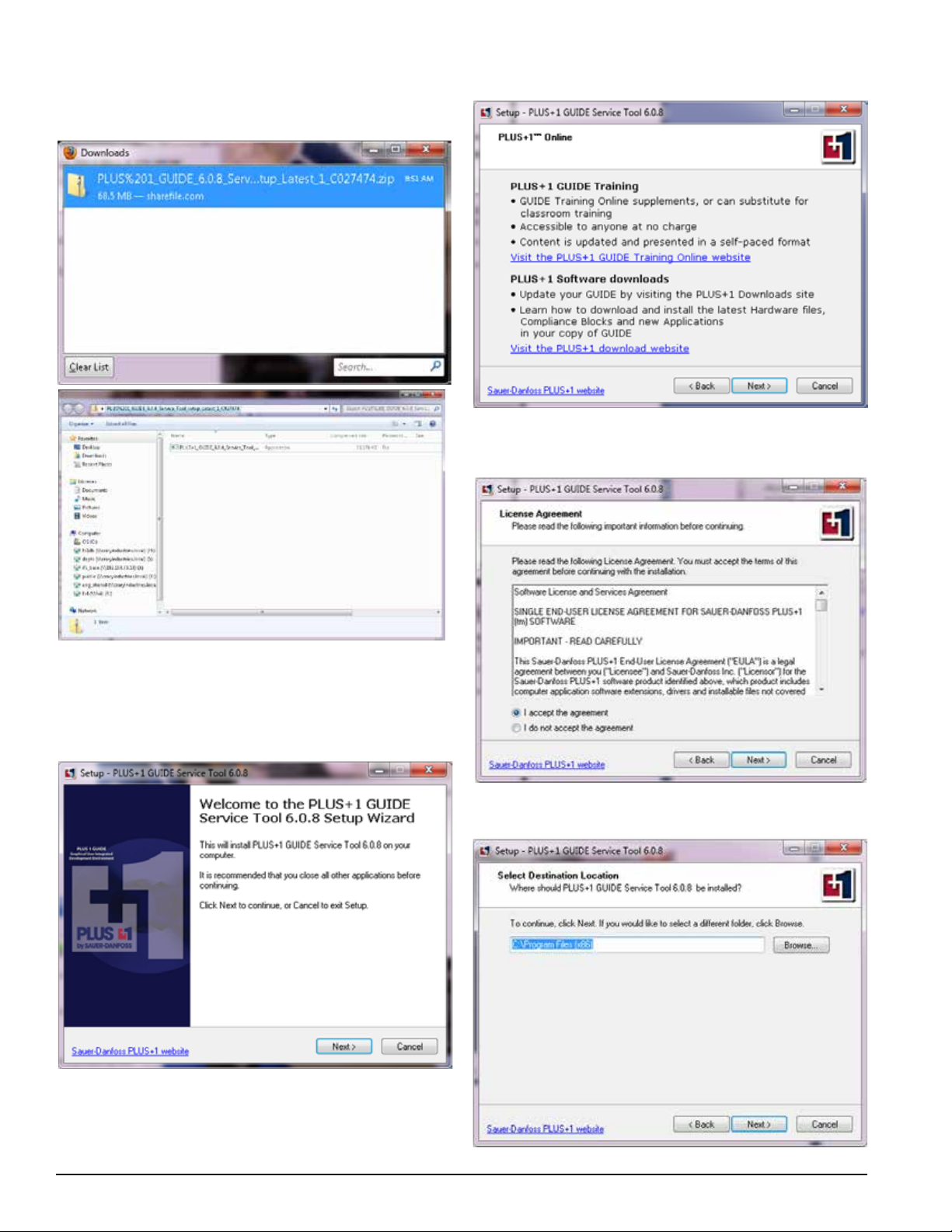
4. Save the file and open up the ZIP folder in your
Downloads. Double click the file inside to open the
prompting dialog.
7. Dialog Box 2: Click the "Next" button.
8. Dialog Box 3: Be sure to click the "I accept the
agreement" icon and then click the 'Next' button.
5. A series of dialog boxes will begin to appear. Follow
the instructions on each dialog box until installation is
complete. The series of dialog boxes are detailed below.
6. Dialog box 1: Click the "Next" button.
9. Dialog Box 4: Choose folder and click the 'Next' button.
2
Instruction Sheet
Page 3
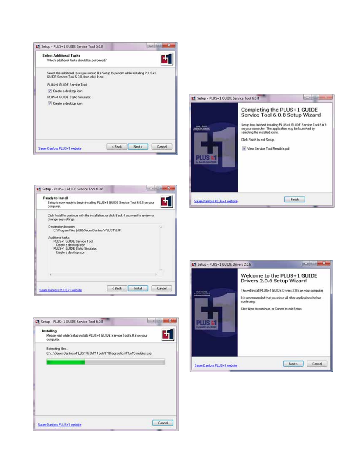
10. Dialog Box 5: Leave the boxes checked. Click the
'Next' button.
11. Dialog Box 6: This box reviews your desired locations.
Click the 'Install' button to begin installation.
13. Dialog Box 8: When the Downloading is complete the
downloading bar will disappear. Click the 'Finish' button
to complete Service Tool setup.
12. Dialog Box 7: Downloading bar will appear.
If the drivers have never been installed on your computer,
the next series of dialog boxes will begin. Follow the
instructions through to complete installation.
1. Dialog Box 9: Click the "Next" button.
Instruction Sheet
3
Page 4
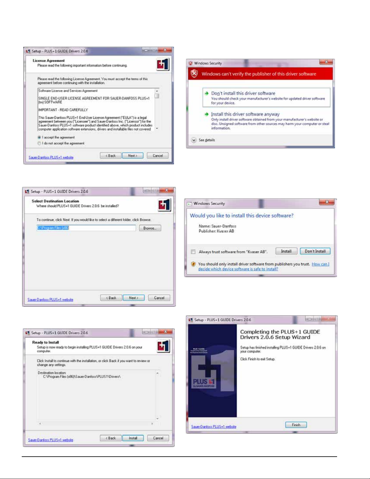
2. Dialog Box 10: Be sure to click the "I accept the
agreement" icon and then click the 'Next' button.
3. Dialog Box 11: Click the 'Next' button.
5. Dialog Box 13: This box is a Security Warning box that
may appear, depending on the type of security software
installed on your computer. Click the 'Install this driver
software anyway' button to continue.
6. Dialog Box 14: This is also a Security Warning box that
may appear, depending on the type of security software
installed on your computer. Click the 'install' button to
continue. (Note: It is not necessary to click the 'Always
trust software from "Kvaser AB"' box).
4. Dialog Box 12: Choose folder and click the 'Next' button.
4
Instruction Sheet
7. Dialog Box 15: This is the nal dialog box that should
appear for the installation. Click the 'Finish' button to
complete.
Page 5
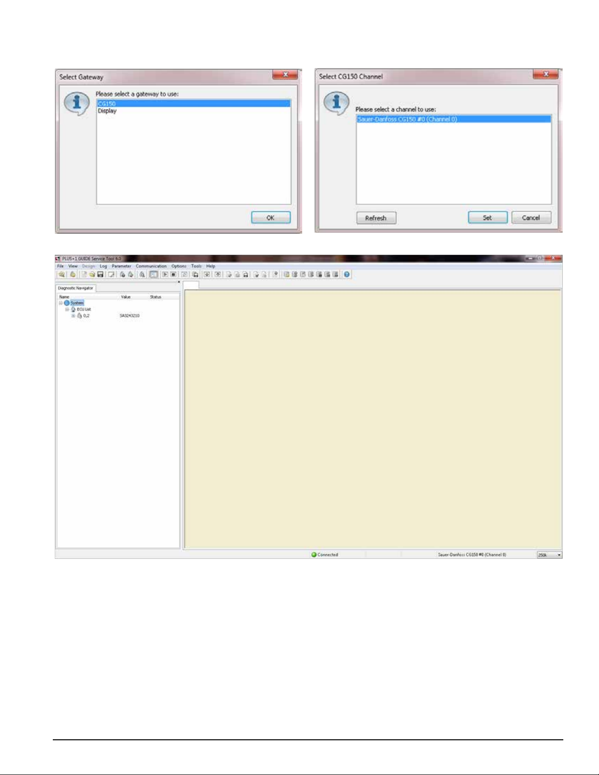
8. Dialog Box 16: Highlight "CG150" and click the "OK"
button.
9. Dialog Box 17: Selet channel shown and click the "Set"
button.
10. The main screen detailed below indicates that the drivers are installed.
11. Once the drivers are installed, you will need to download the diagnostic data files from the "Plus One Service Tool."
12. It is now necessary to connect the Communications Cable provided in kit from the computer to the controller port.
SEE PAGE 8 FOR DETAILS. Next, supply a good source of 12 volt power to the controller. You'll know if it's properly
powered if the controller's indicator light turns on or begins to flash.
13. The Communication Cable MUST BE CONNECTED in order to move forward.
Instruction Sheet
5
Page 6
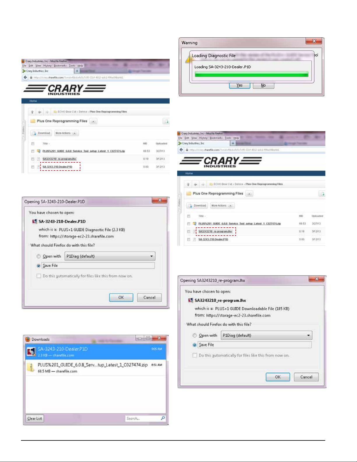
14. Return to "Plus One Service Tool" and download
"SA3243210_re-program.lhx" and "SA-3243-210Dealer.P1D."
15. Double click "SA-3243-210-Dealer.P1D."
16. Dialog Box 1a: Select "Save File" and click the "OK"
button.
18. DIalog Box 2a: The le will upload, then click "Yes."
19. The le will bring you back to the main screen. Then go
back to the "Plus One Service Tool" and double click
"SA3243210_re-program.lhx."
17. The le will save into your Downloads. Double click
to open.
20. Dialog Box 1b: Select "Save File" and click the "OK"
button.
6
Instruction Sheet
Page 7
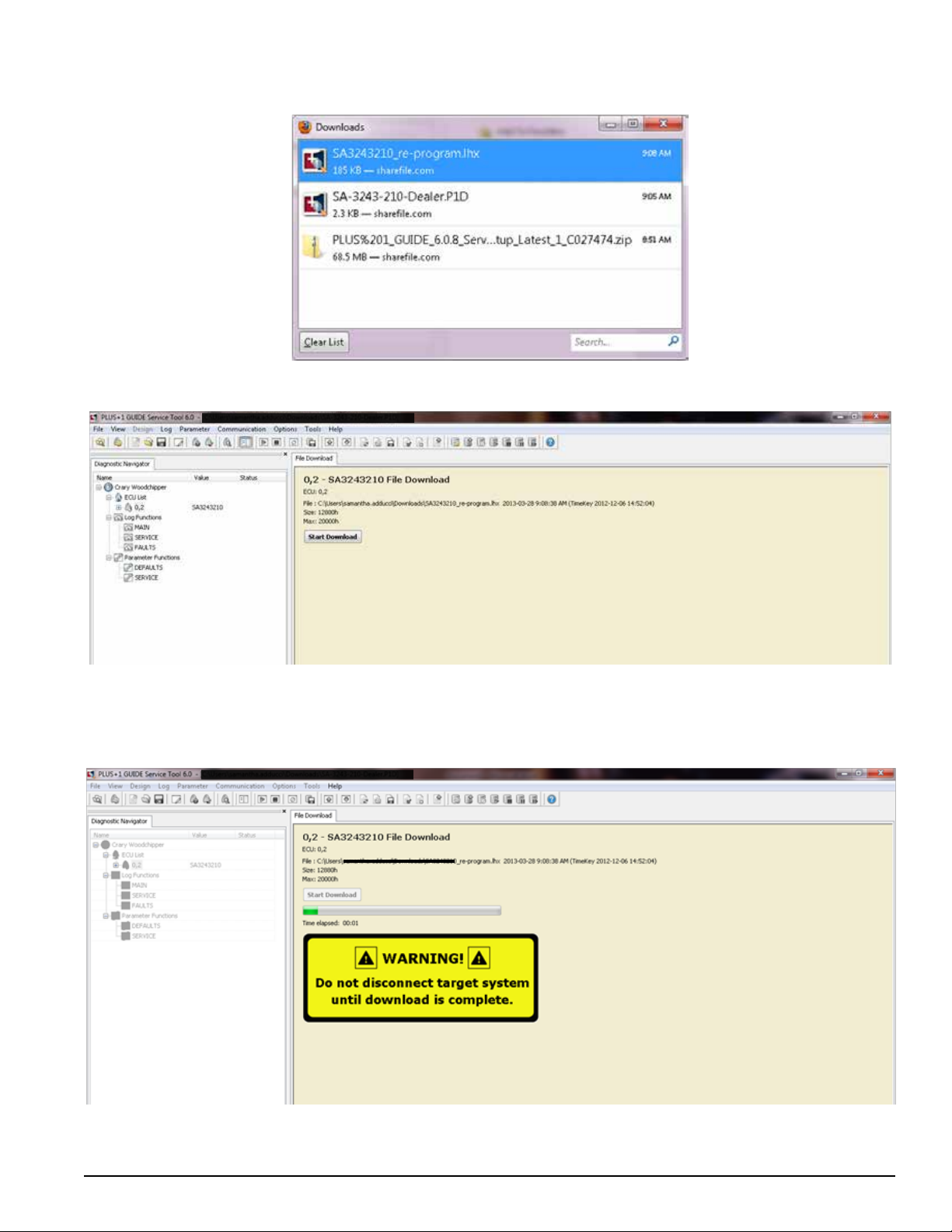
21. The le will save into your Downloads. Double click
to open.
22. The main screen below will appear. Click the "Start Download" button.
23. After the download has completed successfully, you'll see the program appear in the Diagnostics Navigator as
pictured below. The yellow WARNING box will disappear after downloading is complete.
24. At this point, the Plus One Controller has been updated to the most current revision.
Instruction Sheet
7
Page 8
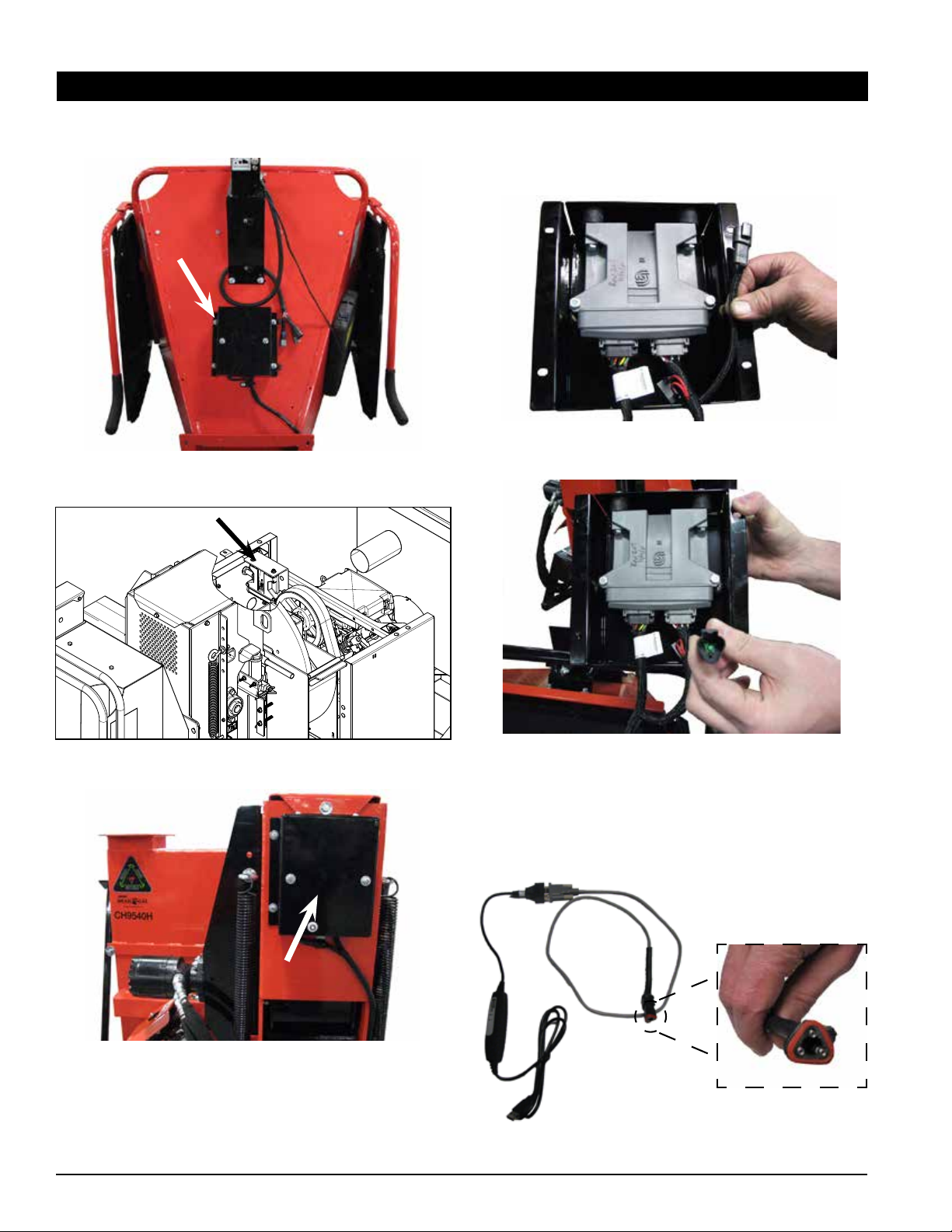
2. SECTION 2: CONNECT TO CONTROLLER
1. Locate the Plus One Controller on your machine.
Controller location on 6" models with VIN
5VJAA00148W001215 and above.
2. Remove the cover to the controller box and locate the
programming wire. It has a triangular shaped connector
and should be tucked in along side the controller.
Triangular programming wire will be tucked in along the control-
ler in the box.
Controller location on 6" models with VIN
5VJAA00178W001144 and below.
Controller location on CH9540H, CHF9540H, CH8670H,
CH8993H, CH8720iH, CH922DH & CH911DH models.
8
3. Locate the programming cable (36503-00) supplied in
the service tool kit and connect the triangular shaped
plug to the programming wired located in the controller
box.
4. Plug the other end of the programming cable into a
USB port on the computer being used.
PROGRAMMING CABLE, 36503-00
Instruction Sheet
Page 9

THIS PAGE INTENTIONALLY LEFT BLANK
Instruction Sheet
9
Page 10
SEE PAGES 12
& 13 FOR CLICK
THROUGH
INSTRUCTIONS
ON THIS SCREEN
CLICK TWO
CLICK THREE
CLICK ONE
CLICK SIX
10
Instruction Sheet
Page 11

CLICK SEVEN
CLICK FOUR
CLICK FIVE
CLICK EIGHT
Instruction Sheet
11
Page 12

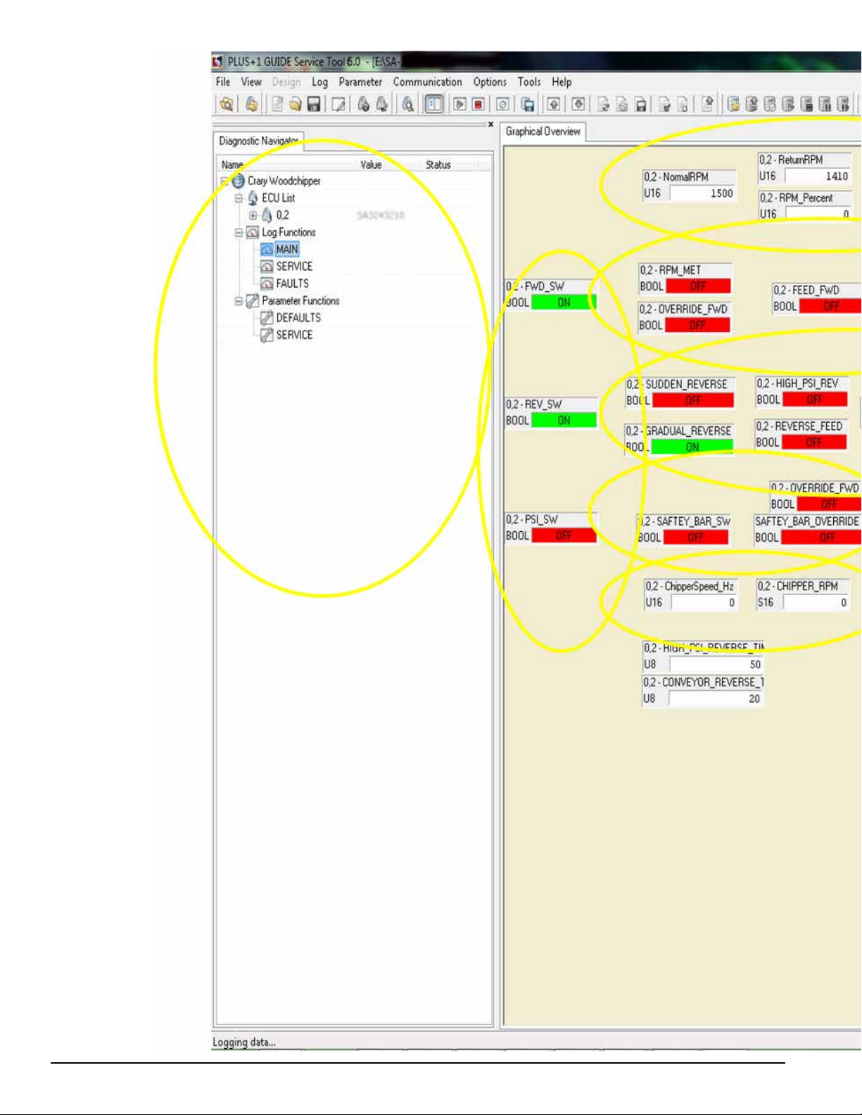
CLICK ONE - (ON LEFT SIDE NAVIGATION BAR)
In this yellow circle are the screens you can click on once entered into the service tool for
troubleshooting. You can see in this slide I am in the heading called MAIN in the navigator under
Log Functions.
All the Green or Red boxes will change color Red(Off) and Green(ON) when the machine has
seen this function on the controller.
CLICK TWO -
The Normal RPM is the RPM setting the forward feed will turn on at on this model it was set at
1500.
The Return RPM is when the disc will turn on the forward feed after the RPM has dropped to the
sudden low or gradual low. This model is set at 1410 RPM.
The Gradual low RPM (This is when a log being feed in slowly brings down the RPM. On this
CH8720IH the forward feed will shut off at this 1200RPM.)
Sudden Low and RPM percent will not populate in the service tool until the engine and disc have
been engaged
CLICK THREE -
The top box labeled FWD_SW is your forward switch or forward sensor in the control box on the
hopper.
The second box is your reverse sensor on top of the hopper or switch this is labeled REV_SW.
The third is the pressure switch on top of the 18527-00 DO3 valve assembly.
CLICK FOUR -
The box labeled RPM_MET will tell you the disc has met the normal operating speed setting on
this machine it will be 1500)
(For CE Compliant machines) The box labeled Override_FWD is when the safety bar switch
has been pushed or activated and then has been overridden by pushing and holding the CE
safety bar override switch on the back of the control box on the hopper for up to 5 seconds.
12
Instruction Sheet
Page 13

The box labeled Feed_FWD is when the forward solenoid on the 18527-00 DO3 valve assembly
has been powered or activated
The box labeled FWD_FAULT is when the controller has detected a problem with the forward coil
or the wiring up to this coil.
CLICK FIVE -
SUDDEN_REVERSE is when the RPM has dropped suddenly at the disc.
GRADUAL_REVERSE is when the disc has dropped gradually
HIGH_PSI_REV is when the hydraulic system sees high pressure due to a jam at the feed roller
this will activate the REVERSE_FEED box below for 1 second.
FEED_REV is when the feed roller is traveling in the reverse direction after the PSI _Switch has
been activated.
The box labeled REV_FAULT is when the controller has detected a problem with the reverse coil
or the wiring up to this coil.
CLICK SIX -
Safety_Bar_Sw is when the safety bar has been activated or tripped.
(For CE Compliant machines) Safety_BAR_OVERIDE is when the CE safety bar override
switch has been pushed to deactivate the safety bar switch.
CLICK SEVEN -
Chipperspeed_HZ will tell you what the disc is traveling in hertz
Chipper_RPM will tell you what the disc is traveling in RPM.
CLICK EIGHT -
CP_Green_Flash -will tell you when the tri-color LED is flashing Green
CP_Green_ON will tell you when the Green is solid at the tri-color light
Instruction Sheet
13
Page 14

CLICK ONE - (ON LEFT SIDE
NAVIGATION BAR)
We have now moved to the
SERVICE tab on the left.
CLICK TWO -
CP_EngHrResetCount is how
many times the code for changing
the oil has been reset. This will
only be relevant on controllers with
the REV207 and older. We have
removed the oil change code to
simplify the codes.
CP_EngHRReset_3 is when the
control bar has successfully reset
the engine oil reset.
CP_EnghrResetINEnable this
will turn on within the time frame
you have to reset the time on the
engine oil code.
CP_model (This tab is not
available on the dealer or
distributor version).
CLICK THREE-
Blade_Run_Minutes is the time
(in minutes) the sensor at the disc
has seen RPM.
Blade_Run_Hours is the time (in
Hours) the sensor at the disc has
seen RPM.
Engine_Run_Minutes is the time
(in minutes) the key switch has
been turned on.
Engine_Run_Hours is the time
(in Hours) the key switch has been
turned on.
CLICK ONE
CLICK FOUR-
These boxes are not used at this
time.
14
Instruction Sheet
Page 15

CLICK TWO
CLICK THREE
CLICK FOUR
Instruction Sheet
15
Page 16

CLICK ONE- (ON LEFT SIDE
NAVIGATION BAR)
We have now moved to the
FAULTS tab on the left.
The box labeled FWD_FAULT is
when the controller has detected
a problem with the forward coil or
the wiring up to this coil.
The box labeled REV_FAULT is
when the controller has detected
a problem with the reverse coil or
the wiring up to this coil.
The other three grey boxes are
used by the manufacturer of the
controller.
CLICK ONE
CLICK TWO
16
Instruction Sheet
Page 17

Instruction Sheet
17
Page 18

CLICK ONE- (ON LEFT SIDE
NAVIGATION BAR)
We have now moved to the
DEFAULTS tab on the left
under Parameter Functions
this is just the default password
18
Instruction Sheet
Page 19

Instruction Sheet
19
Page 20

CLICK ONE- (ON LEFT SIDE
NAVIGATION BAR)
We have now moved to the
Service tab on the left under
Parameter Functions.
CLICK TWO-
Blade_Run_Minutes is the time
(in minutes) the sensor at the disc
has seen RPM.
Blade_Run_Hours is the time (in
Hours) the sensor at the disc has
seen RPM.
Engine_Run_Minutes is the time
(in minutes) the key switch has
been turn on.
Engine_Run_Hours is the time
(in Hours) the key switch has been
turn on.
CLICK ONE
Service_set_Value is not on
the dealer version and has been
replaced by a box called FR_
Swdelay_Ms-this box should not
be adjusted on the dealer version.
CLICK TWO
20
Instruction Sheet
Page 21
Instruction Sheet
21
Page 22

Page 23

Page 24

ECHO BEAR CAT
www.bearcatproducts.com
237 NW 12th Street, West Fargo, ND 58078-0849
Phone: 701.282.5520 • Toll Free: 800.247.7335 • Fax: 701.282.9522
E-mail: service@bearcatproducts.com • sales@bearcatproducts.com
 Loading...