

Page 1
Instructions
SUBJECT: SAFETY SWITCH
REPLACEMENT ON CE COMPLIANT
CHIPPERS WITH HYDRAULIC FEED
AND SAFETY KNEE BAR SYSTEM
WARNING
Before inspecting or servicing any part of this machine,
shut off power source, disconnect spark plug wire from
spark plug and make sure all moving parts have come
to a complete stop.
SWITCH BOX INSTALLATION
MODELS:
CH5540HXE - KIT #77540-00
CH6730HXE - KIT #77542-00
CH611DHXE, CH6993HXE &
CH6670HXE, CH8670HXE CH8993HXE,
CH8720IHXE, CH911DHXE & CH922DHXE, CH9540HXE - KIT # 77536-00
KIT #77542-00 FOR MODELS: CH6730HXE
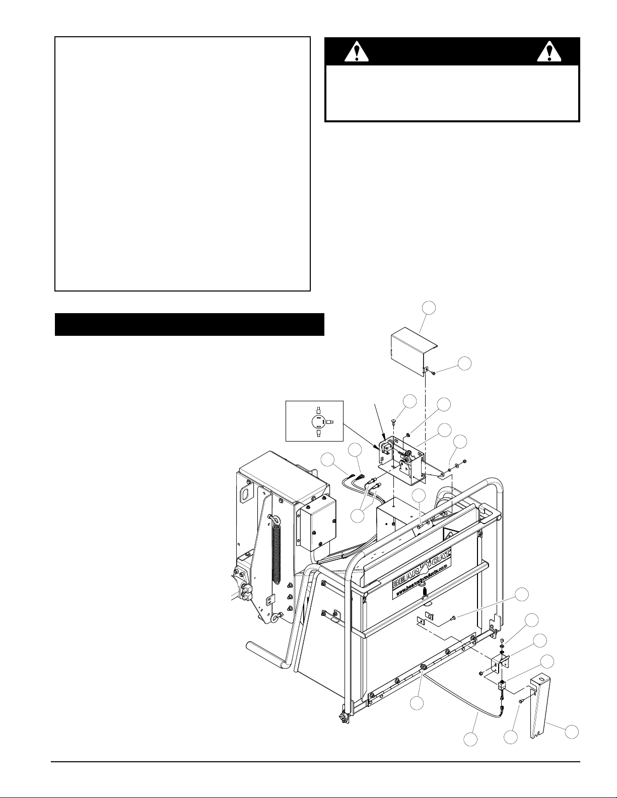
SWITCH BOX REMOVAL
1. Remove control box cover
(2) by removing four serrated
ange bolts (3).
2. Remove proximity sensors
(4) by removing inside nut
(5) closest to the control arm.
Note from which position
each sensor came from
they will need to be installed
in the same holes during
installation of new control
box.
TRI-COLOR LED
RED/YEL
RED/GRN
1. Mount new switch box (1) to switch box
mount with two carriage bolts (10), washers,
and nuts. Ensure switch box is all the to
the front of the machine in the slot before
tightening completely
2. Connect control arm to switch control bar
using bolt (8), spacer, washer, and nut.
Ensure spacer (9) is in the switch control
bar before tightening.
2
3
COMPLETE
CIRCUIT
WHT
7
6
4
10
5
1
9
8
3. Remove wires from the back
of the reset switch (6) and
Tri-Color LED (7). Remove
Tri-Color LED from control
box. (7)
4. Remove Bolt (8) connecting
control arm to switch control
bar.
5. Remove two carriage bolt
(10) connecting switch box
(1) to switch box mount.
3
CH6730HXE Chipper Chute
8
5
6
4
7
2
Rev. 032913
1
77541-00
Page 2
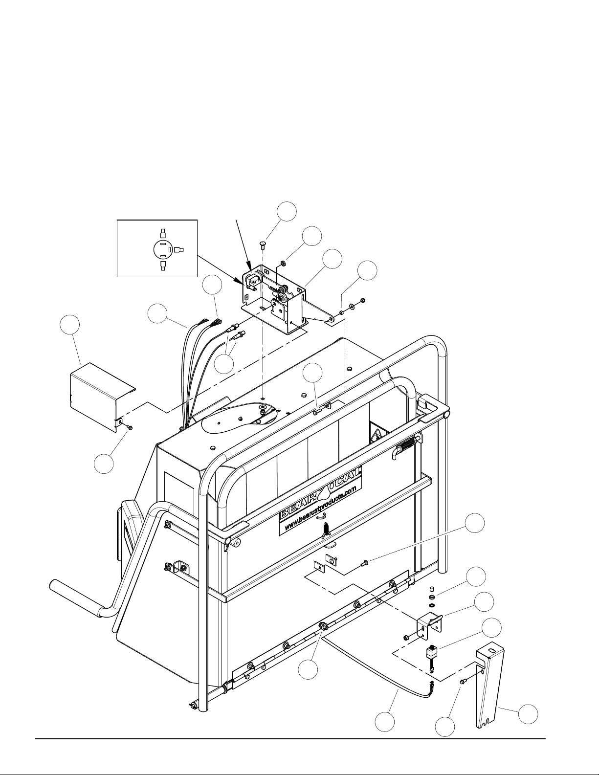
3. Install Tri-Color LED into control box so that the silver terminal is located at the three o'clock
position from the inside of the box.
4. Connect wires to the back of the reset switch (6) and Tri-Color LED (7). Ensure wires for the
Tri-Color LED are connected as shown in diagram.
5. Install proximity sensors (4) into control box (1) using the nuts (5) previously removed. Ensure
that sensors are put into the same hole that they came out of and that there is a 1/32” gap
between the sensor and switch control bar. Ensure not to overtighten damage to sensor may
occur.
6. Install control box cover (2) on control box (1) using four serrated ange bolts (3).
2
TRI-COLOR LED
RED/YEL
RED/GRN
6
3
WHT
COMPLETE
CIRCUIT
7
4
10
5
1
9
8
CH6670HXE and CH6993HXE Chipper Chute
Instruction Sheet
3
7
8
5
6
4
1
2
Page 3
COMPLETE
CIRCUIT
WHT
RED/YEL
RED/GRN
TRI-COLOR LED
8
1
2
3
4
5
6
7
8
9
10
5
6
4
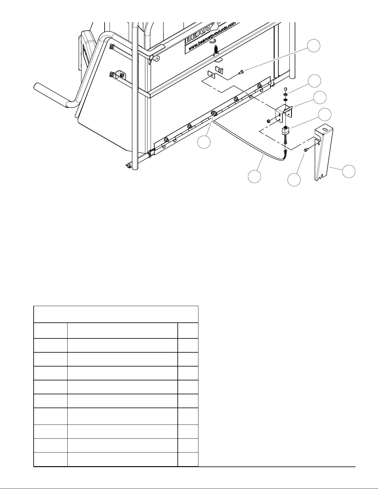
KNEE BAR SWITCH REMOVAL
1. Remove the two screws (2) and loosen the
nut (3) at the bottom of the knee bar switch
cover (1) and remove it.
2. Remove plunger switch (4) from switch
bracket by removing plunger nut.
Disconnect plunger switch from harness
(7) by removing the two screws connecting
them
3. Remove switch bracket (6) from extension
tray by removing two carriage bolts (8).
14624-00 CONNECTOR, 1/4 QD FEMALE 2
KIT, CONTROL SWITCHES (CH6730HXE)
PART# DESCRIPTION QTY
Part #77542-00
3
PLUNGER SWITCH INSTALLATION
1. Install new switch bracket (6) on to
extension tray using two carriage bolts (8).
2. Install new plunger switch (4) into switch
bracket using supplied plunger nut (5),
washer, and plunger.
3. Cut off ring terminals from plunger end
of harness (7) and replace with supplied
female spade connectors. Connect
harness to plunger switch (4).
4. Using two screws (2) mount the new
switch cover (1) to switch bracket(6).
While installing adjust the new switch
cover so that it prevents the plunger switch
from bottoming out when the knee bar is
depressed.
7
2
1
14625-00 CONNECTOR, 1/4 QD MALE 2
15176 SCW,11/32*7/8 HWH AB THREAD ZP 2
15349 BOLT,CARR 5/16*7/8" GR5 NC ZP 2
15904-00 NUT, 5/16-18 NYLOCK-FLANGE 2
32375-00
77527-00 ASSEMBLY, SWITCH BOX 1
77532-12 BRACKET, SWITCH 1
77535-12 SHIELD, SAFETYBAR SWITCH 1
SWITCH, MOMENTARY IP67 NORMALLY ON
Instruction Sheet
5. Adjust plunger switch (4) by loosening
the two carriage bolts (8) and setting it so
that it is activated when the knee bar is
depressed.
1
Page 4

COMPLETE
10
KIT #77536-00 FOR MODELS: CH611DHXE, CH6993HXE & CH6670HXE
CH8993HXE,CH8720IHXE, CH8670HXE, CH911DHXE, CH922DHXE
SWITCH BOX REMOVAL
1. Remove control box cover (2) by removing four serrated ange bolts (3).
2. Remove proximity sensors (4) by removing inside nut (5) closest to the control arm. Note from
which position each sensor came from they will need to be installed in the same holes during
installation of new control box.
3. Remove wires from the back of the reset switch (6) and Tri-Color LED (7). Remove Tri-Color
LED from control box. (7)
4. Remove Bolt (8) connecting control arm to switch control bar.
5. Remove two carriage bolt (10) connecting switch box (1) to chipper chute.
TRI-COLOR LED
RED/YEL
RED/GRN
WHT
CIRCUIT
5
1
9
7
6
2
4
8
3
8
CH611DHXE Chipper Chute
5
6
4
3
7
2
1
Page 5

SWITCH BOX INSTALLATION
1. Mount new switch box (1) to top of chipper
chute with two carriage bolts (10), washers,
and nuts. Ensure switch box is all the to
the front of the machine in the slot before
tightening completely
2. Connect control arm to switch control bar
using bolt (8), spacer, washer, and nut.
Ensure spacer (9) is in the switch control bar
before tightening.
3. Install Tri-Color LED into control box so that
the silver terminal is located at the three
o'clock position from the inside of the box.
4. Connect wires to the back of the reset switch
(6) and Tri-Color LED (7). Ensure wires for
the Tri-Color LED are connected as shown in
diagram.
TRI-COLOR LED
RED/YEL
WHT
COMPLETE
CIRCUIT
5. Install proximity sensors (4) into control box
(1) using the nuts (5) previously removed.
Ensure that sensors are put into the same
hole that they came out of and that there
is a 1/32” gap between the sensor and
switch control bar. Ensure not to overtighten
damage to sensor may occur.
6. Install control box cover (2) on control box (1)
using four serrated ange bolts (3).
2
3
10
5
RED/GRN
1
9
7
6
8
4
8
5
6
4
3
CH8720iHXE, CH8993HXE, CH911DHXE, CH922DHXE & CH9540H Chipper Chute
Instruction Sheet
7
2
1
Page 6

COMPLETE
CIRCUIT
WHT
RED/YEL
RED/GRN
TRI-COLOR LED
8
1
2
3
4
5
6
7
8
9
10
5
6
4
KNEE BAR SWITCH REMOVAL
1. Remove the two screws (2) and loosen the
nut (3) at the bottom of the knee bar switch
cover (1) and remove it.
2. Remove plunger switch (4) from switch
bracket by removing plunger nut.
Disconnect plunger switch from harness
(7) by removing the two screws connecting
them
3. Remove switch bracket (6) from extension
tray by removing two carriage bolts (8).
KIT, CONTROL SWITCHES, Part #77536-00
PART# DESCRIPTION QTY
14624-00 CONNECTOR, 1/4 QD FEMALE 2
3
PLUNGER SWITCH INSTALLATION
1. Install new switch bracket (6) on to
extension tray using two carriage bolts
(8).
2. Install new plunger switch (4) into
switch bracket using supplied plunger
nut (5), washer, and plunger.
3. Cut off ring terminals from plunger end
of harness (7) and replace with supplied
female spade connectors. Connect
harness to plunger switch (4).
4. Using two screws (2) mount the new
switch cover (1) to switch bracket(6).
While installing adjust the new switch
cover so that it prevents the plunger
switch from bottoming out when the
knee bar is depressed.
7
2
1
14625-00 CONNECTOR, 1/4 QD MALE 2
15176 SCW,11/32*7/8 HWH AB THREAD ZP 2
15349 BOLT,CARR 5/16*7/8" GR5 NC ZP 2
15904-00 NUT, 5/16-18 NYLOCK-FLANGE 2
32375-00
77527-00 ASSEMBLY, SWITCH BOX 1
77532-12 BRACKET, SWITCH 1
SWITCH, MOMENTARY IP67 NORMALLY ON
Instruction Sheet
5. Adjust plunger switch (4) by loosening
the two carriage bolts (8) and setting
it so that it is activated when the knee
bar is depressed.
1
Page 7

KIT # 77540-00 FOR MODEL: CH5540HXE
2
TRI-COLOR LED
RED/YEL
RED/GRN
WHT
COMPLETE
CIRCUIT
4
6
7
10
3
5
1
9
8
SWITCH BOX INSTALLATION
1. Mount new switch box (1)
to top of chipper chute
with two hex bolts (10),
washers, and nuts. Ensure
switch box is all the to the
front of the machine in
the slot before tightening
completely
2. Connect control arm to
switch control bar using
bolt (8), spacer, washer,
and nut. Ensure spacer (9)
is in the switch control bar
before tightening.
3. Install Tri-Color LED into
control box so that the
silver terminal is located at
the three o'clock position
from the inside of the box.
SWITCH BOX REMOVAL
1. Remove control box cover (2) by removing
serrated ange bolts (3).
2. Remove mechanical switches (4) by
removing inside nut (5) closest to the control
arm. Note from which position each switch
came from they will need to be installed in
the same holes during installation of new
control box.
3. Remove wires from the back of the reset
switch (7) and Tri-Color LED (6).
4. Remove Bolt (8) connecting control arm to
switch control bar.
5. Remove two hex bolt (10) connecting switch
box (1) to chipper chute.
Instruction Sheet
6. Connect wires to the back of the reset switch
(7) and Tri-Color LED (6). Ensure wires for
the Tri-Color LED are connected as shown in
diagram.
7. Install mechanical switches (4) into control
box (1) using the nuts (5) previously
removed. Ensure that switches are put into
the same hole that they came out of. Ensure
not to overtighten damage to switch may
occur.
8. Install control box cover (2) on control box (1)
using serrated ange bolts (3).
Page 8

COMPLETE
CIRCUIT
WHT
RED/YEL
RED/GRN
TRI-COLOR LED
8
1
2
3
4
5
6
7
8
9
10
5
6
4
KNEE BAR SWITCH REMOVAL
1. Remove the two screws (2) and loosen the
nut (3) at the bottom of the knee bar switch
cover (1) and remove it.
2. Remove plunger switch (4) from switch
bracket by removing plunger nut.
Disconnect plunger switch from harness
(7) by removing the two screws connecting
them
3. Remove switch bracket (6) from extension
tray by removing two carriage bolts (8).
PART# DESCRIPTION QTY
14624-00 CONNECTOR, 1/4 QD FEMALE 2
14625-00 CONNECTOR, 1/4 QD MALE 2
15176 SCW,11/32*7/8 HWH AB THREAD ZP 2
15349 BOLT,CARR 5/16*7/8" GR5 NC ZP 2
15904-00 NUT, 5/16-18 NYLOCK-FLANGE 2
32375-00
KIT, CONTROL SWITCHES (5 INCH)
Part #77540-00
SWITCH, MOMENTARY IP67 NORMALLY ON
3
1
PLUNGER SWITCH INSTALLATION
1. Install new switch bracket (6) on to
extension tray using two carriage
bolts (8).
2. Install new plunger switch (4) into
switch bracket using supplied plunger
nut (5), washer, and plunger.
3. Cut off ring terminals from plunger
end of harness (7) and replace with
supplied female spade connectors.
Connect harness to plunger switch
(4).
4. Using two screws (2) mount switch
cover (1) to switch bracket(6). While
installing adjust the switch cover so
that it is prevents plunger switch from
bottoming out when the knee bar is
depressed.
5. Adjust plunger switch (4) by loosening
the two carriage bolts (8) and setting
it so that it is activated when the
knee bar is depressed.
1
7
2
77530-00 ASSEMBLY, SWITCH BOX 1
77532-12 BRACKET, SWITCH 1
77534-12 SHIELD, SAFETY BAR SWITCH 1
ECHO BEAR CAT
Phone: 701.282.5520 • Toll Free: 800.247.7335 • Fax: 701.282.9522
E-mail: service@bearcatproducts.com • sales@bearcatproducts.com
237 NW 12th Street, West Fargo, ND 58078-0849
www.bearcatproducts.com
 Loading...