

Page 1

5 INCH CHIPPER
CH5540H - 540 PTO HYDRAULIC FEED
ENGLISH ESPAÑOL FRANÇAIS
PN: 12666
Rev. 010113
Companion to 12665
SN Range: D00001 to Current
OWNER'S MANUAL
Page 2

Before You Begin
DEAR ECHO BEAR CAT CUSTOMER
Thank you for purchasing a ECHO Bear Cat product. The ECHO Bear Cat line is designed, tested, and manufactured
to give years of dependable performance. To keep your machine operating at peak efciency, it is necessary to adjust
it correctly and make regular inspections. The following pages will assist you in the operation and maintenance of your
machine. Please read and understand this manual before operating your machine.
If you have any questions or comments about this manual, please call us toll-free at 1.888.645.4520.
If you have any questions or problems with your machine, please call or write your local authorized ECHO Bear Cat Dealer.
This document is based on information available at the time of its publication. ECHO Bear Cat is continually making
improvements and developing new equipment. In doing so, we reserve the right to make changes or add improvements
to our product without obligation for equipment previously sold.
PLEASE SEND US YOUR WARRANTY CARD
A warranty card is included in your owner's kit packaged with your machine. Please take the time to ll in the information
requested on the card. When you send your completed card to us, we will register your machine and start your coverage
under our limited warranty or go to bearcatproducts.com/warranty/warranty-registration/.
FOR MACHINE SERVICE OR PARTS:
For service assistance, contact your nearest authorized
Crary Bear Cat dealer or the factory. For parts, contact
your authorized dealer. Your dealer will need to know
the serial number of your machine to provide the most
efcient service. See below for information on how to
identify and record the serial number for your machine.
FOR ENGINE SERVICE OR PARTS:
For engine service or parts, contact your nearest
authorized engine dealer. Crary Bear Cat does not
handle any parts, repairs or warranties for engines.
SERIAL NUMBER LOCATION
Please record the serial number in the space provided
and on the warranty and registration card.
MANUFACTURED BY CRARY INDUSTRIES
WEST FARGO, NORTH DAKOTA 58078 U.S.A.
SERIAL NUMBER
MANUFACTURED IN U.S.A.
XXXXXX
ORDERING PARTS
Only genuine Crary Bear Cat replacement parts should
be used to repair the machine. Replacement parts
manufactured by others could present safety hazards,
even though they may t on this machine. Replacement
parts are available from your Crary Bear Cat dealer.
Provide the following when ordering parts:
The SERIAL NUMBER of your machine.
The PART NUMBER of the part.
The PART DESCRIPTION.
The QUANTITY needed.
SERIAL NUMBER
HOW TO CONTACT CRARY BEAR CAT
ADDRESS PHONE E-MAIL HOURS
237 NW 12th Street
P.O. Box 849
West Fargo, ND 58078
*Original Instructions
© 2013, CRARY INDUSTRIES, ALL RIGHTS RESERVED. PRODUCED AND PRINTED IN THE U.S.A.
888.645.4520
701.282.5520
FAX: 701.282.9522
sales@bearcatproducts.com
service@bearcatproducts.com
Monday - Friday,
8 am to 5 pm
Central Time
Page 3

LIMITED WARRANTY
This warranty applies to all ECHO Bear Cat Outdoor Power Equipment manufactured by Crary Industries Inc.
Crary Industries warrants to the original owner each new ECHO Bear Cat product to be free from defects in
material and workmanship, under normal use and service. The warranty shall extend, from date of purchase,
3 years (U.S. and Canada only (2 years outside U.S. and Canada)) for Consumer use of the product, 1 year
for Commercial applications and 6 months for Rental applications.
“Consumer” defined as: complete unit for personal, residential or non-income producing use.
“Commercial” defined as: complete unit for commercial, institutional, property management, agricultural,
horticultural or income producing use.
“Rental” defined as: complete unit for rental purposes to produce income.
*Models SC2170, SC2206 & SC3206 are classified as Consumer grade products and will not qualify for
warranty coverage if used for Commercial or Rental purposes.
The product is warranted to the original owner as evidenced by a completed warranty registration on file at
Crary Industries. Replacement parts are warranted for (90) days from date of installation.
THE WARRANTY REGISTRATION MUST BE COMPLETED AND RETURNED TO CRARY INDUSTRIES
WITHIN 10 DAYS OF DELIVERY OF THE PRODUCT TO THE ORIGINAL OWNER OR THE WARRANTY
WILL BE VOID.
In the event of a failure, return the product, at your cost, along with proof of purchase to the selling ECHO
Bear Cat dealer. Crary Industries will, at its option, repair or replace any parts found to be defective in material
or workmanship. Warranty on any repairs will not extend beyond the product warranty. Repair or attempted
repair by anyone other than an authorized ECHO Bear Cat dealer as well as subsequent failure or damage
that may occur as a result of that work will not be paid under this warranty. Crary Industries does not warrant
replacement components not manufactured or sold by Crary Industries.
1. This warranty applies only to parts or components that are defective in material or workmanship.
2. This warranty does not cover normal wear items including, but not limited to: bearings, belts, pulleys,
filters, chipper blades, shredder flails or knives.
3. This warranty does not cover normal maintenance, service or adjustments.
4. This warranty does not cover depreciation or damage due to misuse, negligence, accident or improper
maintenance.
5. This warranty does not cover damage due to improper setup, installation or adjustment.
6. This warranty does not cover damage due to unauthorized modifications of the product.
7. Engines are warranted by the respective engine manufacturer and are not covered by this warranty.
ENGLISH
Crary Industries is not liable for any property damage, personal injury or death resulting from the unauthorized
modification or alteration of an ECHO Bear Cat product or from the owner’s failure to assemble, install, maintain
or operate the product in accordance with the provisions of the Owner’s manual.
Crary Industries is not liable for indirect, incidental or consequential damages or injuries including but not
limited to loss of crops, loss of profits, rental of substitute equipment or other commercial loss.
This warranty gives you specific legal rights. You may have other rights that may vary from area to area.
Crary Industries makes no warranties, representations or promises, expressed or implied as to the performance
of its products other than those set forth in this warranty. Neither the dealer nor any other person has any
authority to make any representations, warranties or promises on behalf of Crary Industries or to modify the
terms or limitations of this warranty in any way. Crary Industries, at its discretion, may periodically offer limited,
written enhancements to this warranty.
CRARY INDUSTRIES RESERVES THE RIGHT TO CHANGE THE DESIGN AND/OR SPECIFICATIONS OF
ITS PRODUCTS AT ANY TIME WITHOUT OBLIGATION TO PREVIOUS PURCHASERS OF ITS PRODUCTS.
Page 4

TABLE OF CONTENTS
DESCRIPTION PAGE
SAFETY ................................................................................................................1
1.1 SAFETY ALERT SYMBOL .....................................................................................1
1.2 BEFORE OPERATING ...........................................................................................1
1.3 OPERATION SAFETY ...........................................................................................2
1.4 FEED ROLLER SAFETY .......................................................................................2
1.5 MAINTENANCE AND STORAGE ..........................................................................2
1.6 PTO SAFETY .........................................................................................................2
1.6 PTO SAFETY (CONT.) ...........................................................................................3
1.7 SAFETY DECAL LOCATIONS ...............................................................................3
1.8 SAFETY DECALS ..................................................................................................4
ASSEMBLY ........................................................................................................... 5
2.1 ATTACH CHUTE AND SUPPORT ..........................................................................5
2.2 ATTACH DISCHARGE TUBE .................................................................................6
2.3 CONNECT PTO DRIVELINE .................................................................................7
FEATURES AND CONTROLS .............................................................................. 8
OPERATION ......................................................................................................... 9
4.1 STARTING THE CHIPPER ....................................................................................9
4.2 STOPPING THE CHIPPER ....................................................................................9
4.3 OPERATING THE CHIPPER .................................................................................9
4.4 FEED ROLLER CONTROL BAR .........................................................................10
4.5 FEED RATE CONTROL ....................................................................................... 11
SERVICE & MAINTENANCE ..............................................................................13
5.1 MAINTENANCE SCHEDULE...............................................................................13
5.2 SERVICE & MAINTENANCE SCHEDULE ..........................................................13
5.3 CHIPPER BLADE MAINTENANCE .....................................................................14
5.4 CHANGING CHIPPER BLADES ..........................................................................14
5.5 SHARPENING CHIPPER BLADES .....................................................................14
5.6 SETTING BLADE CLEARANCE ..........................................................................15
5.7 CLEARING A PLUGGED ROTOR .......................................................................15
5.8 REPLACING DRIVE BELT ...................................................................................16
5.9 LUBRICATION .....................................................................................................16
5.10 PTO LUBRICATION ...........................................................................................17
5.11 REMOVING THE ROTOR ..................................................................................17
5.12 FILLING HYDRAULIC FLUID.............................................................................18
5.13 CHANGING HYDRAULIC OIL FILTER ..............................................................18
TROUBLESHOOTING ........................................................................................ 19
6.1 FLASH CODES FOR CONTROL LIGHT .............................................................19
6.2 TROUBLESHOOTING GUIDE .............................................................................20
SPECIFICATIONS ............................................................................................... 22
BOLT TORQUE ...........................................................................................................23
OPTIONS ............................................................................................................ 24
iv
5 INCH CHIPPER
Page 5
1
Section
SAFETY
1.1 SAFETY ALERT SYMBOL
The Owner/Operator's manual uses this symbol to alert
you of potential hazards. Whenever you see this symbol,
read and obey the safety message that follows it. Failure
to obey the safety message could result in personal injury,
death or property damage.
DANGER
Indicates an imminently hazardous situation that, if not
avoided, will result in death or serious injury.
3. Keep safety decals clean and legible. Replace missing
or illegible safety decals.
4. Obtain and wear safety glasses
and use hearing protection at
all times when operating this
machine.
5. Avoid wearing loose fitted
clothing. Never operate this
machine while wearing clothing
with drawstrings that could wrap around or get caught
in the machine.
6. Do not operate this machine if you are under the
influence of alcohol, medications, or substances that
can affect your vision, balance or judgement. Do not
operate if tired or ill. You must be in good health to
operate this machine safely.
7. Do not operate this equipment in the vicinity of
bystanders. Keep the area of operation clear of all
persons, particularly small children. It is recommended
that bystanders keep at least 50 feet (15 meters) away
from the area of operation.
8. Do not allow children to operate this equipment.
ENGLISH
WARNING
Indicates a potentially hazardous situation that, if not
avoided, could result in death or serious injury.
CAUTION
Indicates a potentially hazardous situation that, if not
avoided, may result in minor or moderate injury.
1.2 BEFORE OPERATING
1. Read and understand this owner’s manual. Be
completely familiar with the controls and the proper
use of this equipment.
2. Familiarize yourself with all of the safety and operating
decals on this equipment and on any of its attachments
or accessories.
9. Use only in daylight or good artificial light.
10. Do not operate machine without shields in place.
Failure to do so may cause serious injury or death.
11. Keep all guards, deflectors, and shields in good working
condition.
12. Before inspecting or servicing any part of this machine,
shut off the machine and make sure all moving parts
have come to a complete stop. Disconnect the battery
and remove the ignition key where applicable.
13. Check that all screws, nuts, bolts, and other fasteners
are secured, tightened and in proper working condition
before starting the machine.
14. Do not transport or move machine while it is operating
or running.
5 INCH CHIPPER
1
Page 6

SAFETY
1.3 OPERATION SAFETY
1. Always stand clear of discharge area when operating
this machine. Keep face and body away from feed
and discharge openings.
2. Keep hands and feet out of feed and discharge
openings while machine is operating to avoid serious
personal injury. Stop and allow machine to come to a
complete stop before clearing obstructions.
3. Set up your work site so you are not endangering traffic
and the public. Take great care to provide adequate
warnings.
4. Do not climb on machine when operating. Keep proper
balance and footing at all times.
5. Check cutting chamber to verify it is empty before
starting the machine.
6. The disk will continue to rotate after being disengaged.
Shut off the machine and make sure all moving parts
have come to a complete stop before inspecting or
servicing any part of the machine. Disconnect the
battery and remove the ignition key if applicable.
1.4 FEED ROLLER SAFETY
1. The feed roller can cause serious injury or death. Keep
hands, feet and clothing away from the feed roller and
chipper disk blades.
2. Never climb onto the feed chute when the unit is
operating or running.
3. Do not overreach. Keep proper balance and footing
at all times.
4. Never allow anyone to sit on the feed chute.
5. When feeding material into the feed roller wear eye,
face and hearing protection.
6. Stand to side of feed chute when feeding material and
release material quickly.
7. When inspecting or servicing the feed roller, secure
the feed roller in the raised position using the lock pin,
if applicable.
1.5 MAINTENANCE AND STORAGE
7. Do not insert branches with a diameter larger than
the max chipper capacity into machine or machine
damage may occur.
8. When feeding material into machine, do not allow
metal, rocks, bottles, cans or any other foreign material
to be fed into the machine.
9. Ensure debris does not blow into traffic, parked cars,
or pedestrians.
10. Keep the machine clear of debris and other
accumulations.
11. Do not allow processed material to build up in the
discharge area. This may prevent proper discharge
and can result in kickback of material through the feed
opening.
12. If the machine becomes clogged, the cutting mechanism
strikes any foreign object, or the machine starts
vibrating or making an unusual noise, shut off machine
immediately and make sure all moving parts have
come to a complete stop. Disconnect the battery and
remove the ignition key if applicable. After the machine
stops: A) Inspect for damage, B) Replace or repair
any damaged parts, and C) Check for and tighten any
loose parts.
1. Before inspecting, servicing, storing, or changing
an accessory, shut off the machine and make sure
all moving parts have come to a complete stop.
Disconnect the battery and remove the ignition key
where applicable.
2. Replace any missing or unreadable safety decals.
Refer to the safety decal section for part numbers.
3. Allow machine to cool before storing in an enclosure.
4. Store the machine out of reach of children.
1.6 PTO SAFETY
1. Read and follow instructions on PTO safety decals.
2. Stay alert and pay attention when PTO is operating.
3. Keep bystanders, especially children, away from PTO
driveline.
4. Check the driveline to ensure it is attached securely
to the power supply.
13. Check blade bolts for proper torque after every 8 hours
of operation. Check blades and rotate or resharpen
daily or as required to keep blades sharp. Failure to do
so may cause poor performance, damage or personal
injury and will void the machine warranty.
2
5 INCH CHIPPER
Page 7
OPERATION
1.6 PTO SAFETY (CONT.)
5. Keep guards and shields in place at all times while operating. Disengage PTO, shut off power source, and make
sure all moving parts have come to a complete stop before removing guards or shields.
6. Clothing worn by operator must be fairly tight. Never wear loose fitted jackets, shirts, or pants when working around
the PTO. Tie long hair back or put under a cap.
7. Keep hydraulic hoses, electric cords, chains and other items from contacting the driveline.
8. Proper recommended PTO operating speed is 540 +/- 10 RPM.
9. Before inspecting or servicing the PTO drive area, disengage the driveline, shut off power source, remove ignition
key, and make sure all moving parts have come to a complete stop.
10. Keep hands, feet, and clothing away from all PTO drive parts.
11. DO NOT clean, lubricate or adjust the PTO shaft when it is running.
1.7 SAFETY DECAL LOCATIONS
See Section 1.8 for decal descriptions. Familiarize yourself with all of the safety and operating decals on the machine
and the associated hazards. See the engine owners manual for engine safety instructions and decals. Make certain
that all safety and operational decals on this machine are kept clean and in good condition. Refer to the parts catalog if
you need a replacement decal. Decals that need replacement must be applied to their original locations.
ENGLISH
6
*
9
4
LOCATED INSIDE
1
3
7
*
CHUTE
8
5
2
5 INCH CHIPPER
3
Page 8
SAFETY
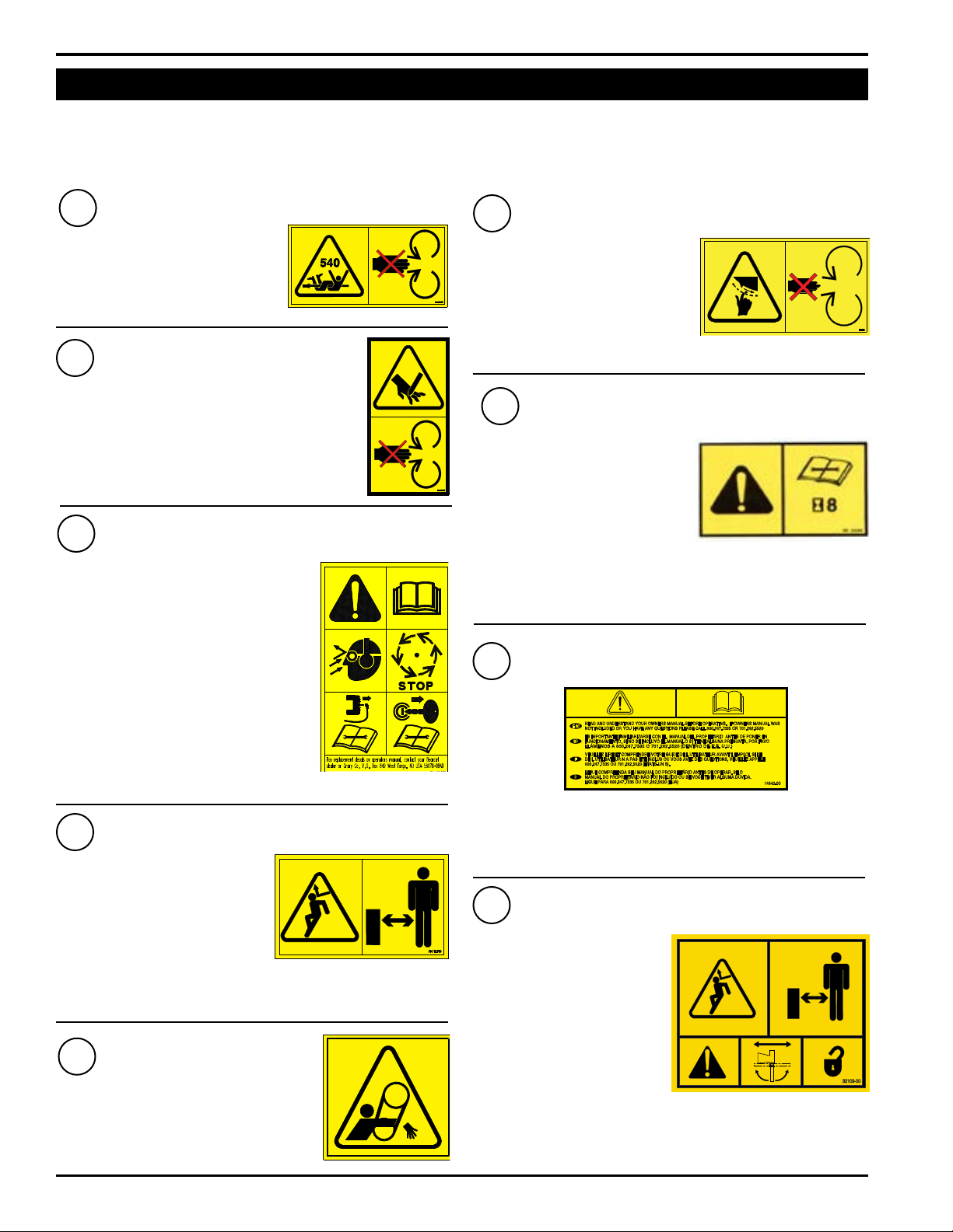
1.8 SAFETY DECALS
See Section 1.7 for decal locations. Familiarize yourself with all of the safety and operating decals on the machine and
the associated hazards. See the engine owners manual for engine safety instructions and decals. Make certain that
all safety and operational decals on this machine are kept clean and in good condition. Refer to the parts catalog if you
need a replacement decal. Decals that need replacement must be applied to their original locations.
1
KEEP HANDS, FEET AND
BODY AWAY FROM DRIVELINE
WHILE MACHINE IS OPERATING
TO AVOID ENTANGLEMENT.
OPERATE MACHINE AT 540 RPM.
2
KEEP HANDS AND FEET OUT OF INLET AND
DISCHARGE OPENINGS WHILE MACHINE IS
OPERATING TO AVOID SERIOUS PERSONAL
INJURY. ALLOW MACHINE TO COME TO
A COMPLETE STOP BEFORE CLEARING
OBSTRUCTIONS.
3
READ AND UNDERSTAND THIS
OWNER/OPERATORS MANUAL. BE
COMPLETELY FAMILIAR WITH THE
CONTROLS AND THE PROPER USE
OF THIS EQUIPMENT. OBTAIN AND
WEAR SAFETY GLASSES AND USE
HEARING PROTECTION AT ALL TIMES
WHEN OPERATING THIS MACHINE.
BEFORE INSPECTING OR SERVICING
ANY PART OF THIS MACHINE, SHUT
OFF POWER SOURCE, DISCONNECT
SPARK PLUG WIRE FROM SPARK
PLUG AND MAKE SURE ALL MOVING
PARTS HAVE COME TO A COMPLETE STOP.
4
DO NOT OPERATE THIS
EQUIPMENT IN THE VICINITY
OF BYSTANDERS. DO NOT
ALLOW CHILDREN TO
OPERATE THIS EQUIPMENT.
ALWAYS STAND CLEAR OF
DISCHARGE AREA WHEN
OPERATING THIS MACHINE. KEEP FACE AND BODY AWAY
FROM DISCHARGE AREAS.
5
DO NOT OPERATE MACHINE
WITHOUT SHIELDS IN PLACE.
FAILURE TO DO SO MAY CAUSE
SERIOUS INJURY OR DEATH.
PN 12168
PN 12169
PN 12172
PN 12173
PN 12174
PN 12174
6
KEEP HANDS AND FEET OUT
OF INLET AND DISCHARGE
OPENINGS WHILE MACHINE IS
OPERATING TO AVOID SERIOUS
PERSONAL INJURY. ALLOW
MACHINE TO COME TO A
COMPLETE STOP BEFORE CLEARING OBSTRUCTIONS.
CHECK BLADE BOLTS FOR
PROPER TORQUE AFTER EVERY
8 HOURS OF OPERATION.
CHECK BLADES AND ROTATE
OR RESHARPEN DAILY OR AS
REQUIRED TO KEEP BLADES
SHARP. REFER TO OWNERS
MANUAL FOR INSTRUCTIONS. FAILURE TO DO SO MAY CAUSE
POOR PERFORMANCE, DAMAGE OR PERSONAL INJURY AND
WILL VOID THE MACHINE WARRANTY.
8
READ AND UNDERSTAND YOU OWNERS MANUAL BEFORE
OPERATING. IF OWNERS MANUAL WAS NOT INCLUDED OR
YOU HAVE ANY QUESTIONS, PLEASE CALL 800.247.7335
OR 701.282.5520 (U.S.A.)
9
DO NOT OPERATE THIS
EQUIPMENT IN THE
VICINITY OF BYSTANDERS.
DO NOT ALLOW CHILDREN
TO OPERATE THIS
EQUIPMENT. ALWAYS
STAND CLEAR OF
DISCHARGE AREA WHEN
OPERATING THIS MACHINE.
KEEP FACE AND BODY
AWAY FROM DISCHARGE
AREAS. ROTATE THE DISCHARGE TUBE OVER THE HITCH
BEFORE TOWING AND LOCK SECURELY IN PLACE.
PN 12175
7
PN 12250
PN 14942-00
PN 32109-00
4
5 INCH CHIPPER
Page 9
2
Section
ASSEMBLY
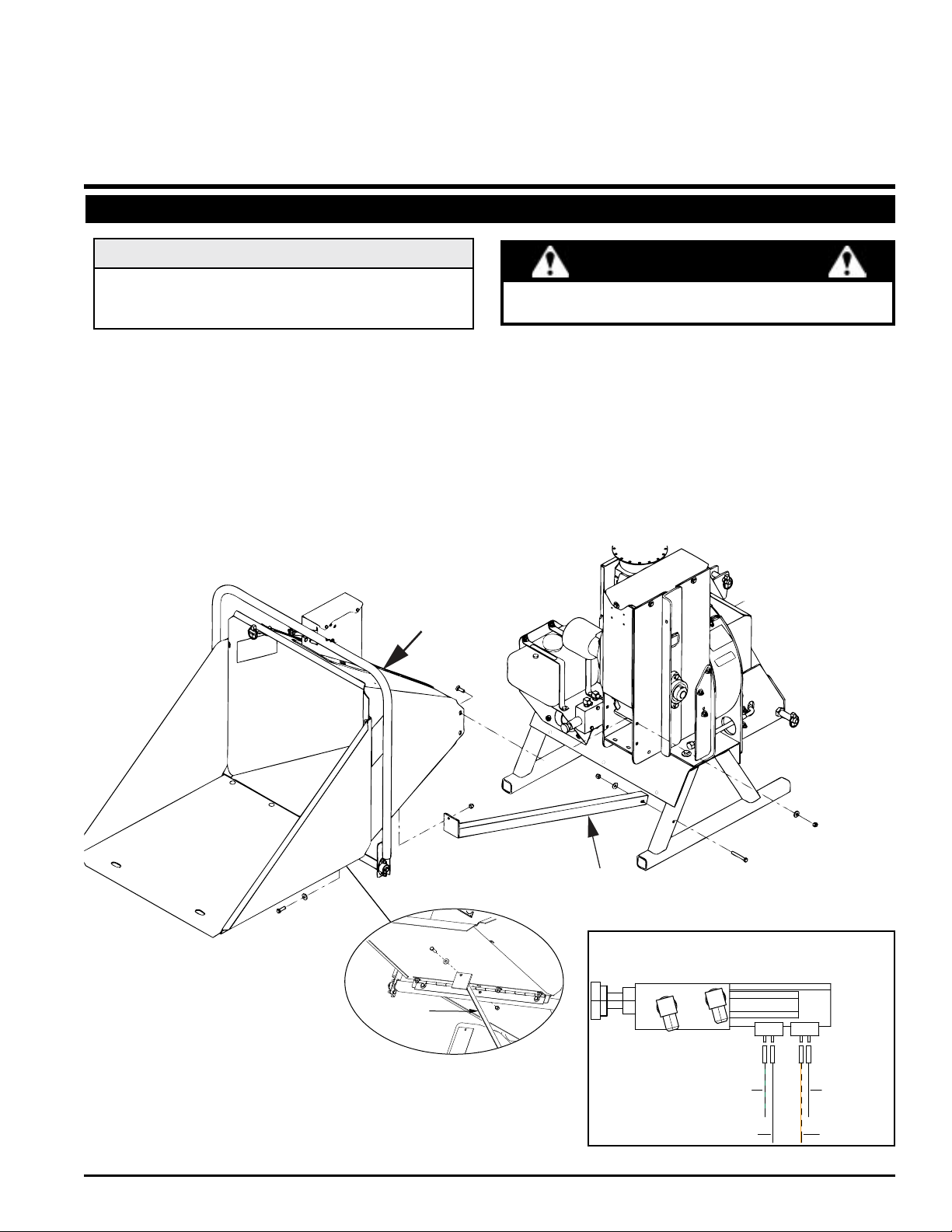
2.1 ATTACH CHUTE AND SUPPORT
NOTE
If forward and reverse feed positions are reversed when
you power up the machine, you may have plugged the
connectors into the wrong plug.
1. Mount the feed chute to the chipper housing using six 3/8 x 1-1/4" carriage bolts, 3/8" washers, and 3/8" nylock nuts (see
Figure 2.1). (Do not tighten until after step 3.)
2. Secure the chute support to the chipper leg stand with one 3/8 x 2-3/4" bolt, one 3/8" washer, and one 3/8" nylock nut as
shown in Fig. 2.1.
3. Secure the other end of the chute support by removing the middle bolt holding the feed chute to the hinge (shown in Fig
2.1 insert). Put the support bracket end between the washer and the hinge, and then retighten the bolt and nut.
4. Connect the four wires coming from the feed chute to the connectors located on the hydraulic control valve as shown
in Figure 2.2. The extra wire with a ring terminal end is only used if adding a LOFA auto feed controller option.
If any bolts or nuts are dropped in the machine, be
sure to remove them before starting the machine.
WARNING
FEED
CHUTE
ENGLISH
SUPPORT
BRACKET
Figure 2.1 Attach the discharge tube deector
FEED
CHUTE
5 INCH CHIPPER
CHUTE
SUPPORT
12646 VALVE,
HYDRAULIC CONTROL
GRN/BLK
BLACK
Figure 2.2
BLACK
ORG/BLK
5
Page 10

ASSEMBLY
2.2 ATTACH DISCHARGE TUBE
1. Attach one clamping ring(1) and one spacer ring(2) to
discharge tube base(3) using three 3/8 x 1 1/4" bolts(4)
and nylock nuts(5). Tighten leaving 1/16" gap to assist
in mounting to flange. See Figure 2.3.
5
3
2
Figure 2.3, Attach clamp ring and spacer
2. Slide the tube onto the mounting flange on the chipper
frame. The discharge clamp(1) should slide underneath
the lip of the flange. Tighten the bolts and nuts to
secure it.
3. Install the second half of the spacer(2) and clamp
ring(1) on the discharge tube with 3/8 x 1-1/4" bolts(4)
and nylock nuts(5).
4. Attach lanyard with discharge pin (11) as shown in
Figure 2.4.
1
4
NOTE
Keep nuts as tight as possible while allowing the
discharge tube to freely turn.
5. Lubricate the chute by applying grease to the grease
zerk at the base of the chute. Rotate the chute and
apply grease until the chute rotates freely.
6. Rotate the tube 360 degrees and lock it in place with
the lock pin to make sure it is mounted correctly.
7. Attach the discharge deflector(6) to the discharge tube.
Connect the deflector with two 5/16 X 1 1/4" bolts(7)
through the lower hole in the discharge tube. Run these
bolts through the inside of the tube, washer, deflector,
washer, and then knob(8).
8. Finish bolting the deflector to the tube with two 5/16 x
1" bolts(9) through the end hole in the discharge tube
and secure with 5/16 washers & nylock nuts(10).
6
9
7
10
8
11
5
2
1
4
Figure 2.4, Attach discharge tube
6
5 INCH CHIPPER
Figure 2.5, Attach discharge deflector
Page 11

2.3 CONNECT PTO DRIVELINE
The driveline supplied with this machine may need to be
cut to a shorter length for proper operation with the tractor
being used. To determine if driveline will need to be cut,
follow steps below or consult attached driveline manual.
1. BEFORE ATTACHING THE DRIVELINE: attach the
machine to the tractor with three-point hitch system.
2. Raise and lower machine on three-point hitch to determine
the shortest possible working distance between the tractor
PTO shaft and the drive shaft of the machine.
3. Pull the driveline apart so the two pieces are separated.
Connect the piece with 6-splined connector to tractor
and the other piece to the machine.
4. Position installed driveline halves parallel to one another.
(Photo below is example of driveline overlap.)
ASSEMBLY
IMPORTANT
• The tractor must have a standard 540 RPM PTO shaft.
• If the tractor has an electric PTO clutch, consult your dealer
for correct operating procedures.
• Consult the attached GKN Walterscheid driveline manual for
complete service and maintenance recommendations.
7. After cutting plastic tubes, measure 1-9/16" (40mm)
from the ends of both newly cut plastic tubes.
8. Mark the inner steel shafts and cut both shafts at 1-9/16"
(40mm) as shown in photos below.
ENGLISH
5. On larger outer tube, measure back 1-1/4" (32mm)
from lower yoke shield and mark plastic tube. Repeat
this process for smaller inner plastic tube measuring
1-1/4" (32mm) back from upper yoke shield.
YOKE
SHIELD
1-1/4" FROM SHIELD
OUTER
TUBE
YOKE
SHIELD
1-1/4" FROM SHIELD
STEEL
SHAFT
STEEL
SHAFT
1-9/16" (40mm)
OUTER
TUBE
INNER
TUBE
9. File both shaft ends to remove sharp edges and slide
the driveline pieces back together.
10. When you have confirmed that the driveline is the
correct length for your tractor, connect the driveline
to the chipper rotor shaft using key stock and two set
screws in the owner’s kit.
11. Connect the opposite end of the PTO shaft to the
tractor.
INNER
TUBE
6. Remove driveline pieces (for ease of cutting) and cut
ONLY the outer and inner plastic tubes.
5 INCH CHIPPER
7
Page 12

3
FEATURES AND CONTROLS
Section
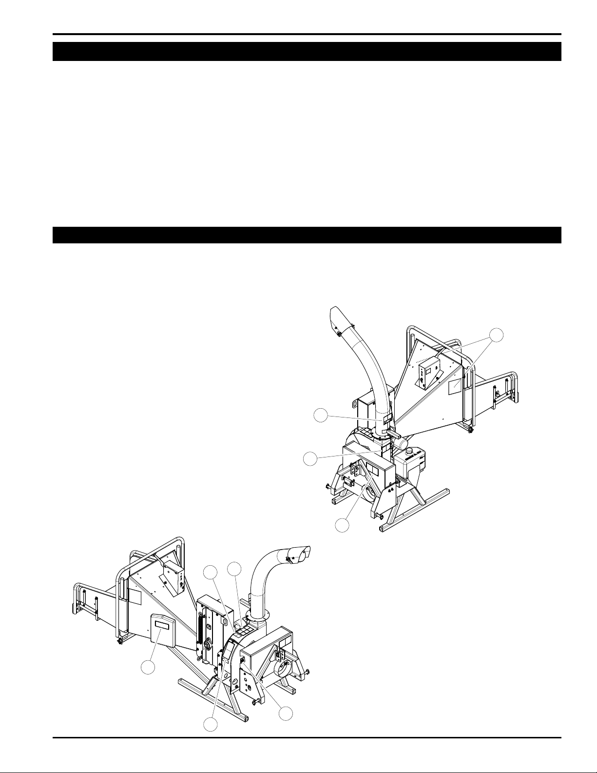
Understanding how your machine works will help you achieve the best results when using your machine. The following
descriptions dene the features and controls of your machine.
1. Belt Guard: Remove to grease rotor and jack shafts
and to check or replace belt.
2. Discharge Lock: Used to pivot and lock the discharge
chute.
3. Feed Roller Jack: Use the feed roller jack to raise the
feed roller to remove jammed materials.
4. Flow Control Knob: To adjust feed rate, first loosen
the inner jam nut, then turn the knob clockwise to increase
feed roller speed or counterclockwise to decrease speed.
When desired speed is reached, tighten jam nut.
5. Hydraulic Feed Control: Engages and disengages
the feed roller.
6. Hydraulic Reservoir: Hold the hydraulic fluid. Check
fluid level periodically.
7. Leg Stands: Adjustable to allow proper driveline angle.
Do not move machine unless the legs clear the ground.
8. Safety Bar (CE Compliant models): Push in the safety
bar to stop forward feed. To restart forward feed, push the
reset/override button (not available on all models).
9. Three-Point Hitch Connections: Mount chipper to
tractor. Connect direct for categories 0 & 1. A bushing kit
must be installed on three point connections for category
2 hitches.
10. Controller Light: When the light is flashing green,
increase RPM. The feed roller can be shifted into Forward
when the controller light is steady green. See Section 6
for more information.
11. Reset/Override Button: Push the reset/override
button to begin operating the feed roller after the safety
bar has been activated.
10
11
2
1
9
6
3
5
8
7
4
8
5 INCH CHIPPER
Page 13

4
Section
OPERATION
WARNING
Move machine to a clear, level area outdoors before
starting. Do not operate in the vicinity of bystanders.
Make sure cutting chamber is empty before starting.
4.1 STARTING THE CHIPPER
1. Read and understand all safety warnings and chipping
guidelines contained in this manual before proceeding.
2. Connect PTO driveline to tractor as described in Sec.
2.4.
3. Adjust three-point top link so the chipper sits level.
4. Make sure the feed roller bar is in the Stop position. The
controller will flash red until the bar is in Stop. See Sec.
6 for a table of all flash codes for the controller light.
5. Start tractor engine and engage PTO (refer to tractor
owners manual). Increase engine speed to rated PTO
RPM until the controller light on the feed chute is
showing a steady green light.
4.2 STOPPING THE CHIPPER
1. Move tractor throttle to SLOW position.
2. Disengage PTO lever and shut off tractor engine.
3. Allow machine to come to a complete stop.
NOTE
The heavy rotor will continue to turn for some time after
the engine or tractor has been shut off. You can tell
that the rotor has stopped when no noise or machine
vibration is present. Inserting a branch into the chipper
chute to contact the blades will slow the rotor and
shorten stopping time.
WARNING
Before operating your machine, be sure you read
and understand all safety, controls and operating
instructions in this owner’s manual and on your
machine. Failure to follow these instructions can
result in serious injury or property damage.
4.3 OPERATING THE CHIPPER
ENGLISH
6. Engage the hydraulic feed by moving the hydraulic
feed control arm. The control arm has four positions:
Reverse, Forward, Stop, and Reverse.
7. Feed branches up to five inches in diameter into the
chipper.
8. Reverse the feed by moving the control arm to reverse
position if the chipper jams. Remove the branch and
rotate it before reinserting it into the chute.
9. Adjust the speed of the feed roller, if necessary, with
the flow control knob.
DANGER
Do not inspect or work on PTO drive area without
rst disengaging PTO and shutting off tractor. Allow
all moving parts to come to a complete stop.
WARNING
Read and follow all safety instructions in this manual.
Failure to operate the machine in accordance with
the safety instructions MAY RESULT IN PERSONAL
INJURY!
CAUTION
Obtain and wear safety glasses at all times when
operating the machine.
Do not wear loose fitting clothing.
The operator should always wear heavy boots, gloves,
pants and a long-sleeved shirt.
Use common sense and practice safety to protect
yourself from branches, sharp objects, and other
harmful objects.
5 INCH CHIPPER
9
Page 14

OPERATION
SAFETY BAR
WARNING
Never lean over the chipper chute to push objects into the
cutting device. Use a push stick or brush paddle.
Never use shovels or forks to feed brush. They can
cause extensive damage if they contact the blades.
In addition, metal pieces can be ejected from the
chipper chute and cause serious injury or death.
Never feed brush into the chute with your feet.
Never use hands or feet to clear materials that build up in
the chute.
The machine chips a variety of materials into a more
readily decomposed or handled condition. The following
guidelines will help you get started.
1. Gradually increase engine speed with the throttle
until full idle is achieved. When the controller light
is steady green the engine speed is high enough to
begin to chip.
2. Engage the hydraulic feed by pushing the feed roller
control arm into forward position.
WARNING
To prevent personal injury or property damage: shut
off engine and make sure that all moving parts have
come to a complete stop before servicing, adjusting,
or repairing machine. Disconnect the battery and
remove ignition key where applicable.
4.4 FEED ROLLER CONTROL BAR
The Feed Roller Control Bar is used to manually control
the direction of the feed roller rotation.
Move the feed roller control bar to FORWARD (F) when
you want the materials to feed into the chipper. The
controller light must be steady green.
Move the feed roller bar to REVERSE (R) when you want
the chipper push materials back out of the feed chute.
Move the feed roller bar to STOP to halt the rotation of the
feed roller.
3. Limbs fed in to the chipper chute must be 5 inches
(12 cm) in diameter or less. Trim side branches that
cannot be bent enough to feed into the chipper chute.
Hold small diameter branches together in a bundle and
feed in simultaneously.
4. Place limb, butt end first, into the chipper chute
until it contacts the chipper blades. The actual feed
rate of the limb into the chipper will depend on the type
of material fed and sharpness of the cutting blades.
5. Do not feed pieces of metal, rocks, bottles, cans,
or other foreign objects into the machine.
6. Feed brush from the side of the chipper chute, rather
than from the front. Step aside to avoid being hit by the
brush moving into the chipper.
7. Do not use the clutch to clear a plugged rotor. This
may cause belt damage. Refer to the instructions for
clearing a plugged rotor in the Service and Maintenance
section.
8. Alternate greener material with dry material to
lubricate the chipping blades for longer life and better
performance. Chipping dead, dry material will create
heat and dull the chipping blades quickly.
9. Sharpen the chipping blades periodically. Check
the sharpness of the blades every 5-15 hours. Refer
to the Service and Maintenance section for sharpening
instructions.
CE COMPLIANT MODELS ONLY
Push the Safety Bar in the event of an emergency and
forward feed will stop. Push the reset/override button to
resume forward feed after returning the safety bar to its
normal operating position.
Upon start-up, the controller light will glow a steady red.
Push the reset/override button to reset.
If false trips occur, the reset button can be held in for 5
seconds to override the system.
RESET/OVERRIDE
BUTTON (WHERE
AVAILABLE)
CONTROLLER
LIGHT
R
REVERSE
STOP
F
FORWARD
R
REVERSE
FEED ROLLER
CONTROL BAR
(WHERE
AVAILABLE)
10
5 INCH CHIPPER
Page 15

5
Section
SERVICE & MAINTENANCE
5.1 MAINTENANCE SCHEDULE
The items listed in this service and maintenance schedule
are to be checked, and if necessary, corrective action
taken. This schedule is designed for units operating under
normal conditions. If the unit is operating in adverse or
severe conditions, it may be necessary for the items to be
checked and serviced more frequently.
SEE ENGINE OWNER’S MANUAL FOR FURTHER
ENGINE MAINTENANCE AND TROUBLESHOOTING
INFORMATION.
5.2 SERVICE & MAINTENANCE SCHEDULE
SERVICE AND MAINTENANCE SCHEDULE
COMPONENT
HYDRAULIC OIL CHECK/FILL
ALL INTERNAL AND EXTERNAL NUTS AND BOLTS
MAINTENANCE
REQUIRED
CHECK TIGHTNESS
BEFORE
EACH USE
WARNING
To prevent personal injury or property damage: shut
off engine and make sure that all moving parts have
come to a complete stop before, servicing, adjusting or
repairing. Disconnect the battery and remove ignition
key where applicable.
FREQUENCY
EVERY 8
HOURS
EVERY 25
HOURS
EVERY 50
HOURS
EVERY 200
HOURS
ENGLISH
CHIPPER ANVIL
CHIPPER BLADES
ENTIRE MACHINE CLEAN
PTO CROSS JOURNALS LUBE
PTO INNER TUBES LUBE
PTO SHIELD RETAINING
BEARING
DRIVE BELT CHECK
HYDRAULIC DRIVE BELT CHECK
BELT TENSION CHECK
BELT/PULLEY ALIGNMENT CHECK
GREASE ZERKS LUBE
HYDRAULIC OIL FILTER REPLACE
(1) PERFORM MORE FREQUENTLY UNDER EXTREMELY DUSTY CONDITIONS.
(2) PERFORM MORE FREQUENTLY WHEN CHIPPING DRY OR DIRTY WOOD.
As the Limited Warranty states, failure by the Owner to perform normal maintenance will void the machine’s warranty. The aggressive,
high-speed nature of chipping REQUIRES THE OWNER TO PERFORM THE ABOVE LISTED NORMAL MAINTENANCE. Special consideration to maintain and re-torque the CHIPPER ANVIL, CHIPPER BLADES, AND ALL INTERNAL AND EXTERNAL NUTS AND BOLTS is the
sole responsibility of the Owner. Failure by the Owner to do so shall be cause for denial of warranty.
CHECK CLEARANCE AND
RE-TORQUE TO 75 FT-LBS.(2)
CHECK SHARPNESS AND
RE-TORQUE TO 25 FT-LBS.(1)
LUBE
5 INCH CHIPPER
11
Page 16

SERVICE & MAINTENANCE
BEFORE INSPECTING OR SERVICING ANY PART OF THIS MACHINE, SHUT OFF POWER SOURCE,
AND MAKE SURE ALL MOVING PARTS HAVE COME TO A COMPLETE STOP.
WARNING
5.3 CHIPPER BLADE MAINTENANCE
The chipper blades will eventually become dull, making
chipping difcult and adding extra strain on the machine.
CHECK THE SHARPNESS OF THE BLADES EVERY 5 - 15
HOURS OF OPERATION AND SHARPEN AS NEEDED.
The controller light will flash an amber code every 15 hours
as a reminder to check the chipper blades. To reset the
controller, see Sec. 6.
Your blades need to be sharpened if:
• Machine vibrates severely when material is fed into the
chipper.
• Small diameter branches do not self-feed.
• Chips discharge unevenly or have stringy tails,
especially when chipping green branches.
Before you sharpen the chipping blades, check for
permanent damage. Replace the blade if:
• There are cracks, broken corners or nicks greater than
1/8" (see below).
5.4 REMOVING CHIPPER BLADES
Chipping blades are sharp! Use caution when working on
machine to avoid injury.
Chipping blades are sharp! Use caution when working
on machine to avoid injury.
To remove the chipping blades for sharpening:
1. Remove the one 3/8" retaining bolt holding the access
cover to main frame assembly (see Fig. 5.1).
2. Tilt access cover over to allow rotor access. Rotate
the rotor so that the bolts holding a chipping blade are
most accessible.
3. Remove the two hex bolts holding the chipper blade.
4. Repeat for all four chipper blades.
5. Replace sharpened or new blades and torque to 25
ft-lbs.
WARNING
ACCESS
BOLT
CRACK
GREATER
THAN 1/8”
BROKEN
CORNER
NICK GREATER
THAN 1/8”
• The base of the cutting edge is worn or has been resharpened so that it no longer extends past the chipping
slot (see below).
CHIPPER
DISC
CHIPPING
SLOT
NEW
BLADE
CHIPPER
DISC
CHIPPING
SLOT
BLADE IS
TOO SHORT,
MUST BE
REPLACED
Figure 5.1 Access bolt
5.5 SHARPENING CHIPPER BLADES
The blades can be ground on a bench grinder or by a
professional.
1. Never sharpen or grind the mounting surfaces of the
blades. This will cause the edge to roll and the blade will
be damaged, resulting in poor chipping performance.
2. Regrind the angled edge of the chipping blades to 45
degrees (Figure 5.2). Make sure some type of fixture is
used to correctly hold the blade at the proper angle.
3. Be careful when grinding so that the blade does not
become overheated and change color. This will remove
the heat-treated properties.
4. Use short grinding times and cool with water or some
type of liquid coolant.
5. Remove an equal amount off each blade to maintain
rotor balance.
6. Small imperfections such as nicks and burrs on the flat
side of the blade will not affect the chipping performance
of the machine.
12
5 INCH CHIPPER
Page 17

WARNING
BEFORE INSPECTING OR SERVICING ANY PART OF THIS MACHINE, SHUT OFF POWER SOURCE,
AND MAKE SURE ALL MOVING PARTS HAVE COME TO A COMPLETE STOP.
7. For blades that have been repeatedly sharpened,
ensure that the sharpened surface extends past the
chipping slot opening. If it does not extend past the
opening, the blades should be replaced.
SERVICE & MAINTENANCE
5.7 CLEARING A PLUGGED ROTOR
Feeding too large or too much material at once may plug
the chipper. To clear a plugged disk, proceed as follows:
MOUNTING SURFACE
45°
.25
(DO NOT GRIND)
SHARPENED
SURFACE
Figure 5.2 Sharpening the blades
MOUNTING SURFACE
(DO NOT GRIND)
SHARPENED
SURFACE
5.6 SETTING BLADE CLEARANCE
The chipping blades should clear the anvil by 1/16 inch to
1/8 inch. Check the clearance every 8 hours of operation
and adjust if needed. The chipping anvil is reversible. All
four sides of the anvil can be used for chipping.
To adjust the anvil:
1. Lift rotor access cover and expose rotor. Loosen the
two 1/2" bolts that hold the chipper anvil to the frame.
2. Measure the amount of clearance between chipping
blade and chipper anvil from inside of housing. The
gap should be 1/16" to 1/8".
3. Adjust inward or outward to desired measurement. Use
the nuts on the adjustment bolt (See Fig. 5.3).
4. Tighten bolts on chipping block to 75 ft. lbs. and resume
operation.
Remove the two bolts holding the anvil and use one of the
other three edges if the chipper anvil edge is damaged or
worn unevenly. Adjust for correct measurement.
ANVIL
1. Allow all moving parts to come to a complete stop.
2. Remove the two 3/8” retaining bolts holding the access
cover to the chipper frame and lift up access cover.
3. Remove the lock pin from storage position (see
below).
4. Turn check valve clockwise to engage the jack pump.
5. Pump the handle to raise the feed roller until the lock pin
position aligns with one of the support bracket holes.
6. Secure the position by putting the lock pin through the
support bracket and lock pin position.
7. Clean the debris away from the chipper disk. Turn the
disk by hand to be sure it is free to rotate. Be careful
to avoid the chipper blades when cleaning out the
debris.
8. Remove the lock pin and put it back in storage
position. LEAVING THE LOCK PIN IN ANY OTHER
POSITION MAY INTERFERE WITH FEED ROLLER
OPERATION.
9. Turn the check valve counterclockwise to disengage
the pump and lower the jack.
10. Close access cover and replace bolts.
LOCK PIN IN
STORAGE
POSITION
ENGLISH
CHIPPER
BLADE
ROTOR
ANVIL
ADJUSTMENT
1/16" - 1/8"
Figure 5.3 Chipper blade and anvil clearance
FEED
ROLLER
JACK
CHECK
VALVE
5 INCH CHIPPER
SUPPORT
BRACKET
LOCK PIN
POSITION
Figure 5.4 Feed roller jack and lock pin
13
Page 18

SERVICE & MAINTENANCE
BEFORE INSPECTING OR SERVICING ANY PART OF THIS MACHINE, SHUT OFF POWER SOURCE,
AND MAKE SURE ALL MOVING PARTS HAVE COME TO A COMPLETE STOP.
WARNING
5.8 REPLACING DRIVE BELT
Check the condition of the drive belt annually or after
every 25 hours of operation, whichever comes rst. If the
belt is cracked, worn, frayed, or stretched, replace it.
To replace the belt:
1. Remove large belt guard by removing five 5/16" bolts
and washers.
2. Remove the idler pulley by removing the 4" bolt in the
center of the pulley (see Fig. 5.5).
3. Remove drive belt from pulleys.
4. Install new belt on pulleys.
5. Put idler pulley back in place and replace bolt.
6. Replace belt guard.
ROTOR
SHAFT
IMPORTANT
Polyurea and lithium-based greases are not
compatible. Mixing the two grease types may lead to
premature failure.
NOTE
Do not over grease bearings. Overlling can lead to
excessive heat and/or unseating of the seals. Add
grease slowly and under light pressure. Whenever
possible, rotate bearing slowly while lubricating.
IDLER
PULLEY
Figure 5.5 Belt and pulleys with belt shield removed
5.9 LUBRICATION
Lubricate the machine periodically with a lithium-based
grease. Extreme working conditions will require more
frequent greasing.
Grease the following points every 50 hours of operating
time:
1. Two zerks on the jack shaft (remove belt cover to
access).
2. Two zerks on the rotor shaft (remove belt cover to
access).
3. Two zerks on the feed roller shaft.
4. One grease zerk on the discharge chute.
Figure 5.6 Grease zerk on jack shaft
14
Figure 5.7 Grease zerks on discharge chute, other side of rotor
shaft, and other side of jack shaft
5 INCH CHIPPER
Page 19

WARNING
BEFORE INSPECTING OR SERVICING ANY PART OF THIS MACHINE, SHUT OFF POWER SOURCE,
AND MAKE SURE ALL MOVING PARTS HAVE COME TO A COMPLETE STOP.
Figure 5.8 Grease zerk on rotor shaft
Figure 5.9 Grease zerk on left side of feed roller
Figure 5.10 Grease zerk on right side of feed roller
5.10 PTO LUBRICATION
1. Every 8 hours, lubricate PTO cross journals. Make sure
grease purges through all four bearings.
2. Every 8 hours, lubricate PTO inner tubes. Telescoping
members must have lubrication to operate successfully.
Telescoping members without fittings should be pulled
apart and grease should be added manually with a
brush.
SERVICE & MAINTENANCE
3. Every 8 hours, lubricate the PTO shield retaining
bearing. Molded nipples on the guard near each guard
bearing are intended as grease fittings and should be
lubricated every 8 hours of operation.
h
8
8
8
h
h
h
8
h
8
5.11 REMOVING THE ROTOR
1. Remove the one 3/8" retaining bolt holding access
cover to main frame assembly. Tilt access cover over
to allow rotor access.
2. Remove large belt guard.
3. Remove belt idler pulley and remove drive belt from
pulleys.
4. Remove the bushing and pulley from the rotor shaft
using the push bolts from the bushing.
5. Remove the two 1/2 inch bolts on each rotor bearing.
6. Pound 1/4" roll pin out of the rotor shaft on front bearing.
7. Lift the rotor assembly completely out of the frame with
an overhead hoist or lifting device. The complete rotor
assembly is 140 lbs.
8. Remove both bearings with a puller when the rotor
assembly is out of the frame and place new bearings
on rotor shaft.
9. Replace roll pin with a new 1/2 x 2" pin, P/N 15137.
10. Return the complete rotor assembly to the chipper
frame with an overhead hoist or lifting device.
11. Slide rotor back until front roll pin is tight against the
front bearing.
12. Lock the front bearing and install the four 1/2" bolts
on each bearing to secure them to the frame. Tighten
bolts to 75 ft. lbs.
13. Check and adjust chipper anvil if needed. Lock rear
bearing.
14. Slide bushing onto shaft with flange tight against the
spacer.
15. Attach small pulley to bushing.
16. Replace drive belt on pulleys and lower belt idler. Check
alignment of pulleys and adjust engine if needed.
17. Close cover and replace bolts.
18. Replace belt guard and resume operation.
ENGLISH
5 INCH CHIPPER
15
Page 20

SERVICE & MAINTENANCE
BEFORE INSPECTING OR SERVICING ANY PART OF THIS MACHINE, SHUT OFF POWER SOURCE,
AND MAKE SURE ALL MOVING PARTS HAVE COME TO A COMPLETE STOP.
WARNING
5.12 FILLING HYDRAULIC FLUID
CAUTION
Handle pressurized hydraulic uid carefully. Escaping
pressurized hydraulic uid can have sufcient force to
penetrate your skin causing serious injury. This uid
may also be hot enough to burn. Serious infection or
reactions can develop if proper medical treatment is
not administered immediately.
Hydraulic uid drives the feed roller. Check the uid
level daily and ll as needed. The uid and lter should
be changed and system cleaned if the uid becomes
contaminated with foreign matter (water, dirt, grease, etc.)
or if the uid has been subjected to temperatures greater
than the maximum recommended.
The hydraulic pump requires premium hydraulic uids
containing high quality rust, oxidation, and foam inhibitors.
These include premium turbine oils, API CD engine oils
per SAE J183, M2C33F or G automatic transmission
uids meeting Allison C-3 or Caterpillar TO-2, and certain
specialty agricultural tractor uids.
In the unlikely event that the oil is completely drained
from the hydraulic system, oil must be added and any air
bubbles must be purged from the system. To do this:
5.13 CHANGING HYDRAULIC OIL FILTER
Change the hydraulic oil lter after the rst 50 hours of
operation and every 200 hours thereafter.
To change the hydraulic oil lter:
1. Using an oil filter wrench, turn the filter
counterclockwise.
2. Once the filter becomes loose, turn it out the rest of the
way with your hand.
3. Properly discard old filter.
4. Lube the rubber seal on the new filter (PN 16922) with
clean hydraulic oil.
5. Install the filter onto the threaded pipe. Turn with your
hand until the filter is finger tight.
6. Using an oil filter wrench, tighten the filter another ½
turn.
7. Check hydraulic oil level and fill if necessary.
CAUTION
Hydraulic systems contain uid under high pressure.
Never check for leaks with your hands. Relieve
pressure before disconnecting any hydraulic lines.
1. Clean all system components (reservoir, fittings,
etc.).
2. Fill the hydraulic reservoir.
3. Start the engine and run at the lowest possible RPM.
4. As you purge air from the unit, the oil level in the reservoir
will drop and bubbles may appear in the fluid. Refill the
reservoir as necessary.
5. Run the feed roller in both directions for several minutes
until any remaining air purges from the unit. Refill the
reservoir as necessary.
6. Shut down the engine, check for and correct any
fluid leaks, and check the reservoir level. Add fluid
if necessary. The hydraulic pump is now ready for
operation.
HYDRAULIC
FILTER
16
5 INCH CHIPPER
Page 21

6
Section
TROUBLESHOOTING
6.1 FLASH CODES FOR CONTROL LIGHT
GUIDE TO THE CONTROLLER FLASH CODES
SIGNAL FREQUENCY CAUSE ACTION TO TAKE
GREEN SOLID
GREEN
GREEN
RED
½ second on,
½ second off
½ second on,
½ second off
½ second on,
½ second off
GREEN
Chipper has reached
default chipping RPM and
forward feed is available.
Chipper has not reached
chipping RPM upon initial
startup.
Chipper RPM dropped
while chipping.
RED
Feed bar not in NEUTRAL
upon initial startup.
ENGLISH
Machine available for
standard use.
Slowly increase RPM.
Feed roller will
automatically reverse to
bring RPM back up.
Place feed bar in
NEUTRAL.
RED SOLID
RED FLASHING
AMBER
AMBER
AMBER
2 seconds on,
2 seconds off
Solid for 7 seconds, then a
long pause, then repeat
½ second on,
½ second off
Safety bar was activated
and forward coil or reverse
coil faults are not active.
Machine has been below
operational RPM for more
than 10 minutes.
AMBER
Blade service code is
active, feed bar was placed
in NEUTRAL after power
up and the control system
has not detected chipper
RPM.
Forward infeed coil fault. If
active all other codes are
ignored.
Reverse coil fault. If active
all other codes are ignored.
Push Safety Bar Reset/
Override Switch.
10 minute timer is a safety
feature and will require the
safety bar to be returned to
NEUTRAL position before
operation can resume.
Service blades. Reset
code by turning key on
and shift the feed bar from
REVERSE to REVERSE
then back 3 times. This
must be done within 60
seconds of turning key on
and the engine cannot be
running.
Test wiring to forward
coil. Replace coil if out of
specication.
Test wiring to reverse
coil. Replace coil if out of
specication.
5 INCH CHIPPER
17
Page 22

TROUBLESHOOTING
6.2 TROUBLESHOOTING GUIDE
PROBLEM POSSIBLE CAUSES REMEDY
Controller light ashes
green.
Forward feed is not
available.
Controller light ashes
red.
Upon shifting to STOP,
controller ashes red.
During chipping the
sensor gives a solid
green light, but feed roller
runs intermittently.
Controller light is not on. No power to controller. Check the resettable fuse breaker.
Controller ashes amber
light
Chipper disk RPM not high
enough to chip.
Chipper disk RPM not high
enough to chip.
Feed roller control bar is not in
STOP position.
RPM dropped too low for 10
seconds.
Sensors are not adjusted
properly.
Disk RPM sensor is set too far
away from the disk.
Controller is giving service
code.
Increase throttle gradually until light turns solid green.
The belt could be slipping. Adjust belt tension or replace belt if worn.
Flashing green light on the controller indicates RPM is not high
enough. Increase throttle gradually until light turns solid green.
Flashing red light on the controller indicates the chipper is not in
STOP position. Put control bar in STOP and then reengage.
Put control bar in STOP.
Put control bar in STOP position and then reengage.
Check sensors located above the feed chute. Gap should be 1/32”
(thickness of a credit card).
Open the shield and check disk sensor. Gap should be 1/32”
(thickness of a credit card).
Consult Flash Codes Guide and perform necessary maintenance.
Reset controller.
Machine chips poorly.
Hard to feed chipper;
requires excessive power
to chip.
Belt squeals when
engaging belt.
Excessive vibration while
running.
Dull chipper blades. Flip or sharpen blades.
Drive belts loose or worn. Inspect drive belts, adjust or replace if needed.
Attempting to feed branches
that are too large.
Dull chipper blades. Flip or sharpen blades.
Obstructed discharge. Use branch or similar object to clear discharge.
Improper blade clearance. Set blade/anvil clearance to recommended distance.
Engaging belt too fast. Engage belt more slowly.
Belt tension too loose. Replace belt or spring.
Dull chipper blades. Flip or sharpen blades.
Drive system vibration.
Disk out of balance.
Limit branch size to 5 inches in diameter.
Check drive belts, bearings, and pulleys for bad or worn areas.
Check for dull chipper blades or shredder knives.
Inspect rotor for damaged or missing chipper blades; replace if
needed.
18
Chipper blade to anvil clearance
is incorrect.
5 INCH CHIPPER
Set blade/anvil clearance to recommended distance.
Page 23

TROUBLESHOOTING
Cannot engage belt.
Excessive belt wear.
Improper belt installation; belt
not under belt guide.
Improper belt tension. Adjust belt tension. Replace belt or spring if needed.
Not using correct belt.
Pulley(s) damaged or worn. Replace pulley(s).
Pulley(s) not in alignment. Align pulley(s) to within 1/16” with straight edge.
Belt(s) tension too loose. Replace belt or spring.
Install belt properly; install belt under belt guide.
Contact your nearest authorized dealer to order the correct belt for
your chipper.
ENGLISH
5 INCH CHIPPER
19
Page 24

7
SPECIFICATIONS
Section
CH5540H
DESCRIPTION ENGLISH METRIC
OVERALL SIZE 49" x 68" x 90"
OVERALL WEIGHT 980 lbs. 445kg
MAX CHIPPER CAPACITY 5 " 12 cm
CHIPPER BLADES
DISC SIZE 20" x 1.25"
DISC WEIGHT 140 lbs. 63.5kg
DISCHARGE SIZE 6" 15 cm
DRIVE TYPE Belt Belt
BELT SIZE 4L350 4L350
HYDRAULIC FEED RATE 3 gal / minute 11.36 L / minute
PTO 540 +/- 10 RPM 540 +/- 10 RPM
4 Reversible
Tool Steel
124cm x 172,7cm x
228,6cm
4 Reversible
Tool Steel
51 cm x
3.175 cm
20
5 INCH CHIPPER
Page 25

SPECIFICATIONS
BOLT TORQUE
The tables below are for reference purposes only and their use by anyone is entirely voluntary, unless otherwise noted.
Reliance on their content for any purpose is at the sole risk of that person and any loss or damage resulting from the
use of this information is the responsibility of that person.
SAE
Grade
and
Head
Markings
SAE - 2
SAE - 5
SAE - 8
BOLT DIAMETER
A
ENGLISH
BOLT DIAMETER (A)
1/4” 7.5 5.5 11 8 16 12
5/16” 15 11 23 17 34 25
3/8” 27 20 41 30 61 45
7/16” 41 30 68 50 95 70
1/2” 68 50 102 75 149 11 0
9/16” 97 70 149 11 0 203 150
5/8” 122 90 203 150 312 230
3/4” 217 160 353 260 515 380
7/8” 230 170 542 400 814 600
1” 298 220 786 580 1220 900
1-1/8” 407 300 1085 800 1736 1280
1-1/4” 570 420 2631 1940 2468 1820
SAE 2 SAE 5 SAE 8
N.m Ft-lb. N.m Ft-lb. N.m Ft-lb.
BOLT TORQUE *
* Torque value for bolts and
capscrews are identified by their
head markings.
Torque figures indicated above are
valid for non-greased or non-oiled
threads and heads unless otherwise
specified. Therefore, do not grease
or oil bolts or capscrews unless
otherwise specified in this manual.
When using locking elements,
increase torque values by 5%.
ENGLISH
METRIC
Grade
and
Head
Markings
4.8
4.8
8.8
8.8 10.9
10.9
12.9
12.9
BOLT DIAMETER
A
METRIC
BOLT DIAMETER
(A)
M3 0.5 0.4 - - - - - -
M4 3 2.2 - - - - - -
M5 5 4 - - - - - -
M6 6 4.5 11 8.5 17 12 19 14.5
M8 15 11 28 20 40 30 47 35
M10 29 21 55 40 80 60 95 70
M12 50 37 95 70 140 105 165 120
M14 80 60 150 110 225 165 260 190
M16 125 92 240 175 350 255 400 300
M18 175 125 330 250 475 350 560 410
M20 240 180 475 350 675 500 800 580
M22 330 250 650 475 925 675 1075 800
M24 425 310 825 600 1150 850 1350 1000
M27 625 450 1200 875 1700 1250 2000 1500
4.8 8.8 10.9 12.9
N.m Ft-lb. N.m Ft-lb. N.m Ft-lb. N.m Ft-lb.
BOLT TORQUE *
5 INCH CHIPPER
21
Page 26

8
Section
OPTIONS
Part # DECSCRIPTION
72493 CHIPPER BLADE KIT
73071 AUTO FEED KIT
AUTO FEED KIT, 73071
CHIPPER BLADE KIT, 72493
22
5 INCH CHIPPER
Page 27

ECHO BEAR CAT
www.bearcatproducts.com
237 NW 12th Street, West Fargo, ND 58078-0849
Phone: 701.282.5520 • Toll Free: 888.645.4520 • Fax: 701.282.9522
E-mail: service@bearcatproducts.com • sales@bearcatproducts.com
 Loading...