

Page 1
www.bearcatproducts.com
4.5 INCH
HYDRAULIC
CHIPPER
CH450H - UTILITY LOADER ATTACHMENT
Rev. 010113
Manual P/N 36493-00
SN Range: D00001 - Current
OWNER'S/PARTS MANUAL
Page 2

Before You Begin
DEAR ECHO BEAR CAT CUSTOMER
Thank you for purchasing a ECHO Bear Cat product. The ECHO Bear Cat line is designed, tested, and manufactured
to give years of dependable performance. To keep your machine operating at peak efciency, it is necessary to adjust
it correctly and make regular inspections. The following pages will assist you in the operation and maintenance of your
machine. Please read and understand this manual before operating your machine.
If you have any questions or comments about this manual, please call us toll-free at 1.888.645.4520.
If you have any questions or problems with your machine, please call or write your local authorized ECHO Bear Cat Dealer.
This document is based on information available at the time of its publication. ECHO Bear Cat is continually making
improvements and developing new equipment. In doing so, we reserve the right to make changes or add improvements
to our product without obligation for equipment previously sold.
PLEASE SEND US YOUR WARRANTY CARD
A warranty card is included in your owner's kit packaged with your machine. Please take the time to ll in the information
requested on the card. When you send your completed card to us, we will register your machine and start your coverage
under our limited warranty or go to bearcatproducts.com/warranty/warranty-registration/.
FOR MACHINE SERVICE OR PARTS:
For service assistance, contact your nearest authorized
ECHO Bear Cat dealer or the factory. For parts, contact
your authorized dealer. Your dealer will need to know the
serial number of your machine to provide the most efcient
service. See below for information on how to identify and
record the serial number for your machine.
FOR ENGINE SERVICE OR PARTS:
For engine service or parts, contact your nearest authorized
engine dealer. ECHO Bear Cat does not handle any parts,
repairs or warranties for engines.
SERIAL NUMBER LOCATION
Please record the serial number in the space provided and
on the warranty and registration card.
MANUFACTURED BY CRARY INDUSTRIES
WEST FARGO, NORTH DAKOTA 58078 U.S.A.
SERIAL NUMBER
MANUFACTURED IN U.S.A.
XXXXXX
ORDERING PARTS
Only genuine ECHO Bear Cat replacement parts should
be used to repair the machine. Replacement parts
manufactured by others could present safety hazards,
even though they may t on this machine. Replacement
parts are available from your ECHO Bear Cat dealer.
Provide the following when ordering parts:
The SERIAL NUMBER of your machine.
The PART NUMBER of the part.
The PART DESCRIPTION.
The QUANTITY needed.
SERIAL NUMBER
HOW TO CONTACT ECHO BEAR CAT
ADDRESS PHONE E-MAIL HOURS
237 NW 12th Street
P.O. Box 849
West Fargo, ND 58078
*Original Instructions
© 2013, CRARY INDUSTRIES, ALL RIGHTS RESERVED. PRODUCED AND PRINTED IN THE U.S.A.
888.645.4520
701.282.5520
FAX: 701.282.9522
sales@bearcatproducts.com
service@bearcatproducts.com
Monday - Friday,
8 am to 5 pm
Central Time
Page 3

LIMITED WARRANTY
This warranty applies to all ECHO Bear Cat Outdoor Power Equipment manufactured by Crary Industries Inc.
Crary Industries warrants to the original owner each new ECHO Bear Cat product to be free from defects in
material and workmanship, under normal use and service. The warranty shall extend, from date of purchase,
3 years (U.S. and Canada only (2 years outside U.S. and Canada)) for Consumer use of the product, 1 year
for Commercial applications and 6 months for Rental applications.
“Consumer” defined as: complete unit for personal, residential or non-income producing use.
“Commercial” defined as: complete unit for commercial, institutional, property management, agricultural,
horticultural or income producing use.
“Rental” defined as: complete unit for rental purposes to produce income.
*Models SC2170, SC2206 & SC3206 are classified as Consumer grade products and will not qualify for
warranty coverage if used for Commercial or Rental purposes.
The product is warranted to the original owner as evidenced by a completed warranty registration on file at
Crary Industries. Replacement parts are warranted for (90) days from date of installation.
THE WARRANTY REGISTRATION MUST BE COMPLETED AND RETURNED TO CRARY INDUSTRIES
WITHIN 10 DAYS OF DELIVERY OF THE PRODUCT TO THE ORIGINAL OWNER OR THE WARRANTY
WILL BE VOID.
In the event of a failure, return the product, at your cost, along with proof of purchase to the selling ECHO
Bear Cat dealer. Crary Industries will, at its option, repair or replace any parts found to be defective in material
or workmanship. Warranty on any repairs will not extend beyond the product warranty. Repair or attempted
repair by anyone other than an authorized ECHO Bear Cat dealer as well as subsequent failure or damage
that may occur as a result of that work will not be paid under this warranty. Crary Industries does not warrant
replacement components not manufactured or sold by Crary Industries.
1. This warranty applies only to parts or components that are defective in material or workmanship.
2. This warranty does not cover normal wear items including, but not limited to: bearings, belts, pulleys,
filters, chipper blades, shredder flails or knives.
3. This warranty does not cover normal maintenance, service or adjustments.
4. This warranty does not cover depreciation or damage due to misuse, negligence, accident or improper
maintenance.
5. This warranty does not cover damage due to improper setup, installation or adjustment.
6. This warranty does not cover damage due to unauthorized modifications of the product.
7. Engines are warranted by the respective engine manufacturer and are not covered by this warranty.
Crary Industries is not liable for any property damage, personal injury or death resulting from the unauthorized
modification or alteration of an ECHO Bear Cat product or from the owner’s failure to assemble, install, maintain
or operate the product in accordance with the provisions of the Owner’s manual.
Crary Industries is not liable for indirect, incidental or consequential damages or injuries including but not
limited to loss of crops, loss of profits, rental of substitute equipment or other commercial loss.
This warranty gives you specific legal rights. You may have other rights that may vary from area to area.
Crary Industries makes no warranties, representations or promises, expressed or implied as to the performance
of its products other than those set forth in this warranty. Neither the dealer nor any other person has any
authority to make any representations, warranties or promises on behalf of Crary Industries or to modify the
terms or limitations of this warranty in any way. Crary Industries, at its discretion, may periodically offer limited,
written enhancements to this warranty.
CRARY INDUSTRIES RESERVES THE RIGHT TO CHANGE THE DESIGN AND/OR SPECIFICATIONS OF
ITS PRODUCTS AT ANY TIME WITHOUT OBLIGATION TO PREVIOUS PURCHASERS OF ITS PRODUCTS.
Page 4

TABLE OF CONTENTS
DESCRIPTION PAGE
SAFETY ................................................................................................................ 1
1.1 SAFETY ALERT SYMBOL ....................................................................................1
1.2 BEFORE OPERATING ..........................................................................................1
1.3 OPERATION SAFETY ..........................................................................................2
1.4 MAINTENANCE & STORAGE SAFETY ...............................................................2
1.5 SAFETY DECAL LOCATIONS ..............................................................................2
1.6 SAFETY DECALS ................................................................................................3
ASSEMBLY ........................................................................................................... 4
2.1 DISCHARGE ASSEMBLY .....................................................................................4
2.2 CHUTE ASSEMBLY ..............................................................................................4
FEATURES & CONTROLS ................................................................................... 5
OPERATION ......................................................................................................... 6
4.1 RECOMMENDED HYDRAULIC FLOW RATES ...................................................6
4.2 MOUNTING THE CHIPPER TO A UTILITY LOADER ...........................................6
4.3 REMOVING THE CHIPPER FROM A UTILITY LOADER .....................................6
4.4 CONNECTING COUPLERS .................................................................................7
4.5 STARTING THE CHIPPER ...................................................................................7
4.6 STOPPING THE CHIPPER ...................................................................................7
4.7 OPERATING THE CHIPPER ................................................................................8
SERVICE & MAINTENANCE ................................................................................ 9
5.1 MAINTENANCE SCHEDULE................................................................................9
5.2 INSTALLING THE DISK LOCK .............................................................................9
5.3 CHIPPER BLADE MAINTENANCE ....................................................................10
5.4 REMOVING THE BLADES .................................................................................10
5.5 SHARPENING THE BLADES .............................................................................10
5.6 INSTALLING THE BLADES ................................................................................11
5.7 SETTING BLADE CLEARANCE .........................................................................11
5.8 LUBRICATION ....................................................................................................11
5.9 REPLACING ROTOR BEARINGS ......................................................................12
5.10 CLEARING A PLUGGED DISK .........................................................................12
TROUBLESHOOTING ........................................................................................ 13
SPECIFICATIONS ............................................................................................... 14
7.1 SPECIFICATIONS ...............................................................................................14
7.2 BOLT TORQUE ...................................................................................................15
PARTS ................................................................................................................. 16
8.1 PARTS ORDERING INFORMATION ...................................................................16
8.2 REPLACEMENTS PARTS ...................................................................................16
8.3 BASE & HOUSING...............................................................................................16
8.4 ROTOR & HYDRAULICS .....................................................................................18
8.5 ATTACHMENTS ...................................................................................................20
8.6 SERVICE PARTS & OPTIONS ...........................................................................22
iv 4.5 INCH HYDRAULIC CHIPPER
Page 5
1
Section
SAFETY
1.1 SAFETY ALERT SYMBOL
The Owner/Operator’s manual uses this symbol to alert
you of potential hazards. Whenever you see this symbol,
read and obey the safety message that follows it. Failure
to obey the safety message could result in personal injury,
death or property damage.
DANGER
Indicates an imminently hazardous situation that, if not
avoided, will result in death or serious injury.
3. Keep safety decals clean and legible. Replace missing
or illegible safety decals.
4. Obtain and wear safety glasses and
use hearing protection at all times
when operating this machine.
5. Avoid wearing loose fitted clothing.
Never operate this machine while
wearing clothing with drawstrings that could wrap
around or get caught in the machine.
6. Do not operate this machine if you are under the
influence of alcohol, medications, or substances that
can affect your vision, balance or judgment. Do not
operate if tired or ill. You must be in good health to
operate this machine safely.
7. Do not operate this equipment in the vicinity of
bystanders. Keep the area of operation clear of all
persons, particularly small children. It is recommended
that bystanders keep at least 50 feet (15 meters) away
from the area of operation.
8. Do not allow children to operate this equipment.
WARNING
Indicates a potentially hazardous situation that, if not
avoided, could result in death or serious injury.
CAUTION
Indicates a potentially hazardous situation that, if not
avoided, may result in minor or moderate injury.
1.2 BEFORE OPERATING
1. Read and understand this owner’s manual. Be
completely familiar with the controls and the proper
use of this equipment.
2. Familiarize yourself with all of the safety and operating
decals on this equipment and on any of its attachments
or accessories.
9. Use only in daylight or good artificial light.
10. Do not run this equipment in an enclosed area. Engine
exhaust contains carbon monoxide gas, a deadly
poison that is odorless, colorless and tasteless. Do not
operate this equipment in or near buildings, windows
or air conditioners.
11. Do not operate machine without shields in place.
Failure to do so may cause serious injury or death.
12. Keep all guards, deflectors, and shields in good
working condition.
13. Before inspecting or servicing any part of this machine,
shut off the machine and make sure all moving parts
have come to a complete stop. Disconnect the battery
and remove the ignition key where applicable.
14. Check that all screws, nuts, bolts, and other fasteners
are secured, tightened and in proper working condition
before starting the machine.
15. Do not transport or move machine while it is operating
or running.
14.5 INCH HYDRAULIC CHIPPER
Page 6
SAFETY
1.3 OPERATION SAFETY 1.4 MAINTENANCE & STORAGE SAFETY
1. Always stand clear of discharge area when operating
this machine. Keep face and body away from feed and
discharge openings.
2. Keep hands and feet out of feed and
discharge openings while machine is
operating to avoid serious personal
injury. Stop and allow machine to
come to a complete stop before
clearing obstructions.
3. Set up your work site so you are
not endangering traffic and the public. Take great care
to provide adequate warnings.
4. Do not climb on machine when operating. Keep proper
balance and footing at all times.
5. Check cutting chamber to verify it is empty before
starting the machine.
6. The disk will continue to rotate after being disengaged.
Shut off the machine and make sure all moving parts
have come to a complete stop before inspecting or
servicing any part of the machine. Disconnect the
battery and remove the ignition key if applicable.
7. Do not insert branches with a diameter larger than the
max chipper capacity into machine or machine damage
may occur.
8. When feeding material into machine, do not allow metal,
rocks, bottles, cans or any other foreign material to be
fed into the machine.
9. Ensure debris does not blow into traffic, parked cars,
or pedestrians.
10. Keep the machine clear of debris and other
accumulations.
11. Do not allow processed material to build up in the
discharge area. This may prevent proper discharge
and can result in kickback of material through the feed
opening.
12. If the machine becomes clogged, the cutting mechanism
strikes any foreign object, or the machine starts
vibrating or making an unusual noise, shut off machine
immediately and make sure all moving parts have come
to a complete stop. Disconnect the battery and remove
the ignition key if applicable. After the machine stops: A)
Inspect for damage, B) Replace or repair any damaged
parts, and C) Check for and tighten any loose parts.
13. On electric start models, disconnect cables from battery
before doing any inspection or service. Remove key.
14. Check blade bolts for proper torque after every 8 hours
of operation. Check blades and rotate or resharpen
daily or as required to keep blades sharp. Failure to do
so may cause poor performance, damage or personal
injury and will void the machine warranty.
1. Before inspecting, servicing, storing, or changing
an accessory, shut off the machine and make sure
all moving parts have come to a complete stop.
Disconnect the battery and remove the ignition key
where applicable.
2. Replace any missing or unreadable safety decals.
Refer to the safety decal section for part numbers.
3. Allow machine to cool before storing in an enclosure.
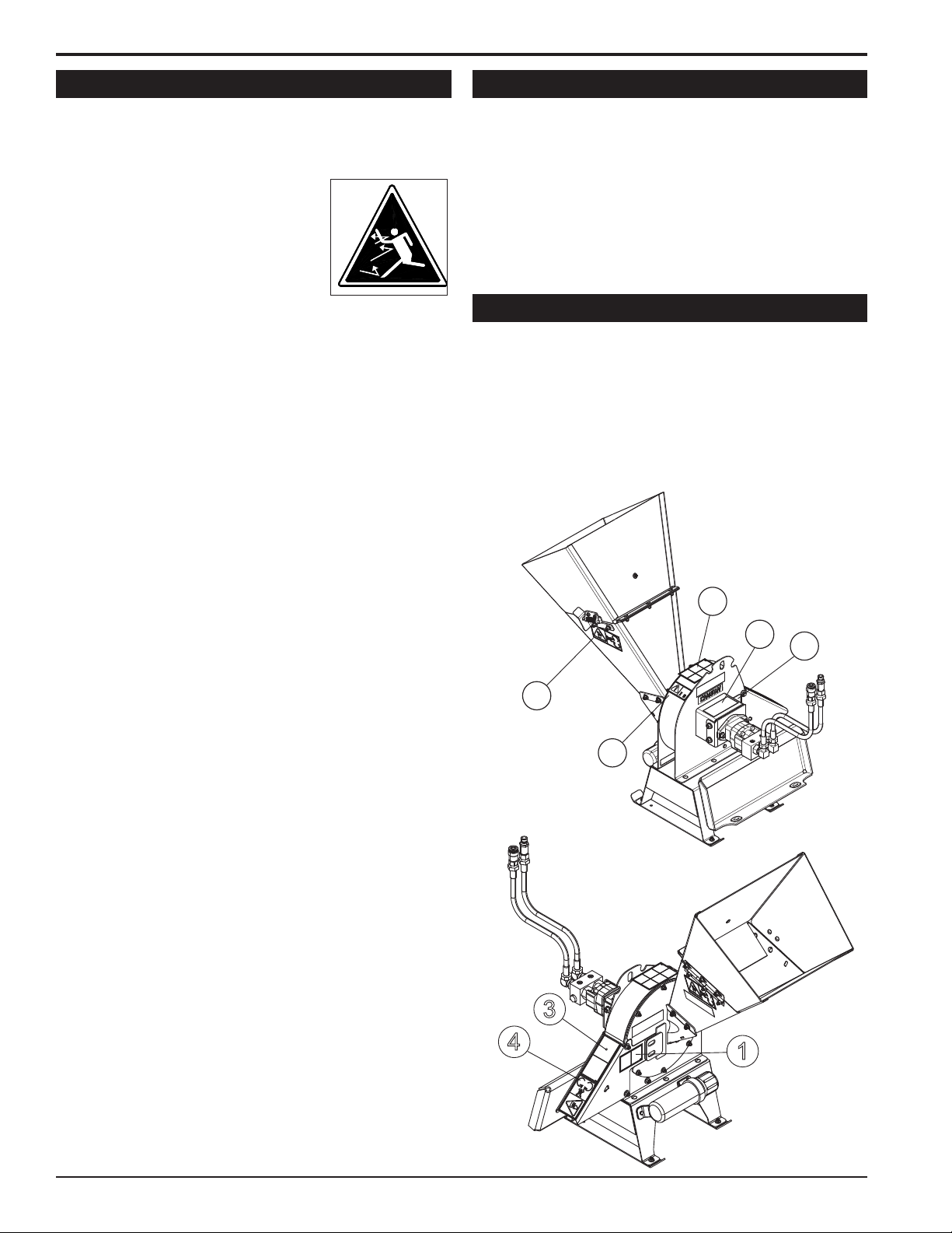
1.5 SAFETY DECAL LOCATIONS
The numbers below correspond to the decals in Section
1.6. Familiarize yourself with all of the safety and
operational decals on the machine and the associated
hazards. See the engine owner’s manual or contact the
engine manufacturer for engine safety instructions and
decals. Make certain that all safety and operating decals
on this machine are kept clean and in good condition.
Decals that need replacement must be applied to their
original locations.
2
7
6
4
5
3
4
1
2 4.5 INCH HYDRAULIC CHIPPER
Page 7
SAFETY
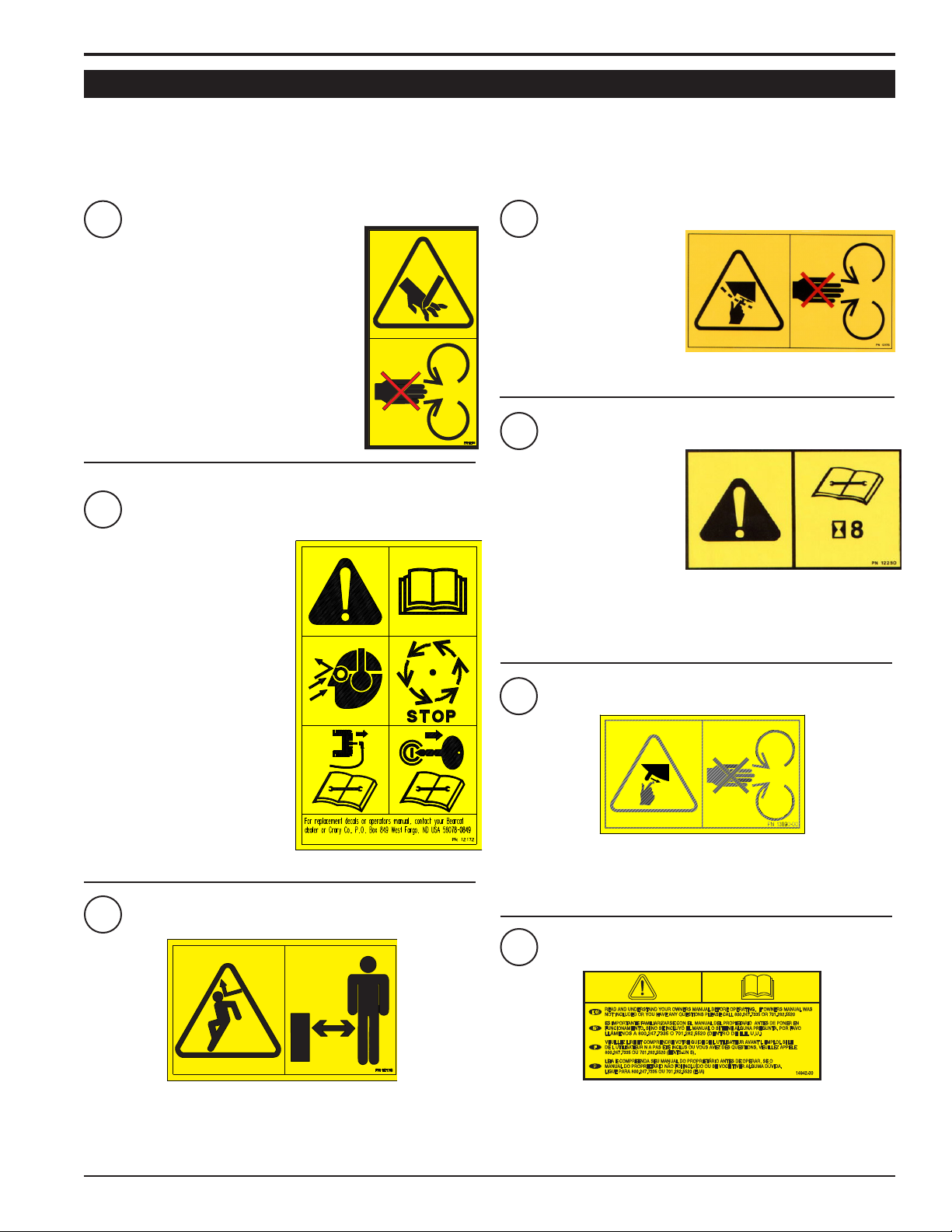
1.6 SAFETY DECALS
See Section 1.5 for decal locations. Familiarize yourself with all of the safety and operating decals on the machine
and the associated hazards. See the engine owner’s manual or contact the engine manufacturer for engine safety
instructions and decals. Make certain that all safety and operational decals on this machine are kept clean and in good
condition. Decals that need replacement must be applied to their original locations.
P/N 12175
1
PN 12169
PN 12169
4
PN 12175
KEEP HANDS AND FEET OUT OF INLET AND
DISCHARGE OPENINGS WHILE MACHINE
IS OPERATING TO AVOID SERIOUS
PERSONAL INJURY. STOP AND ALLOW
MACHINE TO COME TO A COMPLETE STOP
BEFORE CLEARING OBSTRUCTIONS.
PN 12172
2
READ AND UNDERSTAND THIS
OWNER/OPERATORS MANUAL.
BE COMPLETELY FAMILIAR
WITH THE CONTROLS AND
THE PROPER USE OF THIS
EQUIPMENT
OBTAIN AND WEAR SAFETY
GLASSES AND USE HEARING
PROTECTION AT ALL TIMES
WHEN OPERATING THIS
MACHINE.
KEEP HANDS AND FEET OUT
OF INLET AND DISCHARGE
OPENINGS WHILE MACHINE
IS OPERATING TO AVOID
SERIOUS PERSONAL
INJURY. STOP AND ALLOW
MACHINE TO COME TO A
COMPLETE STOP BEFORE
CLEARING OBSTRUCTIONS.
5
CHECK BLADE BOLTS
FOR PROPER TORQUE
AFTER EVERY 8 HOURS
OF OPERATION. CHECK
BLADES AND ROTATE OR
RESHARPEN DAILY OR
AS REQUIRED TO KEEP
BLADES SHARP. REFER
TO OWNERS MANUAL
FOR INSTRUCTIONS. FAILURE TO DO SO MAY CAUSE POOR
PERFORMANCE, DAMAGE OR PERSONAL INJURY AND WILL VOID
THE MACHINE WARRANTY.
6
PN 12250
PN 13890-00
BEFORE INSPECTING OR
SERVICING ANY PART OF THIS
MACHINE, SHUT OFF POWER
SOURCE, DISCONNECT SPARK
PLUG WIRE FROM SPARK PLUG
AND MAKE SURE ALL MOVING
PARTS HAVE COME TO A
COMPLETE STOP.
PN 12173
PN 12173
3
DO NOT OPERATE THIS EQUIPMENT IN THE VICINITY OF
BYSTANDERS. DO NOT ALLOW CHILDREN TO OPERATE THIS
EQUIPMENT. ALWAYS STAND CLEAR OF DISCHARGE AREA WHEN
OPERATING THIS MACHINE. KEEP FACE AND BODY AWAY FROM
DISCHARGE AREAS.
KEEP HANDS AND FEET OUT OF INLET AND DISCHARGE
OPENINGS WHILE MACHINE IS OPERATING TO AVOID SERIOUS
PERSONAL INJURY. STOP AND ALLOW MACHINE TO COME TO A
COMPLETE STOP BEFORE CLEARING OBSTRUCTIONS.
7
PN 14942-00
PN 14942-00
READ AND UNDERSTAND YOU OWNERS MANUAL BEFORE
OPERATING. IF OWNERS MANUAL WAS NOT INCLUDED OR
YOU HAVE ANY QUESTIONS, PLEASE CALL 800.247.7335
OR 701.282.5520 (U.S.A.)
34.5 INCH HYDRAULIC CHIPPER
Page 8
2
Section
ASSEMBLY
WARNING
If any bolts or nuts are dropped in the machine, be
sure to remove them before starting the machine.
2.1 DISCHARGE ASSEMBLY
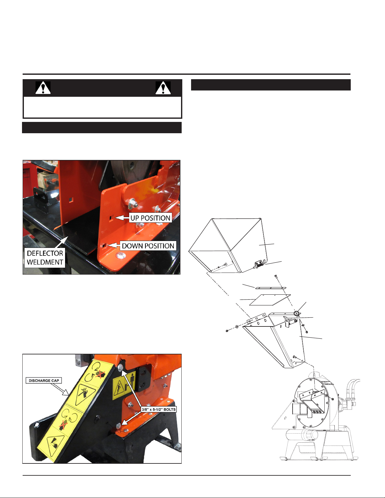
1. Move the chipper deflector weldment located inside the
chipper housing to the down position (Figure 2.1).
2.2 CHUTE ASSEMBLY
1. Attach the chipper chute to the chipper using four (4)
3/8" x 1" carriage bolts, 3/8" washers and 3/8" nuts. Use
two bolts on each side. Install with nuts on the outside.
2. Attach the chute extension to the chipper chute using
three (3) 3/8" x 1" carriage bolts, 3/8" washers and 3/8"
nuts. Install with nuts on the outside.
3. Use the lanyard to attach the chute extension to the
middle hole on the chipper chute.
4. Attach chute flap and flap strip to the chipper chute
as shown below with the three (3) 5/16 x 1" carriage
bolts, 5/16" washers, and 5/16" nylock nuts.
5. Latch the chute extension to the lock plate on the
chipper chute.
CHUTE EXTENSION
LATCH
Figure 2.1, Chipper deector weldment
2. Slide the discharge cap onto the chipper housingt
(Figure 2.2).
3. Insert two (2) 3/8" x 5-1/2" bolts into the bolt holes on
the chipper housing and tighten using 3/8" washers
and 3/8" nylock nuts.
FLAP STRIP
CHUTE FLAP
ATTACH
LANYARD
HERE
LOCK PLATE
CHIPPER
CHUTE
Figure 2.2, Discharge cap
4 4.5 INCH HYDRAULIC CHIPPER
Figure 2.3, Chipper chute extension
Page 9
3
FEATURES & CONTROLS
Section
Understanding how your machine works will help you achieve the best results when using your machine. The following
descriptions dene the features and controls of your machine.
CHUTE EXTENSION
CHIPPER CHUTE
Feed branches no larger than 4.5 inches in diameter
into the chipper chute.
CHIPPER DEFLECTOR
Chipped material exits out the chipper deector and
onto the ground. An optional chipper discharge tube
is also available (PN 74634-00).
CHUTE EXTENSION
An additional safety feature to keep the operator
from touching or being pulled into the chipper
blades. The extension should be unlatched and
rotated open on its hinge when transporting the
chipper.
FEMALE COUPLER/MALE COUPLER
Connect the couplers to the appropriate connectors
on the utility loader. Note that there is a zip tie
around the pressure hose.
MANUAL CONTAINER
Store your owner's manual in the manual
container.
FEMALE
COUPLER
(PRESSURE)
UTILITY
LOADER
MOUNT
CHIPPER CHUTE
MALE
COUPLER
UTILITY LOADER MOUNT
Use this mount to secure and transport the chipper
with a utility loader.
CHIPPER
DEFLECTOR
MANUAL
CONTAINER
54.5 INCH HYDRAULIC CHIPPER
Page 10
4
Section
OPERATION
As with any other piece of outdoor equipment, getting the
feel for how your machine operates and getting to know
the best techniques for particular jobs are important to
overall good performance.
CHIPPING OPERATION
The chipping operation takes place on the front of the
machine, where hardened steel chipper blades are
mounted on a rotating disk assembly. Material fed into the
chipper chute is sliced into small chips and propelled out
through the chipper deector .
WARNING
Move machine to a clear, level area outdoors before
starting. Do not operate in the vicinity of bystanders.
Make sure cutting chamber is empty before starting.
WARNING
Before operating your machine, be sure you read
and understand all safety, controls and operating
instructions in this owner's manual and on your
machine. Failure to follow these instructions can result
in serious injury or property damage.
4.2 MOUNTING THE CHIPPER TO A UTILITY LOADER
Consult the owner's manual for your utility loader
before mounting the chipper!
1. Position the chipper on a level surface.
2. Ensure that the mount plates are free of dirt or
debris.
3. Start the engine on the utility loader.
4. Direct the loader mount plate into the upper lip of the
chipper receiver plate.
5. Raise the loader arms while tilting back the mount
plate.
6. Stop the engine.
7. Engage loader pins to ensure the chipper is securely
mounted.
IMPORTANT
If the pins do not rotate to the engaged position, the
mount plate is not fully aligned with the holes in the
chipper receiver plate. Check the chipper plate and
clean it if necessary.
WARNING
If your loader creates back pressure greater than 250
psi, a case drain will have to be added to prevent
damage to the seal on the chipper disk motor. Contact
your dealer for more information.
4.1 RECOMMENDED HYDRAULIC FLOW RATES
HYDRAULIC FLOW RATES
MINIMUM FLOW RATE 10 GAL/MIN
MAXIMUM FLOW RATE 14 GAL/MIN
STANDARD HYDRAUILIC
PRESSURE
3000 PSI
WARNING
Exceeding the recommended ow rates can cause
severe damage and void the chipper warranty!
4.3 REMOVING THE CHIPPER FROM A UTILITY LOADER
1. Lower the chipper to the shipping pallet or base of
similar size. (30” x 50”)
2. Stop the engine.
3. Disengage the pins.
4. Relieve pressure on the hydraulic couplers (see your
owner’s manual).
5. Rotate the ball sleeve so the grooves are aligned with
the pins in the female coupler.
6. Retract the sleeve on the female coupler until the
couplers disconnect.
7. Repeat for the male hose.
8. Attach the chipper to the pallet using the four holes
located in the skids of the chipper base.
9. Start the engine, tilt the mount plate forward, and back
the loader away from the chipper.
6 4.5 INCH HYDRAULIC CHIPPER
Page 11

OPERATION
4.4 CONNECTING COUPLERS
WARNING
Hydraulic lines may be under pressure due to testing
done at the factory.
Consult the owner's manual for your utility loader
before mounting the chipper!
The chipper is equipped to attach to ush face couplers.
The chipper is shipped with -10 size hydraulic couplers
tted on the hoses. If your utility loader is tted with
anything other than -10 sized ush face couplers on the
main lines, you must replace the couplers supplied with
the chipper.
A tie wrap is used to indicate the pressure line. Be
sure to connect the hydraulic hoses to the proper ports.
TO CONNECT:
1. Stop the engine on the utility loader.
2. Remove dirt and debris from the surface of the couplers.
3. Visually check the couplers for damage; replace if
damage is found.
4. Relieve the hydraulic pressure in the utility loader (see
your owner's manual).
5. Push the chipper male coupler into the loader female
coupler. Full connection is made when the ball release
sleeve slides forward on the
female coupler.
WARNING
Handle pressurized hydraulic uid carefully. Escaping
pressurized hydraulic uid may penetrate your skin
causing serious injury. This uid may also be hot
enough to burn. Serious infection or reactions can
develop if immediate proper medical treatment is not
administered.
4.5 STARTING THE CHIPPER
Running the utility loader chipper is a one- or two-person
operation. If the loader requires an operator in the
driveseat, two people are needed. The chipper engages
with the hydraulics of the utility loader.
1. Set parking brake.
2. Engage the hydraulics of the utility loader to supply
power to the unit. The chipper will start to spin.
3. Bring the unit up to speed.
4. The chipper is ready to chip.
4.6 STOPPING THE CHIPPER
Slow down the engine of the utility loader to idle and after
several seconds disengage the utility loader hydraulics.
6. Turn the sleeve so that it is
rotated away from the locking
pin to prevent accidental
disconnection.
7. Push the chipper female
coupler into the loader male
coupler.
TO DISCONNECT:
1. Lower the chipper to the
ground.
2. Stop the engine.
3. Relieve pressure on the
hydraulic couplers (see your
owner's manual).
4. Rotate the ball sleeve so the
grooves are aligned with the
pins in the female coupler.
5. Retract the sleeve on the
female coupler until the
couplers disconnect.
6. Repeat for the male hose.
74.5 INCH HYDRAULIC CHIPPER
Page 12

OPERATION
4.7 OPERATING THE CHIPPER
CAUTION
Obtain and wear safety glasses at all times when
operating the machine.
Do not wear loose fitting clothing.
The operator should always wear heavy boots, gloves,
pants and a long-sleeved shirt.
Use common sense and practice safety to protect
yourself from branches, sharp objects, and other
harmful objects.
WARNING
Never lean over the chipper chute to push objects into the
cutting device. Use a push stick or brush paddle.
Never use shovels or forks to feed brush. They can
cause extensive damage if they contact the blades.
In addition, metal pieces can be ejected from the
chipper chute and cause serious injury or death.
Never feed brush into the chute with your feet.
Never use hands or feet to clear materials that build up in
the chute.
WARNING
Read and follow all safety instructions in this manual.
Failure to operate the machine in accordance with
the safety instructions MAY RESULT IN PERSONAL
INJURY!
The machine chips a variety of materials into a more
readily decomposed or handled condition. The following
guidelines will help you get started.
1. Run unit at full operating speed before starting to
chip material.
2. Limbs fed in to the chipper chute must be 4.5 inches
(11.4 cm) in diameter or less. Trim side branches that
cannot be bent enough to feed into the chipper chute.
Hold small diameter branches together in a bundle and
feed in simultaneously.
3. Exclude pieces of metal, rocks, bottles, cans, and
other foreign objects when feeding material into the
machine.
4. Feed brush from the side of the chipper chute, rather
than from the front. Step aside to avoid being hit by the
brush moving into the chipper.
5. Place limb, butt end first, into the chipper chute
until it contacts the chipper blades. The actual feed
rate of the limb into the chipper will depend on the type
of material fed and sharpness of the cutting blades.
6. If the engine slows to where it may stall, stop feeding
material and allow the engine to recover. Feed material
more evenly.
7. If the chipper jams, remove the branch and rotate it
before reinserting it into the chute. Alternately insert
and retract the limb or insert continuously at a rate that
will not kill the engine.
8. Alternate greener material with dry material to
lubricate the chipping blades for longer life and better
performance. Chipping dead, dry material will create
heat and dull the chipping blades quickly.
9. Sharpen the chipping blades periodically. Check
the sharpness of the blades every 5-15 hours. Refer
to the Service and Maintenance section for sharpening
instructions.
10. Do not drive the utility loader while chipping.
To prevent personal injury or property damage: shut
off engine and make sure that all moving parts have
come to a complete stop before, servicing, adjusting or
repairing. Disconnect the battery and remove ignition
key where applicable.
8 4.5 INCH HYDRAULIC CHIPPER
WARNING
Page 13
5
Section
SERVICE & MAINTENANCE
5.1 MAINTENANCE SCHEDULE
The items listed in this service and maintenance schedule
are to be checked, and if necessary, corrective action
taken. This schedule is designed for units operating under
normal conditions. If the unit is operating in adverse or
severe conditions, it may be necessary for the items to be
checked and serviced more frequently.
SEE ENGINE OWNER’S MANUAL FOR FURTHER
ENGINE MAINTENANCE AND TROUBLESHOOTING
INFORMATION.
SERVICE AND MAINTENANCE SCHEDULE
COMPONENT MAINTENANCE REQUIRED
ALL INTERNAL AND EXTERNAL
NUTS AND BOLTS
CHIPPER ANVIL
CHECK TIGHTNESS
CHECK CLEARANCE AND RE-TORQUE TO
75 FT-LBS. (1)
WARNING
To prevent personal injury or property damage: shut
off engine and make sure that all moving parts have
come to a complete stop before, servicing, adjusting or
repairing. Disconnect the battery and remove ignition
key where applicable.
FREQUENCY
BEFORE EACH
USE
EVERY 8
HOURS
EVERY 50
HOURS
CHIPPER BLADES
ENTIRE MACHINE CLEAN
GREASE ZERKS LUBE
(1) PERFORM MORE FREQUENTLY WHEN CHIPPING DRY OR DIRTY WOOD.
As the Limited Warranty states, failure by the Owner to perform normal maintenance will void the machine’s warranty. The aggressive,
high-speed nature of chipping REQUIRES THE OWNER TO PERFORM THE ABOVE LISTED NORMAL MAINTENANCE. Special consideration to maintain and re-torque the CHIPPER ANVIL, CHIPPER BLADES, AND ALL INTERNAL AND EXTERNAL NUTS AND BOLTS is the
sole responsibility of the Owner. Failure by the Owner to do so shall be cause for denial of warranty.
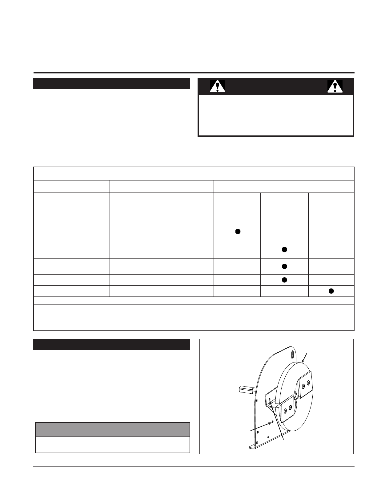
5.2 INSTALLING THE DISK LOCK
When working on the disk assembly, use the lock
mechanism at all times (Figure 5.1). Follow the steps below
to install the disk lock:
1. Rotate the disk until the hole on the paddle is aligned
with the hole on the chipper housing (Figure 5.1).
2. Install a punch or screwdriver into the holes.
One of the 3/8" x 5-1/2" bolts from the chipper deflector
can also be used to lock the disk.
CHECK SHARPNESS AND RE-TORQUE TO
120 FT-LBS. (1)
NOTE
CHIPPER
DISK
DISK LOCK
HOLE
MATCHING HOLE
ON DISK PADDLE
Figure 5.1 Disk lock
94.5 INCH HYDRAULIC CHIPPER
Page 14

SERVICE & MAINTENANCE
BEFORE INSPECTING OR SERVICING ANY PART OF THIS MACHINE, SHUT OFF POWER SOURCE,
AND MAKE SURE ALL MOVING PARTS HAVE COME TO A COMPLETE STOP.
WARNING
5.3 CHIPPER BLADE MAINTENANCE
The chipper blades will eventually become dull, making
chipping difcult and adding extra strain on the machine.
CHECK THE SHARPNESS OF THE BLADES EVERY
5 - 15 HOURS OF OPERATION AND SHARPEN AS
NEEDED.
Your blades need to be sharpened if:
• Machine vibrates severely when material is fed into the
chipper.
• Small diameter branches do not self-feed.
• Chips discharge unevenly or have stringy tails,
especially when chipping green branches.
Before you sharpen the chipping blades, check for
permanent damage. Replace the blade if:
• There are cracks, broken corners or nicks greater than
1/8" (see below).
CRACK
GREATER
THAN 1/8”
BROKEN
CORNER
• The base of the cutting edge is worn or has been resharpened so that it no longer extends past the chipping
slot (see below).
CHIPPER
DISC
CHIPPING
SLOT
NEW
BLADE
CHIPPER
DISC
BLADE IS
TOO SHORT,
MUST BE
REPLACED
NICK GREATER
THAN 1/8”
CHIPPING
SLOT
5.4 REMOVING THE BLADES
1. Remove the chipper deflector from the chipper housing.
2. Rotate the disk until a blade is accessible and install
the disk lock (Section 5.2).
3. Remove the two hex bolts holding the blade to the
disk.
4. To access the remaining blade, remove the punch or
screwdriver, reposition the disk, and return the punch
or screwdriver to the disk lock hole.
5. Repeat step 2 for the remaining blade.
6. Inspect blades to see if cracks or nicks are visible (see
Section 5.3).
5.5 SHARPENING THE BLADES
The blades can be ground on a bench grinder or by a
professional.
1. Never sharpen or grind the mounting surfaces of the
blades. This will cause the edge to roll and the blade will
be damaged, resulting in poor chipping performance.
2. Regrind the angled edge of the chipping blades to 45
degrees (see below). Make sure some type of fixture is
used to correctly hold the blade at the proper angle.
3. Be careful when grinding so that the blade does not
become overheated and change color. This will remove
the heat-treated properties.
4. Use short grinding times and cool with water or some
type of liquid coolant.
5. Remove an equal amount off each blade to maintain
rotor balance.
6. Small imperfections such as nicks and burrs on the flat
side of the blade will not affect the chipping performance
of the machine.
7. For blades that have been repeatedly sharpened,
ensure that the sharpened surface extends past the
chipping slot opening. If it does not extend past the
opening, the blades should be replaced.
MOUNTING SURFACE
(DO NOT GRIND)
SHARPENED
SURFACE
45°
.25
WARNING
The chipping blades are sharp!! Use care when
working on the machine to avoid injury.
10 4.5 INCH HYDRAULIC CHIPPER
SHARPENED
SURFACE
MOUNTING SURFACE
(DO NOT GRIND)
Page 15

WARNING
50
h
BEFORE INSPECTING OR SERVICING ANY PART OF THIS MACHINE, SHUT OFF POWER SOURCE,
AND MAKE SURE ALL MOVING PARTS HAVE COME TO A COMPLETE STOP.
5.6 INSTALLING THE BLADES
1. Lock disk assembly (Section 5.2).
2. Secure a blade to the disk with two hex bolts. Torque
to 120 Ft.-lb. Repeat for the remaining blades.
3. Reinstall the chipper deflector.
5.7 SETTING BLADE CLEARANCE
The chipping blades should clear the chipping anvil, located
directly under the chipper chute, by 1/16".
Removing the chipper chute is not required for setting the
chipping blade clearance. However, removing the chipper
chute can provide better access for measuring the blade
clearance. To adjust the blade clearance, proceed as
follows:
1. Rotate the disk until a chipping blade is even with the
chipping anvil.
2. Measure the amount of clearance between the
chipping blade and chipper anvil from inside the
chipper housing. The distance between the chipping
blade and the anvil should be 1/16" (Figure 5.2).
SERVICE & MAINTENANCE
Figure 5.2, Chipper blade and anvil clearance
5.8 LUBRICATION
Lubricate the machine periodically with a lithium-based
grease. Extreme working conditions will require more
frequent greasing. Grease the zerk on the bearing every
50 hours of operating time.
3. Adjust the anvil by loosening the 5/16" x 5/8" bolts
holding the anvil to the disk cover and sliding the anvil
inward or outward until the desired measurement is
achieved.
4. Torque the bolts to 17 Ft-lbs.
5. Rotate the rotor to ensure the remaining blade clears
the anvil by 1/16".
6. If the chipper chute was removed, reinstall it.
WARNING
It is important to ensure that the minimum gap between
the chipping anvil and ALL chipping blades is 1/16". All
chipping blades should be rotated until even with the
chipping anvil and then measured. Failure to do so can
result in the chipping blades striking the chipping anvil,
causing serious injury or death.
NOTE
If the chipping anvil edge is damaged or worn unevenly,
remove the three bolts and washers holding the anvil
to the disk cover and use one of the other three edges.
Adjust for correct measurement.
Figure 5.3, Grease the zerk periodically
IMPORTANT
Polyurea and lithium-based greases are not compatible.
Mixing the two grease types may lead to premature
failure.
NOTE
Do not over grease bearings. Overlling can lead to
excessive heat and/or unseating of the seals. Add
grease slowly and under light pressure. Whenever
possible, rotate bearing slowly while lubricating.
114.5 INCH HYDRAULIC CHIPPER
Page 16

SERVICE & MAINTENANCE
BEFORE INSPECTING OR SERVICING ANY PART OF THIS MACHINE, SHUT OFF POWER SOURCE,
AND MAKE SURE ALL MOVING PARTS HAVE COME TO A COMPLETE STOP.
WARNING
5.9 REPLACING ROTOR BEARINGS
REMOVING THE OLD ROTOR BEARING
1. Unhook hydraulic hoses from the utility loader.
2. Unscrew the two screws from the split coupler (the bolts
are located underneath the coupler).
3. Remove the four bolts from the base weldment.
4. Slide out the hydraulic pump assembly as an entire
unit.
5. Remove the split coupler.
6. Remove the snap ring located right before the
bearing.
7. Remove the 1/2" nuts from the bearing.
8. Take off bearing and replace.
See Figures 5.4 and 5.5.
INSTALLING THE NEW ROTOR BEARING
1. Replace the 1/2" nuts to secure the new bearing to the
motor mount plate.
2. Replace the snap ring.
3. If the unit comes with a shim behind the bearing,
reinstall it.
4. Replace the hydraulic pump assembly by replacing the
screws and bolts. Replace the 1/2" nuts.
5. Reattach the hydraulic hoses to the utility loader.
NOTE
When reinstalling the new bearing, make sure the
grease zerk is facing the bottom of the housing.
5.10 CLEARING A PLUGGED DISK
1. Remove the chipper deflector (see Fig. 5.6).
2. Remove debris, taking care to avoid the chipper
blades, which can be extremely sharp.
Figure 5.4 - Unscrewing the two screws from the split coupler
3. Once debris is removed, replace the chipper deflector.
Figure 5.6 - Location of chipper deector
Figure 5.5 - Disassembly of hydraulic pump, coupler, and snap ring to
get to the bearing.
12 4.5 INCH HYDRAULIC CHIPPER
Page 17

6
TROUBLESHOOTING
Section
Before performing any of the corrections in this troubleshooting chart, refer to the appropriate information contained in
this manual for the correct safety precautions and operating or maintenance procedures. Contact your dealer or the
factory for service problems with the machine
PROBLEM POSSIBLE CAUSES REMEDY
Obstructed discharge. Use branch or similar object to clear discharge.
Rotor stalls or stops.
Chipper does not chip.
Hard to feed chipper; requires
excessive
power to chip.
Material from chipper wraps
around rotor shaft
Excessive vibration while
running.
Plugged rotor. Clear rotor. Feed material more evenly.
Feeding material that is too large. Reduce size of material being fed into chipper.
Dull chipper blades. Rotate or sharpen blades.
Attempting to feed branches that are too
large.
Broken or missing chipper blades Replace blade.
Dull chipper blades. Reverse or sharpen blades.
Obstructed discharge. Use branch or similar object to clear discharge.
Improper blade clearance.
Stringy, green material bypasses chipper
blades.
Dull chipper blades. Sharpen blades.
Improper blade clearance.
Rotor out of balance.
Chipper blade to anvil clearance is
incorrect.
Limit branch size to 4.5 inches in diameter.
Adjust clearance between chipper anvil and
chipper blades.
Rotate branch or material when feeding to cut
completely.
Adjust clearance between anvil and chipper
blades.
Inspect rotor for broken or missing chipper blades;
replace if needed. Check rotor to see if it wobbles.
Check to see if rotor is assembled correctly.
Set chipper blade/anvil clearance to recommended
distance (1/16”).
Rotor will not turn.
Chipper does not seat properly
on the utility loader
Obstructed discharge. Use branch or similar object to clear discharge.
Plugged rotor. Clear rotor. Feed material more evenly.
Wedges are not fully extended Retract wedges.
Mud, dirt or stones are lodged between the
chipper and the utility loader.
Remove debris from between the chipper and the
utility loader.
134.5 INCH HYDRAULIC CHIPPER
Page 18

7
SPECIFICATIONS
Section
7.1 SPECIFICATIONS
CH450H
DESCRIPTION ENGLISH METRIC
OVERALL SIZE 39.8" X 36.6" X 42.9" 101 X 93 X 109 CM
OVERALL WEIGHT 359 LBS. 163 KG
MAX CHIPPER CAPACITY 4.5" 11.4 cm
CHIPPER BLADES 2 REVERSIBLE (5" X 4" X 3/8") 2 REVERSIBLE (12.7 x 10.2 x .95 CM)
CHIPPING ANVIL 4.94" X 1.75" X .375 " 12.5 X 4.4 X 0.95 CM
DISC SPEED 2400 RPM 2400 RPM
DISC SIZE 14" DIA. X 1" 35.5 CM x 2.5 CM
DISC WEIGHT 49 LBS. 22.2 KG
DISCHARGE TUBE SIZE
DRIVE TYPE HYDRAULIC HYDRAULIC
MINIMUM HYDRAULIC
FLOW RATE
MAXIMUM HYDRAULIC
FLOW RATE
HYDRAULIC PRESSURE 3000 PSI 20,680 KPa
4.5" X 9" (STANDARD) 11 x 23 CM (STANDARD)
4.5" X 4.5" (OPTIONAL) 11 x 11 CM (OPTIONAL)
10 GAL/MIN 37.8 LITERS/MIN
14 GAL/MIN 53.0 LITERS/ MIN
14 4.5 INCH HYDRAULIC CHIPPER
Page 19

SPECIFICATIONS
7.2 BOLT TORQUE
The tables below are for reference purposes only and their use by anyone is entirely voluntary, unless otherwise noted.
Reliance on their content for any purpose is at the sole risk of that person and any loss or damage resulting from the
use of this information is the responsibility of that person.
SAE
SAE - 2
SAE - 5
SAE - 8
BOLT DIAMETER
Grade
and
Head
A
Markings
ENGLISH
BOLT DIAMETER (A)
1/4” 7.5 5.5 11 8 16 12
5/16” 15 11 23 17 34 25
3/8” 27 20 41 30 61 45
7/16” 41 30 68 50 95 70
1/2” 68 50 102 75 149 110
9/16” 97 70 149 11 0 203 150
5/8” 122 90 203 150 312 230
3/4” 217 160 353 260 515 380
7/8” 230 170 542 400 814 600
1” 298 220 786 580 1220 900
1-1/8” 407 300 1085 800 1736 1280
1-1/4” 570 420 2631 1940 2468 1820
SAE 2 SAE 5 SAE 8
N.m Ft-lb. N.m Ft-lb. N.m Ft-lb.
BOLT TORQUE *
METRIC
Grade
and
Head
Markings
4.8
4.8
8.8
8.8 10.9
10.9
12.9
12.9
BOLT DIAMETER
A
METRIC
BOLT DIAMETER
(A)
M3 0.5 0.4 - - - - - -
M4 3 2.2 - - - - - -
M5 5 4 - - - - - -
M6 6 4.5 11 8.5 17 12 19 14.5
M8 15 11 28 20 40 30 47 35
M10 29 21 55 40 80 60 95 70
M12 50 37 95 70 140 105 165 120
M14 80 60 150 110 225 165 260 190
M16 125 92 240 175 350 255 400 300
M18 175 125 330 250 475 350 560 410
M20 240 180 475 350 675 500 800 580
M22 330 250 650 475 925 675 1075 800
M24 425 310 825 600 1150 850 1350 1000
M27 625 450 1200 875 1700 1250 2000 1500
4.8 8.8 10.9 12.9
N.m Ft-lb. N.m Ft-lb. N.m Ft-lb. N.m Ft-lb.
* Torque value for bolts and capscrews are identified by their head markings.
Torque figures indicated above are valid for non-greased or non-oiled threads and heads unless otherwise specified. Therefore, do not
grease or oil bolts or capscrews unless otherwise specified in this manual. When using locking elements, increase torque values by 5%.
BOLT TORQUE *
154.5 INCH HYDRAULIC CHIPPER
Page 20

8
PARTS
Section
8.1 PARTS ORDERING INFORMATION 8.2 REPLACEMENTS PARTS
IF YOU NEED SERVICE OR PARTS FOR YOUR
MACHINE:
For service assistance, contact your nearest
authorized ECHO Bear Cat dealer or the factory. For parts,
contact your authorized ECHO Bear Cat dealer. Your ECHO
Bear Cat dealer will need to know the serial number of your
machine to provide the most efcient service.
See inside front cover for information on how to identify
and record the serial number for your machine.
IF YOU NEED ENGINE SERVICE OR PARTS:
For engine service or parts, contact your nearest
authorized engine dealer. Look in the yellow pages of
the phone book under "Engines-Gasoline" for the name
of your nearest authorized engine dealer. An authorized
engine dealer can handle all parts, repairs and warranty
service concerning the engine.
8.3 BASE & HOUSING
15
11
20
2
Only genuine ECHO Bear Cat replacement parts should
be used to repair the machine. ECHO Bear Cat replacement parts are available from your ECHO Bear Cat Deal-
er. To obtain prompt, efcient service, remember to give
the dealer the correct part description and serial number
of the machine.
WHEN ORDERING PARTS FOR YOUR MACHINE,
PROVIDE THE FOLLOWING:
1. The SERIAL NUMBER of your machine.
2. The PART NUMBER of the part.
3. The PART DESCRIPTION.
4. The QUANTITY needed.
WARNING
Use only genuine replacement parts that meet all the
latest requirements. Replacement parts manufactured
by others could present safety hazards, even though
they may t on this unit.
1
4
8
19
8
9
21
17
6
11
8
25
10
5
18
14
12
3
16 4.5 INCH HYDRAULIC CHIPPER
Page 21

8.3 BASE & HOUSING
7
8
11
5
12
13
16
22
23
24
ITEM PART NUMBER DESCIRPTION
1 12172 DECAL, OPERATING INSTRUCTIONS ISO
2 12250 DECAL, MAINTENANCE ISO
3 13890-00 DECAL, DANGER
4 14942-00 DECAL, MUTILINGUAL MANUAL
5 15031 WASHER, 3/8 FLAT ZP
6 15057 BOLT, 3/8 X 1 CRG GR5 NC ZP
7 15205 BOLT, 3/8 X 5 HEX HD GR5 ZP
8 15250 WASHER, 5/16 FLAT ZP
9 15300 BOLT, 5/16 X 5/8 HEX HD GR5 ZP
10 15349 BOLT, 5/16 X 7/8 CRG GR5 NC ZP
11 15356 NUT, 5/16 NE NYLOCK ZP
12 15388 NUT, 3/8 NE NYLOCK ZP
13 15396 BOLT, 5/16 X 7/8 HEX HD NC GR5 ZP
14 16155 DECAL, SERIAL NUMBER
15 17913 DECAL, ECHO BEARCAT 6.82 X 1.90
16 18008-00 CONTAINER, MANUAL
17 31890-00 DECAL, ATLANTIC BRIDGE LTD INFO
18 31912-00 DECAL, CH450H INFORMATION
19 36175-00 DECAL, MODEL CH450H
20
21 74529-00 ANVIL, CHIPPER
22 74571-12 WELDMENT, CHIP DEFLECTOR
23
24
25
WELDMENT, DISK COVER (WAS 77721-35, RELACED AND SUPERSEDED. FOR
SERVICE ORDER PN 70026-00)
WELDMENT, CHIPPER HOUSING (WAS 75911-35, REPLACED AND SUPERSEDED.
FOR SERVICE ORDER KIT #77781-00)
WELDMENT, BASE (WAS 75915-12, OBSOLETE AND REPLACED. FOR SERVICE
ORDER KIT #70405-00)
PLATE, BASE SKID (WAS 75916-12, OBSOLETE AND REPLACED. FOR SERVICE
ORDER KIT #70405-00)
PLATE, ACCESS (WAS 75919-35, REMOVED)
PARTS
174.5 INCH HYDRAULIC CHIPPER
Page 22

PARTS
8.4 ROTOR & HYDRAULICS
25
2
24
10
11
5
1
14
17
3
7
3
9
4
6
8
23
16
5
4
3
12
19
18
18 4.5 INCH HYDRAULIC CHIPPER
20
21
13
15
Page 23

8.4 ROTOR & HYDRAULICS
ITEM PART NUMBER DESCIRPTION
1 0103-0112-00 BOLT, 1/2 X 1 CRG GR5 ZP
2 14768-00 SNAP RING, 1-1/4 EXT. HEAVY DUTY
3 15049 NUT, 1/2 CENTERLOCK GRB ZP
4 15097 WASHER, 1/2 SAE FLAT ZP
5 15157 BOLT, 1/2 X 1-1/2 CRG GR5 ZP
6 15180 SET SCREW, 1/4 X 5/8 SQ HD
7 15282 BOLT, 5/16 X 1-1/2 HEX HD GR5 ZP
8 15356 NUT, 5/16 NE NYLOCK ZP
9 15365 KEY, 1/4 SQUARE X 1 LONG
10 15770-00 WASHER, 5/8 SAE HARDENED
11 15833-00 BOLT, M16 X 2.0 X 30 HEX HD W/PATCH
12 16330 ADAPTER, -10 MORING / -10 MJIC
13 16638 ADAPTER, -10 MORING / -10 MJIC 90 DEG.
14 16682 BEARING, 1-1/4" DIA 2 BOLT FLANGE
15 36181-00 HOSE, .63 X 46" -10 FMJIC SW / -10FMJIC SW
16 36182-00 MOTOR, .93 CU. IN. HYD
17 36183-00 COUPLER, 7/8 SPLIT
18 36184-00 COUPLER, MALE PRESSURE CONNECT
19 36185-00 COUPLER, FEMALE CONNECT
20 36658-00 ADAPTER, -16 MORING / -10 FMORING
21 36669-00 MANIFOLD, OVERRUN AND REVERSE CHECK -10
SHIM, BEARING (WAS 75550-00, REMOVED)
22 75912-12 PLATE, MOTOR MOUNT
23
24
76295-00 KIT, 4-1/2 CHIPPER BLADE KIT
WELDMENT, 4-1/2 HYD DISK (WAS 32840-00, REPLACED AND SUPERSEDED.
FOR SERVICE ORDER PN 32964-00)
BLADE, BIG CHIPPER (FOR SERVICE ORDER REPLACEMENT BLADE KIT
#76295-00)
PARTS
194.5 INCH HYDRAULIC CHIPPER
Page 24

PARTS
8.5 ATTACHMENTS
18
17
13
21
6
8
16
11
7
9
19
6
4
12
5
11
11
5
20
6
1
5
15
9
7
10
14
9
6
11
22
3
4
2
5
11
20 4.5 INCH HYDRAULIC CHIPPER
Page 25

8.5 ATTACHMENTS
ITEM PART NUMBER DESCIRPTION
1 0103-0848-00 BOLT, 3/8 X 5-1/2 HEX HD GR5 ZP
2 12169 DECAL, KNIFE ACCESS ISO
3 12173 DECAL, DISCHARGE ISO
4 12175 DECAL, BLADE DANGER ISO
5 15031 WASHER, 3/8 FLAT ZP
6 15057 BOLT, 3/8 X 1 CRG GR5 NC ZP
7 15250 WASHER, 5/16 FLAT ZP
8 15301 BOLT, 5/16 X 1 CRG GR5 ZP
9 15356 NUT, 5/16 NE NYLOCK ZP
10 15367 BOLT, 5/16 X 3/4 CRG GR5 NC ZP
11 15388 NUT, 3/8 NE NYLOCK ZP
12 17913 DECAL, ECHO BEARCAT 6.82 X 1.90
13 14771-00 FLAP, CHIPPER CHUTE
14 14971-00 LATCH, RH HINGE
15 18292-00 LANYARD, STEEL W/PVC 1/8" X 20"
16 31391-00 DECAL, CHIP IT
17 73918-35 WELDMENT, HOPPER
18 74311-35 WELDMENT, HOPPER EXT 4-1/2 PTO
19 74354-12 WELDMENT, 4-1/2" EXTENSION TRAY
20 74355-12 HINGE, CHUTE EXT
21 74608-12 STRIP, FLAP RETAINER
22 74670-00 ASSEMBLY, DISCHARGE CAP, SERVICE PART (INCLUDES ITEMS 2-4)
214.5 INCH HYDRAULIC CHIPPER
Page 26

8.6 SERVICE PARTS & OPTIONS
SERVICE PARTS AND OPTIONS
PART NUMBER DESCRIPTION
76295-00 CHIPPER BLADE KIT
74634-00 OPTIONAL 4.5" SQUARE DISCHARGE CHUTE
CHIPPER BLADE KIT, 76295-00
Page 27

ECHO BEAR CAT
www.bearcatproducts.com
237 NW 12th Street, West Fargo, ND 58078-0849
Phone: 701.282.5520 • Toll Free: 888.645.4520 • Fax: 701.282.9522
E-mail: service@bearcatproducts.com • sales@bearcatproducts.com
 Loading...