

Page 1

12 INCH CHIPPER
CH123DH (7812086) - 3 L DIESEL,
HYDRAULIC FEED
ENGLISH ESPAÑOL FRANÇAIS
Manual PN: 18130-00
Rev. 040110
Companion to 18131-00
VIN Range: 5VJAA00177W000395 - Current
OWNER'S MANUAL
Page 2

Before You Begin
DEAR ECHO BEAR CAT CUSTOMER
Thank you for purchasing a ECHO Bear Cat product. The ECHO Bear Cat line is designed, tested, and manufactured
to give years of dependable performance. To keep your machine operating at peak effi ciency, it is necessary to adjust
it correctly and make regular inspections. The following pages will assist you in the operation and maintenance of your
machine. Please read and understand this manual before operating your machine.
If you have any questions or comments about this manual, please call us toll-free at 1-800-247-7335.
If you have any questions or problems with your machine, please call or write your local authorized ECHO Bear Cat
Dealer.
This document is based on information available at the time of its publication. ECHO Bear Cat is continually making
improvements and developing new equipment. In doing so, we reserve the right to make changes or add improvements
to our product without obligation for equipment previously sold.
PLEASE SEND US YOUR WARRANTY CARD
A warranty card is included in your owner's kit packaged with your machine. Please take the time to fi ll in the information
requested on the card. When you send your completed card to us, we will register your machine and start your
coverage under our limited warranty.
FOR MACHINE SERVICE OR PARTS:
For service assistance, contact your nearest authorized
ECHO Bear Cat dealer or the factory. For parts, contact
your authorized dealer. The parts manual for your machine
is available at http://bearcatproducts.com/main/support/
index_html. Your dealer will need to know the identifi cation
number of your machine to provide the most effi cient
service. See below for information on how to identify and
record the identifi cation number for your machine.
FOR ENGINE SERVICE OR PARTS:
For engine service or parts, contact your nearest authorized
engine dealer. ECHO Bear Cat does not handle any parts,
repairs or warranties for engines.
IDENTIFICATION NUMBER LOCATION
Your machine will have either a serial number or vehicle
identifi cation number (VIN). VINs are located on the left
side of the trailer frame near the hitch. They are 17-digit
numbers of the format: 5VJAA001XXWXXXXXX. Serial
numbers are located on the machine body. They are
6-digit numbers.
Record your identifi cation number in the space provided
and on the warranty registration card.
ORDERING PARTS
Only genuine ECHO Bear Cat replacement parts should
be used to repair the machine. Replacement parts
manufactured by others could present safety hazards,
even though they may fi t on this machine. Replacement
parts are available from your ECHO Bear Cat dealer.
Provide the following when ordering parts:
The SERIAL NUMBER OR VIN of your machine.
The PART NUMBER of the part.
The PART DESCRIPTION.
The QUANTITY needed.
SERIAL NUMBER OR VIN
HOW TO CONTACT ECHO BEAR CAT
ADDRESS PHONE E-MAIL HOURS
237 NW 12th Street
P.O. Box 849
West Fargo, ND 58078
© 2010, CRARY INDUSTRIES, ALL RIGHTS RESERVED. PRODUCED AND PRINTED IN THE U.S.A.
800-247-7335
701-282-5520
FAX: 701-282-9522
opesales@crary.com
service@crary.com
Monday - Friday,
8 am to 5 pm
Central Time
Page 3

LIMITED WARRANTY
This warranty applies to all AG and Outdoor Power Equipment manufactured by Crary Industries.
Crary Industries warrants to the original owner each new Crary Industries product to be free from defects
in material and workmanship, under normal use and service. The warranty shall extend 1 year from date of
delivery for income producing (commercial) applications and 2 years from date of delivery for non-income
producing (consumer) use of the product. The product is warranted to the original owner as evidenced by a
completed warranty registration on file at Crary Industries. Replacement parts are warranted for (90) days
from date of installation.
THE WARRANTY REGISTRATION MUST BE COMPLETED AND RETURNED TO CRARY INDUSTRIES
WITHIN 10 DAYS OF DELIVERY OF THE PRODUCT TO THE ORIGINAL OWNER OR THE WARRANTY
WILL BE VOID.
In the event of a failure, return the product, at your cost, along with proof of purchase to the selling Crary
Industries dealer. Crary Industries will, at its option, repair or replace any parts found to be defective in material
or workmanship. Warranty on any repairs will not extend beyond the product warranty. Repair or attempted
repair by anyone other than a Crary Industries dealer as well as subsequent failure or damage that may occur
as a result of that work will not be paid under this warranty. Crary Industries does not warrant replacement
components not manufactured or sold by Crary Industries.
This warranty applies only to parts or components that are defective in material or workmanship. 1.
This warranty does not cover normal wear items including but not limited to bearings, belts, pulleys, filters 2.
and chipper knives.
This warranty does not cover normal maintenance, service or adjustments.3.
This warranty does not cover depreciation or damage due to misuse, negligence, accident or improper 4.
maintenance.
ENGLISH
This warranty does not cover damage due to improper setup, installation or adjustment.5.
This warranty does not cover damage due to unauthorized modifications of the product. 6.
Engines are warranted by the respective engine manufacturer and are not covered by this warranty.7.
Crary Industries is not liable for any property damage, personal injury or death resulting from the unauthorized
modification or alteration of a Crary product or from the owner’s failure to assemble, install, maintain or operate
the product in accordance with the provisions of the Owner’s manual.
Crary Industries is not liable for indirect, incidental or consequential damages or injuries including but not
limited to loss of crops, loss of profits, rental of substitute equipment or other commercial loss.
This warranty gives you specific legal rights. You may have other rights that may vary from area to area.
Crary Industries makes no warranties, representations or promises, expressed or implied as to the performance
of its products other than those set forth in this warranty. Neither the dealer nor any other person has any
authority to make any representations, warranties or promises on behalf of Crary Industries or to modify the
terms or limitations of this warranty in any way . Crary Industries, at its discretion, may periodically offer limited,
written enhancements to this warranty.
CRARY INDUSTRIES RESERVES THE RIGHT TO CHANGE THE DESIGN AND/OR SPECIFICATIONS
OF ITS PRODUCTS AT ANY TIME WITHOUT OBLIGATION TO PREVIOUS PURCHASERS OF ITS
PRODUCTS.
Page 4

TABLE OF CONTENTS
DESCRIPTION PAGE
SAFETY ..........................................................................................................1
1.1 SAFETY ALERT SYMBOL .............................................................................1
1.2 EMISSION INFORMATION ............................................................................1
1.3 BEFORE OPERATING ..................................................................................1
1.4 OPERATION SAFETY ...................................................................................2
1.5 FEED ROLLER SAFETY ...............................................................................3
1.6 MAINTENANCE & STORAGE SAFETY ........................................................3
1.7 TOWING SAFETY..........................................................................................3
1.8 BATTERY SAFETY ........................................................................................3
1.9 SAFETY DECALS ..........................................................................................4
1.10 SAFETY DECAL LOCATIONS ......................................................................5
ASSEMBLY .................................................................................................... 6
2.1 INSTALL A BATTERY .....................................................................................6
2.2 ADD MOTOR OIL ..........................................................................................6
2.3 FILL THE FUEL TANK ....................................................................................7
2.4 ADD COOLANT .............................................................................................7
2.5 ADD HYDRAULIC FLUID...............................................................................7
FEATURES & CONTROLS ............................................................................8
OPERATION .................................................................................................10
4.1 STARTING THE CHIPPER ..........................................................................10
4.2 STOPPING THE CHIPPER .........................................................................10
4.3 DIRECTING THE DISCHARGE CHUTE .....................................................10
4.4 OPERATING THE CHIPPER .......................................................................11
4.5 FEED ROLLER CONTROL BAR .................................................................11
4.6 RAISING THE FEED ROLLER ....................................................................12
4.7 FEED ROLLER SPEED CONTROL ............................................................12
4.8 RAISE THE KNIFE ACCESS COVER ..........................................................12
4.9 FEED CONTROLLER ..................................................................................13
SERVICE & MAINTENANCE .......................................................................14
5.1 SERVICE AND MAINTENANCE SCHEDULE .............................................14
5.2 CHIPPER BLADE MAINTENANCE .............................................................15
5.3 REMOVING THE BLADES ..........................................................................15
5.4 SHARPENING THE BLADES ......................................................................15
5.5 INSTALLING THE BLADES .........................................................................16
5.6 SETTING BLADE CLEARANCE ..................................................................16
5.7 REPLACING THE DRIVE BELT...................................................................17
5.8 CHECK/FILL COOLANT ..............................................................................17
5.9 CHANGE HYDRAULIC OIL FILTER ............................................................18
5.10 TRAILER SERVICE TIPS ...........................................................................18
5.11 CHECK HYDRAULIC FLUID .......................................................................18
5.12 LUBRICATION ............................................................................................18
5.13 REPLACING THE BEARINGS ....................................................................20
TROUBLESHOOTING .................................................................................22
SPECIFICA TIONS ........................................................................................23
7.1 BOLT TORQUE ............................................................................................24
7.2 KUBOTA ENGINE SAFETY SHUTDOWN AUX. CIRCUIT ..........................25
7.3 KUBOTA ENGINE SCHEMATIC ..................................................................26
iv
12 INCH CHIPPER
Page 5
1
Section
SAFETY
1.1 SAFETY ALERT SYMBOL
The Owner/Operator’s manual uses this symbol to alert
you of potential hazards. Whenever you see this symbol,
read and obey the safety message that follows it. Failure
to obey the safety message could result in personal injury ,
death or property damage.
DANGER
Indicates an imminently hazardous situation that, if not
avoided, will result in death or serious injury.
The engine on your power equipment, like most outdoor
power equipment, is an internal combustion engine that
burns gasoline or diesel fuel (hydrocarbons). Therefore,
your power equipment must be equipped with a spark
arrester muffl er in continuous effective working order. The
spark arrester must be attached to the engine exhaust
system in such a manner that fl ames or heat from the
system will not ignite fl ammable material.
Failure of the owner/operator of the equipment to comply
with this regulation is a misdemeanor under California law
and may also be a violation of other state and/or federal
regulations, laws, ordinances, or codes. Contact your
local fi re marshal or forest service for specifi c information
about which regulations apply in your area.
The standard muffl er installed on the engine is not equipped
with a spark arrester. One must be added before using
this machine in an area where a spark arrester is required
by law. Contact the local authorities if these laws apply to
you. See your authorized engine dealer for spark arrester
options.
ENGLISH
WARNING
Indicates a potentially hazardous situation that, if not
avoided, could result in death or serious injury.
CAUTION
Indicates a potentially hazardous situation that, if not
avoided, may result in minor or moderate injury.
1.2 EMISSION INFORMATION
Under California
Law and the laws of
several other states,
you are not permitted
to operate an internal
combustion engine using
hydrocarbon fuels on any
forest covered, brush
covered or grass covered
land or on land covered with grain, hay or other fl ammable
agricultural crops, without an engine spark arrester in
continuous effective working order.
1.3 BEFORE OPERATING
Read and understand this owner’s manual. Be 1.
completely familiar with the controls and the proper
use of this equipment.
Familiarize yourself with all of the safety and operating 2.
decals on this equipment and on any of its attachments
or accessories.
Keep safety decals clean and legible. Replace missing 3.
or illegible safety decals.
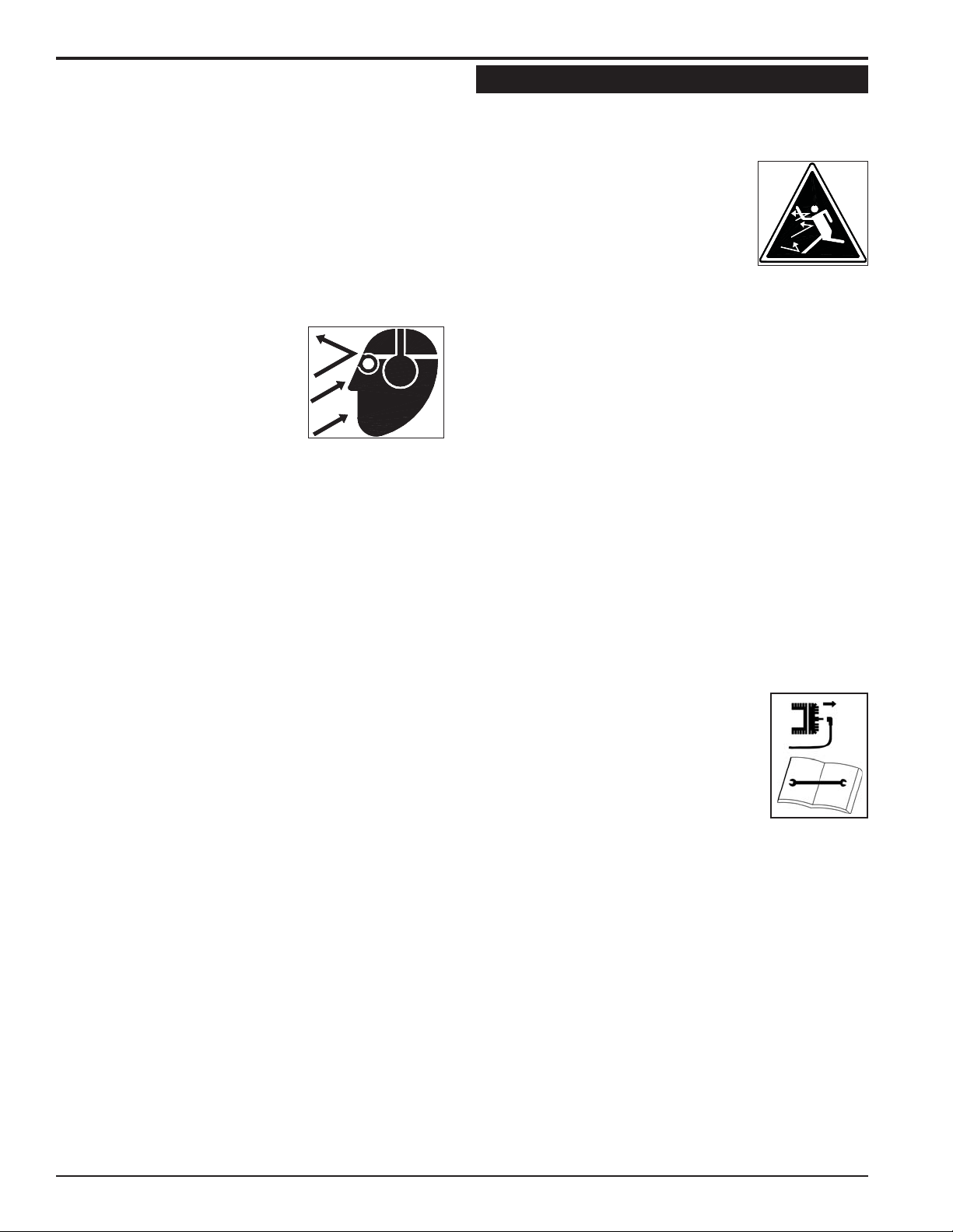
Obtain and wear safety glasses and use hearing 4.
protection at all times when operating this machine.
Avoid wearing loose fitted clothing. Never operate this 5.
12 INCH CHIPPER
1
Page 6
SAFETY
machine while wearing clothing with drawstrings that
could wrap around or get caught in the machine.
Do not operate this machine if you are under the 6.
influence of alcohol, medications, or substances that
can affect your vision, balance or judgement. Do not
operate if tired or ill. You must be in good health to
operate this machine safely.
Do not operate this equipment in the vicinity of 7.
bystanders. Keep the area of operation clear of all
persons, particularly small children. It is recommended
that bystanders keep at least 50
feet (15 meters) away from the
area of operation.
Do not allow children to operate 8.
this equipment.
Use only in daylight or good artificial light.9.
Do not run this equipment in an enclosed area. Engine 10.
exhaust contains carbon monoxide gas, a deadly
poison that is odorless, colorless and tasteless. Do not
operate this equipment in or near buildings, windows
or air conditioners.
Always use an approved fuel container. Do not remove 11.
gas cap or add fuel when engine is running. Add fuel
to a cool engine only.
Do not fill fuel tank indoors. Keep open flames, sparks, 12.
smoking materials and other sources of combustion
away from fuel.
Do not operate machine without shields in place. 13.
Failure to do so may cause serious injury or death.
Keep all guards, deflectors, and shields in good 14.
working condition.
Before inspecting or servicing any part of this machine, 15.
shut off the machine and make sure all moving parts
have come to a complete stop. Disconnect the battery
and remove the ignition key where applicable.
Check that all screws, nuts, bolts, and other fasteners 16.
are secured, tightened and in proper working condition
before starting the machine.
Do not transport or move machine while it is operating 17.
or running.
1.4 OPERATION SAFETY
Always stand clear of discharge area when operating 1.
this machine. Keep face and body away from feed
and discharge openings.
Keep hands and feet out of feed and 2.
discharge openings while machine is
operating to avoid serious personal
injury. Stop and allow machine to
come to a complete stop before
clearing obstructions.
Set up your work site so you are not endangering traffic 3.
and the public. Take great care to provide adequate
warnings.
Do not climb on machine when operating. Keep proper 4.
balance and footing at all times.
Check cutting chamber to verify it is empty before 5.
starting the machine.
The disk will continue to rotate after being disengaged. 6.
Shut off the machine and make sure all moving parts
have come to a complete stop before inspecting or
servicing any part of the machine. Disconnect the
battery and remove the ignition key if applicable.
Do not insert branches with a diameter larger than 7.
the max chipper capacity into machine or machine
damage may occur.
When feeding material into machine, do not allow 8.
metal, rocks, bottles, cans or any other foreign material
to be fed into the machine.
Ensure debris does not blow into traffic, parked cars, 9.
or pedestrians.
Keep the machine clear of debris and 10.
other accumulations.
Do not allow processed material to 11.
build up in the discharge area. This
may prevent proper discharge and
can result in kickback of material
through the feed opening.
If the machine becomes clogged, the cutting mechanism 12.
strikes any foreign object, or the machine starts
vibrating or making an unusual noise, shut off machine
immediately and make sure all moving parts have
come to a complete stop. Disconnect the battery and
remove the ignition key if applicable. After the machine
stops: A) Inspect for damage, B) Replace or repair
any damaged parts, and C) Check for and tighten any
loose parts.
On electric start models, disconnect cables from battery 13.
before doing any inspection or service. Remove key .
Check blade bolts for proper torque after every 8 hours 14.
of operation. Check blades and rotate or resharpen
daily or as required to keep blades sharp. Failure to do
so may cause poor performance, damage or personal
injury and will void the machine warranty.
2
12 INCH CHIPPER
Page 7

SAFETY
1.5 FEED ROLLER SAFETY
The feed roller can cause serious injury or death. Keep 1.
hands, feet and clothing away from the feed roller and
chipper disk blades.
Never climb onto the feed chute when the unit is 2.
operating or running.
Do not overreach. Keep proper balance and footing 3.
at all times.
Never allow anyone to sit on the feed chute.4.
When feeding material into the feed roller wear eye, 5.
face and hearing protection.
Stand to side of feed chute when feeding material and 6.
release material quickly.
When inspecting or servicing the feed roller, secure 7.
the feed roller in the raised position using the lock pin,
if applicable.
1.6 MAINTENANCE & STORAGE SAFETY
Before inspecting, servicing, storing, or changing 1.
an accessory, shut off the machine and make sure
all moving parts have come to a complete stop.
Disconnect the battery and remove the ignition key
where applicable.
Replace any missing or unreadable safety decals. 2.
Refer to the safety decal section for part numbers.
Allow machine to cool before storing in an 3.
enclosure.
Store the machine out of reach of children and where 4.
fuel vapors will not reach an open flame or spark.
Never store this machine with fuel in the fuel tank 5.
inside a building where fumes may be ignited by an
open flame or spark. Ignition sources can be hot water
and space heaters, furnaces, clothes dryers, stoves,
electric motors, etc.
Drain the fuel and dispose of it in a safe manner for 6.
storage periods of three months or more.
1.7 TOWING SAFETY
Position and lock discharge tube 1. over the hitch prior
to transporting the machine.
Insert transport safety pin and clip, and set brake 2.
handle to locked position, if applicable.
Connect hitch safety chains. Tighten trailer hitch bolts. 3.
Do not attempt to tow the trailer if the vehicle is not
equipped with a 2” (50 mm) ball.
Do not exceed the maximum towing speed indicated 4.
on tire sidewall. Inflate tires to manufacturer’s
specifications as stated on the tire sidewall.
Optimum towing performance can be achieved by 5.
maintaining a horizontal trailer hitch.
Check wheel lug bolts periodically to ensure they are 6.
tight and secure.
Make sure the jack stand and the rear stabilizer (where 7.
applicable) on the trailer are in the UP position during
towing. Place the jack stand on a level surface and
secure it in the DOWN position before using.
Never allow passengers to ride on the machine.8.
If applicable, shut off fuel supply when towing.9.
Towing laws may vary in different countries/regions/10.
states. It is recommended that you contact your local
motor vehicle department for any special regulations
that pertain to towing and know the laws of any country/
region/state you travel through.
1.8 BATTERY SAFETY
Improper use and care of the battery on electric
start models can result in serious personal injury or
property damage. Always observe the following safety
precautions.
Poison/Danger - Causes Severe Burns. The battery
contains sulfuric acid. Avoid contact with skin, eyes or
clothing. Keep out of reach of children.
ANTIDOTE-External Contact: Flush immediately •
with water.
ANTIDOTE-Internal: Drink a large amount of •
water or milk. Follow with milk of magnesia,
beaten egg or vegetable oil. Call a physician immediately.
ANTIDOTE-Eye Contact: Flush with water for 15 •
minutes. Get prompt medical attention.
The battery produces explosive gases. Keep sparks, 1.
flame or cigarettes away . Ventilate area when charging
battery. Always wear safety goggles when working
near battery.
The battery contains toxic materials. Do not damage 2.
battery case. If case is broken or damaged, avoid
contact with battery contents.
Neutralize acid spills with a baking soda and water 3.
solution. Properly dispose of a damaged or wornout battery. Check with local authorities for proper
disposal methods.
Do not short circuit battery. Severe fumes and fire 4.
can result.
Before working with electrical wires or components, 5.
disconnect battery ground (negative) cable first.
Disconnect positive cable second. Reverse this order
when reconnecting battery cables.
DANGER / POISON
FLUSH EYES
IMMEDIATELY
SHIELD EYES
EXPLOSIVE GASES
CAN CAUSE
BLINDNESS OR
INJURY
KEEP OUT OF THE REACH OF CHILDREN. DO NOT TIP. KEEP VENT CAPS TIGHT AND LEVEL.
NO
• SPARKS
• FLAMES
• SMOKING
SULFURIC
ACID
CAN CAUSE
BLINDNESS OR
SEVERE BURNS
WITH WATER
GET
MEDICAL
HELP
FAST
ENGLISH
12 INCH CHIPPER
3
Page 8
SAFETY
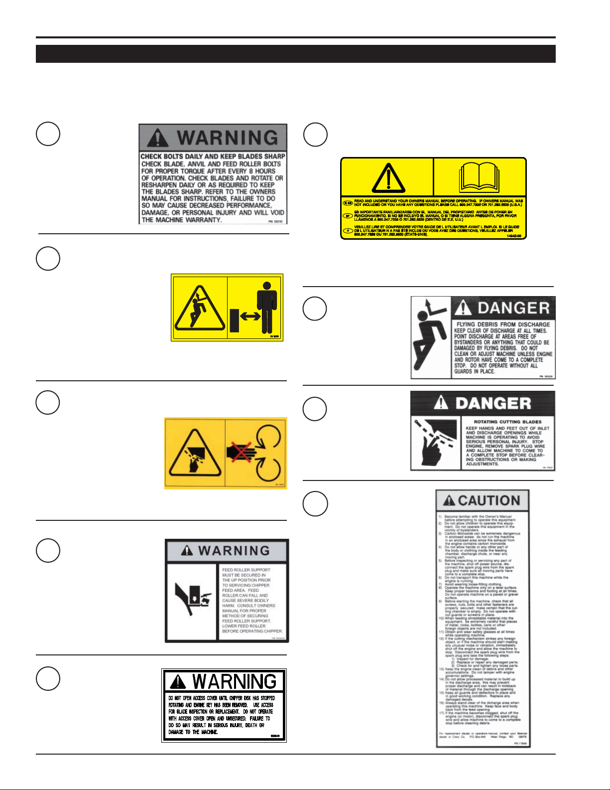
1.9 SAFETY DECALS
See Section 1.10 for decal locations. Familiarize yourself with all of the safety and operating decals on the machine
and the associated hazards. See the engine owner’s manual or contact the engine manufacturer for engine safety
instructions and decals. Make certain that all safety and operational decals on this machine are kept clean and in good
condition. Decals that need replacement must be applied to their original locations.
PN 12010
1
6
PN 14942-00
PN 12173
2
DO NOT OPERATE THIS
EQUIPMENT IN THE VICINITY
OF BYSTANDERS. DO
NOT ALLOW CHILDREN TO
OPERATE THIS EQUIPMENT.
ALWAYS STAND CLEAR OF
DISCHARGE AREA WHEN
OPERA TING THIS MACHINE. KEEP F ACE AND BODY AW AY
FROM DISCHARGE AREAS.
PN 12175
3
KEEP HANDS AND FEET OUT
OF INLET AND DISCHARGE
OPENINGS WHILE MACHINE
IS OPERATING TO AVOID
SERIOUS PERSONAL
INJURY. STOP AND ALLOW
MACHINE TO COME TO A
COMPLETE STOP BEFORE CLEARING OBSTRUCTIONS.
READ AND UNDERSTAND THIS OWNER/OPERATORS MANUAL.
BE COMPLETELY FAMILIAR WITH THE CONTROLS AND THE
PROPER USE OF THIS EQUIPMENT.
7
PN 16558
PN 17837
8
PN 17846
9
4
PN 14049-00
5
PN 14369-00
4
12 INCH CHIPPER
Page 9
SAFETY
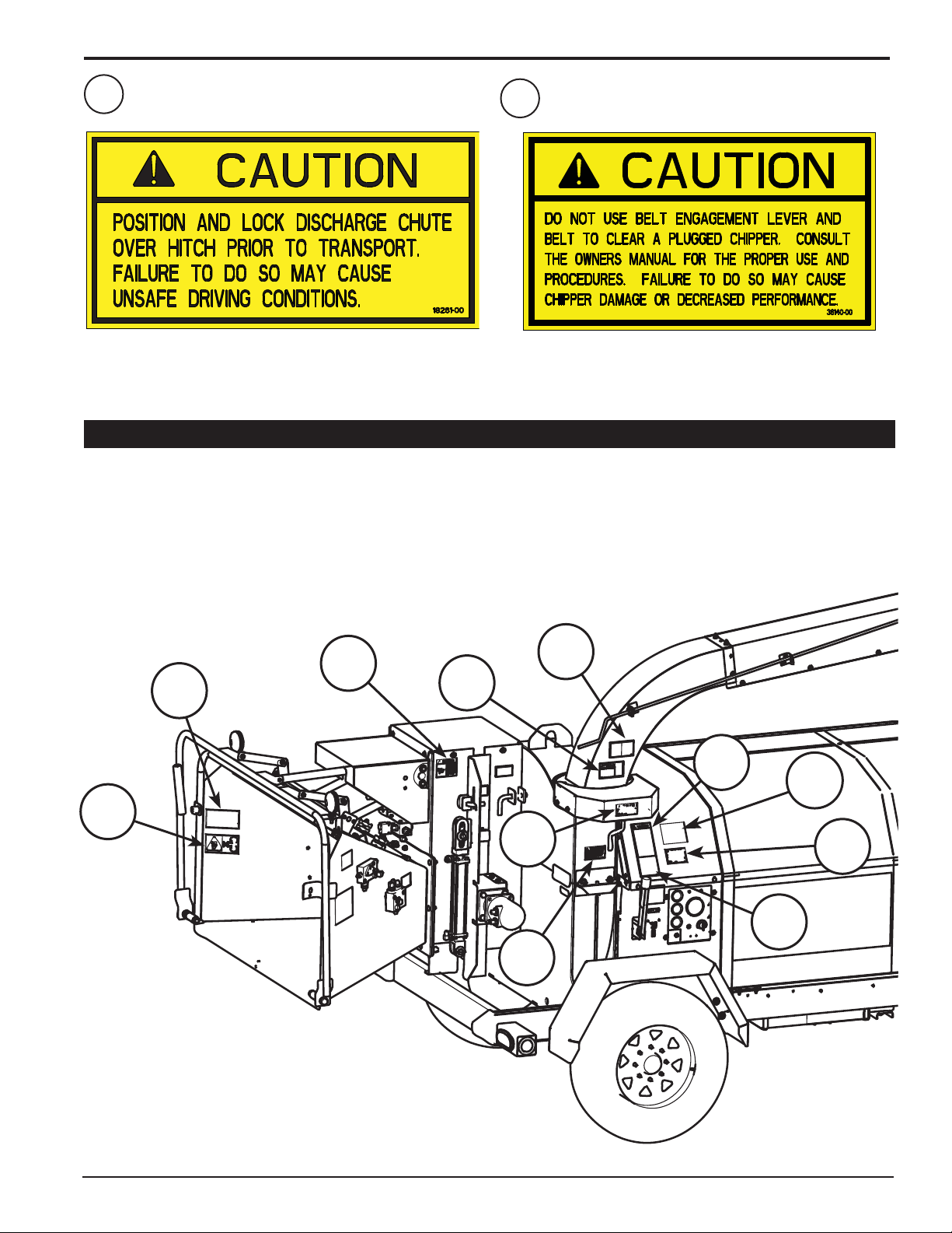
10
The numbers below correspond to the decals in Section 1.9. Familiarize yourself with all of the safety and operational
decals on the machine and the associated hazards. See the engine owner’s manual or contact the engine manufacturer
for engine safety instructions and decals. Make certain that all safety and operating decals on this machine are kept
clean and in good condition. Decals that need replacement must be applied to their original locations.
PN 18261-00
1.10 SAFETY DECAL LOCATIONS
11
PN 36140-00
ENGLISH
3
8
4
2
10
5
7
9
1
6
11
12 INCH CHIPPER
5
Page 10

2
Section
ASSEMBLY
2.1 INSTALL A BATTERY
You will need to purchase a battery. Choose a battery that
meets or exceeds the following specifi cations:
Nominal Voltage: 12 Volt
CCA: 925 with 1050 reserve capacity
Type: Exide Group 31
HP 31E (SAE Post Term)
To install the battery:
Locate the battery box (shown below).1.
Remove the cover of the battery box and set the battery 2.
inside.
Hook up the battery by connecting the red wire to the 3.
positive terminal and the black wire to the negative
terminal.
Reattach battery box cover.4.
Tools can also be stored in the extra space of the battery
box. The tools should be secured in their own container.
2.2 ADD MOTOR OIL
Check the oil level and, if needed, fi ll the engine crankcase
with the type and amount of oil specifi ed in the engine
owner’s manual.
There are two oil filler caps (see below). Either can be used
to add oil.
BATTERY
BOX
Oil Filler Cap
Other oil filler cap and dipstick
6
12 INCH CHIPPER
Page 11

ASSEMBLY
2.3 FILL THE FUEL TANK
WARNING
Gasoline and diesel fuels are highly
fl ammable and their vapors are explosive.
To prevent personal injury or property
damage:
Store fuel only in approved containers, in
well ventilated, unoccupied buildings, away
from sparks or fl ames. A container with a capacity of 2
gallons or less with a pouring spout is recommended.
Do not fi ll the fuel tank while the engine is hot or running,
since spilled fuel could ignite if it comes in contact with
hot parts or sparks from ignition. Do not start the engine
near spilled fuel. Never use fuel as a cleaning agent.
DO NOT MIX OIL WITH FUEL.
Use only those types of fuels that are recommended in
your engine owner’s manual.
To add fuel:
Stop engine, wait for all parts to stop moving and 1.
disconnect spark plug wire. Remove key from key
switch. Allow the engine and muf fler to cool for at least
three minutes.
Clean area around fuel fill cap and remove cap.2.
Using a clean funnel, fill fuel tank to 1/2” below bottom 3.
of filler neck to provide space for any fuel expansion.
Install fuel fill cap securely and wipe up any spilled
gasoline.
2.4 ADD COOLANT
Check the level of coolant before you start the diesel
engine. While operating, make sure the fl uid is between
the full and the low marks. Add if necessary. Refer to the
engine owner’s manual for further coolant information.
ENGLISH
Coolant tank
2.5 ADD HYDRAULIC FLUID
Hydraulic fl uid drives the feed roller. The machine was
shipped with fl uid, as it was tested at the factory. However ,
check the fl uid levels before initial operation and add if
necessary.
The hydraulic pump requires premium hydraulic fl uids
containing high quality rust, oxidation, and foam inhibitors.
These include premium turbine oils, API CD engine oils
per SAE J183, M2C33F or G automatic transmission
fl uids meeting Allison C-3 or Caterpillar TO-2, and certain
specialty agricultural tractor fl uids.
Fuel tank and cap
IMPORTANT
Do not attempt to start the engine at this time. Wait
until you have read the complete starting instructions
in the Operation Section of this manual.
12 INCH CHIPPER
The hydraulic fluid level should be checked before each use
7
Page 12

3
FEATURES & CONTROLS
Section
Understanding how your machine works will help you achieve the best results when using your machine. The following
descriptions defi ne the features and controls of your machine.
DISCHARGE
CAP
FEED ROLLER
LOCK UP PIN
KNIFE
ACCESS
COVER
KNIFE ACCESS
COVER LOCK
PIN
DISCHARGE
CHUTE
FEED ROLLER
CONTROL BAR
HITCH
ENGAGEMENT
HANDLE
FEED ROLLER
SPEED CONTROL
FEED ROLLER
LIFT CONTROL
8
Feed Roller Controls
Control Panel
12 INCH CHIPPER
Page 13

FEATURES & CONTROLS
CHARGE LAMP
The charge lamp lights up to warn the operator that
the battery charge is low. If this should happen during
operation, immediately stop the engine and refer to the
engine owner's manual for service and maintenance
information.
DISCHARGE CAP
Directs the discharge of material vertically . The discharge
cap can be raised and lowered vertically by turning the
discharge cap crank until the desired location is reached.
DISCHARGE CHUTE
Directs the discharge of chipped material horizontally . The
discharge chute can be rotated 360° horizontally by turning
the discharge chute rotator. Turn the discharge chute
towards the roadside for greater ease when opening the
rotor cover. Position the discharge chute out of the way
to open the hood. The hood does not clear the discharge
chute unless the chute is turned to the side.
ENGAGEMENT HANDLE
During engine start-up, the engagement handle must be in
the disengaged position. When the engine is at 1 100 RPM,
carefully engage the rotor by slowly pushing the engagement
handle up, and allow the rotor to speed up gradually.
Engaging the chipper too quickly with the engine at full or
half throttle will bog down the engine and will shorten the
life of the belt. To disengage the rotor, first idle the engine
down and then pull the engagement handle down.
FEED ROLLER CONTROL BAR
Move the control bar to engage the feed roller. The cycle
of the control bar, forward to back, is REVERSE (R),
FORWARD (F), STOP, REVERSE (R).
FEED ROLLER LIFT CONTROL
Used to lift the feed roller. The belt does not have to be
engaged to lift the feed roller. The feed roller can be raised
during operation for better feeding of larger branches into
the chipper and for clearing a plugged rotor.
FEED ROLLER LOCK UP PIN
Use the lock up pin to secure the feed roller in the raised
position.
FEED ROLLER SPEED CONTROL
By controlling the speed of the feed roller, the operator has
better control over the rate at which material is fed into the
chipper (see Sec. 4.7).
FUEL GAUGE
Shows fuel level.
GLOW LAMP
The glow lamp will go out when the pre-heating is
completed. See the engine owners manual for additional
pre-heating instructions.
KEY SWITCH
The control panel houses the key switch. Turn the key to
the left to preheat the glow plug. Then turn the key to the
right to start the machine.
KNIFE ACCESS COVER
To raise the knife access cover, see Sec. 4.6.
KNIFE ACCESS COVER LOCK PIN
Used to secure the knife access cover in a raised position. To
raise the cover, use the jack located under the engine hood.
OIL PRESSURE GAUGE
The oil pressure lamp lights up to warn the operator that
the engine oil pressure has dropped below the prescribed
level. If this should happen during operation, immediately
stop the engine and refer to the engine owners manual for
service and maintenance information.
RESET BUTTON
In the event of a power surge, the reset button will pop out.
Before restarting the engine, push the button.
TEMPERATURE GAUGE
Monitors the engine temperature. See the engine owners
manual for additional engine temperature information.
THROTTLE
This controls the speed of the engine. Increase the throttle
by pushing up on the toggle switch momentarily and
releasing it. Repeat until the machine is at full throttle. To
decrease the throttle, push down on the toggle switch and
hold until the engine is idling at low throttle.
ENGLISH
12 INCH CHIPPER
9
Page 14

4
Section
OPERATION
As with any other piece of outdoor equipment, getting the
feel for how your machine operates and getting to know
the best techniques for particular jobs are important to
overall good performance.
CHIPPING OPERATION
The chipping operation takes place on the front of the
machine, where hardened steel chipper blades are
mounted on a rotating disk assembly . Material fed into the
chipper chute is sliced into small chips and propelled out
through a discharge tube.
WARNING
Before operating your machine, be sure you read and
understand all safety , controls and operating instructions
in this Owner/Operators manual and on your machine.
Failure to follow these instructions can result in serious
injury or property damage.
WARNING
Move machine to a clear, level area outdoors before
starting. Do not operate in the vicinity of bystanders.
Make sure cutting chamber is empty before starting.
4.1 STARTING THE CHIPPER
Move the machine to a clear, level area outdoors before
starting. Do not operate in the vicinity of bystanders.
Make sure the cutting chamber is empty before starting.
4.2 STOPPING THE CHIPPER
Lower the engine speed to 1500 RPM by pushing 1.
down on the throttle toggle switch located on the
control panel.
Disengage the engagement handle to release belt.2.
Let machine idle for a few seconds.3.
Turn the key switch to the OFF position.4.
Allow machine to come to a complete stop. 5.
4.3 DIRECTING THE DISCHARGE CHUTE
The discharge chute can rotate 360° and lock into different
positions using the chute rotator. To adjust the discharge
chute, pull the rotator lock down. Turn the discharge chute
until the chute faces the desired position; then let go of the
rotator lock and fine tune the position of the chute until the
lock snaps back into place.
The discharge cap directs how high and how far the chipped
material blows. Adjust the discharge cap by turning the
discharge cap crank. Turn the handle clockwise to raise the
discharge angle. Turn the handle counterclockwise to lower
the discharge angle.
Check engine oil level before starting.1.
Fill the fuel tank with fresh, clean diesel fuel. See the 2.
engine owners manual for instructions on bleeding the
fuel system on initial start up or if fuel runs out.
Make sure the engagement handle is disengaged.3.
Move the key switch to the PREHEAT position. Wait 4.
until the glow lamp lights up to indicate that the glow
plug has completed pre-heating.
Turn the key switch to the right to start the engine. Re-5.
lease the key switch immediately when the engine starts.
Do not crank engine for more than 10 seconds.
When the engine reaches 1 100 RPM, engage the rotor 6.
by SLOWLY pushing the engagement handle up.
Allow the machine to reach full RPM (2600 RPM) 7.
before starting to chip material.
10
DISCHARGE
CAP CRANK
DISCHARGE
CHUTE
ROTATOR
ROTATOR LOCK
Directing the discharge chute
12 INCH CHIPPER
Page 15

OPERATION
4.4 OPERATING THE CHIPPER
WARNING
Read and follow all safety instructions in this manual.
Failure to operate the machine in accordance with
the safety instructions MAY RESULT IN PERSONAL
INJURY!
CAUTION
Obtain and wear safety glasses at all times when operating
the machine.
Do not wear loose fitting clothing.
The operator should always wear heavy boots, gloves,
pants and a long-sleeved shirt.
Use common sense and practice safety to protect
yourself from branches, sharp objects, and other
harmful objects.
WARNING
Never lean over the chipper chute to push objects
into the cutting device. Use a push stick or brush
paddle.
Never use shovels or forks to feed brush. They can
cause extensive damage if they contact the blades.
In addition, metal pieces can be ejected from the
chipper chute and cause serious injury or death.
Never feed brush into the chute with your feet.
Never use hands or feet to clear materials that build up
in the chute.
The machine chips a variety of materials into a more
readily decomposed or handled condition. The following
guidelines will help you get started.
Run unit at full operating speed1. (2600 RPM) before
starting to chip material.
Limbs fed in to the chipper chute must be 12 inches 2.
(30 cm) in diameter or less. Trim side branches that
cannot be bent enough to feed into the chipper chute.
Hold small diameter branches together in a bundle and
feed in simultaneously.
Exclude pieces of metal, rocks, bottles, cans, and 3.
other foreign objects when feeding material into the
machine.
Feed brush from the side of the chipper chute,4. rather
than from the front. Step aside to avoid being hit by the
brush moving into the chipper.
Place limb, butt end first, into the chipper chute 5. until
it contacts the chipper blades. The actual feed rate
of the limb into the chipper will depend on the type of
material fed and sharpness of the cutting blades.
Adjust the speed of the feed roller, 6. if necessary , with
the feed roller speed control (see Sec. 4.7).
To prevent excessive banging and slamming 7. on
the top of the chipping chamber that may occur when
feeding larger logs (8" and above), lift the feed roller
with the feed roller lift control (see Sec 4.6).
If the engine slows to where it may stall,8. stop feeding
material and allow the engine to recover. Feed material
more evenly.
If the chipper jams,9. remove the branch and rotate it
before reinserting it into the chute. Alternately insert
and retract the limb or insert continuously at a rate that
will not kill the engine.
Do not use the clutch to clear a plugged rotor. 10. This
may cause belt damage. Refer to the instructions for
clearing a plugged rotor in the Service and Maintenance
section.
Alternate greener material with dry material 11. to
lubricate the chipping blades for longer life and better
performance. Chipping dead, dry material will create
heat and dull the chipping blades quickly.
Sharpen the chipping blades periodically. 12. Check
the sharpness of the blades every 5-15 hours. Refer
to the Service and Maintenance section for sharpening
instructions.
4.5 FEED ROLLER CONTROL BAR
Feed Roller Control Bar is used to manually control the
direction of the feed roller rotation.
Move the feed roller bar to FORWARD (F) when you want
the materials to feed into the chipper.
Move the feed roller bar to REVERSE (R) when you want
the chipper push materials back out of the feed chute
(when materials become jammed).
Move the feed roller bar to STOP to halt the rotation of the
feed roller.
FEED ROLLER
CONTROL BAR
ENGLISH
12 INCH CHIPPER
11
Page 16

OPERATION
4.6 RAISING THE FEED ROLLER
The feed roller lift control is used to raise the feed roller
during operation so that larger logs (over 8 inches) can be
fed into the chipper easier. It is also used to gain access to
the feed roller when servicing the machine. The belt does
not have to be engaged to use the feed roller lift, but the
machine must be running. To raise the feed roller:
Push the feed roller control to the right and hold it until 1.
the feed roller is fully raised.
Secure using the lock up pin located on the roller slide 2.
when servicing the machine. Do not use the lock up pin
when raising the feed roller to accomodate large logs.
Release the feed roller control.3.
T o lower the feed roller , remove the lockup pin (this may 4.
require raising the feed roller slightly), then release the
feed roller control.
NOTE
Using the feed roller lift makes feeding larger logs
(8" and above) easier and prevents the banging and
slamming to the top that can occur.
4.7 FEED ROLLER SPEED CONTROL
The feed roller speed control is used to control the rate at
which material is pulled into the chipper.
When beginning operation, the control should be set in mid
range. Adjust the speed by slightly unscrewing the black
knob and then turning the control. To increase the speed
of the feed roller, move the lever clockwise. To slow the
speed, move the lever counterclockwise. After adjusting,
retighten the knob.
It is recommended that the feed roller operate at a faster
rate for smaller branches and at a slower rate for larger
branches.
Feed Roller
Lock Up Pin
Lever
Knob
4.8 RAISE THE KNIFE ACCESS COVER
Rotate the discharge chute toward the roadside.1.
Remove the two 1/2" x 1-1/4" bolts, nuts and washers 2.
securing the cover to the chipper housing (see below).
Feed Roller Lift Control
Knife Access
Cover Lock
Pin
12
Feed Roller Lock Up Pin
12 INCH CHIPPER
Page 17

Lift the engine hood and locate the knife access cover 3.
jack inside the chipper housing next to the hydraulic
fluid reservoir (see below).
Turn the wing nut located on the bottom of the jack to 4.
the right and pump the handle.
4.9 FEED CONTROLLER
OPERATION
The chipper is equipped
with a pre-programmed
feed controller located
next to the engagement
handle. The controller
monitors chipper rotor
RPM, controls the feed
roller, and provides
routine maintenance
alerts.
The controller functions
are further detailed
below:
The controller 1.
monitors the RPM of the
chipper rotor. If the RPM
drops below the preset
range, the feed roller
is stopped. When the
RPM reach an acceptable level, the feed roller
is reengaged.
ENGLISH
Secure the cover using the lock pin located on the 5.
outside of the chipper housing (see below).
To lower the cover, remove the lock pin and turn the 6.
wing nut located on the jack to the left to release the
hydraulic pressure.
The controller 2.
also has a “try again”
feature. If the hydraulic pressure of the feed roller is
too high (if the feed roller becomes obstructed) the
controller will reverse the feed roller, removing the
unchipped material. The controller will then reengage
the roller forward and try to feed the material again. If
this cycle continues, remove the obstruction manually .
Trim or reposition material if necessary.
Lights on the controller give the following information:3.
Error light will flash 10 times every 100 hours •
of operation upon startup to indicate the engine
oil should be changed.
Error light will flash 5 times every 15 hours of •
operation upon startup to indicate the chipper
blades should be sharpened.
Secure the knife access cover to the chipper housing 7.
using two 1/2" x 1-14" bolts, nuts and washers.
NOTE
When closing the rotor cover, make sure the bolts are
securely tightened. If they are not, the safety switch
may respond as though the battery is dead.
12 INCH CHIPPER
Steady power light indicates controller operat-•
ing normally , blinking power light indicates low
or no power to the controller.
To reset service alerts, locate the light green wire in 4.
the engine compartment next to the hour meter. Connect the green wire to the red wire connector for five
seconds.
13
Page 18

5
SERVICE & MAINTENANCE
Section
5.1 SERVICE AND MAINTENANCE SCHEDULE
The items listed in this service and maintenance schedule are to be checked, and if necessary , corrective action taken.
This schedule is designed for units operating under normal conditions. If the unit is operating in adverse or severe
conditions, it may be necessary for the items to be checked and serviced more frequently.
SEE ENGINE OWNER’S MANUAL FOR FURTHER ENGINE MAINTENANCE AND TROUBLESHOOTING
INFORMATION.
SERVICE AND MAINTENANCE SCHEDULE
FREQUENCY
COMPONENT
AIR CLEANER CHECK AND CLEAN (1)
AIR INTAKE CLEAN (1)
ENGINE OIL CHANGE (1)
FUEL FILTER REPLACE
SPARK PLUG
HYDRAULIC OIL CHECK/FILL
ENGINE OIL CHECK/FILL
FUEL TANK CHECK/FILL
ALL INTERNAL AND
EXTERNAL NUTS AND
BOLTS
TIRE PRESSURE CHECK
BATTERY CONNECTIONS CHECK
CHIPPER ANVIL
MAINTENANCE
REQUIRED
CHECK CONDITION AND
GAP
CHECK TIGHTNESS
CHECK CLEARANCE AND RETORQUE TO 75 FT -LBS. (2)
REFER TO
ENGINE
OPERATOR’S
MANUAL
BEFORE
EACH
USE
EVERY
8
HOURS
EVERY
25
HOURS
EVERY
50
HOURS
EVERY
200
HOURS
EVERY
YEAR
CHIPPER BLADES
ENTIRE MACHINE CLEAN
DRIVE BELT CHECK
HYDRAULIC DRIVE BELT CHECK
BELT TENSION CHECK
BELT/PULLEY ALIGNMENT CHECK
GREASE ZERKS LUBE
HYDRAULIC OIL FILTER REPLACE
WHEEL BEARINGS CHECK AND REPACK
COOLING SHROUDS CLEAN
STARTER DRIVE SERVICE
(1) PERFORM MORE FREQUENTLY UNDER EXTREMELY DUSTY CONDITIONS.
(2) PERFORM MORE FREQUENTLY WHEN CHIPPING DRY OR DIRTY WOOD.
As the Limited Warranty states, failure by the Owner to perform normal maintenance will void the machine’s warranty. The aggressive,
high-speed nature of chipping REQUIRES THE OWNER TO PERFORM THE ABOVE LISTED NORMAL MAINTENANCE. Special
consideration to maintain and re-torque the CHIPPER ANVIL, CHIPPER BLADES, AND ALL INTERNAL AND EXTERNAL NUTS AND
BOLTS is the sole responsibility of the Owner. Failure by the Owner to do so shall be cause for denial of warranty.
14
CHECK SHARPNESS AND RETORQUE TO 230 FT -LBS. (2)
12 INCH CHIPPER
Page 19

SERVICE & MAINTENANCE
WARNING
BEFORE INSPECTING OR SERVICING ANY PART OF THIS MACHINE, SHUT OFF POWER SOURCE, REMOVE KEY,
DISCONNECT THE BATTERY CABLES AND MAKE SURE ALL MOVING PARTS HAVE COME TO A COMPLETE STOP.
5.2 CHIPPER BLADE MAINTENANCE
The chipper blades will eventually become dull, making
chipping diffi cult and adding extra strain on the machine.
CHECK THE SHARPNESS OF THE BLADES EVERY
5 - 15 HOURS OF OPERATION AND SHARPEN AS
NEEDED.
Your blades need to be sharpened if:
• Machine vibrates severely when material is fed into the
chipper.
• Small diameter branches do not self-feed.
• Chips discharge unevenly or have stringy tails, especially when chipping green branches.
Before you sharpen the chipping blades, check for
permanent damage. Replace the blade if:
• There are cracks, broken corners or nicks greater than
1/8" (see below).
CRACK
GREATER
THAN 1/8”
BROKEN
CORNER
NICK GREATER
THAN 1/8”
5.3 REMOVING THE BLADES
Raise the knife access cover using the jack (Section 1.
4.8) and secure with the lock pin.
Rotate the disk until a chipper blade is accessible.2.
Secure the disk to prevent movement while removing 3.
the chipping blades.
Remove the three 5/8" x 3" bolts and nuts holding the 4.
chipper blade to the disk and remove the blade; repeat
for remaining blades.
Inspect blades to see if cracks or nicks are visible. If 5.
cracks are present, replace the blades. If nicks can not
be removed by sharpening blade, replace the blade.
5.4 SHARPENING THE BLADES
The blades can be ground on a bench grinder or by a
professional.
Never sharpen or grind the mounting surfaces of the 1.
blades. This will cause the edge to roll and the blade will
be damaged, resulting in poor chipping performance.
Regrind the angled edge of the chipping blades to 45 2.
degrees. Make sure some type of fixture is used to
correctly hold the blade at the proper angle.
Be careful when grinding so that the blade does not 3.
become overheated and change color. This will remove
the heat-treated properties.
Use short grinding times and cool with water or some 4.
type of liquid coolant.
ENGLISH
• The base of the cutting edge is worn or has been re-
sharpened so that it no longer extends past the chipping
slot (see below).
CHIPPER
DISC
CHIPPING
SLOT
NEW
BLADE
CHIPPER
DISC
CHIPPING
SLOT
BLADE IS
TOO SHORT,
MUST BE
REPLACED
WARNING
Chipping blades are sharp! Use caution when working
on machine to avoid injury.
12 INCH CHIPPER
Remove an equal amount off each blade to maintain 5.
rotor balance.
Small imperfections such as nicks and burrs on the 6.
flat side of the blade will not affect the chipping performance of the machine.
For blades that have been repeatedly sharpened, 7.
ensure that the sharpened surface extends past the
chipping slot opening. If it does not extend past the
opening, the blades should be replaced.
MOUNTING SURFACE
(DO NOT GRIND)
MOUNTING SURFACE
(DO NOT GRIND)
SHARPENED
SURFACE
45°
SHARPENED
SURFACE
.63
Both ends of the blade can be sharpened
15
Page 20

SERVICE & MAINTENANCE
WARNING
BEFORE INSPECTING OR SERVICING ANY PART OF THIS MACHINE, SHUT OFF POWER SOURCE, REMOVE KEY,
DISCONNECT THE BATTERY CABLES AND MAKE SURE ALL MOVING PARTS HAVE COME TO A COMPLETE STOP.
5.5 INSTALLING THE BLADES
Secure the disk to prevent movement during installation.1.
Place a blade on the disk and attach with three 5/8" 2.
x 3" bolts and nuts. Torque to 230 ft-lbs. Repeat for
remaining blades.
Lower the knife access cover.3.
Secure the knife access cover to the chipper housing 4.
using two 1/2" x 1-1/4" bolts, nuts and washers.
5.6 SETTING BLADE CLEARANCE
Check the clearance every 8 hours of operation and adjust
if needed. The chipping anvil is reversible. All four sides
of the anvil can be used for chipping. Use the following
guide when setting the blade clearance:
If you are chipping materials that are primarily • smaller
than 6 inches, use an anvil gap of 1/4” to 3/8”.
If the materials are• 6 inches and larger, use an
anvil gap of 3/8” to 7/16”.
To adjust the anvil:
With the chipper motor running and the engagement 1.
handle DISENGAGED, raise and secure the feed
roller (Section 4.6).
Adjustment
Nuts
View of anvil bolts and adjustment nuts from underneath machine
Measure the clearance between the chipping blade 8.
and the anvil from inside the feed chute. Adjust both
nuts equally until the clearance between the chipping
blades and the anvil is correct.
Anvil
Bolts
DANGER
Ensure that the feed roller is raised and secure before
entering the feed chute. Failure to do so can result in
serious injury or death.
Shut the engine off, remove the key , and allow the rotor 2.
to come to a complete stop.
Lift the knife access cover and secure with the lockup 3.
pin (Sec. 4.8).
Rotate the disk until a chipping blade is even with the 4.
anvil.
Secure the chipper disk to prevent movement during 5.
adjustment (for example, by wedging a piece of wood
between a rotor paddle and the housing).
Loosen the three 1/2" x 1-1/2" bolts that secure the 6.
anvil to the chipper housing (access is from underneath
machine, see picture).
Loosen the two 3/8" adjustment nuts located inside the 7.
anvil backplate (access is from underneath machine,
see picture).
NOTE
If the anvil edge is damaged or worn unevenly, remove
anvil and use one of the other three edges. If all edges
are damaged or worn unevenly, replace the anvil.
16
12 INCH CHIPPER
Blade
Anvil
Measure
Here
Measuring clearance between blade and anvil
Rotate the disk to ensure there is proper clearance be-9.
tween ALL four chipping blades and the anvil. The anvil
gap may be different for each blade. Ensure the gap is
set for the closest blade. Adjust anvil if necessary.
Once proper clearance is achieved, tighten the three 10.
1/2" x 1-1/2" bolts to secure the anvil to the frame.
Tighten the two 3/8" adjustment nuts located inside the 11.
anvil backplate.
Lower the knife access cover by removing the lock pin, 12.
and turning the wing nut on the jack to the left.
Remove the feed roller lock up pin, lower the feed roller 13.
and resume operation.
Page 21

WARNING
BEFORE INSPECTING OR SERVICING ANY PART OF THIS MACHINE, SHUT OFF POWER SOURCE, REMOVE KEY,
DISCONNECT THE BATTERY CABLES AND MAKE SURE ALL MOVING PARTS HAVE COME TO A COMPLETE STOP.
5.7 REPLACING THE DRIVE BELT
Check the condition of the drive belt annually or after every
25 hours of operating, whichever comes first. If the belt is
cracked, frayed, or worn, replace it. To replace or adjust
drive belt, proceed as follows:
Release engagement handle to loosen the belts.1.
Remove the four 3/8" x 1" bolts, washers and nuts 2.
securing the PTO shield to the chipper housing and
remove the shield.
Remove
bolt and
pulley
Remove the drive belt and install the new belt.5.
Reattach the idler pulley.6.
SERVICE & MAINTENANCE
ENGLISH
PTO Shield
Remove the four 7/16" x 1-1/2" bolts and washers at-3.
taching the PTO shaft to the drive shaft adapter; remove
the adapter from the lower belt sheave.
Remove these
four bolts
Slide the drive shaft adapter onto the lower belt sheave 7.
and reattach the PTO shaft to the adapter.
Attach the PTO shield to the chipper housing.8.
5.8 CHECK/FILL COOLANT
The diesel engine is tested before shipping. In order to test
the equipment the fl uid levels are fi lled. However, before
starting the machine, and every time the engine is started
thereafter, be sure to check the coolant level. If the level
is low, add fl uid.
Refer to the engine owner’s manual for coolant information
and maintenance.
CAUTION
Coolant is hot during and after operating the machine.
Do not check coolant level when fluid is hot. Wait until
the fluid has cooled before removing radiator cap.
Remove the 7/16" x 1-1/2" bolt, washer, nut and spac-4.
ers securing the idler pulley to the belt idler weldment;
remove the pulley.
12 INCH CHIPPER
Coolant tank
17
Page 22

SERVICE & MAINTENANCE
BEFORE INSPECTING OR SERVICING ANY PART OF THIS MACHINE, SHUT OFF POWER SOURCE, REMOVE KEY,
DISCONNECT THE BATTERY CABLES AND MAKE SURE ALL MOVING PARTS HAVE COME TO A COMPLETE STOP.
WARNING
5.9 CHANGE HYDRAULIC OIL FILTER
Change the hydraulic oil fi lter after the fi rst 50 hours of
operation and every 200 hours thereafter.
To change the hydraulic oil fi lter:
Using an oil filter wrench, turn the filter 1.
counterclockwise.
Once the filter becomes loose, turn it out the rest of the 2.
way with your hand.
Properly discard old filter.3.
Lube the rubber seal on the new filter (PN 16922) with 4.
clean hydraulic oil.
Install the filter onto the threaded pipe. Turn with your 5.
hand until the filter is finger tight.
Using an oil filter wrench, tighten the filter another ½ 6.
turn.
Check hydraulic oil level and fill if necessary.7.
5.11 CHECK HYDRAULIC FLUID
Hydraulic fl uid drives the feed roller. Check the fl uid
level daily and fi ll as needed. The fl uid and fi lter should
be changed and system cleaned if the fl uid becomes
contaminated with foreign matter (water, dirt, grease, etc.)
or if the fl uid has been subjected to temperatures greater
than the maximum recommended.
The hydraulic pump requires premium hydraulic fl uids
containing high quality rust, oxidation, and foam inhibitors.
These include premium turbine oils, API CD engine oils
per SAE J183, M2C33F or G automatic transmission
fl uids meeting Allison C-3 or Caterpillar TO-2, and certain
specialty agricultural tractor fl uids.
Loosen hydraulic oil filter and remove
5.10 TRAILER SERVICE TIPS
Check wheel bolt torque monthly.1.
Check air pressure in tires monthly. 2.
Check and repack wheel bearings with grease every 3.
12 months.
When towing, always connect the safety chains. Make 4.
sure trailer hitch bolts are tight.
Check trailer lights periodically.5.
Hydraulic fluid tank
5.12 LUBRICATION
Lubricate the machine periodically with a lithium-based
grease. Extreme working conditions will require more
frequent greasing.
Grease the following points every 50 hours of operating
time:
Rotor shaft bearings•
Zerk on discharge chute•
Feed roller bearing•
Drive shaft bearings•
See diagram at right for locations.
Frequency (50 hours)
QUANTITY
Recommended
quantity of grease
18
12 INCH CHIPPER
Page 23

SERVICE & MAINTENANCE
WARNING
BEFORE INSPECTING OR SERVICING ANY PART OF THIS MACHINE, SHUT OFF POWER SOURCE, REMOVE KEY,
DISCONNECT THE BATTERY CABLES AND MAKE SURE ALL MOVING PARTS HAVE COME TO A COMPLETE STOP.
.10 OZ
ROTOR SHAFT BEARINGS
(BEHIND ROTOR SHEAVE)
RAISE ROTOR COVER TO
ACCESS THIS BEARING
ENGLISH
.10 OZ
.18 OZ
GREASE ZERK
FEED ROLLER BEARING
.10 OZ
DRIVE SHAFT BEARINGS
IMPORTANT
Polyuria and lithium based greases are not compatible.
Mixing the two grease types may lead to premature
failure of the chipper.
12 INCH CHIPPER
.10 OZ
FEED ROLLER BEARING
NOTE
Do not over grease bearings. Overfi lling can lead to
excessive heat and/or unseating of the seals. Add
grease slowly and under light pressure. Whenever
possible, rotate bearing slowly while lubricating.
19
Page 24

SERVICE & MAINTENANCE
BEFORE INSPECTING OR SERVICING ANY PART OF THIS MACHINE, SHUT OFF POWER SOURCE, REMOVE KEY,
DISCONNECT THE BATTERY CABLES AND MAKE SURE ALL MOVING PARTS HAVE COME TO A COMPLETE STOP.
5.13 REPLACING THE BEARINGS
Rotate the discharge to the road side of chipper.1.
Remove the two ½” bolts holding the rotor cover.2.
Lift the rotor cover open with hoist far enough so it 3.
rests on the discharge chute and secure. It weighs
approximately 425 lbs (193 kg).
WARNING
SNAP
RINGS
ROTOR
BRACKETS
FRONT
BEARING
PROXIMITY
SENSOR
SHIM
Remove the ½” bolt from the idler pulley and set 4.
aside.
Remove the belt from the top pulley.5.
Remove the sheave by inserting hardware in the holes 6.
not used when the sheave was installed.
Remove set screw from bushing.7.
Slide bushing and sheave off the rotor shaft and set 8.
aside.
Remove the proximity sensor and brackets and set 10.
aside. (This is so the sensor doesn’t get damaged.)
Remove the 4-5/8” bolts holding the front bearing in 11.
place.
Loosen set screws on the front bearing.12.
Clean the shaft with emery cloth to help with removal 13.
of the bearings.
Remove the front snap ring and set aside.14.
Slide the bearing off the shaft and set aside.15.
Remove the back snap ring.16.
Loosen and remove the 4-5/8” bolts holding the rear 17.
bearing in place.
Lift the rotor out of the housing and secure.18.
Remove the rear bearing.19.
Secure the rotor in place by putting tension on it 9.
with hoist. It weighs approximately 987 lbs (448 kg)
assembled.
20
Replace the rear bearing and reinstall.20.
Put the inside snap ring back on the shaft and make 21.
sure it seats correctly.
12 INCH CHIPPER
Page 25

WARNING
BEFORE INSPECTING OR SERVICING ANY PART OF THIS MACHINE, SHUT OFF POWER SOURCE, REMOVE KEY,
DISCONNECT THE BATTERY CABLES AND MAKE SURE ALL MOVING PARTS HAVE COME TO A COMPLETE STOP.
5.13 REPLACING THE BEARINGS CONT.
Reinstall the rotor in the housing.22.
SERVICE & MAINTENANCE
Install the 4-5/8” bolts in the rear bearing and lift all the way up in the slots. Tighten and torque to 175 ft-lbs (238 23.
Nm).
Replace and install the front bearing.24.
Replace the front snap ring.25.
Install the 4-5/8” bolts in the front bearing. Make sure the rotor is installed squarely and that you have a blade clearance 26.
of 3/16” to your closest blade and 3/8” to your farthest from the chop block. Shim if necessary and readjust. Torque
bearing bolts to 175 ft-lbs. (238 Nm) before moving on and torque bearing set screws to 200 in-lbs (22 Nm).
Check anvil gap and adjust if necessary to 3/16” to your closest blade and not greater than 3/8” from your farthest. 27.
See Sec. 5.6.
Reinstall proximity bracket and sensor. The gap between the sensor and the bracket should be 1/32”-1/16”. Make 28.
sure it reads off of both tabs and that it is passing in the center of the sensor.
Reinstall the pulley and sheave and align with lower bushing and sheave. Tighten the set screw in a clockwise 29.
direction until tight and torque to 60 ft-lbs (80 Nm).
ENGLISH
Reinstall the belt. 30.
Reinstall the idler and check for proper tension on the belt.31.
Close the rotor cover and secure with ½” hardware.32.
Bearings come pre-greased.33.
Run and test.34.
If replacing the rotor hub (shaft), assemble and torque as follows: Assemble rotor hub and filler blade to rotor disk. 35.
The filler blade is threaded, insert two 5/8 x 3-¾” hex blots through the hub, disk, filler blade spacer and into the
12 INCH CHIPPER
21
Page 26

6
TROUBLESHOOTING
Section
Before performing any of the corrections in this troubleshooting chart, refer to the appropriate information contained in
this manual for the correct safety precautions and operating or maintenance procedures. Contact your dealer or the
factory for service problems with the machine.
PROBLEM POSSIBLE CAUSES REMEDY
Improper control settings. Use proper settings.
Lack of fuel. Fill fuel tank.
Engine will not start.
Engine or rotor stalls or
stops.
Chipper does not chip.
Engine overheats.
Spark plug disconnected. Connect spark plug.
Dirty, stale or contaminated gas. Refill gas tank with fresh, clean unleaded regular gasoline.
Internal engine problems. See your dealer.
Obstructed discharge. Use branch or similar object to clear discharge.
Plugged rotor. Clear rotor. Feed material more evenly.
Feeding material too large into
shredder.
Dull chipper blades. Rotate or sharpen blades.
Drive belts loose or worn. Inspect drive belts, adjust or replace if needed.
Attempting to feed branches that
are too large.
Broken or missing chipper
blades
Cooling system plugged. Clean cooling fan and fins.
Improper oil level. Fill engine to correct oil level. Refer to the engine owners manual.
Reduce size of material being fed into machine.
Limit branch size to 12 inches in diameter.
Replace blade.
Hard to feed chipper;
requires excessive power
to chip.
Engine stalls or belt
squeals when engaging
clutch.
Material from chipper
wraps around rotor shaft
Excessive vibration while
running.
Dull chipper blades. Reverse or sharpen blades.
Obstructed discharge. Use branch or similar object to clear discharge.
Improper blade clearance. Adjust clearance between chipper anvil and chipper blades.
Engaging clutch too fast. Engage clutch more slowly.
Plugged rotor. Clear rotor. Feed material more evenly.
Belt tension too loose. Replace belt or spring.
Stringy, green material bypasses
chipper blades.
Dull chipper blades. Sharpen blades.
Improper blade clearance. Adjust clearance between anvil and chipper blades.
Drive system vibration.
Rotor out of balance.
Chipper blade to anvil clearance
is incorrect.
Rotate branch or material when feeding to cut completely.
Check drive belts and pulleys for bad or worn areas. Check for dull
chipper blades or shredder knives.
Inspect rotor for broken or missing chipper blades and shredder
knives; replace if needed. Check rotor to see if it wobbles.
Check to see if rotor is assembled correctly.
Set chipper blade/anvil clearance to recommended distance.
22
12 INCH CHIPPER
Page 27

Rotor will not turn.
TROUBLESHOOTING
Drive belt too loose or broken. Replace belt or spring.
Obstructed discharge. Use branch or similar object to clear discharge.
Plugged rotor. Clear rotor. Feed material more evenly.
Cannot engage clutch.
Excessive belt wear.
Trailer sways during
towing.
7
Section
Improper belt installation; belt
not under belt guide.
Improper belt tension. Adjust belt tension. Replace belt or spring if needed.
Not using correct belt.
Pulley(s) damaged or worn. Replace pulley(s).
Pulley(s) not in alignment. Align pulley(s) with straight edge.
Belt(s) tension too loose. Replace belt or spring.
Tire air pressure not correct Check tire sidewall for inflation limits.
Install belt properly; install belt under belt guide.
Contact your nearest authorized dealer to order the correct belt for
your chipper/shredder.
SPECIFICATIONS
ENGLISH
CH123DH (7812086)
DESCRIPTION ENGLISH METRIC
OVERALL SIZE 82” x 188” x 104" 208 x 488 x 264 cm
OVERALL WEIGHT 6000 lbs. 2724 kg
MAX CHIPPER CAPACITY 12” 30 cm
CHIPPER BLADES 4 reversible-heat treated 4 reversible-heat treated
CHIPPING ANVIL .625” x 4” x 19.25” 1.59 x 10.16 x 48.90 cm
DISC SPEED 1380 RPM 1380 RPM
DISC SIZE 46” dia. 117 cm dia.
DISC WEIGHT 987 lbs. 448 kg
DISCHARGE TUBE SIZE 8.5” square 21.6 cm square
DISCHARGE TUBE HEIGHT 104” 264 cm
DRIVE TYPE 5 banded belt 5 banded belt
DRIVE BELT SIZE 5-5V750 (non-cog) 5-5V750 (non-cog)
TIRE SIZE LT235-85R16 (14 ply) LT235-85R16 (14 ply)
JACK 2000 lbs. 908 kg
ENGINE Kubota 3L Diesel Kubota 3L Diesel
FUEL TANK CAPACITY 30 gal. 113 L
HYDRAULIC FEED RATE 145 ft/min 44 m/min
HYDRAULIC OIL TANK CAPACITY 3 gal. 11 L
12 INCH CHIPPER
23
Page 28

SPECIFICATIONS
7.1 BOLT TORQUE
The tables below are for reference purposes only and their use by anyone is entirely voluntary , unless otherwise noted.
Reliance on their content for any purpose is at the sole risk of that person and any loss or damage resulting from the
use of this information is the responsibility of that person.
SAE
SAE - 2
SAE - 5
SAE - 8
BOLT DIAMETER
Grade
and
Head
A
Markings
ENGLISH
BOLT DIAMETER (A)
1/4” 7.5 5.5 11 8 16 12
5/16” 15 11 23 17 34 25
3/8” 27 20 41 30 61 45
7/16” 41 30 68 50 95 70
1/2” 68 50 102 75 149 110
9/16” 97 70 149 110 203 150
5/8” 122 90 203 150 312 230
3/4” 217 160 353 260 515 380
7/8” 230 170 542 400 814 600
1” 298 220 786 580 1220 900
1-1/8” 407 300 1085 800 1736 1280
1-1/4” 570 420 2631 1940 2468 1820
SAE 2 SAE 5 SAE 8
N.m Ft-lb. N.m Ft-lb. N.m Ft-lb.
BOLT TORQUE *
* Torque value for bolts and
capscrews are identified by
their head markings.
Torque figures indicated
above are valid for nongreased or non-oiled threads
and heads unless otherwise
specified. Therefore, do
not grease or oil bolts or
capscrews unless otherwise
specified in this manual.
When using locking elements,
increase torque values by
5%.
METRIC
Grade
and
Head
Markings
4.8
4.8
8.8
8.8 10.9
10.9
12.9
12.9
BOLT DIAMETER
A
METRIC
BOLT DIAMETER
(A)
M3 0.5 0.4 - - - - - M4 3 2.2 - - - - - M5 5 4 - - - - - M6 6 4.5 11 8.5 17 12 19 14.5
M8 15 11 28 20 40 30 47 35
M10 29 21 55 40 80 60 95 70
M12 50 37 95 70 140 105 165 120
M14 80 60 150 110 225 165 260 190
M16 125 92 240 175 350 255 400 300
M18 175 125 330 250 475 350 560 410
M20 240 180 475 350 675 500 800 580
M22 330 250 650 475 925 675 1075 800
M24 425 310 825 600 1150 850 1350 1000
M27 625 450 1200 875 1700 1250 2000 1500
4.8 8.8 10.9 12.9
N.m Ft-lb. N.m Ft-lb. N.m Ft-lb. N.m Ft-lb.
BOLT TORQUE *
24
12 INCH CHIPPER
Page 29

N.O SAFETY
SWITCH HELD
CLOSED BY
WEIGHT OF
THE HOOD
SPECIFICATIONS
ENGLISH
TO PANEL PWR
16 GA. WHT
16 GA. RED
87a
87
85
16 GA. WHT
87a
87
85
TO 10A CIRCUIT
BREAKER
16 GA. RED
30
86
RELAY P/N 75114 x2
CONN P/N 75280 x2
30
86
16 GA. WHT
TO PANEL GND
16 GA. BLK
16 GA. BLK
16 GA. BRN
TO
7.2 KUBOTA ENGINE SAFETY SHUTDOWN AUX. CIRCUIT
STARTER
SOLENOID
RELAY
16 GA. BRN
TO KEYSWITCH
(50)
12 INCH CHIPPER
25
Page 30

SPECIFICATIONS
GLOW
INDICATOR
P/N 15403-64490
CHARGE
INDICATOR
P/N 15403-64490
TACH-HOUR
20 GA. BLU
20 GA. RED
LAMP
GND
FUEL
P/N 100176
20 GA. GRN
LAMP
METER
P/N 103684
PWR
SIGNAL
GND
16 GA. BLK
GND
LAMP
16 GA. RED
PWR
SIGNAL
TEMP
SENDER
P/N 02024-00
20 GA.
GRAY
.
KILL
SIGNAL
PWR
ALERT
20 GA. GRN
TEMP
P/N 107548
COOLANT
OIL PRESSURE
SENDER
KILL
GND
LAMP
ALERT
OIL
PRESSURE
RED
16 GA.
P/N 102224
20 GA.
BLU
SIGNAL
PWR
P/N 107546
16 GA. BLK
GLOW TIMER CONN.
P/N 19883-65830
654
16 GA.
ORG
12
34
CONN. P/N
19897-65830
DELAY TIMER RELAY
321
16 GA. BLK
10 AMP
16 GA. BRN
17
A
BREAKER
P/N 46481
30
C
WHT
16 GA. YEL /
19
50
12 GA. RED
P/N
KEY SWITCH
16 GA. BRN
16 GA. YEL / WHT
66706-55120
A
19 17 50
AC
30
16 GA. RED
16 GA. WHT
2-PIN CONN.
P/N 1C010-65830
16 GA. ORG
16 GA. BLK
BULLET CONN x2
19268-65780
2-PIN CONN.
19872-65830
16 GA. DRK GRN / WHT
16 GA. BLU / GRN
16 GA. DRK GRN
12 GA. RED
GLOW RELAY -
RELAY P/N 75114
1/4" HSRING CONN.
BULLET CONN
19268-65780
CONN. P/N 75280
16 GA. BLK
30
87a
1/4" INS. RING
87
12 GA.
BRN
ENGINE GROUND
3/8" INS RING
CONN.
OFFONGLOW
START
KEY SWITCH CONNECTION DIAGRAM
16 GA. BLK
85
86
30
87a
85
86
87
RED
12 GA.
CONN. P/N 75280
RELAY P/N 75114
STARTER RELAY
14 GA. YEL
M
26
7.3 KUBOTA ENGINE SCHEMATIC
SOLENOID
FUEL PUMP
ALTERNATOR
GRID HEATER
12 INCH CHIPPER
STARTER
BATTERY
 Loading...