

Page 1

OPERATOR'S MANUAL
MANUEL D'UTILISATION
BEDIENUNGSANLEITUNG
MANUALE ISTRUZIONI
PAS Trimmer Attachment
MODEL 99944200840
ENGLISH
FRANCAIS
DEUTSCH
ITALIANO
X7702271902
WARNING, SEE OPERATOR'S MANUAL
LÌRE SOÌGNEUSEMENT CE MANUEL AVANT
TOUTE UTÌLÌSA TÌON
ACHTUNG! BEDIENUNGSANLEITUNG LESEN
A TTENZIONE, LEGGERE IL MANUALE ISTRUZIONI
X770000151
07/04
Page 2

2
INTRODUCTION
Welcome to the ECHO family. This ECHO product was designed and manufactured to provide long life and on-the-jobdependability. Read and understand this manual and the SAFETY MANUAL you found in the same package. You will
find both easy to use and full of helpful operating tips and SAFETY messages.
THE OPERATOR'S MANUAL
Read and understand this manual before operation. Keep it in a safe
place for future reference. It contains specifications and information for
operation, starting, stopping, maintenance, storage and assembly
specific to this product.
THE ATTACHMENT OPERATOR'S MANUAL
Read and understand this manual before operation. Keep it in a safe
place for future reference. It contains specifications and information for
operation and maintenance specific to the attachment.
TABLE OF CONTENTS
Introduction ............................................................... 2
- The Operator's Manual .......................................2
Manual Safety Symbols & Important Information .....3
Safety ......................................................................... 3
- Decals .................................................................3
- International Symbols.........................................4
Safety Instructions .................................................... 4
- Personal Condition and Safety Equipment ......... 4
- Extended Operation/Extreme Conditions ............ 5
- Equipment ........................................................... 5
- Safe Operation ....................................................6
Description ................................................................6
- Contents .............................................................6
Specifications.............................................................7
Assembly ................................................................... 8
- Power Head Shaft / Lower Shaft Assembly ........8
Copyright© 2004 By Echo, Incorporated
All Rights Reserved.
- Plastic Shield Installation....................................9
- Nylon Head Installation......................................9
Operation ................................................................. 10
Maintenance ............................................................10
- Skill Levels ........................................................10
- Maintenance Intervals ...................................... 10
- Lubrication........................................................ 11
- Nylon Line Replacement ................................... 12
Declarations .............................................................14
Specifications, descriptions and illustrative material in
this literature are as accurate as known at the time of
publication, but are subject to change without notice.
Illustrations may include optional equipment and
accessories, and may not include all standard equipment.
Page 3
PAS TRIMMER ATTACHMENT
OPERATOR'S MANUAL
MANUAL SAFETY SYMBOLS & IMPORTANT INFORMATION
Throughout this manual and on the product itself, you will find safety
alerts and helpful, information messages preceded by symbols or key
words. The following is an explanation of those symbols and key words
and what they mean to you.
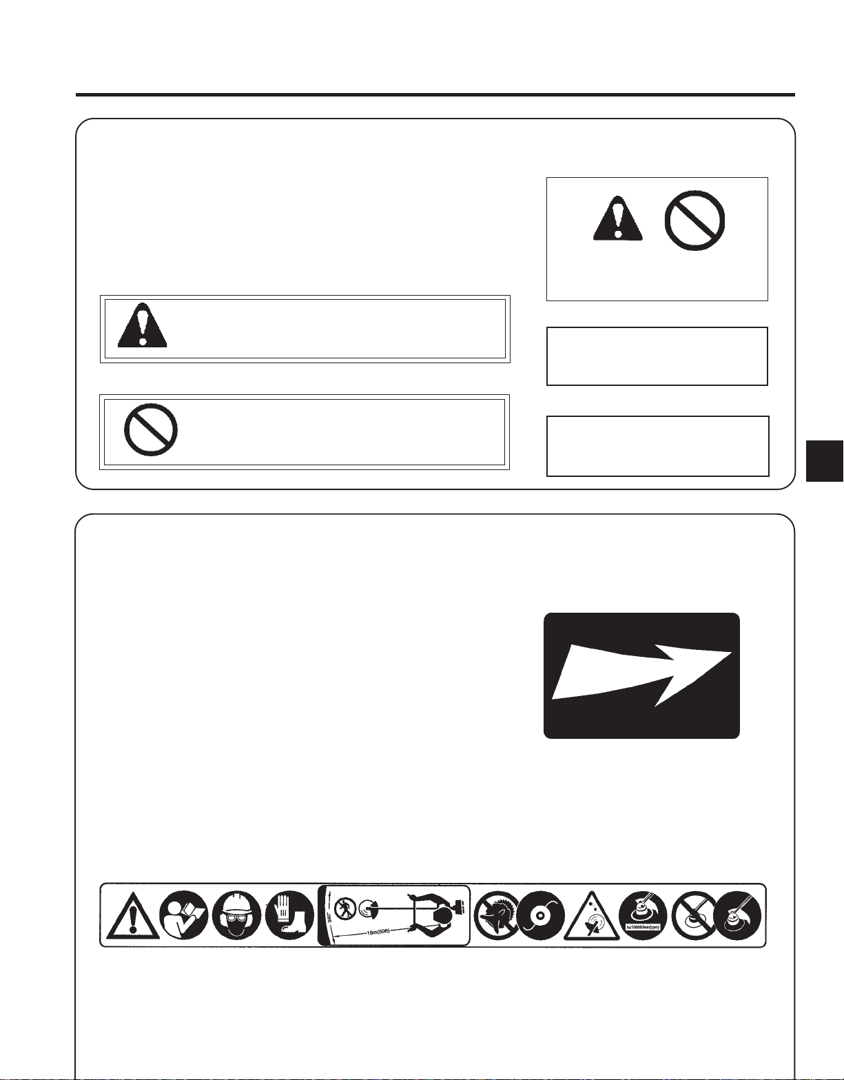
This symbol accompanied by the words WARNING and
DANGER calls attention to an act or condition that can lead to
serious personal injury to operator and bystanders.
IMPORTANT
IMPORTANT The enclosed message
provides information necessary for the
protection of the unit.
3
NOTE
The circle with the slash symbol means whatever is shown
within the circle is prohibited.
SAFETY
DECALS
Locate these safety decals on your unit. The complete unit illustration
found in the "DESCRIPTION" section, will help you locate them. Make
sure the decals are legible and that you understand and follow the
instructions on them. If a decal cannot be read, a new one can be ordered
from your ECHO Dealer.
NOTE This enclosed message provides
tips for use, care and maintenance of the
unit.
Debris Shield Decal
P/N 89018623760
Shaft Decal
P/N 89061763630
Page 4
4
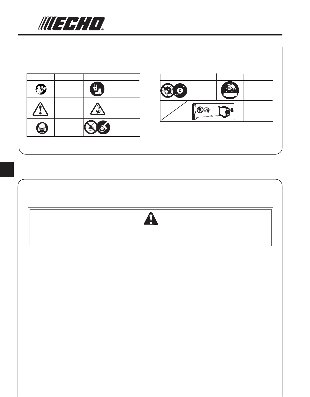
INTERNA TIONAL SYMBOLS
Symbol form/shape
Symbol
description/application
Carefully read the
operator’s manual
Safety alert
Wear eyes, ears and
head protection
Symbol form/shape
SAFETY INSTRUCTIONS
PERSONAL
CONDITION AND SAFETY EQUIPMENT
Symbol
description/application
Wear foot protection
and gloves
Warning!
Thrown objects!
Usage without shield
not permitted
Symbol form/shape
Symbol
description/application
DO NOT USE
BLADES - Line
Head Only
Symbol form/shape
ns10000/min
(rev/min)
Symbol
description/application
The maximum speed of
the cutting attachment
shaft in r/min
Keep bystanders away
15m
W ARNING DANGER
Trimmer/Brush Cutter users risk injury to themselves and others if the trimmer/brush cutter is used improperly
or safety precautions are not followed. Proper clothing and safety gear must be worn when operating a
trimmer/brush cutter.
Physical Condition
Your judgment and physical dexterity may not be good:
• if you are tired or sick,
• if you are taking medication,
• if you have taken alcohol or drugs.
Operate unit only if you are physically and mentally well.
Eye Protection
Wear eye protection that meets ANSI Z87.1 or CE
requirements whenever you operate the unit.
Hand Protection
Wear no-slip, heavy duty work gloves to improve your
grip on the unit handles. Gloves also reduce the transmission of machine vibration to your hands.
Hearing Protection
ECHO recommends wearing hearing protection whenever
unit is used.
Proper Clothing
Wear snug fitting, durable clothing;
• Pants should have long legs, shirts with long sleeves.
• DO NOT WEAR SHORTS,
• DO NOT WEAR TIES, SCARVES, JEWELRY.
Wear sturdy work shoes with non-skid soles;
• DO NOT WEAR OPEN TOED SHOES,
• DO NOT OPERATE UNIT BAREFOOTED.
Hot Humid Weather
Heavy protective clothing can increase operator fatigue
which may lead to heat stroke. Schedule heavy work for
early morning or late afternoon hours when temperatures
are cooler.
Page 5
PAS TRIMMER ATTACHMENT
OPERATOR'S MANUAL
5
EXTENDED
OPERATION/EXTREME CONDITIONS
Vibration and Cold
It is believed that a condition called Raynaud’s Phenomenon, which
affects the fingers of certain individuals, may be brought about by
exposure to vibration and cold. Exposure to vibration and cold may
cause tingling and burning sensations, followed by loss of color and
numbness in the fingers. The following precautions are strongly
recommended, because the minimum exposure which might trigger the
ailment is unknown.
• Keep your body warm, especially the head, neck, feet, ankles,
hands, and wrists.
• Maintain good blood circulation by performing vigorous arm
exercises during frequent work breaks, and also by not smoking.
• Limit the hours of operation. Try to fill each day with jobs where
operating the trimmer or other hand-held power equipment is not
required.
• If you experience discomfort, redness and swelling of the fingers
followed by whitening and loss of feeling, consult your physician
before further exposing yourself to cold and vibration.
Repetitive Stress Injuries
It is believed that overusing the muscles and tendons of the fingers,
hands, arms and shoulders may cause soreness, swelling, numbness,
weakness, and extreme pain in those areas. Certain repetitive hand
activities may put you at a high risk for developing a Repetitive Stress
Injury (RSI). An extreme RSI condition is Carpal Tunnel Syndrome
(CTS), which could occur when your wrist swells and squeezes a vital
nerve that runs through the area. Some believe that prolonged exposure
to vibration may contribute to CTS. CTS can cause severe pain for
months or even years.
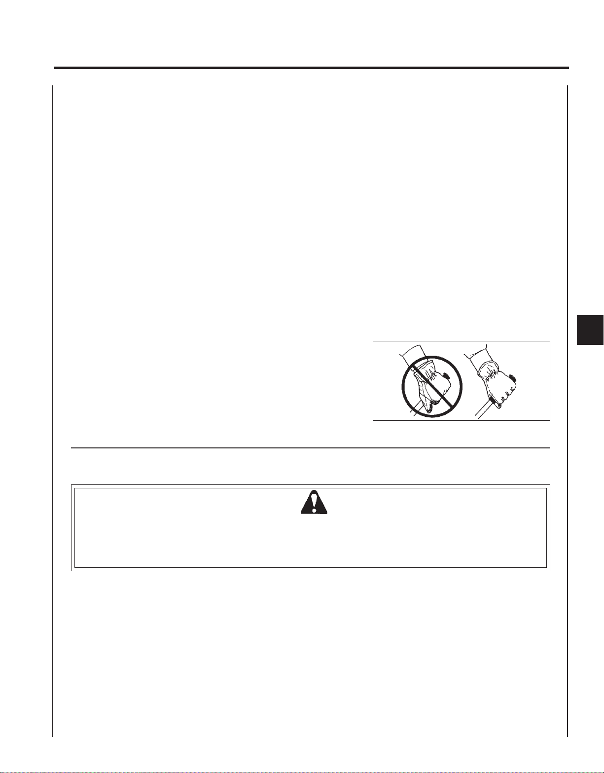
To reduce the risk of RSI/CTS, do the
following:
• Avoid using your wrist in a bent, extended, or twisted position. Instead, try to
maintain a straight wrist position. Also,
when grasping, use your whole hand, not
just the thumb and index finger.
• Take periodic breaks to minimize repetition
and rest your hands.
• Reduce the speed and force with which
you do the repetitive movement.
• Do exercises to strengthen the hand and
arm muscles.
• Immediately stop using all power equipment and consult a doctor if you feel
tingling, numbness, or pain in the fingers,
hands, wrists, or arms. The sooner RSI/
CTS is diagnosed, the more likely permanent nerve and muscle damage can be
prevented.
EQUIPMENT
W ARNING DANGER
Use only ECHO approved attachments. Serious injury may result from the use of a non-approved attachment
combination. ECHO, INC. will not be responsible for the failure of cutting devices, attachments or accessories which
have not been tested and approved by ECHO. Read and comply with all safety instructions listed in this manual and
safety manual.
• Check unit for loose/missing nuts, bolts, and screws. Tighten and/or
replace as needed.
• Inspect shield for damage and ensure that the cut-off knife issecurely
in place. Replace if either is damaged or missing.
• Check that the cutting attachment is firmly attached and in safe
operating condition.
• Check that front loop handle and shoulder strap/ or shoulder/
waist harness are adjusted for safe, comfortable operation. See
Assembly Section for proper adjustment.
Page 6

6
SAFE OPERATION
W ARNING DANGER
Do not operate this product indoors or in inadequately ventilated
areas. Engine exhaust contains poisonous emissions and can cause
serious injury or death.
Provide Safety And Operating Instructions To All Operators
• Provide all users of this equipment with the Operator's Manual and
Safety Manual for instructions on Safe Operation.
Keep A Firm Grip
• Hold the front and rear handles with both hands with thumbs and
fingers encircling the handles
Keep A Solid Stance
• Maintain footing and balance at all times. Do not stand on slippery,
uneven or unstable surfaces. Do not work in odd positions or on
ladders. Do not over reach.
Avoid Hot Surfaces
• Keep exhaust area clear of flammable debris. Avoid contact during
and immediately after operation.
DESCRIPTION
After opening the carton, check for damage. Immediately notify your retailer or ECHO Dealer of damaged or missing
parts. Use the contents list to check for missing parts.
CONTENTS
1 - PAS Trimmer Attachment
1 - Operator's Manual
1 - Locking Tool
1 - Plastic Debris Shield
1 - Nylon Trimmer Head
1 - Safety Goggle
1 - Shield Plate
3 - 5mm x 15mm Screws (shield mounting)
Page 7

PAS TRIMMER ATTACHMENT
OPERATOR'S MANUAL
7
4
1. LOWER DRIVE SHAFT ASSEMBLY - Includes the Debris Shield Assembly, Gear Housing assembly, Flexible Drive
Cable, Nylon Cutter Head and Safety Decals.
2. PLASTIC DEBRIS SHIELD ASSEMBLY - Included in plastic bag (co-pack). MUST be installed on unit before use,
see Assembly Instructions. Shield assembly includes the Cut-Off Knife and Safety Decal. Mounts on the Gear
Housing Assembly just above the cutting attachment. Helps protect the operator by deflecting debris produced
during the trimming operation. This shield must be replaced with the steel shield for blade use.
3. CUT-OFF KNIFE - Trims line to the correct length: 127mm from head to end of line after head is tapped on the ground
during operation and the line advances. If trimmer is operated without a cut-off knife the line will become too long. If
the line is more than the listed length the operating speed will slow, the engine overheat and engine damage may
occur.
4. NYLON CUTTER HEAD - Contains replaceable nylon trimming line that advances when the trimmer head is tapped
against the ground while the head is turning at normal operating speed.
5. OPERATOR'S MANUAL - Included in plastic bag (co-pack). Read before operation and keep in a safe place for future
reference, i.e., operation, maintenance, storage and specifications.
5
SPECIFICATIONS
PAS Trimmer Attachment
MODEL ----------------------------------------------------- PAS Trimmer Attachment
Shaft Length ------------------------------------------------ 870 mm (34.3 in.)
Attachment Width ----------------------------------------- 178 mm (7.0 in.)
Attachment Height ---------------------------------------- 255 mm (10.0 in.)
Weight (dry) w/line head --------------------------------- 1.43 kg (3.15 lb.)
Drive Shaft -------------------------------------------------- 1/4" Flex Shaft
Direction of Rotation -------------------------------------- Counter clockwise viewed from the top
Cutter Head -------------------------------------------------Nylon line head (2-lines) with .095" Cross Fire™ Line
Line Capacity 6 m (20 ft.)
NOTE Install U-handle and metal shield when using metal blade.
Page 8

8
ASSEMBLY
POWER
Tools Required: None
Parts Required: PAS or SRM-SB Power Head w/Shaft & Coupling.
1 . Set Power Head/Shaft Assembly on a level surface.
2 . Pull locator pin (A) out, and turn counter-clockwise 1/4 turn to lock-
out position.
3 . Carefully fit attachment drive shaft assembly into coupler (B) to decal
assembly line (C), making sure that the inner lower drive shaft
engages into the square upper drive shaft socket.
NOTE
Earlier model Power Heads may have shorter couplings. Short
couplings fit flush to decal point (E). New couplings are 120 mm
(4-3/4 in.) long, and fit flush to line (C).
NOTE
Lower bearing housing and head assembly must be in line with the
engine.
HEAD SHAFT/LOWER SHAFT ASSEMBL Y
B
D
A
B
D
A
4 . Rotate locator pin (A) 1/4 turn clockwise to engage lower shaft
hole. Insure locator pin is fully engaged by twisting lower drive
shaft. Locator pin should snap flush in coupler. Full engagement will
prevent further shaft rotation.
5 . Secure lower shaft assembly to coupler by tightening clamping
knob (D).
D
C
E
Page 9

PAS TRIMMER ATTACHMENT
PLASTIC SHIELD INSTALLATION
(For Nylon Line Operation)
Tools Required: Screwdriver.
Parts Required: Plastic Shield, Shield Plate, three (3) 5 mm x 15 mm
screws.
NOTE
The plastic shield is for use with the Nylon Line Head only.
1. Snap the shield on the bottom of the bearing housing flange.
2 . Place shield plate on shield, align holes and install three (3) screws.
OPERATOR'S MANUAL
9
NYLON LINE HEAD INSTALLATION
Tools Required: Head Locking Tool
Parts Required: Nylon Line Head.
1 . Align locking hole in upper plate (B) with notch in edge of gear
housing and insert head locking tool (A).
2 . Remove plastic sleeve from P.T.O. shaft (C).
3 . Be sure upper plate (B) remains on P.T.O. shaft.
4 . Thread line head onto P.T.O. shaft by turning it counter clockwise
until head is tight against upper plate (B).
5 . Remove locking tool (B).
A
C
B
Page 10

10
OPERATION
W ARNING DANGER
The cutting attachment should not rotate at idle. If attachment
rotates, readjust carburetor according to "Carburetor Adjustment"
instructions in this manual or see your ECHO Dealer, otherwise
serious personal injury may result.
NOTE
Refer to the power head Operator's Manual for proper and safe
operating techniques.
W ARNING DANGER
Inspect starting area for hazards such as rocks, glass, debris etc.
which could be contacted by the cutting attachment when starting.
Keep helpers and bystanders at least 15 m (50 ft.) from starting
area, otherwise serious personal injury may result.
MAINTENANCE
Your ECHO unit is designed to provide many hours of trouble-free service. Regular scheduled maintenance will help your
unit achieve that goal. If you are unsure or are not equipped with the necessary tools, you may want to take your unit to
an ECHO Service Dealer for maintenance. To help you decide whether you want to DO-IT-YOURSELF or have the ECHO
Dealer do it, each maintenance task has been graded. If a task is not listed, see your ECHO Dealer for repairs.
SKILL LEVELS
Level 1 = Easy to do. Most required tools come with unit.
Level 2 = Moderate difficulty. Some specialized tools may be required.
Level 3 = Experience required. Specialized tools are required. ECHO recommends
that the unit be returned to your ECHO dealer for service.
MAINTENANCE INTERVALS
Component/System Maintenance Procedure Skill Level Frequency
Drive Shaft Grease 1 Every 25 hours of use
Gear Housing Grease 1 Every 50 hours of use
Screws/Nuts/Bolts Inspect/Tighten/Replace 1 Before each use
Page 11

LUBRICA TION
Level 1.
Tools Required: 8 mm Open End Wrench, Screwdriver, Clean Rag
Parts Required: Lithium Base Grease.
Gear Housing
1 . Clean all loose debris from gear box.
2 . Remove plug (A) and check level of grease.
3 . Add grease if necessary, DO NOT over fill.
PAS TRIMMER ATTACHMENT
OPERATOR'S MANUAL
11
4 . Install plug (A).
Drive Shaft (Lower)
IMPORTANT
Lower and upper drive shaft must be lubricated with high temperature automotive grease every 25 hours of operation, otherwise drive
shaft assembly overheating and failure can result.
1 . Loosen two (2) screws (B) and remove center locating screw (C).
Pull gear box and shield from drive shaft housing.
2 . Pull flexible cable from the drive shaft housing, wipe clean and
re-coat with a thin coating [15 ml (1/2 oz.)] of Lithium Base Grease.
3 . Slide the flexible cable back in the drive housing. DO NOT get
dirt on the flex cable.
4. Install the gear housing and shield assembly.
IMPORTANT
Flat edge of washers (D) must be against drive shaft.
A
D
Page 12

12
NYLON LINE REPLACEMENT
Level 1.
Parts Required: ECHO 0.095 in. Nylon Trimmer Line 6 m (20 ft.) long.
1. Shut engine off. Lay unit on the ground with head assembly up.
2 . Hold drum (A) and turn spool (B) CW (clockwise) until it stops.
Pull spool from drum. DO NOT push in on spool when turning.
3 . Use one piece of new nylon line (C) 6 m (20 ft.) long and thread
through the molded loop (D) on the spool. Pull line tight and
adjust so one end is 15 cm (6 in.) longer than the other.
4 . Hold the spool, opening toward you. Place index finger between
the two strands and wind line, tightly and evenly, in direction of
arrow (E) marked "CC".
Page 13

5 . Stop when approximately 15-20 cm (6-8 in.) line (C) remains and
place ends of line in notches (F) in spool (B).
6 . Feed ends of line through housing eyelets (G) and place spool (B)
over drive (H). Align pegs (I) on drive with notches in spool, and
push spool into drum.
PAS TRIMMER ATTACHMENT
OPERATOR'S MANUAL
F
H
I
G
I
13
7 . Pull on both lines until they come free from notches (F) in spool.
8 . Hold drum (A) firmly and turn spool (B) CCW (counterclockwise)
until it stops. DO NOT push in on spool when turning.
9 . Pull both lines out and trim to cut-off knife length.
G
Page 14

14
DECLARATION “CE” OF CONFORMITY
The undersigned manufacturer:
KIORITZ CORPORA TION
7-2 SUEHIROCHO 1-CHOME
OHME ; TOKYO 198-871 1
JAPAN
declares that the hereunder specified new unit:
PRO ATTACHMENT
Brand :ECHO
Type : PAS-2400
assembled by:
ECHO, INCORPORA TED
400 Oakwood Road
Lake Zurich, Ilinois 60047-1564
U.S.A.
complies with:
*the requirements of Directive 98/37/EC (1998)
*the requirements of Directive 89/336/EEC
(use of harmonized standards EN 50081-1, EN 50082-1, EN 55014 & EN 55022)
*the requirements of Directive 2002/88/EC
*the requirements of Directive 2000/14/EC
Conformity assessment procedure followed ANNEX V
Measured sound power level :106 dB(A)
Guaranteed sound power level : 109 dB(A)
SERIES
Tokyo,
May 1st 2004
GB
Page 15

NOTES
PAS TRIMMER ATTACHMENT
OPERATOR'S MANUAL
15
Page 16

KIORITZ CORPORATION
7-2 SUEHIROCHO 1-CHOME, OHME, TOKYO, 198-8711, JAPAN
PHONE: 81-428-32-6118 FAX: 81-428-32-6145
ECHO, INCORPORATED
400 OAKWOOD ROAD
LAKE ZURICH, IL 60047
GB
X770-000 151
X770227-1902
 Loading...