

Page 1

IzoTTM
NodeBuilder
Develop hardware devices and software applications using
Echelon's Series 6000, 5000, and 3100 chips and Smart
User’s Guide
Transceivers.
078-0516-01A
Page 2

Echelon, LON, LonWorks, Neuron, 3120, 3150, Digital
Home, i.LON, IzoT, FTXL, LonScanner, LonSupport, LNS,
LonMaker, L
ONMARK, LonPoint, LonTalk, NodeBuilder,
ShortStack, and the Echelon logo are trademarks of
Echelon Corporation that may be registered in the
United States and other countries.
Other brand and product names are trademarks or
registered trademarks of their respective holders.
Neuron
Chips and other OEM Products were not
designed for use in equipment or systems which involve
danger to human health or safety or a risk of property
damage and Echelon assumes no responsibility or
liability for use of the Neuron
Chips or LonPoint Modules
in such applications.
Parts manufactured by vendors other than Echelon and
referenced in this document have been described for
illustrative purposes only, and may not have been tested
by Echelon. It is the responsibility of the customer to
determine the suitability of these parts for each
application.
ECHELON MAKES NO REPRESENTATION, WARRANTY, OR
CONDITION OF ANY KIND, EXPRESS, IMPLIED, STATUTORY,
OR OTHERWISE OR IN ANY COMMUNICATION WITH YOU,
INCLUDING, BUT NOT LIMITED TO, ANY IMPLIED
WARRANTIES OF MERCHANTABILITY, SATISFACTORY
QUALITY, FITNESS FOR ANY PARTICUL AR PURP O SE ,
NONINFRINGEMENT, AND THEIR EQUIVALENTS.
No part of this publication may be reproduced, stored in
a retrieval system, or transmitted, in any form or by any
means, electronic, mechanical, photocopying,
recording, or otherwise, without the prior written
permission of Echelon Corporation.
Printed in the United States of America.
Copyright ©1997–2014 by Echelon
Corporation.
Echelon Corporation
www.echelon.com
ii
Page 3

CONTENTS
Preface ................................................................................................... ix
Purpose ........................................................................................................... x
Audience .......................................................................................................... x
Hardware Requirements .................................................................................. x
Content ............................................................................................................ x
Related Manuals ............................................................................................. xi
For More Information and Technical Support ................................................. xii
1 Introduction ....................................................................................... 1
Introduction to the IzoT NodeBuilder Tool ....................................................... 2
New Features in the IzoT NodeBuilder Tool ................................................... 2
LonTalk/IP Support ................................................................................... 2
BACnet/IP Support .................................................................................... 3
Series 6000 Chip Support ......................................................................... 3
Transient Functions and Automatic Memory Maps .................................. 3
FT 6000 EVB Evaluation Board ................................................................ 4
Extended Address Table ........................................................................... 4
Network Variables Up To 228 Bytes ......................................................... 4
Neuron C Version 2.3 Enhancements ...................................................... 5
What's Included with the IzoT FT 6000 EVK ................................................... 6
IzoT NodeBuilder Development Tool ........................................................ 6
FT 6000 EVB Evaluation Boards .............................................................. 7
IzoT Commissioning Tool ......................................................................... 8
IzoT Network Services Server .................................................................. 8
IzoT Router ............................................................................................... 8
IzoT Plug-in for Wireshark ........................................................................ 8
Introduction to NodeBuilder Device Development and Network Integration ... 9
Channels ................................................................................................... 9
Routers ...................................................................................................... 9
Applications ............................................................................................. 10
Program IDs ............................................................................................ 10
Network Variables ................................................................................... 11
Configuration Properties ......................................................................... 12
Functional Blocks .................................................................................... 13
Functional Profiles................................................................................... 13
Hardware Templates ............................................................................... 14
Neuron C ................................................................................................. 14
Device Templates ................................................................................... 14
Device Interface Files.............................................................................. 14
Resource Files ........................................................................................ 14
Targets .................................................................................................... 15
2 Installing the IzoT NodeBuilder Development Tool ...................... 17
Installing the IzoT FT 6000 EVK .................................................................... 18
Installing the IzoT NodeBuilder Software ................................................ 18
3 IzoT NodeBuilder Quick-Start Exercise ......................................... 25
IzoT NodeBuilder Quick-Start Exercise ......................................................... 26
Step 1: Creating an IzoT NodeBuilder Project ........................................ 26
Step 2: Creating a NodeBuilder Device Template .................................. 29
Step 3: Defining the Device Interface and Creating its Neuron C
Application Framework ........................................................................... 33
Step 4: Developing the Device Application ............................................. 38
IzoT NodeBuilder User's Guide iii
Page 4

FT 6000 Evaluation Boards .............................................................. 39
LTM-10A Platform and Gizmo 4 I/O Board ...................................... 41
Step 5: Compiling, Building, and Downloading the Application .............. 42
Step 6: Testing the Device Interface ....................................................... 46
Step 7: Debugging the Device Application ............................................. 48
Step 8: Connecting and Testing the Device in a Network ...................... 54
Additional Device Development Steps .................................................... 60
Creating an IzoT CT Stencil ............................................................. 60
Creating an IzoT Device Plug-in ....................................................... 64
Developing an HMI ........................................................................... 65
Creating a Device Installation Application ........................................ 65
Applying for LONMARK Certification .................................................. 67
4 Creating and Opening IzoT NodeBuilder Projects ....................... 69
Introduction to the NodeBuilder Project Manager ......................................... 70
Using the Project Pane ........................................................................... 71
Creating a NodeBuilder Project ..................................................................... 72
Creating a NodeBuilder Project from IzoT CT ........................................ 73
Creating a NodeBuilder Project from the NodeBuilder Project Manager 73
Creating a NodeBuilder Project from the New Device Wizard................ 76
Opening a NodeBuilder Project ..................................................................... 78
Opening a NodeBuilder Project from the IzoT Commissioning Tool ...... 78
Opening a NodeBuilder Project from the NodeBuilder Project Manager 80
Copying NodeBuilder Projects ....................................................................... 81
Using the IzoT Commissioning Tool to Backup and Restore a
NodeBuilder Project ................................................................................ 81
Manually Copying NodeBuilder Project Files .......................................... 84
Copying NodeBuilder Device Templates ....................................................... 85
Copying User-Defined Resource Files .......................................................... 86
Viewing and Printing NodeBuilder XML Files ................................................ 86
5 Creating and Using Device Templates .......................................... 88
Introduction to Device Templates .................................................................. 89
Creating Device Templates ........................................................................... 89
Starting the New Device Template Wizard ............................................. 89
Specifying the Device Template Name ................................................... 90
Specifying the Program ID ...................................................................... 91
Specifying Target Platforms .................................................................... 96
Managing and Editing Device T em plates ...................................................... 98
Managing Device Templates .................................................................. 98
Viewing and Editing Device Templates................................................... 99
Viewing Device Template Components ................................................ 100
Managing Development and Release Targets ..................................... 102
Setting Device Template Target Properties: Compiler ................... 103
Setting Device Template Target Properties: Linker ....................... 106
Setting Device Template Target Properties: Exporter .................... 107
Setting Device Template Target Properties: Configuration ............ 109
Inserting a Library into a NodeBuilder Device Template ...................... 111
Using Hardware Templates ......................................................................... 114
Creating Hardware Templates .............................................................. 115
Editing Hardware Templates ................................................................. 117
Setting Hardware Properties .......................................................... 117
Setting Memory Properties ............................................................. 120
5000 Series Chips .................................................................... 121
6000 Series Chips .................................................................... 122
3150 Neuron Core ................................................................... 122
iv Preface
Page 5

3120 and 3170 Neuron Core ................................................... 122
Setting the Hardware Template Description ................................... 122
6 Defining Device Interfaces and Creating their Neuron C Application
Framework .......................................................................................... 124
Introduction to Device Interfaces ................................................................. 125
Starting the Code Wizard ...................................................................... 125
Using the Resource Pane............................................................... 126
Introduction to Resource File Sets ........................................... 127
Introduction to Resources ........................................................ 128
Using the NodeBuilder Resource Editor .................................. 130
Using the Program Interface Pane ................................................. 130
Defining the Device Interface ................................................................ 132
Adding Functional Blocks ............................................................... 135
Using Large Functional Block Arrays ....................................... 138
Editing Mandatory Network Variables ............................................ 138
Editing Mandatory Configuration Properties................................... 145
Implementing Optional Network Variables ..................................... 151
Implementing Optional Configuration Properties ........................... 153
Adding Implementation-specific Network Variables ....................... 155
Adding Implementation-specific Configuration Properties ............. 158
Setting Initial Values for Network Variables and
Configuration Properties ................................................................. 161
Setting Initial Values for Structured Data Types ...................... 162
Setting Initial Values for Enumerations .................................... 164
Setting Initial Values for Floating Point and s32 Data Types ... 165
Using Changeable-Type Network Variables .................................. 166
Generating Code with the Code W izard ............................................... 167
Files Created by the Code Wizard ................................................. 167
Using Code Wizard Templates .................................................... 170
Version 3 Templates ................................................................ 170
Version 2 Templates ................................................................ 170
Version 1 Templates ................................................................ 171
Creating the Device Application ..................................................... 171
7 Developing Device Applications .................................................. 173
Introduction to Neuron C ............................................................................. 174
Unique Aspects of Neuron C ................................................................ 174
Neuron C Variables ............................................................................... 176
Neuron C Variable Types ............................................................... 176
Neuron C Storage Classes ............................................................. 176
Variable Initialization ....................................................................... 177
Neuron C Declarations ................................................................... 177
Introduction to Neuron C Code Editing ........................................................ 178
Modifying Neuron C Code Generated by the Code Wizard .................. 179
Code Commands ............................................................................ 179
Code Guidelines ............................................................................. 180
Add I/O and Timer Declarations ............................................... 180
Add when-tasks Responding to I/O and Timer Events ............ 181
Add interrupt-tasks Responding to Interrupt Requests ............ 181
Add Code to when(nv_update_ occ ur s( <nv>)) when-task
of Functional Blocks with Input NVs......................................... 181
Share Code with filexfer.nc when Handling Explicit
Messages on a Device Implementing FTP .............................. 181
Ignore NCC#310 and NC#463 Compiler Warnings ................. 181
Implementing Changeab le-Type Network Variables ...................... 181
IzoT NodeBuilder User's Guide v
Page 6

Neuron C Version 2 Features Not Supported by the Code Wizard 183
Message Tags.......................................................................... 183
I/O Models ................................................................................ 183
Network Variables .................................................................... 183
Configuration Properties .......................................................... 183
when() clauses ......................................................................... 184
LONMARK Style ......................................................................... 184
Director Functions .................................................................... 184
Interrupt Tasks ......................................................................... 184
Using the NodeBuilder Editor ...................................................................... 184
Using Syntax Highlighting ..................................................................... 185
Searching Source Files ......................................................................... 185
Searching a Single File for a String ................................................ 185
Replacing Text ................................................................................ 186
Searching Multiple Files for a String ............................................... 186
Using Bookmarks .................................................................................. 189
Setting Editor Options ........................................................................... 189
8 Building and Downloading Device Applications ........................ 191
Introduction to Building and Downloading Applications .............................. 192
Building an Application Image ..................................................................... 192
Excluding Targets from a Build ............................................................. 197
Cleaning Build Output Files .................................................................. 197
Viewing Build Status ............................................................................. 198
Setting Build Options............................................................................. 200
Downloading an Application Image ............................................................. 201
Programming 5000 and 6000 Off-chip Memory .................................... 203
Programming 5000 and 6000 Series Chips In-Circuit .................... 203
Programming 3150 Off-chip Memory .................................................... 208
Programming 3150 On-chip Memory .................................................... 209
Programming 3120 and 3170 On-chip Memory .................................... 210
Programming PL 3120 and PL 3170 Smart Transceiver
Parameters ..................................................................................... 210
Upgrading Device Applications ............................................................. 211
Adding and Managing Target Devices ........................................................ 211
Adding a Target Device with the IzoT Commissioning Tool ................. 211
Adding a Target Device with the NodeBuilder Project Manager .......... 215
Managing Target Devices ..................................................................... 217
Editing Target Device Settings .............................................................. 218
9 Testing a NodeBuilder Device Using the IzoT Commissioning Tool 221
Introduction to Testing NodeBuilder Devices .............................................. 222
Monitoring and Controlling Node Bu il der De vic es ................................. 222
Using the Data Point Shape ........................................................... 222
Using the LonMaker Browser ......................................................... 224
Connecting NodeBuilder Devices ......................................................... 227
10 Debugging a Neuron C Application ............................................. 233
Introduction to Debugging ........................................................................... 234
Starting the NodeBuilder Debug ger ...................................................... 234
Using the Debugger Toolbar ................................................................. 236
Stopping an Application ........................................................................ 237
Halting an Application ..................................................................... 238
Running to the Cursor .................................................................... 238
Setting and Using Breakpoints ....................................................... 238
Stepping Through Applications ............................................................. 239
vi Preface
Page 7

Debugging Interrupts for 5000 or 6000 Series chips ............................ 239
Using Statement Expansion .................................................................. 239
Using the Watch List Pane .................................................................... 239
Using the Call Stack Pane .................................................................... 243
Using the Debug Device Manager Pane............................................... 243
Peeking and Poking Memory ................................................................ 244
Executing Code in Development Targets Only ..................................... 245
Using the Debug Error Log Tab ............................................................ 245
Setting Debugger Options ..................................................................... 245
Appendix A Using the Command Line Project Make Facility ......... 249
Using the NodeBuilder Command Line Project Make Facility ..................... 250
Appendix B Using Source Control With a NodeBuilder Project ..... 253
Using Source Control with a NodeBui lder Pr oj ect ....................................... 254
Appendix C Glossary ........................................................................ 257
Appendix D NodeBuilder Software License Agreement ................. 271
IzoT NodeBuilder User's Guide vii
Page 8

viii Preface
Page 9

Preface
The IzoT™ NodeBuilder® Development Tool is a complete hardware and software
platform that is used to develop applications for Neuron Chips and Echelon Smart
Transceivers. The IzoT NodeBuilder tool lets you create, debug, test, and maintain
IzoT and LONWORKS devices. It includes a suite of device development software
that you can use to develop device applications, and hardware platforms that you can
use to build and test prototype and production devices.
IzoT NodeBuilder User's Guide ix
Page 10

Purpose
This document describes how to use the IzoT NodeBuilder tool to develop IzoT and LONWORKS
device applications and build and test prototype and production IzoT and L
ONWORKS devices.
Audience
This guide is intended for device and system designers with an understanding of control networks.
Hardware Requirements
Requirements for co mputers running the IzoT Nod eBuild e r tool are listed below:
• Microsoft
XP 32-bit. Echelon recommends that you install the latest service pack available from Microsoft
for your version of Windows.
• An Intel® Pentium
selected version of Windows.
• 300 to 550 megabytes (MB) free hard-disk space, plus the minimum Windows requirements for
the selected version of Windows.
®
Windows. Windows 8 64-bit and 32-bit, or Windows 7 64-bit and 32-bit, or Windows
®
or compatible processor meeting the minimum Windows requirements for the
o The IzoT NodeBuilder tool requires 100 MB of free space.
o The IzoT Commissioning Tool, which is req uire d to install the IzoT NodeB uilde r tool,
requires 172 MB of free space.
o Microsoft .NET Framework 3.5 SP1, which is required to run the IzoT NodeBuilder tool,
requires 30 MB of free space. This is not included and must be downloaded separately.
• 512 MB RAM minimum.
• DVD-ROM drive.
• 1024x768 or higher-resolution display with at least 256 colors.
• Mouse or compatible pointing device.
Content
This guide includes the following content:
• Introduction. Lists the new fea tures in the IzoT NodeBuilder tool, summarizes the components
included with the IzoT NodeBuilder tool, and provides an overview of IzoT NodeBuilder device
development and network integration.
• Installing the IzoT NodeBuilder Development Tool. Describes how to get started with your IzoT
NodeBuilder tool, including how to install the IzoT NodeBuilder software and connect the IzoT
FT 6000 EVK hardware.
• IzoT NodeBuilder Quick-Start Exercise. Demonstrates how to create an Iz oT or L
device using the IzoT NodeBuilder tool.
ONWORKS
• Creating and Opening NodeBuilder Projects. Describes how to create, open, and copy
NodeBuilder projects, and explains how to copy NodeBuilder projects and NodeBuilder device
templates to another computer.
• Creating and Using Device Templates. Describes how to use the New Device Template wizard in
the NodeBuilder Project Manager to create, manage, and edit NodeBuilder device templates.
x Preface
Page 11

FT 6000 EVB Examples Guide
Describes how to run the Neuron C e xample applications
FT 6000 EVB Hardware Guide
Describes how to connect the FT 6000 EVBs, and describes the
Introduction to the LONW
Provides a high-level introduction to LONW
networks a nd
ools and components that are used for developing, installing,
OpenLNS Plug-in Program mer’s
Describes how to write plug-ins using .NET progra mming
Explains how to manage development and release targets and insert libraries into a device
template. Describes how to use the Hardware Template Editor to create and edit hardware
templates.
• Defining Device Interfaces and Creating their Neuron C Application Framework. Describes how
to use the NodeBuilder Code Wizard to define your device interface and generate Neuron C code
that implements it. Explains how to start the NodeBuilder Code Wiz a rd, how to add functional
blocks, network variables, and configuration properties to your device template, and how to create
the Neuron C framework for your device interface.
• Developing Device Applications. Provides an overview of the Neuron C Version 2.3
programming language. Describes how to edit the Neuron C source code generated by the
NodeBuilder Code Wiza rd to implement your device functionality. Exp la ins how to use the
NodeBuilder Editor to edit, search, and bookmark Neuron C code.
• Building and Downloading Device Applications. Describes how to compile Neuron C source
code, build an application image, and download the application image to a device. Explains how
to add target devices to a NodeBuilder project and how to manage them.
• Testing a NodeBuilder Device Using the IzoT Commissioning Tool. Describes how to use the
Data Point shape and IzoT Browser in the IzoT Commissioni ng Tool to monitor and control your
device. It explains how to use the IzoT Commissioning Tool to connect your IzoT NodeBuilder
device to other IzoT or L
• Debugging a Neuron C Application. Describes how the use the NodeBuilder debugger to
troubleshoot your Neuron C application.
ONWORKS devices in a network.
• Appendices. Provides information for using the command line project make facility and managing
an IzoTNodeBuilder project using a source control application. Also include s a glossary with
definitions for many terms commonly used with an IzoT NodeBuilder device development.
Note: Screenshots in this document were taken d uring the development of the IzoT NodeBuilder tool;
therefore, some images may vary slightly from the release version of the user interface.
Related Manuals
The documentation related to the IzoT NodeBuilder tool is provided as Adobe® PDF files and online
help files. The PDF files are installed in the Echelon NodeBuilder program folder when you install
the IzoT NodeBuilder tool. You can download the latest NodeBuilder documentation, including the
latest version of this guide, from Echelon’s Web site at www.echelon.com/docs.
The following manuals provide supp lemental information to the materia l in this guide. You can
download these documents from Echelon’s Web site at www.echelon.com.
( 078-0505-01)
(078-0504-01)
ORKS
Platform
(078-0183-01B)
included with the FT 6000 EVK on an FT 6000 EVB.
Neuron core, I/O devices, service pin and reset buttons and
LEDs, and jumper settings on the FT 6000 EVB hardware.
One or two FT 6000 EVBs are included with the IzoT FT 6000
EVK.
ORKS
the t
operating, and maintaining them.
Guide (078-0393-01A)
IzoT NodeBuilder User's Guide xi
languages s uch as C# and Visual Ba sic .NET
Page 12
IzoT Commissioning ToolUser’s
Describes how to use the IzoT Commissioing Tool to design,
LONMARK SNVT and SCPT Guide
Documents the standard network variable types (SNVTs),
IZOT Plug-in for WireShark Guide
Describes how to use the IzoT Plug-in for WireShark. This is
Neuron C Programmer’s Guide
Describes how to write programs using the Neuron® C Version
Neuron C Reference Guide
Provides reference information for writing programs using the
Neuron Tools Error Guide
Provides reference information for Neuron tool errors.
NodeBuilder Resource Edit or User’s
Describes how to use the NodeBuilder Resource Editor to create
The Americas
English
Echelon Corporation
Guide (078-0514-01)
(078-9511-01A)
( 078-0002-02I)
(078-0140-02G)
(078-0402-01D)
Guide (078-0194-01C)
commission, modify, and maintain LONWORKS networks.
standard configuration property types (SCPTs), and standard
enumeration types that you can declare in your applications.
the packet analyzer to monitor, analyze, and troubleshoot
network protocol problems
2.3 language.
Neuron C language.
and edit resource file sets and resources such as functional
profile templates, network variable types, and configuration
property types.
For More Information and Technical Support
The NodeBuilder ReadMe document provides descriptions of known problems, if any, and their
workarounds. To view the NodeBuilder ReadMe, click Start, point to Programs, point to
NodeBuilder, and t hen select NodeBuilder ReadMe First. You can also find additional information
about the IzoT NodeBuilder tool at the NodeBuilder Web page at www.echelon.com/nodebuilder.
If you have technical questions that are not answered by this document, the NodeBuilder online help,
or the NodeBuilder ReadMe file, you can contact technical support. You can get free e-mail support
by sending your support questions to lonsupport@echelon.com To receive priority technical support
from Echelon, you can purchase support services from Eche lon or an Echelon support partner. See
www.echelon.com/support for more information on Eche lon support and training services .
You can also enroll in training classes at Echelon or an Echelon training center to learn more about
developing devices. You can find additional information abo ut d e vice development training at
www.echelon.com/training.
You can obtain technical support via phone, fax, or e-mail from your closest Echelon sup port center.
The contact information is as fo llows:
Region Languages Supported Contact Information
Japanese
Attn. Customer Support
550 Meri dian Avenue
San Jose, CA 95126
Phone (toll-free):
1-800-258-4LON (258-4566)
Phone: +1-408-938-5200
Fax: +1-408-790-3801
lonsupport@echelon.com
xii Preface
Page 13

Europe
English
Echelon Europe Ltd.
Japan
Japanese
Echelon Japan
China
Chinese
Echelon Greater China
Other Regio ns
English
Phone: +1-408-938-5200
Region Languages Supported Contact Information
German
French
Italian
English
Suite 12
Building 6
Croxley Green Busine s s Park
Hatters Lane
Watford
Hertfordshire WD18 8YH
United Kingdom
Phone: +44 (0)1923 430200
Fax: +44 (0)1923 430300
lonsupport@echelon.co.uk
Holland Hills Mori Tower, 18F
5-11-2 Toranomon, Minato-ku
Tokyo 105-0001
Japan
Phone: +81-3-5733-3320
Fax: +81-3-5733-3321
lonsupport@echelon.co.jp
Rm. 1007-1008, IBM Tower
Pacific Century Place
2A Gong Ti Bei Lu
Chaoyang District
Beijing 100027, China
Phone: +86-10-6539-3750
Fax: +86-10-6539-3754
lonsupport@echelon.com.cn
Japanese
Fax: +1-408-328-3801
lonsupport@echelon.com
IzoT NodeBuilder User's Guide xiii
Page 14

Page 15

Introduction
This chapter introduces the IzoT NodeBuilder Development Tool. It lists the new
features in the IzoT NodeBuilder tool, summarizes the components included with
theIzoTNodeBuilder tool, and provides an overview of NodeBuilder device
development and network integration.
1
IzoT NodeBuilder User's Guide 1
Page 16

Introduction to the IzoT NodeBuilder Tool
The IzoT NodeBuilder Development Tool is a complete hardware and software platform for
developing, debugging, testing, and maintainin g IzoT and L
6000 Processor and FT 6000 Smart Transceiver and all previous-generation Ser ies 5000 and Series
3100 chips. You can use the IzoT NodeBuilder tool to create many types of devices, including VAV
controllers, thermostats, washing machines, card-access readers, refrigerators, lighting ballasts, blinds,
and pumps. You can use these devic es in a variety of systems includin g building a nd lighting controls,
factory automation, energy management, and transportation.
You can use the IzoT NodeBuilder tool to do the following:
• View standard resource file definitions for standard network variable types (SNVTs), standard
configuration property (SCPTs), and standard functional profile templates (SFPTs).
• Create your own resource files with user-defined network variable types (UNVTs), user-defined
configuration property (UCPTs), and user-defined functional profile templates (UFPTs).
• Automatically generate Neuron C code that implements your device’s interface and provides the
framework for your device application.
• Edit your Neuron C c ode to implement your device’s func tionality.
• Compile, build, and download your application to a development platform or to your own devices.
ONWORKS devices based on the Neuron
• Test with prototype I/O hardware on either the FT 6000 EVB Evaluation Boards incl uded with the
FT 6000 EVK and available separately, or LTM-10A Platform and Gizmo 4 I/O Board included
with the NodeBuilder FX/PL tool and available separately, or use your own custom device to
build and test your own I/O hardware.
• Install your device into an IzoT or L
with other IzoT and L
ONWORKS devices.
ONWORKS network and test how your device interoperates
New Features in the IzoT NodeBuilder Tool
The IzoT NodeBuilder tool includes support for Echelon’s new Series 6000 chips (the term used to
collectively refer to the FT 6050 and FT 6010 Smart Transceivers and the Neuron 6050 Processor),
support for Echelon’s new FT 6000 EVB, support for the previous generation Series 5000 and Series
3100 chips, and the following key features:
• Support for the IzoT LonTalk/IP and BACnet/IP protocols
• Support for transient functions and automatically tuned memory maps
• Extended address table support with support for up to 254 address table entries
• Support for network variables up to 228 bytes (exceeding the previous limit of 31 bytes)
• Neuron C Version 2.3 Enhancements
The following sections describe these new features.
LonTalk/IP Support
The Series 6000 chips and firmware add support for the LonTalk/IP protocol. The LonTalk/IP
protocol is the control network pr otocol that implements IzoT Control Services. IzoT Control Services
are based on the L
native IP addressing at Layer 3, and link-specific protocols for Layers 1 and 2. The link-specific
protocols may implement compression of the Layer 3 packets depending on the requirements of the
underlying links. There are two modes for LonTalk/IP called Compatibility Mode and Enhanced
Mode. In Compatibility Mode LonTalk/IP devices can communicate with LonTalk devices directly
without the need for a r outer as long as they are on the same LonTalk-co mpatible c hannel. LonTalk/IP
ONMARK La yer 7 protocol, the ISO/IEC 14908-1 Layers 3 to 6 protocols, with
2 Introduction
Page 17

devices in Compatibility Mode can also communicate with LonTalk devices on different channels as
long as there is a route created between the channels with one or more IzoT routers. In Enhanced
Mode, LonTalk/IP devices cannot communicate with LonTalk devices, even with the use of IzoT
routers.
You can con figure the IzoT Router i ncluded with the FT 6000 EVK to operate in either Enhanced
Mode or Compatibility Mode. If you are developing devices that will potentially be used with devices
based on the Series 5000 or Series 3100 processors, select Compatibility Mode. If you are developing
devices that will exclusively be used with devices based on Series 6000 processors or other IzoTcompatible devices such as devices based on the IzoT Device Stack EX, select Enhanced Mode.
BACnet/IP Support
The Series 6000 chips and firmware add support for the BACnet/IP protocol. The BACnet/IP protocol
is the protocol that implements the BACnet services defined by ASHRAE and specified in ISO 164845, with native IP addressing at Layer 3, and link-specific protocols for Layers 1 and 2. The linkspecific protocols may implement compression of the Layer 3 packets depending on the requireme nts
of the underlying links .
Series 6000 Chip Support
The IzoT NodeBuilder software adds development support for the Series 6000 chips. Development for
Series 5000 and Series 3100 chips is also supported. An FT 6000 Evaluation Board hardware template
file (.NbHwt extension) is included, matching the FT 6000 EVB hardware.
See the FT 6000 EVK Hardware Guide for instructions to emulate the FT 6010 hardware with the FT
6050 Evaluation board. The FT 6010 Evaluation Board hardware template required for this emulation
is included .
An FT 6050 hardware template is included as an example of a typical hardware template for a generic
FT 6050 device.
The Neuron C compiler and its companion tools automatically take advantage of the Series 6000
chips’ features. For example, the Neuron C compiler automatically takes advantage of the extended
address table where available, and the dynamic host configuration protocol (DHCP) is automatically
enabled where supported.
Transient Functions and Automatic Memory Maps
The IzoT NodeBuilder software adds support for transient functions for applications targeting a Series
6000 chip. A transient function is loaded from serial flash memory on demand and automatically
managed by the Neuron firmware, allowing the application’s total code size to exceed the available
physical memory. Functions declared in Neuron C 2.3 compile to transient functions by default, while
when-tasks a nd interrupt-tasks always compile into resident code.
Individual functions can be made resident with the new Neuron C __resident keyword (note the
leading double underscore characters:
unsigned __resident add(unsigned a, unsigned b) {
return a+b;
}
See the Neuron C Programmer’s Guide for more details about resident and transient f unc tions.
To ease device development and ensure suitable space for transient functions, the Neuron C 2.3 tools
automatically size the memory map to suit the requirements of the Neuron firmware, the Series 6000
chips and your application combined. For these chips, it is no longer necessary to estimate the amount
of volatile memory (“RAM”), persistent data storage (“EEPROM”) or space needed for constant data
and code.
IzoT NodeBuilder User's Guide 3
Page 18

FT 6000 EVB Evaluation Board
The FT 6000 EVB is a complete 6000 Series IzoT and LONWORKS device that you can use to create
IzoT and L
external 10 MHz crystal (you can adjust the system’s internal clock speed from 5MHz to 80MHz), an
FT-X3 communication transformer, 64KB external serial EEPROM and flash memory devices, and a
3.3V power source. The FT 6000 EVB features a compact design that includes the follo wing I/O
devices that you can use to develop prototype and production devices and test the FT 6000 EVB
example applications:
• 4 x 20 character LCD
• 4-way joystick with center push button
• 2 push-button inp uts
• 2 LED outputs
• Light-level sensor
• Temperature sensor
The FT 6000 EVB Evaluation Board also includes EIA-232/TIA-232 (formerly RS-232) and USB
interfaces that you can use to connect the board to your development computer and perform
application-level d ebugging.
Each FT 6000 EVB also features a flash in-circuit programmer header that supports the SPI interface
for fast downloads when programming the external non -volatile memory of the FT 6050 Smart
Transceiver on the board.
ONWORKS devices. The FT 6000 EVB includes a FT 6050 S mart Transceiver with an
For more information on the FT 6000 EVB hardware, including detailed descriptions of its Neuron
core, I/O devices, service pin and reset buttons and LEDs, and jumper settings, see the FT 6000 EVB
Hardware Guide.
Extended Address Table
Series 6000 chips can support up to 254 address table records, subject to available system resources
(for example, RAM and EEPROM) and application requirements. The Series 5000 and Series 3100
chips are limited to a maximum of 15 address table entries.
Network Variables Up To 228 Bytes
Series 6000 chip support network variables up to 228 bytes in size. The Series 5000 and Series 3100
chips are limited to a maximum network variable size of 31 bytes.
Creating new applications or adding larger than 31 bytes network variables to existing applications is
completely transparent except when larger than 31 bytes network variables are added to existing
applications which also implement changeable-type applications.
Applications implementing cha ngeab le-type network variables and larger than 31-bytes network
variables must return the current size of changeable-type network variables from the applicationspecific implementation of the get_nv_length_override() callback. In previous releases, the
get_nv_length_override() callback would return a constant 0xFF by default. Applications which
support larger than 31 bytes network variables must default the callback result to the value obtained
from the get_declared_nv_length() API:
unsigned _RESIDENT get_nv_length_override(unsigned nvIndex)
{
#if defined(_SUPPORT_LARGE_NV)
unsigned uResult = get_declared_nv_length(nvIndex);
#else
unsigned uResult = 0xFF;
#endif
4 Introduction
Page 19

// TO DO: add code to return the current length of the network variable
// with index "nvIndex."
// Example code follows:
//
// switch (nvIndex) {
// case nviChangeableNv::global_index:
// if (nviChangeableNv::cpNvType.type_category != NVT_CAT_INITIAL
// && nviChangeableNv::cpNvType.type_category != NVT_CAT_NUL) {
// uResult = nviChangeableNv::cpNvType.type_length;
// }
// break;
// } // switch
return uResult;
}
See Implementing Changeable-Type Network Variables in chapter 4 of this guide and Changeable-
Type Network Variables in the Neuron C P rogrammer’s Guide for more detail.
Neuron C Version 2.3 Enhancements
The new features in the Neuron C Vers i on 2.3 pr ogramming la nguage incl ude support for transient and
resident functions, automatic memory maps, a new preprocessor, support for initialization of automatic
variables implementing scalar types, and new or enhanced compiler directives and other language
enhancements. These new features are detailed in the Neuron C Programmer’ s Guide and Neuron C
Reference Guide.
Support for transient functions a nd a utomatic memory maps is detailed e a r lie r in this section.
The new preprocessor, based on the open source MCPP implementation by Kioshi Matsui, provides
previousl y unsuppor ted directives such as #if and #elif.
Automatic variables implementing scalar types can now be initialized. For example:
unsigned long add(unsigned num, unsigned *values) {
unsigned long result = 0;
while (num--) {
result += *values++;
}
return result;
}
Automatic variables whi ch implement aggregate types such as structures, unions and arrays cannot be
initialized in this manner. To initialize such a variable, declare the variable and provide its initial data
in two distinct expressions.
Enhanced compiler directives include the pragma addresses and pragma aliases directives (also
known as pragma num_addr_table_entries and pragma num_alias_table_entries, respectively).
These directives are enhanced with a more user-friendly new name, and automatic allocation o f t he
corresponding resource based on the compiler’s inspection of your application. The directives can be
used to override this allocation.
The pragma num_domains directive is also supported with a user-friendl y alias, pr agma domains.
New directives are supplied to control new features (pragma dhcp, pragma enhanced_mode,
pragma resident) and to control placement of certain portions of your application within the available
space (pragma locate).
In addition, the new __type_index and __type_scope built-in properties are supported for network
variables, and yield a numeric constant for the type index and type scope number, respectively. These
properties begin with a double underscore character to avoid conflicts with existing application code.
For example, a SNVT_switch typed network variable reports 95 for the type index, and a scope of
zero.
IzoT NodeBuilder User's Guide 5
Page 20

What's Included with the IzoT FT 6000 EVK
The FT 6000 EVK includes the following components:
• IzoT NodeBuilder Development Tool. The IzoT NodeBuilder Development Tool is an
integrated development environment (IDE) for developing applications for Series 6000, 5000,
and 3100 chips. It is available as a free download that requires a serial number to be installed.
A serial number for the IzoT NodeBuilder software is included on the back of the IzoT
Commissioning Tool EVK Edition DVD case that is included with the FT 6000 EVK.
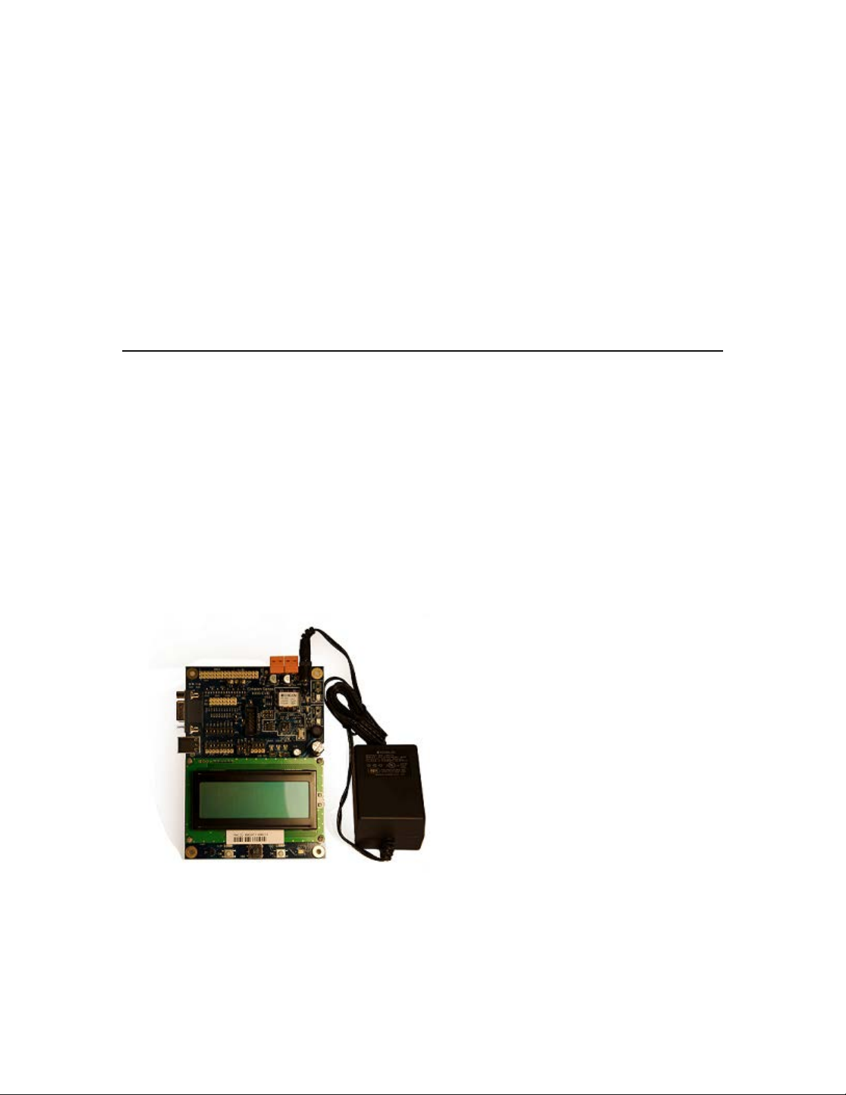
• Two FT 6000 EVB Evaluation Boards. The FT 6000 EVBs are evaluation boards that you
can use to run example applications and to prototype and debug your own applications. Each
includes an FT 6050 Smart Transceiver and can be attached to an IzoT or L
topology (FT) twisted pair channel.
• IzoT Commissioning Tool EVK Edition DVD. Contains the software tool for designing,
installing, and maintaining IzoT and L
includes the Microsoft Visio 2010 diagramming and vector graphics edition application.
• IzoT Network Services Server CD. Contains the network operating system that is the
standard network management software platform for commercial and industrial IzoT and
ONWORKS networks.
L
• IzoT Router. A ready-to-run application for connecting IzoT devices on an Ethernet channel
with IzoT and LonWorks devices on an FT channel. The router automatically forwards
packets between the Ethernet and FT channels.
ONWORKS control networks. The EVK Edition
ONWORKS free
• IzoT Plug-in for Wireshark. Wireshark is a free and open-source packet analyzer for IP
networks. It is used for net work troubles hooting and analysis. A plug-in for Wireshark is
included with the IzoT NodeBuilder software that enabled Wireshark to decode LonTalk/IP
packets.
• Quick Start Guide. This document describes how to install the software included with your
FT 6000 EVK; connect the FT 6000 EVBs and your development computer to an FT-10
channel; and create a simple network using the example application pre loaded on the FT
6000 EVB.
• FT 6050 Smart Transceiver sample chips.
• Accessories including power supplies and cables.
The following sections describe each of the components.
IzoT NodeBuilder Development Tool
The IzoT NodeBuilder Development Tool is an integrated development environment (IDE) for
developing and debugging applications for Series 6000, 5000, and 3100 chips. It is available as a free
download that requires a serial number to be installed. A serial number for the IzoT NodeBuilder
software is included on the back of the IzoT Commissioning Tool EVK Edition DVD case that is
included with the FT 6000 EVK.I It inc ludes Neuron C example applications that you can run on your
FT 6000 EVBs and use to further learn how to develop your own device applications.
The IzoT NodeBuilder software includes the following components:
• NodeBuilder Resource Editor. View standard types and functional profiles, and create
user-defined types and profiles if the standard resource files do not include the resources you need.
• NodeBuilder Code Wizard. Use a drag-and-drop interface to create your device’s interface and
then automa tically generate Neuron C source co d e that implements the device interface and
creates the framework for your device application.
6 Introduction
Page 21
• NodeBuilder Editor. Edit the Neuron C source code generated by the Code Wizard to create your
device’s application, or create and edit your own Neuron C code.
• NodeBuilder Debugger. Debug your application with a source-level view of your application code
as it executes.
• NodeBuilder Project Manager. Build and download your application image to your development
platform or to your own device hardware.
The IzoT NodeBuilder software include t hree Neuron C example applications that you c an run on your
FT 6000 EVBs. You can use these examples to test the I/O devices on the FT 6000 EVB, and create
simple IzoT and L
ONWORKS networks. You can view the Neuron C code used in the e xample
applications, and then create a new device application by mod ifying the existing example applic a tions
or by developing the device application from scratch.
For more information on using the FT 6000 EVB example applications, see the FT 6000 EVB
Examples Guide.
FT 6000 EVB Evaluation Boards
The IzoT FT 6000 EVK includes two FT 6000 EVBs. Each EVB is a complete Series 6000 IzoT and
ONWORKS device that you can use to evaluate the IzoT and LONWORKS platforms and create IzoT
L
ONWORKS devices. The FT 6000 EVB includes an FT 6050 Smart Transceiver with an external
and L
10 MHz crystal (you can adjust the system’s internal clock speed from 5MHz to 80MHz), an FT-X3
communication transformer, 512KB external serial flash memory devices, and a 3.3V power source.
The FT 6000 EVB features a compact design that includes the following I/O devices that y ou can use
to develop prototype and production devices and test the FT 6000 EVB example applications:
• 4 x 20 character LCD
• 4-way joystick with center push button
• 2 push-button inp uts
• 2 LED outputs
• Light-level sensor
• Temperature sensor
The FT 6000 EVB Eva luation Board also includes an EIA-232/TIA-232 (formerly RS-232) and USB
interfaces that you can use to connect the board to your development computer and perform
application-level d ebugging.
2
Each FT 6000 EVB also features a flash ICE header that supports the SPI and I
C interfaces for fast
downloads when programming the external non-volatile memory of the FT 6000 Smart Transceiver on
the board.
IzoT NodeBuilder User's Guide 7
Page 22

For more information on the FT 6000 EVB hardware, including detailed descriptions of its Neuron
core, I/O devices, service pin and reset buttons and LEDs, and jumper settings, see the FT 6000 EVB
Hardware Guide.
IzoT Commissioning Tool
The IzoT Commissioning Tool is a software tool that you can use to i nstall, connect, conf igure, test,
and update devices that you develop with the IzoT NodeBuilder software. It is a software package for
designing, installin g, and maint aining IzoT and L
IzoT Network Services Server, the Izot Commissioning Tool combines a powerful network services
platform with an easy-to-use Visio user interface. The I zoT Commissioning tool is compatible with a
number of OpenLNS and LNS plug-ins, simplifying net work installation and integration for devices
with plug-in support.
The IzoT Commissioning Tool can be used to manage all phases of a network’s life cycle, from the
initial design and commissioning to the ongoing operation, because it provides the functionality of
several network tools i n one single solution:
• Network Design Tool. You can design a network onsite or offsite (either connected to the network
over the Internet or not connected to it all), and then modify it anytime. The IzoT Commissioning
Tool can also learn an existing network’s design through a process called network recovery.
• Network Installation Tool. You can rapidly install a network designed offsite once it is brought
onsite. The device definitions can be quickly and easily associated with their corresponding
physical devices to reduce on-site commissioning time. The IzoT Browser provides complete
access to all network variables and configuration properties.
ONWORKS control networks. Based on Echelon’s
• Network Documentation Tool. You can create an IzoT CT drawing duri ng the network design a nd
installation process. This drawin g is an accurate, logical representatio n of the installed physical
network. The drawing is therefore an essential component of as-built reports.
• Network Operation Tool. You can operate the network using the operator interface pages
contained within the IzoT CT drawing.
• Network Maintenance Tool. You can easily add, test, remove, modify, or replace devices, routers,
channels, s ubsystems, and connections to maintain the network.
This guide describes many of the IzoT Commissioning Tool functions that you will use with the IzoT
NodeBuilder tool. See the IzoT Commissioning Tool User’s Guide for more information on the IzoT
Comnmissioning Tool and to learn how it can be used to install, operate, and maintain your operational
networks in addition to your development networks.
IzoT Network Services Server
The IzoT Network Service Server is a network operating system that i s the standa rd network
management software platform for commercial and industrial IzoT and L
ONWORKS networks.
IzoT Router
The IzoT Router is a ready-to-run application for connecting IzoT devices on an Ethernet channel with
IzoT and Lo nWorks devices on an FT channel. The router automatically forwards packets between the
Ethernet and FT channels.
IzoT Plug-in for Wireshark
Wireshark is a free and open-source packet analyzer for IP networks. It is used for network
troubleshooting and analysis. A plug-in for Wireshark is included with the IzoT NodeBuilde r software
that enabled Wireshark to decode LonTalk/IP packets. See the IzoT Plug-in for Wireshark Guide for
details on how to download Wire shark, install the IzoT plug-in for Wireshark, and use Wireshark with
LonTalk/IP networks.
8 Introduction
Page 23

Introduction to NodeBuilder Device Development and Network Integration
An IzoT or LONWORKS network consists of intelligent devices (such as sensors, actuators, and
controllers) that communicate with each other using a common protocol over one or more
communications channels. Network devices are sometimes called nodes.
Devices may be Neuron hosted or host-based. Neuron hosted devices run a compiled Neuron C
application on a Neuron Chip or Smart Transceiver. You can use the IzoT NodeBuilder tool to
develop, test, and debug Neuron C applications for Neuron hosted devices.
Host-based devices run applications on a processor other than a Neuron Chip or Smart Transceiver.
Host-based devices may run applications written in any language available to the processor. A
host-based device may use a Neuron Chip or Smart Transceiver as a communications processor, or it
may handle both application processing and communications processing on the host processor. The
IzoT NodeBuilder tool supports s ome of the common tasks occurring in the creation of host -based
devices; however, an additional host-based device development tool is required.
Each device includes one or more processors that implement the LonTalk/IP or the ISO/IEC
Control Network Protocol (CNP). Each device also includes a component called a transceiver to
provide its interface to the communications channel.
A device publishes and co nsumes information as instructed by the application that it is running. T he
applications on different devices are not synchronized, and it is p ossible that multiple devices may all
try to talk at the same time. Meaningful transfer of information between devices on a network,
therefore, requires organization in the form of a set of rules and procedures. These rules and
procedures are the communication protocol, which may be referred to simply as the protocol. The
protocol defines the format of the messages being transmitted between devices and defines the actions
expected when one device sends a message to another. The protocol normally takes the form of
embedded software or firmware code in each device on the network. The CNP
defined by the ISO/IEC 14908-1 standard (defined national ly in the Uni ted States , Europe, and China
by the ANSI/EIA 709.1, EN 14908, and GB/Z 20177 standards, respectively). LonTalk/IP is based on
the ISO/IEC 14908-1 standard, with extensions to use IP as the transport protocol.
is an open protocol
Channels
A channel is the physical media between devices upon which the devices communicate. The
LonTalk/IP and CNP protocols are media independent; therefore, numerous types of media can be
used for channels: twisted pair, power line, fiber optics, IP, and radio frequency (RF) to name a few.
Channels are categorized into channel types, and the channel types are characterized by the device
transceiver. Common channel types include TP /FT-10 (ISO/IEC 14908-2 twisted pair free topology
channel) which is also called FT, TP/XF-1250 (high-speed twisted pair channel), PL-20 (ISO/IEC
14908-3 power line channel), FO-20 (ANSI/CEA-709.4 fiber optics channel), and IP-852 (ISO/IEC
14908-4 IP-communication).
14908-1
Different transceivers may be able to interoperate on the same channel; therefore, each transceiver type
specifies the channel type or types that it supports. The choice of channel type affects transmission
speed and distance as well as the network topology.
The IzoT Node Builder tool, IzoT Commissioning Tool, and Neuron Chips support all standard channel
types, but not all Neuro n Chips support all transceiver and channel types. Smart Transceivers
combine the transceiver and Neuron core in the same chip, and therefore support the channel types
supported by the integrated transceiver.
Routers
Multiple channels can be connected using routers. Routers are used to manage network message
traffic, extend the physical size of a channel (both length and number of devices attached), and connect
IzoT NodeBuilder User's Guide 9
Page 24

channels that use different media (channel types) together. Unlike other devices, routers are always
attached to at least two channels.
The IzoT Router can be configured to act as a DHCP relay for address allocation on the LonTalk/IP
network. DHCP relay can be used to have a single server perform all of the allocation of addresses in
a network, and then have the server’s allocations forwarded onto another subnet.
To enable t he DHCP relay functionality, go to the DHCP page on configuration Web page of the IzoT
Router. Once there, select the Relay option and a box to enter the address of the DHCP server
appears. Enter the IP address of your server and click the Save Configuration button. DHCP requests
are now forwarded from the LonTalk/IP network to the DHCP server, and responses from the server
will be forwarded to devices on the LonTalk/IP network.
The DHCP server must have a separate subnet set up to allocate addresses from the LonTalk/IP subnet.
This is because the IzoT Router treats the IP and LonTalk/IP subnets as separate subnets, and uses the
subnets to determine which subnet to send me s s ages on. The subnet on the FT side needs to be
different than the subnet on the E t hernet side . If both the LonTalk/IP and IP subnets share the same
address range, the router cannot determine where to send the messages.
Applications
Every IzoT and LONWORKS device contains an application that defines the device’s behavior. The
application defines the inputs and outputs of the device. The inputs to a device can include
information sent on LonTalk/IP and L
from the device hardware (for example, the temperature from a temperature sensing device). The
outputs from a device can include information sent on LonTalk/IP and L
devices, as well as commands sent to the device hardware (for example, a fan, light, heater, or
actuator). You can use the IzoT NodeBuilder tool to write a device’s Neuron C ap plication.
ONWORKS channels fro m other devices, as well as information
ONWORKS channels to other
Program IDs
Every LONWORKS application has a unique, 16 digit, hexadecimal standard program ID with the
following format: FM:MM:MM:CC:CC:UU:TT:NN. This program ID is broken down into the
following fields:
Field Description
Format (F)
A 1 hex-d igit value d efining the structure o f the program ID. The up per
bit of the format defines the program ID as a standard program ID (SPID)
or a text program ID. The upper bit is set for standard program IDs, so
formats 8–15 (0x8–0xF) are reserved for standard program IDs.
• Program ID format 8 is reserved for L
ONMARK certified devices.
• Program ID format 9 is used for devices that will no t be L
certified, or for devices that will be c e rtified but are still in
development or have not yet completed the certification process.
• Program ID formats 10–15 (0xA–0xF) are reserved for future use.
• Text program ID formats are used by network interfaces and legacy
devices and, with the exception of network interfaces, cannot be used
for new devic es.
The IzoT NodeBuilder tool can be used to create applications with
program ID format 8 or 9.
ONMARK
Manufacturer ID (M)
A 5 hex-digit ID that is unique to each L
ONWORKS device manufacturer.
The upper bit identifies the manufacturer ID as a standard manufacturer
ID (upper bit clear) or a temporary manufacturer ID (upper bit set).
10 Introduction
Page 25

• Standard manufacturer IDs are assigned to manufacturers when they
A 2 hex-digit value identifying the specific pr oduct model. Model
Field Description
join LONMARK International, and are a lso published by LONMARK
International so that the device manufacturer of a L
device is easily identified. Standard manufacturer IDs are never
reused or reassigned. If your company is a L
you do not know your man ufacturer ID, you can find your I D in the
list of manufacturer IDs at
list at the time of release of the NodeBuilder tool is also included with
the IzoT NodeBuilder software.
• Temporary manufacturer IDs are available at no charge to anyone on
request by filling out a simple for m at www.lonmark.org/mid.
ONMARK certified
ONMARK member, but
www.lonmark.org/spid. The most curr ent
Device Class (C)
Usage (U)
Channel Type (T)
Model Number (N)
A 4 hex-d igit value identifying the primary function of the device. This
value is drawn from a registry of p re-defined device class definitions. If
an appropriate device class designation is not available, the L
ONMARK
International Secretary will assign one, upon request.
A 2 hex-d igit value identifying the intended usage o f the device. The
upper bit specifies whether the device has a changeable interface. The
next bit specifies whether the remainder of the usage field specifies a
standard usage or a functional-profile specific usage. The standard usage
values are drawn from a registry of pre-defined usage definitions. If an
appropri ate usage designation i s not available one will be assigned upon
request. If the second bit is set, a custom set of usage values is specified
by the primary functional profile for the device.
A 2 hex-digit value ide nt ifying the channel type suppo rted by the device’s
transceiver. The standard channel-type values are drawn from a registry
of pre-defined channel-type definitions. A custom channel-type is
available for channel types not listed in the standard registry.
numbers are assigned by the product manufacturer and must be unique
within the device class, usage, and channel type for the manufacturer. The
same hardware may be used for multiple model numbers depending on the
program that is loaded into the hardware. The model number within the
program ID does not have to conform to your published model number.
See the LonMark Application Layer Interoperability Guidelines for more
information about program IDs.
Network Variables
Applications exchange information with other LONWORKS devices using network variables. Every
network variable has a direction, type, and length. The network variable direction can be either input
or output, depending on whether the network variable is used to receive or send data. The network
variable type determines the format of the data.
Network variables of identical type and length but opposite directions can be connected to allow the
devices to share information. For example, an application on a lighting device could have an input
network variable that was of the switch type, while an application on a dimmer-switch device could
have an output networ k variable of the same t ype. A network management tool such as the IzoT
Commissioning Tool could be used to connect these two devices, allowing the switch to control the
lighting device, as shown in the following figure:
IzoT NodeBuilder User's Guide 11
Page 26
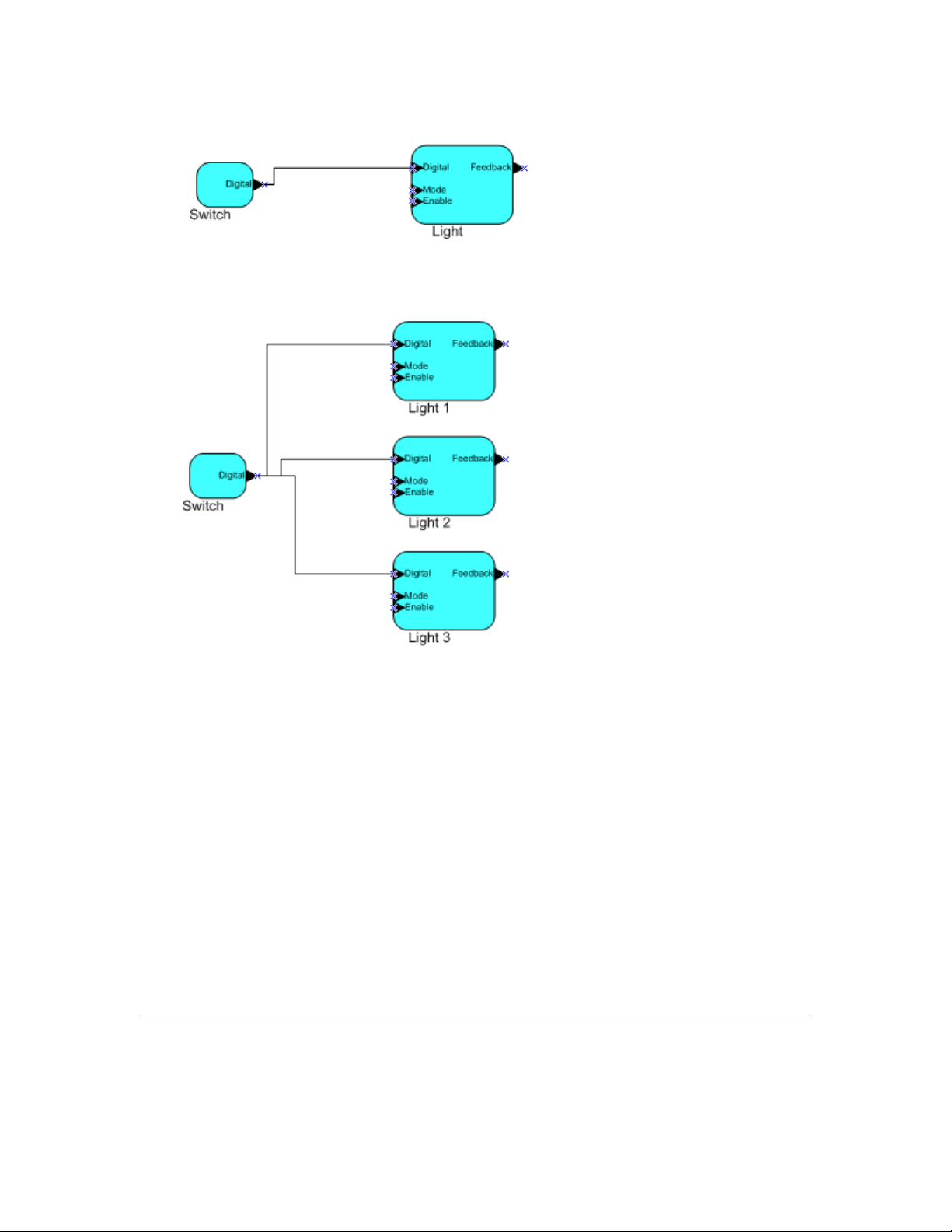
A single network variable may be connected to multiple network variables of the same type but
opposite direction. The following example shows the same switch being used to control three lights:
The application program in a device does not need to know where input network variable values come
from or where output network varia ble values go. When the application progra m has a changed value
for an output network vari able, it simply assig ns the new value to the output network variabl e.
Through a process called binding that takes place during network design and installation, the device is
configured to know the logical address of the other device or group of devices in the network
expecting that network variable’s values. The device’s embedded firmware assembles and sends the
appropriate message(s) to these destinations. Similarly, when the device receives an updated value for
an input network variable required by its application program, its firmware passes the data to the
application program. The binding process thus creates logical connections between an output network
variable in one device and an input network variable in another device or group of devices.
Connections may be thought of as virtual wires. For example, the dimmer-switch device in the
dimmer-switch-light example could be replac ed with an occupancy sens or, witho ut making any
changes to the lightin g device.
The NodeBuilder Code Wizard automatically generates the required network variable declarations for
your device’s interface in your device’s Neuron C application. Typically, you don’t need implement
any code in the device application to handle the binding process, or the source or destination devices
for network variable values. Neuron C provides an easy-to-use programming model familiar to any C
language programmer that enca psulates the complexity of distrib uted a pplications.
Configuration Properties
IZOT AND LONWORKS applications may also contain configuration properties. Configuration
properties allow the device’s behavior to be custo mi zed using a network management tool such as t he
12 Introduction
Page 27
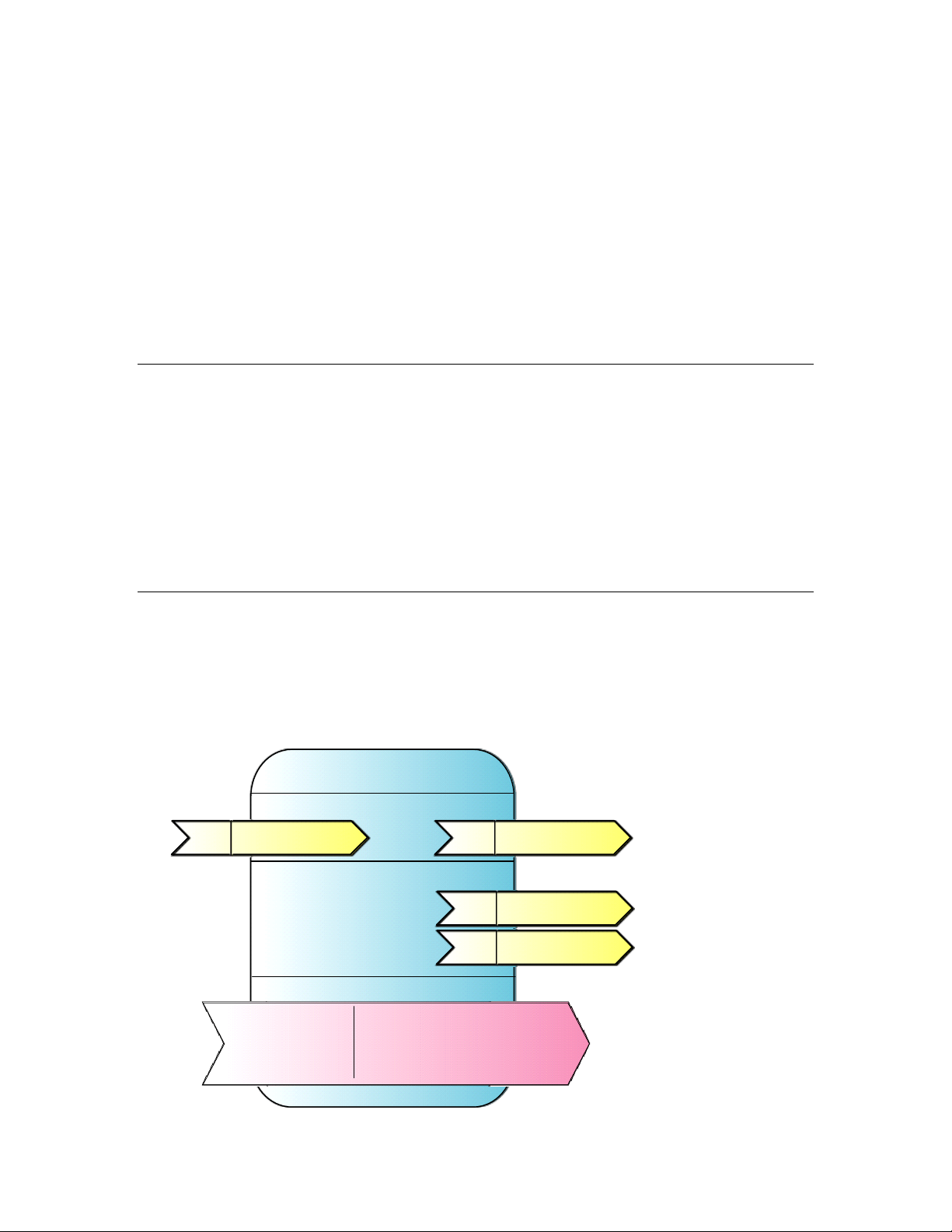
Lamp Actuator
Mandatory network variables
Configuration properties
Optional network variables
nviLampValue
SNVT_switch
nv1
SFPTLampActuator
nvoLampValueFb
SNVT_switch
nv2
nvoEnergyCnt
SNVT_elec_kwh
nv4
nvoRunHours
SNVT_elapsed_tm
nv3
Mandatory
Optional
SCPT_location
SCPTinFbDly
SCPT_def_output
SCPTrunHrInit
SCPTrunHrAlarm
SCPTenrgyCntInit
IzoT Commissioning Tool or a customized plug-in created for the device (see the OpenLNS Plug-in
Programmer’s Guide for more information on creating OpenLNS device plug-ins).
For example, an application may allow an arithmetic function (ad d, subtract, multiply, or divide) to be
performed on two values received from two network variables. The function to be performed could be
determined by a configuration property. Another example of a configuration property is a heartbeat
that determines how often a device transmits network variable updates over the network.
Like network variables, configuration properties have types that determine the type and format of the
data they contain.
The Node Builder Code Wizard automatically generates the required configuration property
declarations for your device’s interface and most of the required infrastructure code in your device’s
Neuron C application. The IzoT NodeBuilder tool supports configuration properties with an
easy-to-use progr amming mod el in Neuron C.
Functional Blocks
Applications in devices are divided into one or more functional blocks. A functional block is a
collection of network variables and configuration properties, which are used together to perform one
task. These network variables and configuration properties are called the functional block members.
For example, a digital input device could have four digital input functio nal b locks that contain the
configuration properties and output network variabl e members for each of t he four hardware d igital
inputs on the device.
The NodeBuilder Code Wizard automatically generates the required functional block declarations for
your device’s interface in your device’s Neuron C application.
A functional block is an implementatio n of a functional profile.
Functional Profiles
A functional profile defines mandatory and optional network variable and configuration property
members for a type of functional block. For example, the standard functional profile for a light
actuator has mandatory SNVT_switch input and output network varia bles, optional
SNVT_elapsed_tm and SNVT_elec_kwh output network variables, and a number of optional
configuration properties. The following diagram illustrates the components of the standard light
actuator functional profile:
IzoT NodeBuilder User's Guide 13
Page 28

When a functional block is created from a functional profile, the application designer can determine
which of the optional configuration properties and network variables to implement.
Hardware Templates
A hardware template is a file with a .NbHwt extension that defines the hardware configuration for a
device. It specifies hardware attributes that include the transceiver type, Neuron Chip or Smart
Transceiver model, clock speed, system image, and memory configuration. Several hardware
templates are included with the IzoT NodeBuilder tool. You can use these or create your own.
Third-party development platform suppliers may also include hardware templates for their platforms.
Neuron C
Neuron C is a programming language, based on ANSI C, used to develop applications for devices that
use a Neuron Chip or Smart Transceiver as the application processor. Neuron C includes extensions
for network communication, device configuration, hardware I/O, and event-driven scheduling.
Device Templates
A device template defines a device type. The IzoT NodeBuilder tool uses two types of device
templates. The first is a NodeBuilder device template. The NodeBuilder device template is a file with
a .NbDt extension that specifies the information required for the IzoT NodeBuilder tool to build the
application for a device. It contains a list of the application Neuron C source files, device-related
preferences, and the hardware template name. When the application is built, the IzoT NodeBuilder
tool automatically produces a n IzoT device template and passes it to the IzoT Commissioning Tool and
other netwo rk tools. The IzoT device template defines the device interface, and it is used by the IzoT
Commissioning Tool and other network tools to configure and bind the device.
Device Interface Files
A device interface file (also known as an XIF file or an ex te rnal interface file) is a file that specifies the
interface of a device. It includes a list of all the functional blocks , net wor k variables, configuration
properties, and configuration property default values defined by the device’s application. IzoT tools
such as the IzoT Commissioning Tool use device interface files to create an IzoT device template.
This enables the network tool to be used to create network designs without being connected to the
physical devices, and it speeds up some configuration steps when the network tool is connected to the
physical device. A text device interface file with a .XIF extension is required by the LonMark
Application Layer Interoperability Guidelines. A text device interface file is automatically produced
by the IzoT NodeBuilder tool when you build an application. The IzoT NodeBuilder tool als o
automatically creates binary (.XFB extension) a nd optimized-binary (.XFO extension) versions of the
device interface file that speed the import process for IzoT tools such as the IzoT Commissioning Tool.
Resource Files
Resource files define network variable types, configuration prop erty types, and functiona l profiles .
Resource files for standard types and profiles are distributed by L
resource files define standard network variable types (SNVTs), standard configuration property types
(SCPTs), and standard functional profiles. For example, SCPT_location is a standard configuration
property type for configuration properties containing the device loca t ion as a text string, and
SNVT_temp_f is a network variable type for network variables containing temperature as a
floating-point number. The standard network variable and configuration property types are defined at
types.lonmark.org.
As new SNVTs and SCPTs are defined, updated resource files and documentation are posted to the
ONMARK Web site. Standard functional profile s ar e inclu d ed with the IzoT NodeBuilder tool, and
L
their documentation is also availa ble on the L
resource files and documentation, go to the L
ONMARK Web site. To view and download the latest
ONMARK Web site at www.lonmark.org.
ONMARK International. The standard
14 Introduction
Page 29

Device manufacturers may also create user resource files that contain manufacturer -defined types and
profiles called user network variable types (UNVTs), user configuration property types (UCPTs), and
user functional profiles (UFPTs).
You can create applications that only use the standard types and profiles. In this case, you do not need
to create user-defined resource files. If you need to define any new user types or profiles, you will use
the NodeBuilder Resource Editor to create them.
Targets
A target is a LONWORKS devi ce whose application is built by the IzoT NodeBuilder tool. There are
two types of targets, development targets and release targets. Development targets are used during
development; release targets are used when development is complete and the device will be released to
production. Each NodeBuilder device template specifies the definition for a development target and a
release target. Both target definitions use the same source code, program ID, interface, and resource
files, but can use different hardware templates and compiler, linker, and exporter options. The source
code may include code that is conditionally compiled based on the type of target.
IzoT NodeBuilder User's Guide 15
Page 30

16 Introduction
Page 31

Installing the IzoT NodeBuilder
Development Tool
This chapter describes how to get started with your IzoT NodeBuilder tool, including
how to install the IzoT NodeBuilder software and connect the FT 6000 EVK
hardware.
2
IzoT NodeBuilder User's Guide 17
Page 32

Installing the IzoT FT 6000 EVK
To install your IzoT FT 6000 EVK, follow these steps:
1. Verify that you have a manufacturer ID. A manufacturer ID is required for many IzoT
NodeBuilder tool functions.
Standard manufacturer IDs are assigned to manufacturers when they join L
and are also published by L
certified device is easily identified. If your company is a L
know your manufacturer ID, you can go to www.lonmark.org/spid and find your ID in the list of
manufacturer IDs. The most current list at the time of release of the IzoT NodeBuilder tool is also
included with the IzoT NodeBuilder software.
If you do not have a manufacture r ID, you can instantly get a temporary manufacturer ID by filling
out a simple form at www.lonmark.org/mid.
2. Register your IzoT FT 6000 EVK. This entitles you to a free replacement software download or
serial number if you lose either one in the future. To register your IzoT FT 6000 EVK, go to
www.echelon.com/register, select the FT 6000 EVK product, enter the serial number from the
back of your OpenLNS Commissioning Tool DVD case, enter the other information requested by
the form, and then clic k Reg is t er No w.
3. Insert the IzoT Commissioning Tool EVK Edition DVD into your computer, install the IzoT
Commissioning Tool software, and then activate the IzoT Commissioning Tool as described in
Chapter 2 of the IzoT Commissioning Tool User’s Guide. The IzoT Commissioning Tool must be
installed on your computer in order to install the IzoT NodeBuilder software.
4. Install the IzoT NodeBuilder software as described in the next section.
5. Connect the FT 6000 EVK hardware as described in Connecting the FT 6000 EVB Hardware
chapter of the FT 6000 EVB Hardware Guide.
6. Complete the quick-start exercise in Chapter 3, IzoT NodeBuilder Quick-Start Exercise. In t he
quick-start exercise, you will develop a device with one sensor and one actuator. The sensor is a
simple sensor that monitors a push button on the FT 6000 EVB and toggles a network variable
output each time the button is pressed. The actuator drives the state of an LED on the FT 6000
EVB based on the state of a network variable input.
ONMARK International so that the device manufacturer of a LONMARK
ONMARK member, but you do not
ONMARK International,
This quick-start guides you through all the steps of creating a device with the IzoT NodeBuilder
tool, including creating the NodeBuilder project, the device template, the device interface, and the
Neuron C code that implements your device interface; implementing device functionality in the
Neuron C code; buildi ng and downloading the device appl ication; testing the device in an IzoT or
ONWORKS network; and debugging the device application.
L
7. Run the Neuron C example applications included with the IzoT NodeBuilder tool on your FT 6000
EVBs. The IzoT NodeBuilder tool includes three Neuron C example applications
(NcSimpleExample, NcSimpleIsiExample, and NcMultiSensorExample) that you can use to te s t the
I/O devices on the FT 6000 EVBs, and create simple managed and self-installed IzoT or
ONWORKS networks.
L
The NcMultiSensorExample application is pre-loaded on the FT 6000 EVBs and runs in
Interoperable Self-installation (ISI) mode by default. You install and connect this example
application and the other examples using the IzoT Commissioning Tool, or using the ISI protocol.
See the FT 6000 EVB Examples Guide for more information on using these exa mple applications.
Installing the IzoT NodeBuilder Software
To install the IzoT NodeBuilder software, follow these steps:
1. Download the IzoT NodeBuilder software from www.echelon.com/downloads.
18 Installing the IzoT NodeBuilder Development Kit
Page 33

2. Run the IzoT NodeBuilder installer .
3. Run the NodeBuilder430.exe self-extracting installation program. The Welcome window of the
NodeBuilder software installer opens.
4. Click Next. The NodeBuilder Development Tool License Agreement window opens.
5. Read the license agreement (see Appendix D, NodeBuilder Software License Agreement, for a
printed version of this license agreement). If you agree with the terms, click Accept the Terms
and then click Next. The Customer Information window appears.
IzoT NodeBuilder User's Guide 19
Page 34
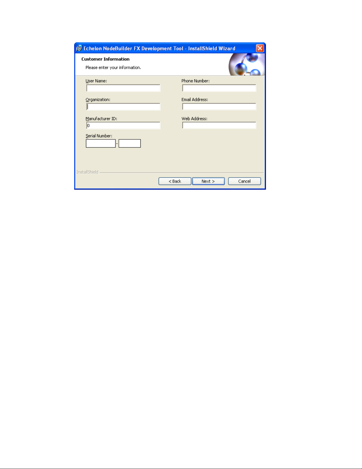
User Name
Your name. The name may be entered automatically based on the user
Organization
The name of your company. The name may be entered automatically
Manufacturer ID
If you have a s t andard manufacturer ID, enter it decimal format.
Phone Number
The phone number where you can be contacted.
Email Address
The e-mail address where you can be contacted.
Web Address
Your company’s Web site.
6. Enter the NodeBuilder serial number on the back of IzoT Commissioning Tool DVD case in the
Serial Number box. Optionally, you can enter the following registration information. T he IzoT
NodeBuilder tool automatically enters this information into your re so urc e files. Your phone
number, e-mail address, and Web address will be included with any resource file that you create
and distribute.
currently logged on and whether other Echelon products are insta lle d on
your computer.
based on the user currently logged on and whether other E chelon
products are installed on your computer.
If your company is a LONMARK member, but you do not know your
manufacturer ID, you can find your ID in the list of manufacturer IDs at
www.lonmark.org/spid. The most current list a t the time of release of
the IzoT NodeBuilder tool is also included with the IzoT NodeBuilder
software.
If you do not have a standard manufacturer ID, you can request a
temporary manufacturer ID by filling out a simple form at
www.lonmark.org/mid.
Note: You can enter or modify this infor mation after installing the IzoT NodeBuilder software in
the NodeBuilder Project Manager. To do this, create or open a NodeBuilder project, click
Project, click Settings (or right-click the Project folder in the Project pane and click Settings on
the shortcut menu), and then click the Registration tab in the NodeBuilder Project Properties
dialog.
20 Installing the IzoT NodeBuilder Development Kit
Page 35

7. Click Next. If your computer does not have a L
window appears. Choose a L
ONWORKS folde r in which you want the IzoT NodeBuilder software
ONWORKS directory, the Destination Location
installed. By default, the IzoT NodeBuilder software is installed in the C:\Program Files
(x86)\LonWorks folder if you have not previously installed any Echelon or L
ONMARK products
(this will not likely be the case because you should have already installed the IzoT Commissioning
Tool, which is installed in the C:\Program Files (x86)\LonWorks folder by default on 64-bit
versions of Windows). Click Next.
8. The Setup Type window opens.
9. Select the type of installation to be performed. Select Complete to install NodeBuilder feat ure s or
select Custom to choose whether to install the FT 6000 EVB examples, NodeBuilder LTM-10A
examples, both sets of examples, or neither on your computer. Click Next. The Ready to Install
window appears.
IzoT NodeBuilder User's Guide 21
Page 36

10. Click Install to b e gin the NodeBuilder software installat ion. Before installing the IzoT
NodeBuilder software, the following programs are automatically installed or upgraded on your
computer (if they are not already installed on your computer, or if they are installed, but have a
lower version): NodeBuilder Resource Editor 4.0, L
ONMARK Resource Files 14.00, LNS Plug-in
Framework 1.10, and ISI Developer’s Kit 3.02.
11. After the IzoT NodeBuilder software has been installed, a window appears stating that the
installation has been complete d successfully.
12. Click Finish. If a window appears prompting you to reboot your computer now or later, click Yes
to reboot your computer now.
22 Installing the IzoT NodeBuilder Development Kit
Page 37

13. Once the installation has co mple te d, you will be given the option to view the ReadMe file. See
the ReadMe file for updates to the NodeBuilder documentation.
14. If you do not have a PDF document viewer, install Adobe Reader from get.adobe.com/reader/.
IzoT NodeBuilder User's Guide 23
Page 38

Page 39

3
IzoT NodeBuilder Quick-Start Exercise
This chapter demonstrates how to create an IzoT or LONWORKS device using the IzoT
NodeBuilder Development tool.
IzoT NodeBuilder User's Guide 25
Page 40

IzoT NodeBuilder Quick-Start Exercise
The following quick-start exercise demonstrates how to create an IzoT or LONWORKS device with the
IzoT NodeBuilder tool. It introduces NodeBuilder features and provides some familiarity with t he
NodeBuilder interface.
The first step required to develop a device is to define the requirements for the d e vice . For this
quick-start exercise, you will develop a device with one sensor and one actuator. The sensor is a
simple sens or that monitors a push button and toggles a network variable output each time the button i s
pressed. The actuator drives the state of an LED based on the state of a network variable input.
To develop an IzoT or L
steps:
1. Create a NodeBuilder project.
2. Create a NodeBuilder device template.
3. Define the device interface and generate Neuron C source code that implements it.
4. Develop the device application by editing your Neuron C source code.
5. Compile, build, and download your application.
6. Test your device interface.
7. Debug your device’s application.
8. Connect and test your device in a network.
Additional steps in the device development process include creating an IzoT CT stencil, an IzoT device
plug-in, a human-machine interface (HMI), and an installation application for your device; and
applying for L
Device Development Steps section that follows this quick-start exercise.
After you complete this exercise, you can load and run the Neuron C example applications that are
included wit h the IzoT NodeBuilder tool. The IzoT NodeBuilder software includes three Neuron C
example applications that you can loa d into your FT 6000 EVBs, and one Neuron C example
application that you can load into an LTM-10A platform with Gizmo 4 I/O Board (included with the
NodeBuilder FX/PL Tool, and available separately). You can use these examples to test the I/O
devices on the FT 6000 EVB or Gizmo 4 I/O board, and create simple L
browse the Neuron C code used by these examples to further learn how to develop your own device
applications.
For more information on using the FT example applications, see the FT 6000 EVB Examples Guide.
For more information on using the PL exa mple a pplication, see the NodeBuilder FX/PL Examples
Guide.
ONMARK certification for your device. These steps are summarized in the Additional
ONWORKS device with the IzoT NodeBuilder tool, perform the following
ONWORKS networks. You can
Step 1: Creating an IzoT NodeBuilder Project
A NodeBuilder project collects all the information about a set of devices that you are developing. You
will create, manage, and use NodeBuilder projects from the NodeBuilder Project Manager. The
project ma nager provides an integrated view of your entire project and provid es the tools you will use
to define and build your project.
To create an IzoT NodeBuilder project, start the NodeBuilder Project Manager from the IzoT
Commissioning Tool (CT) or directl y from the NodeBuilder program folder. You will typically start
the project manager from the IzoT CT because it simplifies the association of an Izo TNodeBuilder
project with an IzoT CT net work.
You can use the same NodeBuilder proj e c t with multiple IzoT CT networks, and you can us e a IzoT
CT network with multiple NodeBuilder projects. Ho wever, a n IzoT CT network can only be used wit h
one NodeBuilder project at a time.
To create a NodeBuilder project by starting the NodeBuilder Project Manager from the IzoT CT,
follow these steps:
26 IzoT NodeBuilder Quick-Start Exercise
Page 41

1. Create a new IzoT CT network. To do this, follow these steps:
a. Click Start on the taskbar, point to Programs, point to Echelon OpenLNS CT, and then
select OpenLNS Commissio ni ng Tool. The LonMaker Design Manager opens.
b. In the Networ k Name property under New Network, enter IzoT NB Exercise.
c. Clea r the Show All Options check box und er New Network if it is selected.
d. Click Create Network to create the new network.
• A message may appear informing you that Visio must be launched and initialized so that
it can work with IzoT CT. Click OK.
• A warning may appear asking you if you want to enable macros. You must enable
macros for the IzoT CT to function.
e. Visio 2010 starts and the Naming page in the Network Wizard appears. Click Next. The
Network Interface page appears.
IzoT NodeBuilder User's Guide 27
Page 42

f. Select the Network Attached check box and then sel ect the LonTalk/IP network interface
you created when you installed your FT 6000 EVK.
g. Click Next. The Management Mode page appears.
h. Select OnNet. This means that changes to the IzoT CT drawing are sent immediately to your
NodeBuilder devices on the network. Click Finish.
i. IzoT CT creates and opens a new network drawing.
For more information on creating and op ening IzoT CT networks, see Chapter 3 of the IzoT
Commissioning Tool User’s Guide.
2. Click Add-Ins, click Open LNS CT, and then c lick NodeBuilder.
3. The New Project wizard opens.
4. Accept the default Create a New NodeBuilder Project option, and then click Next.
28 IzoT NodeBuilder Quick-Start Exercise
Page 43
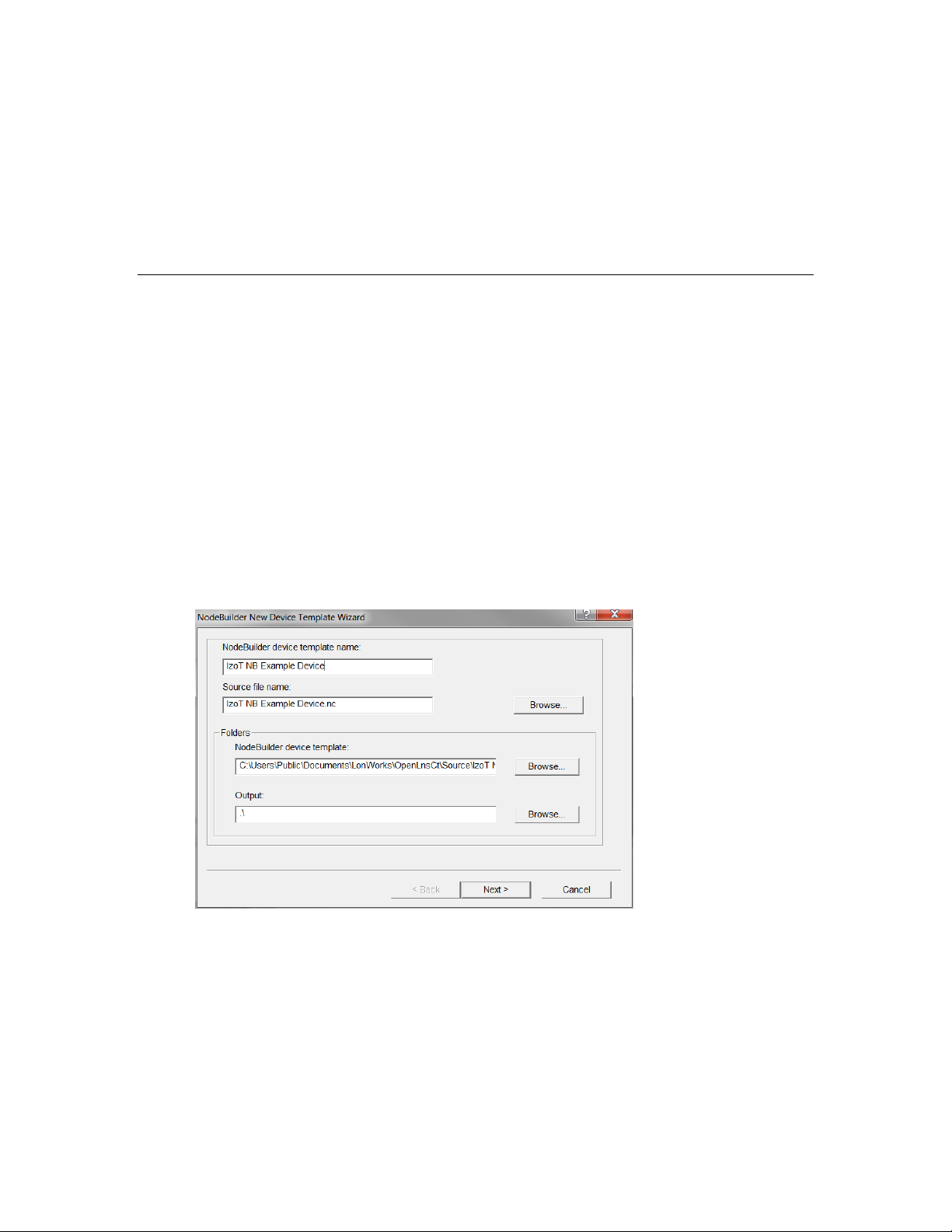
5. Accept the default NodeBuilder Project Name, which is the same name as the IzoT CT network,
and then click Next.
6. Accept the defaults in the Specify Default Project Settings dialog, and then click Finish.
7. The NodeBuilder New Device Template wizard starts. Proceed to the next section to create a
NodeBuilder device template.
For more information on creating NodeBuilder projects, see Chapter 4, Creating and Opening
NodeBuilder Projects.
Step 2: Creating a NodeBuilder Device Template
Each type of device that you develop with the IzoT NodeBuilder tool is defined by a pair of device
templates: a NodeBuilder device template and an IzoT device template. The NodeBuilder device
template specifies the information required for the NodeBuilder tool to build the application for a
device such as a list of the source code files and up to two hardware platforms for the device. The
IzoT device template define s the network interface to the device, and is used by IzoT tools such as the
IzoT Commi s s i oning Tool to configure and bind the device.
Each pair of device templates is identified by a unique program ID. Every device on a network with
the same program ID mus t have the same device interface.
This section demonstrates how to create a NodeBuilder device template. The IzoT device template
will be created automatically when you build the application. To create the NodeBuilder device
template, follow these steps:
1. In the NodeBuilder Device Template Name p r o p er ty in the New Device Template wizard, enter
IzoT NB Example Device.
2. Click Next. The Program ID window appears.
IzoT NodeBuilder User's Guide 29
Page 44
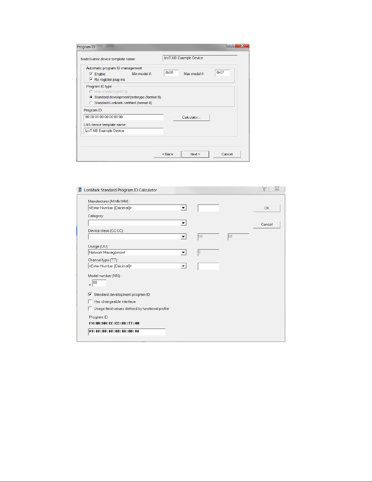
3. Click Calculator. The Standard Program ID Calculator dialog opens.
4. Enter the following values for the p r ogram ID fields:
• In the Manufacturer ID (M:MM:MM) property, enter your standard manufacturer ID or
temporary manufacturer ID in decimal format, or select the Examples manufacturer ID. By
default, the manufacturer ID that you entered during of the IzoT NodeBuilder tool installation
is shown by default.
If your company is a L
ONMARK member, but you do not know your manufacturer ID, you can
find your ID in the list o f manufactur er IDs at www.lonmark.org/spid.
If you do not have a standard manufacturer ID, you can request a temporary manufacturer ID
by filling out a simple form at www.lonmark.org/mid.
• In the Category property, select the I/O option.
30 IzoT NodeBuilder Quick-Start Exercise
Page 45

• In the Device Class (CC:CC) property, select the Multi-I/O module (5.01) option.
• In the Usage (UU) property, select the General option.
• In the Channel Type (TT) p r o p er ty, select the TP/FT-10 option.
• In the Model Number (NN) property, enter 01.
Note: The current list of manufacturer IDs, device classes, usage values, and channel types
are defined in an XML file (spidData.xml) that is available at www.lonmark.org/spid. This
file is updated as L
ONMARK International adds new manufacturer IDs, device classes, usage
values, and channel types.
5. Click OK to return to the New Device Template wizard. The Program ID property contains the
program ID you specified in the Standard Program ID Calculator dialog.
Tip: Do not clear the Enable check box under Automatic Program ID Management. This
enables the Model Number (NN) field in the program ID to be incremented a utomatically when
the external interface of the device is changed. This allows for the easy development of a device
with a changing network interfac e during development. The program ID will c ycle throug h the
range of specified model numbers to avoid two devices having the same program ID but different
external interfaces.
6. Click Next. The Hardware Template window opens.
7. Specify the development build and release build hardware template.
• If you are using the FT 6000 EVK hardware (FT 6000 EVBs), select FT 6000 EVB in both
the Development Build Hardware Template and Release Build Hardware Template
properties.
IzoT NodeBuilder User's Guide 31
Page 46

• If you are using the NodeBuilder FX/PL hardware (LTM-10A Platform with Gizmo 4 I /O
Board), select LTM-10A RAM in the Development Build Hardw are Template property,
and then select LTM-10A Flash in the Release Build Hardware Template property.
8. Click Finish. The N odeBuilder Code Wizard starts. There will be an initial pause as it reads the
available resource files. Proceed to the next section to generate Neuron C code that defines your
device’s interface.
32 IzoT NodeBuilder Quick-Start Exercise
Page 47

Step 3: Defining the Device Interface and Creating its Neuron C Application Framework
You can develop device applications with the IzoT NodeBuilder tool using the Neuron C programming
language. N euron C is based on ANSI C, with extensions for network communication, hardware I/O,
timing, and event handling.
The IzoT NodeBuilder tool includes a NodeBuilder Code Wizard, which automatically generates
Neuron C source code that defines the device interface (XIF). The device interface includes all the
functional blocks, network variables, and configuration properties implemented by your device. The
NodeBuilder Code Wizard also generates much of the code for the Node Object functional block,
which is a standard functional block that is used for maintaining and managing the de vi ce and its
functional blocks.
The left pane of the NodeBuilder Code Wizard is the Resource pane, which is used to display the
resources that are available for your application. The right pane is the Program Interface pane, which
is used to display and modify your device’s interface. You will define your device’s interface by
dragging f unctional profile templates and network var iable and configuration property types from the
Resource pane to the Program Interface pane.
After you run the NodeBuilder Code Wizard, you work with the generated code to implement your
device’s functionality. You can rerun the NodeBuilder Code Wizard at any time to modify your
device’s interface, while maintaining any changes that you have implemented in the source code.
In this step, you will automatically create Neuron C source code for a device with the following
functional blocks:
• An open-loop sensor functional block with a SNVT_switch output network variabl e.
• An open-loop actuator with a SNVT_switch inp ut ne t wo rk va ri ab le .
IzoT NodeBuilder User's Guide 33
Page 48

• A simple Node Object with no configuration properties (the NodeBuilder Code Wizard
automatically creates this func tional block).
To define your device interface and automatically create Neuron C source code for it using the Code
Wizard, follow these steps:
1. Create an open-loop sensor functional block with a SNVT_switch network variable. To do this,
follow these steps:
a. Expand the STANDARD (Scope 0: Standard) resource file under the LonWorks/Types
folder, and then expand the Functional Profile Templates folder to display the standard
functional profile templates (SFPTs).
b. Drag the SFPTopenLoopSensor (1) functional profile template from the Resource Pane on
the left side to the Functional Blocks folder in the Program Interface pane on the right side.
An openLoopSensor functional block appears under the Functional Blocks folder.
34 IzoT NodeBuilder Quick-Start Exercise
Page 49

c. Rename the openLoopSensor functional block to “Switch”. To do this, right-click the
openLoopSensor functional block in the Program Int erface pane, click Rename on the
shortcut menu, enter Switch, and then press ENTER or TAB. A warning message appears
warning that new source files will be generated as a result of the name change. Click OK.
d. Expand the Switch functional block, and then expand the Mandatory NVs folder to display
the nvoSwitch network variable.
IzoT NodeBuilder User's Guide 35
Page 50

e. Double-click the nvoValue network variable, or right-click it and then select Properties on
the shortcut menu. The NV Pro perties dialog opens.
f. In the Name property, change the network variable name to nvoSwitch.
g. In the NV Type proper ty, selec t SNVT_switch, and then click OK.
36 IzoT NodeBuilder Quick-Start Exercise
Page 51

2. Create an open-loop actuator with a SNVT_switch network variable.
a. Drag a SFPTopenLoopActuator functional profile template from the Resource Pane on the
left side to the Functional Blocks folder in the Program Interface pane on the right side.
b. Rename the openLoopActuator functional block to “LED”. A warning message appears
warning that new source files will be generated as a result of the name change. Click OK.
c. Expand the LED functio nal block, and then expand the Mandatory NVs folder to display the
nviValue network variable.
d. Double-click the nviValue network variable, or right-click it and then sele c t Properties on
the shortcut menu. The NV Pro perties dialog opens.
e. In the Name property, change the network variable name to nviLamp.
f. In the NV type property, select SNVT_switch, and the n click OK.
You have completed designing the external interface of the device. You will now use the
NodeBuilder Code Wizard to generate the source files for you.
3. Click the Generate and Close button in t he top-right corner of the NodeBuilder Code Wizard to
generate the Neuron C so urce files that implement your specified external interface.
4. The NodeBuilder Code Wizard closes and you are returned to the Project Manager window. The
Project pane within the project manager displays the files and templates defined for your project.
IzoT NodeBuilder User's Guide 37
Page 52

5. Double-click the IzoT NB E x ample Device.nc file in the Project pane to open the main Neuron C
file for this new device template.
6. Open the Switch.h and LED.h header files and view the functional block and configuration
property declarations.
7. Open the Switch.nc and LED.nc Neuron C files and view the default implementation of the
director function (named SwitchDirector or equivalent).
The director function is a mechanism that allows the developer to easily dispatch events to all the
functional blocks in a device with a single function call. For instance, during reset, the when
(reset) clause can dispatch the reset event for each functional block in the device when it is done
initializing the “glob al” components in the device. T hi s is done usi ng the following line of code:
executeOnEachFblock (FBC_WHEN_RESET);
8. Proceed t o the next sect ion to implement your device’s functionality by editing your Neuron C
code.
For more information on defining device interfaces and generating Neuron C code for them, see
Chapter 6, Defining Device Interfaces and Creating their Neuron C Application Framework.
Step 4: Developing the Device Appl ica tion
The Neuron C source code generated by the NodeBuilder Code Wizard implements your device’s
interface. The Code Wizard also generates a skeleton application framework, including the most
common tasks performed by the Node Object. When developing the device application, you will
typically concentrate on writing the algorithms that implement your device’s functionality. To do this,
you will edit the code generated by the Code Wizard and program any required interaction between the
device application and the I/O devices on your device hardware.
In this step, you will ad d Neuron C I /O declarations to the Switch.h, and LED.h header files, and then
implement your desired I/O functionality i n the Switch.nc and LED.nc Neur o n C f ile s.
Note: The I/O object declarations used for the FT 6000 EVK hardware (FT 6000 EVBs ) an d the
NodeBuilder FX/PL hardware (LTM-10A Platform with Gizmo 4 I/O Board) are different. Therefore,
38 IzoT NodeBuilder Quick-Start Exercise
Page 53

follow the section corresponding with the development platform or platforms you are using for the
appropriate code to use.
FT 6000 Evaluation Boards
1. Declare the I/O hardware for the Switch following these steps:
a. Double-click the Switch.h file in the Project pane to edit the source file.
b. Find the following line of code near the end of the Editor window:
//}}NodeBuilder Code Wizard End
c. Add the following line of code after the line referenced in step b.
IO_9 input bit ioSwitch1;
2. Add functionality to the Switch I/O following these steps:
a. Double-click the Switch.nc file in the Project pane.
b. Find the following line of code at the end of the Editor window:
#endif // _Switch_NC_
c. Add the following when-clause before the line referenced in step b:
when (io_changes (ioSwitch1))
{
nvoSwitch.state = !input_value;
nvoSwitch.value = input_value ? 200u : 0;
}
3. Declare the I/O hardware for the LED. To do this follow these steps:
a. Double-click the LED.h file in the Project pane.
b. Find the following line of code near the end of the Editor window:
//}}NodeBuilder Code Wizard End
c. Add the following line of code after the line referenced in step b.
IO_2 output bit ioLamp = 1;
4. Add functionality to the LED I/O following these steps:
a. Double-click the LED.nc file in the Project pane.
b. Find the following lines of code ne ar the beginning of the Editor window:
when(nv_update_occurs(nviLamp))
//
//}}NodeBuilder Code Wizard End
{
c. Add the following line of code after the lines referenced in step b:
io_out(ioLamp, !(nviLamp.value && nviLamp.state));
5. Click File and the n click Save All to save all your changes to the source files.
6. Proceed to the next section to compile your Neuron C application, and then build an applicatio n
image and download it to your device.
For more information on editing Neuron C code to implement your device’s functionality, see Chapter
7, Developing Device Applications.
IzoT NodeBuilder User's Guide 39
Page 54

Page 55

LTM-10A Platform and Gizmo 4 I/O Board
1. Declare the I/O hardware for the Switch following these steps:
a. Double-click the Switch.h file in the Project pane to edit the source file.
b. Find the following line of code near the end of the Editor window:
//}}NodeBuilder Code Wizard End
c. Add the following line of code after the line referenced in step b.
IO_6 input bit ioSwitch1;
2. Add functionality to the Switch I/O following these steps:
a. Double-click the Switch.nc file in the Project pane.
b. Find the following line of code at the end of the Editor window:
#endif // _Switch_NC_
c. Add the following when clause before the line referenced in step b:
when(io_changes(ioSwitch1))
{
nvoSwitch.state = !input_value;
nvoSwitch.value = input_value ? 200u : 0;
}
3. Declare the I/O hardware for the LED. To do this follow these steps:
a. Double-click the LED.h file in the Project pane.
b. Find the following line of code near the end of the Editor window:
//}}NodeBuilder Code Wizard End
c. Add the following line of code after the line referenced in step b.
IO_0 output bit ioLamp = 1;
4. Add functionality to the LED I/O following these steps:
a. Double-click the LED.nc file in the Project pane.
b. Find the following lines of code ne ar the beginning of the Editor window:
when(nv_update_occurs(nviValue))
//
//}}NodeBuilder Code Wizard End
{
c. Add the following line of code after the lines referenced in step b:
io_out(ioLamp, !(nviLamp.value && nviLamp.state));
5. Click File and the n click Save All to save all your changes to the source files.
6. Proceed to the next section to compile your N euron C application, and the n build an application
image and download it to your device.
For more information on editing Neuron C code to implement your device’s functionality, see Chapter
7, Developing Device Applications.
IzoT NodeBuilder FX User's Guide 41
Page 56

Step 5: Compiling, Building, and Downloading the Application
The IzoT NodeBuilder tool includes a complete set of tools for compiling your Neuron C application,
building an application image that can be loaded into your device, and downloading your application
image to your device.
When you buil d your application, t he IzoT NodeBuilder too l will create downloadable application
image files and device interface files. The downloadable application image file is used by the IzoT
Commissioning Tool and other network tools to download the compiled application image to a device.
The device interface file describes the external interface for your device. It is used by network tools
such as the I zoT Commis s ioning Tool to determine how to bind and configure your device. The
device interface file is also used by the IzoT NodeBuilder tool to automatically create the LNS device
template.
The IzoT NodeBuilder tool can create two device sets for each device that you build, one for a
development version of your device and one for a release, or production, version of your device. The
default project directory for your IzoT NB Exercise project is
C:\Users\Public\Documents\LonWorks\OpenLnsCt\Source\IzoT NB Exercise. The two device
file sets are written to different directories—the IzoT NB Example Device\Development directory
and the IzoT NB Exa mple D evice\Release directory. The development and release file set are both
stored within your project directory.
To compile, build, and download your application, follow these steps:
1. Right-click the IzoT NB Example Device device template icon in the Proje ct pane, then click
Build on the shortc ut men u.
2. If you receive any build errors, double-check that the code you entered matches that listed in Step
4: Developing Device Applications (you may receive some warnings, which c an be ignored in the
context of this quick-start exercise).
3. Click the Echelon IzoT CT/Visio button in the Taskbar to switch to the IzoT Commissioning Tool
(CT). You wil l use IzoT CT to install, bind, configure, and test the devices in your project. IzoT
42 Creating and Opening IzoT NodeBu il der Pr ojec ts
Page 57

CT displa ys a network dr awing that shows the devices, functional blocks, and connections in your
network.
IzoT CTl also displays stencils that contain shapes that you can drag to your IzoT CT drawing.
IzoT CT includes a NodeBuil de r Basic Shapes 4.00 stencil with shapes that you will use to add
new device s , functional blocks, and connect ions to your network drawing. The NodeBuilder
Basic Shapes 4.00 stencil contains shapes that can be used with any device. You can also create
custom stencils with shapes customized for your devices and networks.
The NodeBuilder Basic Shapes 4.00 stencil co ntains two shapes that you will use to d e fi ne your
devices during development. They are the Development Target Device shape and the Release
Target Device shape. These special device types help distinguish between other devices on the
network and the target d evices used by the IzoT NodeBuilder tool. The IzoT NodeBuilder tool
allows you to create a mixed network of development hardware (FT 6000 EVB or LTM-10A
Platforms), release hardware (your own hardware), and other devices.
4. Drag a Development Target Device shape from the NodeBuilder Basic Shapes 4 .00 stencil to
your network drawing. You can drop the shape anywhere, but a good location is just below the
Channel 1 sha pe on your drawing.
5. The New Device Wizard opens. In the Device Name property, enter NB Device, and then select
the Commission Device check b ox. Verify that IzoT NB Example Device is selected in the
NodeBuilder Device Template box.
IzoT NodeBuilder FX User's Guide 43
Page 58

6. Click Next three times. The window in the New Device Wizard lets you select the application
image to be downloaded to your device.
7. Select the Load Application Image check box and the n click Next. This specifies that you will
download to the device the binary application image file (.APB extension) that was automatically
created when you built the device with the IzoT No deBuilder tool. The application image files for
your NodeBuilder development devices are stored in the
C:\Users\Public\Documents\LonWorks\OpenLnsCt\Source\<NodeBuilder
Project>\<NodeBuilder Device Template>\Development folder.
44 Creating and Opening IzoT NodeBu il der Pr ojec ts
Page 59

8. The next window lets you set the initial device state and the source of configuration property values
when your device is commissioned.
9. Select the Online option under State. This means that yo ur device will run its application after it
has been commissioned.
10. Click Finish. The Press Service Pin window appears.
IzoT NodeBuilder FX User's Guide 45
Page 60

11. Press the service pin on the development platform to be loaded and commissioned. IzoT CT loads
the application image for your IzoT NB Example Device ap plication to the development platform
and makes it operational. When IzoT CT is done commissioning, it will return to the IzoT CT
drawing. The device shape will be will be solid green indicating that the device has been
commissioned and is online. The device application will not do anything until you test the device
or connect it to other devices.
12. Proceed to the next section to test your device’s interface using the IzoT Browser.
For more information on building and downloading device applications, see Chapter 8, Building and
Downloading Device Applications.
Step 6: Testing the Device Interface
The IzoT NodeBuilder tool makes it easy to test your device by itself, as well as to integrate your
device into a network and test its intera c tion with other devices.
The first tool that you will typically use for testing is the IzoT Browser. The browser displays all the
input and output network variables and configuration properties for your device. You will typically
exercise the hardware or network variable inputs to your device and observe the hardware and network
outputs from your device.
46 Creating and Opening IzoT NodeBu il der Pr ojec ts
Page 61

To test your device’s interface with the IzoT Browser, follow these steps:
1. Right-click the IzoT NB Example Device device in your IzoT CT drawing, then click Browse on
the shortcut menu.
2. The IzoT Browser opens. It displays the three functional blocks in your device interface (LED,
NodeObject, and Switch) and the network variables and configuration properties within each
functional block. You can only wr ite values to the input network variables (b l ue) and writable
configuration properties (green).
3. Click the Monitor All button (
IzoT NodeBuilder FX User's Guide 47
) on the toolbar to start polling all values.
Page 62
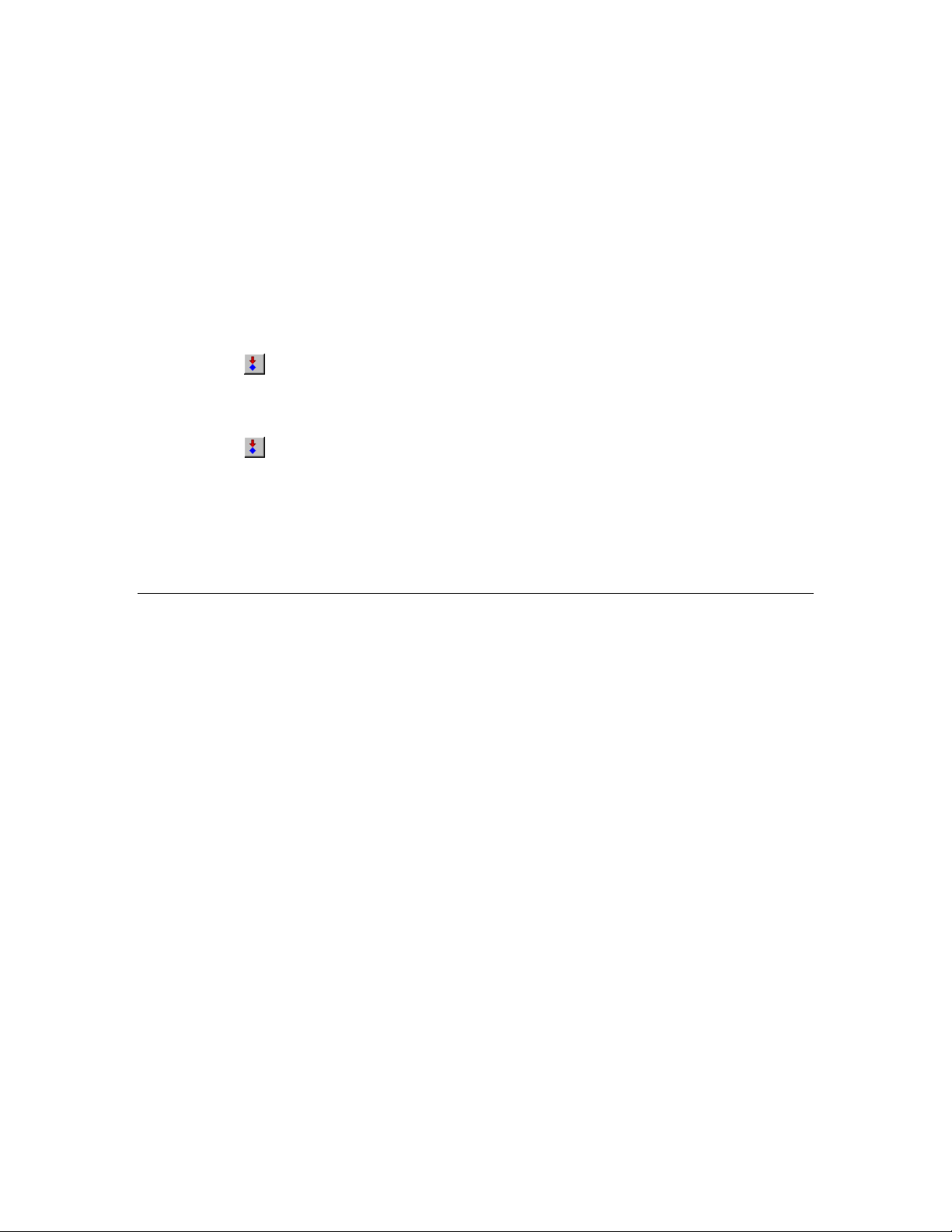
4. Press and hold the left button at the bottom of your development board (SW1 on the FT 6000
EVB; IO_6 on the Gizmo 4 I/O Board). The value of the nvoSwitch network va ri ab le in the
Switch functional block changes to 100.0 1, which means that the switch is at its maximum level
(100%) and on.
5. Release the left button at the bottom of your development board. The value of the nvoSwitch
network variable in the Switch functional block changes back to 0.0 0, which means that the
switch is at its lowest level (0%) and off.
Note: The nvoSwitch network variable does not toggle each time you press the button. Instead, it
depicts the current state of the button. You will modif y the behavio r of the Switch functional
block in Step 7: Debugging Your Device’s Application so that it acts as a toggle-switch.
6. Click anywhere in the row for the nviLamp network variable in the LED f unctional bl ock. In the
Value box in the browser toolbar, enter 100.0 1 and then press ENTER or click the Set Value
button (
(LED1 on the FT 5000 EVB; IO_0 on the Gizmo 4 I/O Board) to its maximum level (100%) and
turns it on.
7. In the Value box in the browser toolbar, enter 0.0 0, and then press ENTER or click the Set Value
button (
The LED functional block appears to be functioning correctly.
8. Proceed to the next section to debug your device’s application. You will modify your device
application so that the value of the nvoSwitch network variable in the Switch functional block
toggles each time the button is pressed instead of when the button is pressed and released.
) in the browser toolbar. This sets the LED on the left side of your development board
) in the browser toolbar. This returns the LED to its lowest level (0%) and turns it off.
For more information on testing your device, see Chapter 9, Testing a NodeBuilder Device Using the
IzoT Commissioning Tool.
Step 7: Debugging the Device Application
If your device does not function as expected, you can use the NodeBuilder Debugger to control and
observe the behavior of the device application. The debugger allows you to set breakpoints, monitor
variables, halt the application, step through the application, view the call stack, and peek and poke
memory. You can make changes to the code as you debug your device.
To debug your device’s a pplicati on with the NodeBuilder Deb ugger, follow these steps:
1. Click the Echelon IzoT/Visio button in the Taskbar to switch to the IzoT Commissioning Tool.
2. Right-click the NB Device device shape in your IzoT CT drawing, point to NodeBuilder, and then
click Debug on the shortcut m enu.
48 Creating and Opening IzoT NodeBu il der Pr ojec ts
Page 63

3. The NodeBuilder Project Manager appears, and a debug session for the device starts. There is a
short pause as the debug session is started while the IzoT NodeBuilder tool establishes
communication with the device’s debug kernel.
4. Double-click the Switch.nc file in the Project pane. A Debug window appears for the Switch.nc
file.
5. Find the when(io_changes(ioSwitch)) clause near the end of the file. This is the code
you added in Step 4: Developing the Device Application.
IzoT NodeBuilder FX User's Guide 49
Page 64
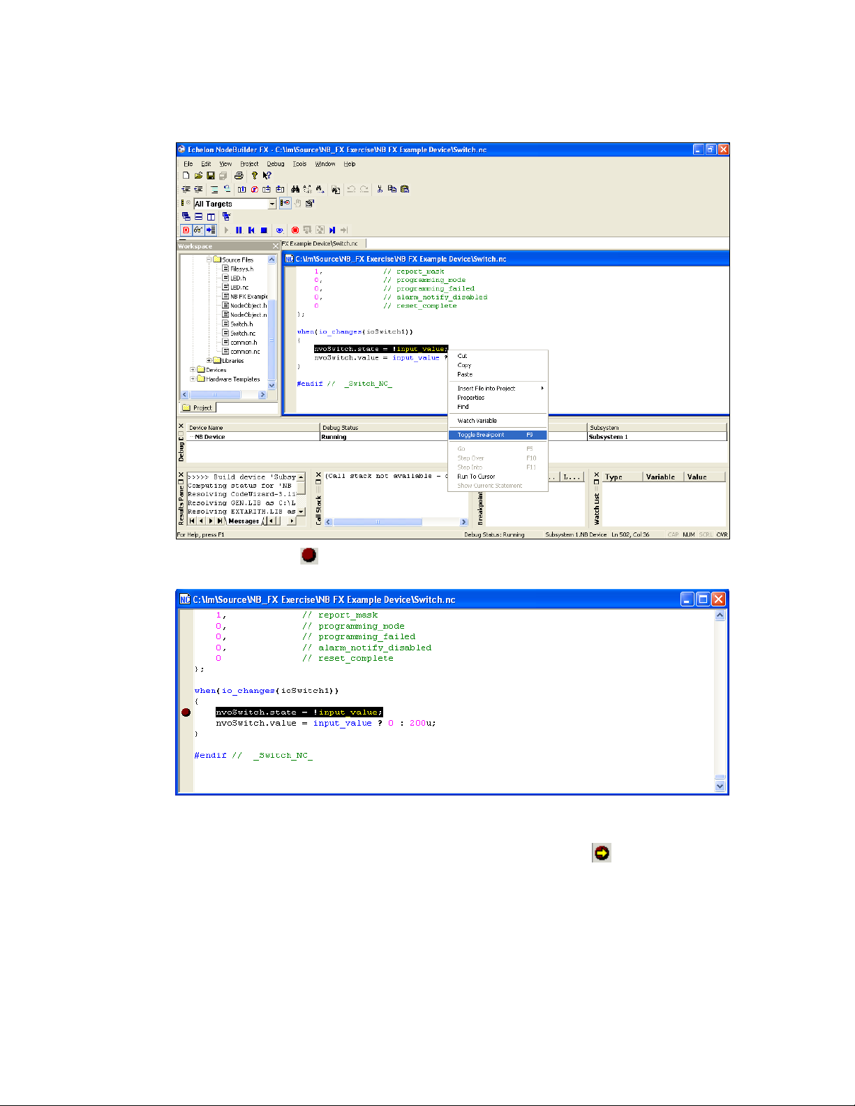
6. Right-click the nvoSwitch.state = !input_value line , and then cli ck Toggle
Breakpoint on the shortcut menu, or click anywhere in the line and press F9.
7. A breakpoint marker ( ) ap pears next to the line, and the line is added to the Breakpoint List
pane at the bottom of the NodeBuilder Project Manager.
8. Press and then release the left button at the bottom of your develop ment board (SW1 on the F T
6000 EVB; IO_6 on the Gizmo 4 I/O Board). Observe that program execution stops at your
breakpoint as denoted by the arrow symbol on top the breakpoint symbol (
).
50 Creating and Opening IzoT NodeBu il der Pr ojec ts
Page 65

9. Right-click the input_value variable in the line of code in which you set the breakpoint, and
then click Watch Variable on the shortc ut menu.
10. The Watch Variable dialog opens.
IzoT NodeBuilder FX User's Guide 51
Page 66

11. Click Add Watch. The variable is added to the Watch List pane at the bottom of the NodeBuilder
Project Manager. This pane displays each of the variables added to the watch list and their current
values.
12. Click the Step Into butto n (
you reach the end of the when clause. The input_value variable is 0.
13. Click the Step Into button to observe that the function executes a second time. The
input_value variable is now 1.
14. Click the Resume butt on (
execution.
15. Click Debug, point to Stop Debugging, and then select All Devices.
) in the debug toolbar to step through the code in the f unction unt il
) in the debug toolbar. Your device application resumes normal
52 Creating and Opening IzoT NodeBu il der Pr ojec ts
Page 67

16. The Node Builder debugger has demonstrated that events occur when the button i s both presse d
and released. To implement the desired behavior in which an event occurs only when the button is
pressed, change the following lines of code in the Switch.nc file:
nvoSwitch.state = !input_value;
nvoSwitch.value = input_value ? 200u : 0;
to the following:
if (!input_value) {
nvoSwitch.state ^= 1;
nvoSwitch.value = nvoSwitch.state ? 200u : 0;
}
17. Verify that the Load after Build option (
) is set.
18. Right-click the IzoT NB Example Device device template in the Project pane, then click Build on
the shortcut menu. The IzoT NodeBuilder tool rebuilds the IzoT NB Example Device application
and downloads it to all devices us ing the IzoT NB Example Device device template.
19. Right-click the IzoT NB Example Device device in your IzoT CT drawing, then click Browse on
the shortcut menu to open the IzoT Browser. Verify that the Monitor All button (
) on the
toolbar is enabled.
20. Press the left button at the bottom of your development board (SW1 on the FT 6000 EVB; IO_6
on the Gizmo 4 I/O Board) repeatedly. Observe that the button now acts as a toggle-switch—the
value of the nvoSwitch net work variable in the Switch functional block cha nges when you press
the button, but it no longer changes when you re l ease the button.
21. Proceed to the next section to install and test your device in an IzoT or L
ONWORKS network.
For more information on debugging Neuron C applications, see Chapter 10, Debugging a Neuron C
Application.
IzoT NodeBuilder FX User's Guide 53
Page 68

Step 8: Connecting and Testing the Device in a Network
Once you determine that your device is functioning as desired, you can test it as part of a network.
You can use the IzoT C ommissioning Tool to connect your development devices to other devices and
verify their operation within a network. T hi s entails cre ating functi onal blocks, connect ing the
network variables within the functional blocks, and verifying that the netwo rk variable values are
updated appropriately when you use the I/O devices on your device.
An output network variable of a device may be connected to compatible input network variables of the
same device. These are called turnaround connections. For this exercise, you will create a turnaround
connection so that a switch on your development board controls an LED. The procedure is the same
for creating connections between different devices.
To create Functional Block shapes with Network Variable shapes for each of your functional blocks,
and then connect the network variables, follow these steps:
1. Click the Echelon IzoT CT/Visio button in the Taskbar to switch to the IzoT Commissioning Tool.
2. Drag a Functional Block shape from the No de Builder Basic Shapes 4 .00 stencil on the left of
the IzoT CT window to the drawing.
3. The Functional Block wizard opens. You will use this wiza rd to associate the new functional
block shape with the NB Device d evice and the Switch functional block.
4. In the Functional Block wizard, do the following:
a. In the Name property under Device, select NB Device if it is not already selected.
b. In the Name property under Functional Block, select Switch.
c. In the New FB Name: property, enter Left Switch.
d. Select the Create All Network Variable Shapes check box.
54 Creating and Opening IzoT NodeBu il der Pr ojec ts
Page 69

5. Click Finish. The New Functional Block wizard closes and the IzoT CT drawing appears. A new
Left Switch functional block shape appears on the drawing.
6. Repeat steps 2–4 to create a new functional block shape named “Left LED”. In the Name
property under Functional Block in the Functional Block Wizard, select LED. In the New FB
Name: property, enter Left LED.
IzoT NodeBuilder FX User's Guide 55
Page 70

7. Click Finish. The New Functional Block wizard closes and the IzoT CT drawing appears. A new
Left LED functional block shape appears on the drawing.
8. Connect the nvoSwitch output network variable of the Left Switch functional block to the
nviLamp input network variable of the Left LED functional block. To do this follow these steps:
56 Creating and Opening IzoT NodeBu il der Pr ojec ts
Page 71

a. Drag the Connector shape from the NodeBuil de r Basic Shapes 4.00 stencil to the drawing.
Position the left end of the shape over the tip of the nvoSwitch output network variable on the
Left Switch functional block before releasing the mouse button. A red box appears around
the end of the Connector shape whe n you have positioned it correctly over the Network
Variable shape.
b. Drag the ot her end of the Connector shape to the nviLamp input network variable of t he
Left LED functional block until it snaps into place and a square box appears around the end
of the Connector shape. There is a brief pause as the IzoT Commissioning Tool updates the
NB Device device o ver the network.
9. Monitor the values of the nvoSwitch o utput network variable of the Left Switch functional block
and the nviLamp input network variable of the Left LED functional blo c k. To do this, follow
these steps:
a. Right-click an empty space in the IzoT CT drawing and then select Enable Monitoring on
the shortcut menu.
IzoT NodeBuilder FX User's Guide 57
Page 72

b. Right-click the new Connector shape and select Monitor Input Value to display the current
value of the nvoSwitch net work variable on the Left Switch functional block.
c. Right-click the new Connector shape and select Monitor Output Value to display the
current value of the nviLamp network variable on the Left LED functional block.
58 Creating and Opening IzoT NodeBu il der Pr ojec ts
Page 73

10. Press the left button at the bottom of your development board (SW1 on the FT 6000 EVB; IO_6
on the Gizmo 4 I/O Board) repeatedly to test the connection between the nvoSwitch output
network variable of the Left Switch functional block and the nviLamp input net wor k va ri a b le of
the Left LED functional block.
Observe that the left LED at the bottom of your development board (LED1 on the FT 6000 EVB;
IO_0 on the Gizmo 4 I/O Board) turns on and off each time you press the l eft button on your
develop ment board. In addition, the current values of the output and input network variable on the
Connector shape toggle between 100.0 1 and 0.0 0 each time you press the button.
For more information on testing NodeBuilder devices in a L
ONWORKS network, see Chapter 9
Testing a NodeBuilder Device Using the IzoT Commissioning Tool.
IzoT NodeBuilder FX User's Guide 59
Page 74
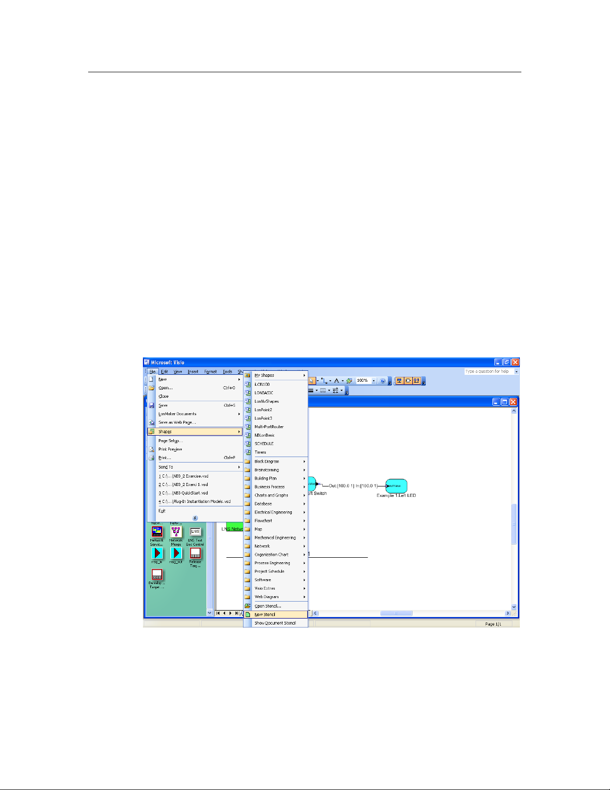
Additional Device Developmen t St e p s
After you create your device application and successfully test your device in a network, you can
perform the following additional steps in the device development process, which are summarized in
the following sections:
• Create an IzoT CT stencil.
• Create an IzoT device plug-in.
• Create an HMI.
• Create a device installation application
• Apply for L
Creating an IzoT CT Stencil
You can create a IzoT CT stencil for your device to make it easier for network integrators to install. A
IzoT CT ste ncil should c ontain a c ustom IzoT CT shape for your device and for each functional block
in the device interface. These custom shapes can then be provided to net work integrat ors so that they
can quickly integrate your device into their L
To create a IzoT CT stencil for your device, you do the following:
1. Create a new IzoT CT stencil. To do this follow these steps:
a. Open the IzoT CT drawing containing the NodeBuilder devi ce for which you want to make
ONMARK certification for your device.
ONWORKS networks using the IzoT Commissioning Tool.
custom shapes.
b. Click File, point to Stencils, and then cli ck New Stencil.
c. A blank IzoT CT stencil named Stencil is added to the Shapes window.
2. Create a custom device shape. To do this follow these steps:
a. Right-click the NodeBuilder device in the IzoT CT drawing page and then select Properties
on the short cut menu.
60 Creating and Opening IzoT NodeBu il der Pr ojec ts
Page 75

b. The Device Properties dialo g opens with the Attributes tab selected. This dialog allows you
to read and write to the properties of the IzoT CT device.
c. In the Device Name property, enter the name to be shown for the custom device shape in your
IzoT CT stencil.
d. Click the Basic Properties tab.
IzoT NodeBuilder FX User's Guide 61
Page 76

e. Set the Location and Ping Interval properties to the values to be saved with the custom
device shape in your IzoT CT stencil. See the IzoT CT online help file for more informatio n
on these properties. Note that changes made to the Description are not saved in the custom
device shape.
f. Click the Advanced Properties tab.
62 Creating and Opening IzoT NodeBu il der Pr ojec ts
Page 77

g. Set the Non-group Receive Timer property to the value to be saved with the custom device
shape in your IzoT CT stencil. See the Iz oT CT online help file for more infor mation on this
property.
h. Click OK.
i. Drag your NodeBuilder device to your IzoT CT stencil. A new custom IzoT CT master shape
with the device name specified in step c appears in the stencil.
j. Click the disk icon (
CT stencil file (.vss extension), and then sa ve your IzoT CT stencil.
IzoT NodeBuilder FX User's Guide 63
) on the stencil’s title bar. Specify a name and location for your IzoT
Page 78
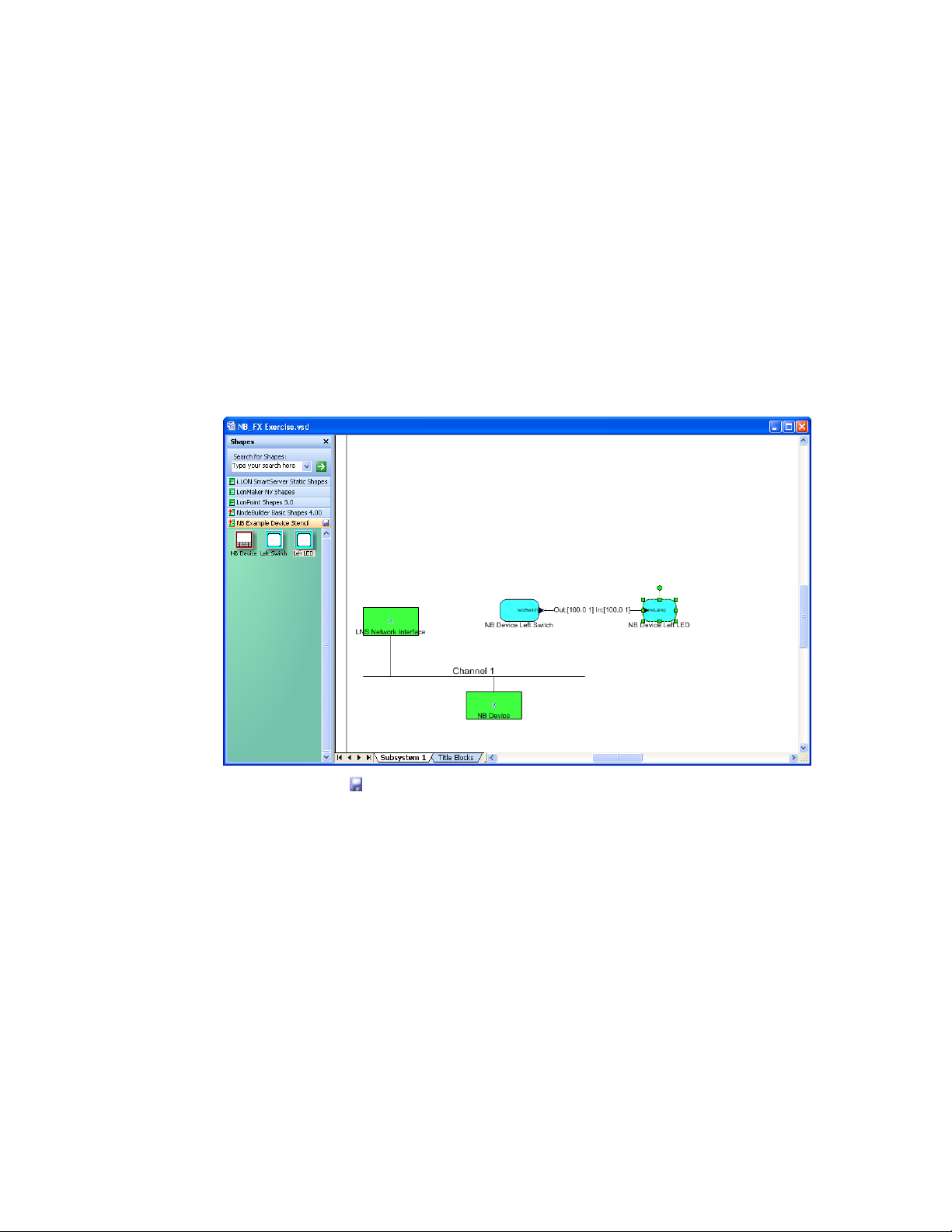
3. Create custom functional block shapes. Custom functional block shapes let you provide network
integrators with functional block shapes that have built-in network variable shapes. To do this
follow these steps:
a. Verify that functional block shapes for each functional block defined by the device interface
have been added to the IzoT CT drawing. To create a functional block shape, drag a
Functional Block shape from the NodeBuilder Basic Shapes 4.00 stencil on the left of the
IzoT CT window to the d r awing, and then complete the Functional Block wizard.
b. Configure the default network variable and configuration property values for the custom
functional block using the IzoT browser or an IzoT d evice plug-in (if you have created one for
your device). You can create several versions of the same functional block for different
configurations of that functiona l block.
c. Drag each functional block shape to your IzoT CT stencil. New custom IzoT CT master
shapes with the functional block names specified in the Functional Block wizard appear in the
stencil.
d. Click the disk icon (
Note: Custom IzoT CT shapes can contain multiple functional blocks, devices, and connections. For
example, you can create custom IzoT CT shapes for two connected functional blocks, or for a device
and all of its configured functional blocks. To do this, select multiple shapes and drag and drop them
to a custom stencil. See the IzoT Commissioning Tool User’s Guide for more information on creating
complex custom IzoT CT shapes.
) on the stencil’s title bar to save your IzoT CT stencil.
Creating an IzoT Device Plug-in
You can create an IzoT device plug-in to simplif y and automate the installation of yo ur devices for
network integrators. An IzoTdevice plug-in is an application that implements the IzoTPlug-in API.
IzoTdevice plug-ins are typicall y written in a .NET programming language such as C# or Visual Basic
.NET, but you can write an IzoTdevice plug-in in any development environment that allows the
creation of an (COM) automation server for Windows. For more information on writing IzoTdevice
plug-ins and the IzoTPlug-in API, see the OpenLNS Plug-in Programmer’s Guide.
64 Creating and Opening IzoT NodeBu il der Pr ojec ts
Page 79

Developing an HMI
You can create a human machine interface (HMI) for your device so that end users can monitor and
control it. You will typically crea te a n HMI if you are building a complete s ystem that requires one;
however, if your device is installed by integrators where ea ch installation is unique, the int e gra tors will
typically develop the required HMIs.
You can use the IzoT C ommissioning Tool to design a simple HMI for your device. With the IzoT
Commissioning Tool, you use the data point shape in the IzoT CT Basic Shapes stencil and standard
Visio shapes to create the HMI. For example, you can create an HMI that displays the current state of
a lamp and provides override switches that le t you manually turn the lamp on and off. For more
information on creating HMIs with data point shapes, see Chapter 6 of the IzoT Commissioning Tool
User’s Guide.
You can use high-end HMI t ools, such as Wonderware’s InTouch or Intellution FIX, to represent more
complex types of network interactions. These tools are developed with a scripting language tuned to
specifically address HMI tasks. In addition, these tools offer components that provide reporting and
analysis, hi story, ala rm logging, event handling, and Internet-enabling.
Creating a Device Installation Application
You can create an installation executable that automatically installs all the files required by your
device into the appropria te locations on your customers’ computers. The files that your applicatio n
should install include the device a pplication (if your device uses downloadable application memory),
the device interface file, user-defined resource files, the IzoT CT stencil, the IzoT device plug-in, and
the HMI. Typically, the installation executable is created using a n in stallation application such as the
InstallShield
If your device will be installed in a managed network (as opposed to a self-installed network), your
customers must have an IzoT, OpenLNS, or an LNS network tool such as the IzoT Commissioning
Tool already installed on their comp uter s. Installing an IzoT, OpenLNS, or an LNS network tool
creates a LonWorks folder that is stored by default in the root directory or program files directory on
the user’s computer (for example, C:\Program Files (x86)\LonWorks). The user, howe ver, can
change the location of the LonWorks folder when they are installing the IzoT, OpenLNS, or LNS tool.
You can locate the LonWorks folder in the Windo ws regi stry at the following location:
®
product.
IzoT NodeBuilder FX User's Guide 65
Page 80

Programmable
The IzoT Commissioning Tool and other IzoT, OpenLNS, and LNS
Device Interface Files
The IzoT Commissioning Tool and other IzoT, OpenLNS, and LNS
HKEY_LOCAL_MACHINE\SOFTWARE\LonWorks\LonWorks Path
The following table lists and describes the files that your installation application should install:
Application Image
Files
(.APB and .NXE)
network tools use programmable application image files to download
the compiled application image to a device. The programmable
application image files have .APB, .NDL, and .NXE exten sions.
On an IzoT NodeBuilder computer, the programmable application
image files are stored in the Development or Release target folder
within the device template folder. For example, the application image
files for the development target in the quick-start exercise in this
chapter are stored in the
C:\Users\Public\Documents\LonWorks\OpenLnsCt\Source\IzoT
NB Exercise\IzoT NB Example Device\Development folder.
Your installation executable must install the .APB files. The .NDL
file is used to support manufacture-time loading of devices and
therefore does not need to be installed; the .NXE file is used to
support legacy network tools and is usually not required. The .APB
file should be installed in a folder where it can be found by the IzoT
network tool o n the target computer. For the IzoT Commissioning
Tool, you can find this location in the Windo ws registry in the
following location (by default, this loca tion is C:\Program Files
(x86)\LonWorks\Import):
HKEY_LOCAL_MACHINE\SOFTWARE\LonWorks\LonMaker for
Windows\NxeSearchPath
Your installation executable should install your .APB file in a
subdirectory labeled with your company name (C:\Program Files
(x86)\LonWorks\Import\YourCompany, for example). Your
installation should search for your company’s folder and, if not found,
it should create a folder with your company’s name.
See Building an Application Image in Chapter 8 for more information
on these programmable application image files.
(.XIF, .XFO*, and
.XFB)
* .XFO file is
optional.
network tools use device interface files (also known as external
interface files) to create IzoT device templates. Device interface files
have .XIF, .XFO, and .XFB extensions.
On an IzoT NodeBuilder computer, the device interface files are
stored in the same Development or Release target folder that c ontains
the programmable application image files for the device.
Your installation executable must install the .XIF and .XFB files.
Installing the .XFO file is optional; however, it speeds up device
template importing for tools that support it such as the IzoT
Commissioning Tool.
Your installation executable should install these device interface files
in a folder where it can be found by the IzoT network tool on the
target computer. For the IzoT Commissioning Tool, you can find thi s
location in the Windows registr y in the following location (by default,
this location is C:\Program Files (x86)\LonWorks\Import):
HKEY_LOCAL_MACHINE\SOFTWARE\LonWorks\LonMaker for
Windows\XifSearchPath
66 Creating and Opening IzoT NodeBu il der Pr ojec ts
Page 81

Your installation executable should install your device interface files
Device Resource Files
Resource files are the files created by the NodeBuilder Resource
OpenLNS Device
If you have created an IzoT device plug-in, it should be installed and
IzoT CT Stencil
If you have created an IzoT CT stencil containing custom shapes for
HMI Application
If you have created an HMI for your device, it should be installed and
in a subdirectory labeled with your company name (C:\Program Files
(x86)\LonWorks\Import\YourCompany, for example). Your
installation should search for your company’s folder and, if not found,
it should create a folder with your company’s name.
See Building an Application Image in Chapter 8 for more information
on these device interface files.
(.TYP, .FMT, .FPT)
Plug-in
Editor that contain networ k variable and configuration property type
information and functional pr ofile definitions. You must install all
resource files that are used by your device.
The location of the resource files on the IzoT NodeBuilder computer
can be found by starting the resource editor and finding the folder that
contains the resource file set you want to include in the installation.
For each resource file set, you must install the type file (.TYP
extension), the format file (.FMT extension), the functio nal profile
file (.FPT extension), and any language resource file (language
resource file extensions vary by language as described in the
NodeBuilder Resource Editor User’s Guide. Uninstalling a device
should not remove manufacturer resource files because they may be
used by other devices from the manufacturer.
Resource files should be installed to the LonWorks\Types folder, in a
subdirectory labeled with your company name (C:\Program Files
(x86)\LonWorks\Types\YourCompany, for example).
registered by your installation. See the OpenLNS Plug-in
Programmer’s Guide for more information.
your device, it should be installed in the LonWorks\LonMaker\Visio
folder in a subdirectory labeled with your company name (C:\
Program Files (x86)\LonWorks\LonMaker\Visio\YourCompany,
for example). See
Creating a LonMaker Stencil earlier in this section
for more information.
registered. See the documenta tion for your installation creation
software and your HMI development tool for more information on the
steps this entails.
Applying for LONMARK Certification
LONMARK International is an independent, no n-profit organization that oversees LONWORKS
technology and related standards. If your device will be installed by integrators, you will want to
apply for L
devices for their projects. L
ONMARK certification for your device since most integrators require LONMARK certified
ONMARK certified devices are assured to be compliant with LONMARK
standard and can be easily integrated into L
multiple vendors. For information on having your device L
site at www.lonmark.org.
IzoT NodeBuilder FX User's Guide 67
ONWORKS networks with other LONWORKS devices from
ONMARK certified, see the LONMARK Web
Page 82

68 Creating and Opening IzoT NodeBu il der Pr ojec ts
Page 83

Creating and Opening IzoT
NodeBuilder Projects
This chapter describes how to create, open, and copy IzoT NodeBuilder projects, and
how to copy NodeBuilder projects and NodeBuilder device templates to another
computer.
4
IzoT NodeBuilder User's Guide 69
Page 84

Pane
Description
Project
Provides a hierarchical view of all the components in the NodeBuilder
Introduction to the NodeBuilder Project Manager
A NodeBuilder project collects all the information about a set of devices that you are developing. Y ou
will create, manage, and use NodeBuilder projects from the NodeBuilder Project Manager. The
project manager provides an integrated view of your entire project and provides the tools you will use
to define and build your project.
To create a NodeBuilder project, you start the NodeBuilder Project Manager from the IzoT
Commissioning Tool or d ir e c tly from the No deBuilder program folder. Yo u will typically start the
project manager from the IzoT Commissioning Tool because it simplifies the process of assoc ia ting t he
NodeBuilder project with the IzoT CT network.
You can use the same NodeBuilder project with multiple IzoT CT networks, and you can use a IzoT
CT network with multiple NodeBuilder projects; however, you can only use a IzoT CT network with
one NodeBuilder project at a time.
The NodeBuilder Project Manager initially contains three panes: the Project pane (left), the Edit pane
(right), and the Results pane (bottom). These panes can all be moved and resized, and the Project and
Results panes can be closed; however, the NodeBuilder Project Manager displays all the three panes by
default.
The following table describes the three panes in the NodeBuilder Project Manager:
project. The Project pane lets you browse the files used in the
NodeBuilder Project. See the following section for further description
of the Project pane.
70 Creating and Opening IzoT NodeBuilder Projects
Page 85

Edit
Lets you to edit any of the Neuron C s ource files or header files that
Results
The Results pane contains three tabs: Messages, Search Results, and
are used in the project. See Chapter 7, Developing Device
Applications, for more information on using the Edit pane.
Event Log.
• The Messages tab displays compiler and other messages
generated when you build the application image for a
NodeBuilder device template. If any errors or warnings are
generated during the b ui ld, you can double-clic k the m to open the
file containing the error or warning and go to the line of code that
generated the error or warning. See Building an Application
Image in Chapter 8 for more information on using the Messages
tab in the Results pane.
• The Search Results tab displays the results of a Find in Files
search. You can double-click any of these results to open the file
containin g t he search text and go to the line containing t he search
text. See Searching Source Files, in Chapter 7 for more
information on using the Search Results tab in the Resul ts pane.
• The Event Log contains debugger event messages. See Chapter
10, Debugging a Neuron C Application, for more information on
using the Event Log tab in the R esults pane.
Using the Project Pane
The Project pane appears on the left side of the NodeBuilder Project Manager by default. The Project
pane provides a hierarchical view of all the components in the NodeBuilder project. You can use the
Project pane to browse and open the files in your NodeBuilder Project.
The top level of the Project pane is always a project folder labeled Project ‘<Project Name>‘:. You
can right-click the Project folder t o see a short cut menu wit h the follo wing options :
IzoT NodeBuilder User's Guide 71
Page 86

Settings
Opens the NodeBuilder Project Properties dialo g with the Project
Properties
Displays file properties of the NodeBuilder project file (.NbPrj
tab selected. The Project tab displays the project settings.
extension). The properties include the file name, location, size, and
the dates on which the file was create d, last modified, and last
accessed.
The Project folder may also co ntain t he following three folders: Device Templates, Devices, and
Hardware Templates.
• The Device Templates folder contains all of the device templates that have been created in this
NodeBuilder project. See Creating Device Templates in Chapter 5 for more information on device
templates.
• The Devices folder contains a list all devices in IzoT CT drawings that have been associated with
device templates in this NodeBuilder project. See Building an Application Image in Chapter 8 for
more information. Note that the Devices folder will not appear if the NodeBuilder project is not
associated with an IzoT CT networ k.
• The Hardware Templates folder contains a list of the hardware templates available in this
NodeBuilder project. See Using Hardware Templates in Chapter 5 for more information on
hardware templates.
Creating a NodeBuilder Project
To create a NodeBuilder project, you must first start the NodeBuilder Project Manager. You can start
the NodeBuilder Project Manager from the IzoT Commissioning Tool, or you can start it standalone
directly from the NodeBuilder program folder. You will typically start the project manager from the
IzoT Commissioning Tool because it simplifies the process of associating the NodeBuilder project
with the IzoT CT network.
72 Creating and Opening IzoT NodeBuilder Projects
Page 87
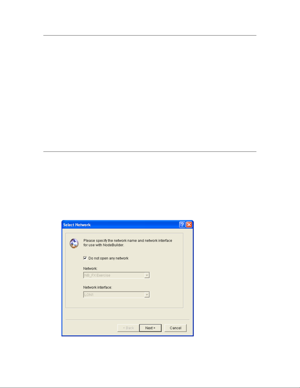
Creating a NodeBuilder Project from IzoT CT
You can create a NodeBuilder project by starting the NodeBuilder Project Manager from the IzoT
Commissioning Tool. To do this, follow these steps:
1. Create or open a IzoT CT drawing. See the IzoT Commissioning User’s Guide for more
information on creating and opening IzoT CT drawings. If you will want to load the application
you develop into a device, make sure the IzoT CT computer is attached to the network.
2. Click Add-Ins, click Open LNS CT, and the n click NodeBuilder. The NodeBuilder Project
Manager starts. If you have not previously created a NodeBuilder project for this network, the
New Project wizard automatically starts.
Note: If you have previously created a project for this network and you want to create a new
project, click File and then click Create Project.
3. Enter project information into the wizard as described in steps 5–9 in the ne xt s ection, Creating a
NodeBuilder Project from the NodeBuilder Project Manager.
Note: You can also start the IzoT NodeBuilder tool from the IzoT Commissionin g tool’s New Device
Wizard. See Starting the IzoT NodeBuilder tool from the New Device Wizard later in this chapter for
more information on how to do this.
Creating a NodeBuilder Project from the NodeBuilder Project Manager
You can create a NodeBuilder project by starting the NodeBuilder Project Manager standalone. To do
this, follow these steps:
1. Open the NodeBuilder Project Manager. To do this, click Start on the taskbar, point to
Programs, point to Echelon No deB uilder, and then cli ck NodeBuilder Development Tool. The
NodeBuilder Project Manager starts.
2. Click File and then click Create Project. The New Project wizard starts with the Select Network
dialog.
3. To associate an existing IzoT CT network with your NodeBuilder project, clear the Do Not Open
Any Network check box if it is selected, select an existing IzoT CT network in the Network
IzoT NodeBuilder User's Guide 73
Page 88

property, and then select the IzoT network interface to be used for communication between the
IzoT CT network and your NodeBuilder devi ce in the Network Interface property.
Alternatively, you can select the Do Not Open Any Network check box to create a new project
that is not associated with a IzoT CT network, and disable automatic IzoT device template creation
and automatic load after build.
4. Click Next.
5. The Specify New Project Name dialog opens.
6. In the Project Name property, enter the name of your new NodeBuilder project. If you specified
a IzoT CT network to be associated with the NodeBuilder project in the Select Network dialog,
the default Project Name is that of the selected IzoT CT network. You can accept this default
name or enter a new one.
Project files with this name and .NbPrj, .NbOpt, and .NbWsp extensions will be created in the
project folder specified in the Location property. The project folder is stored in the
C:\Users\Public\Documents\LonWorks\OpenLnsCt \Source\<Project name> folder by default.
You can click the button t o the right of the Location property to specify a different location.
If you specified a LonMaker network to be associated with the NodeBuilder project in the Select
Network dialog, the Set as Default Project check box is selected. This means that this
NodeBuilder project is automatically opened when the IzoT NodeBuilder tool is started from the
selected IzoT CT network. If you selected the Do Not Open Any Network check box in the
Select Network dialog, the Set as Default Project check box is unavailable.
7. Click Next. The Specify Project Default Settings dialog opens.
74 Creating and Opening IzoT NodeBuilder Projects
Page 89
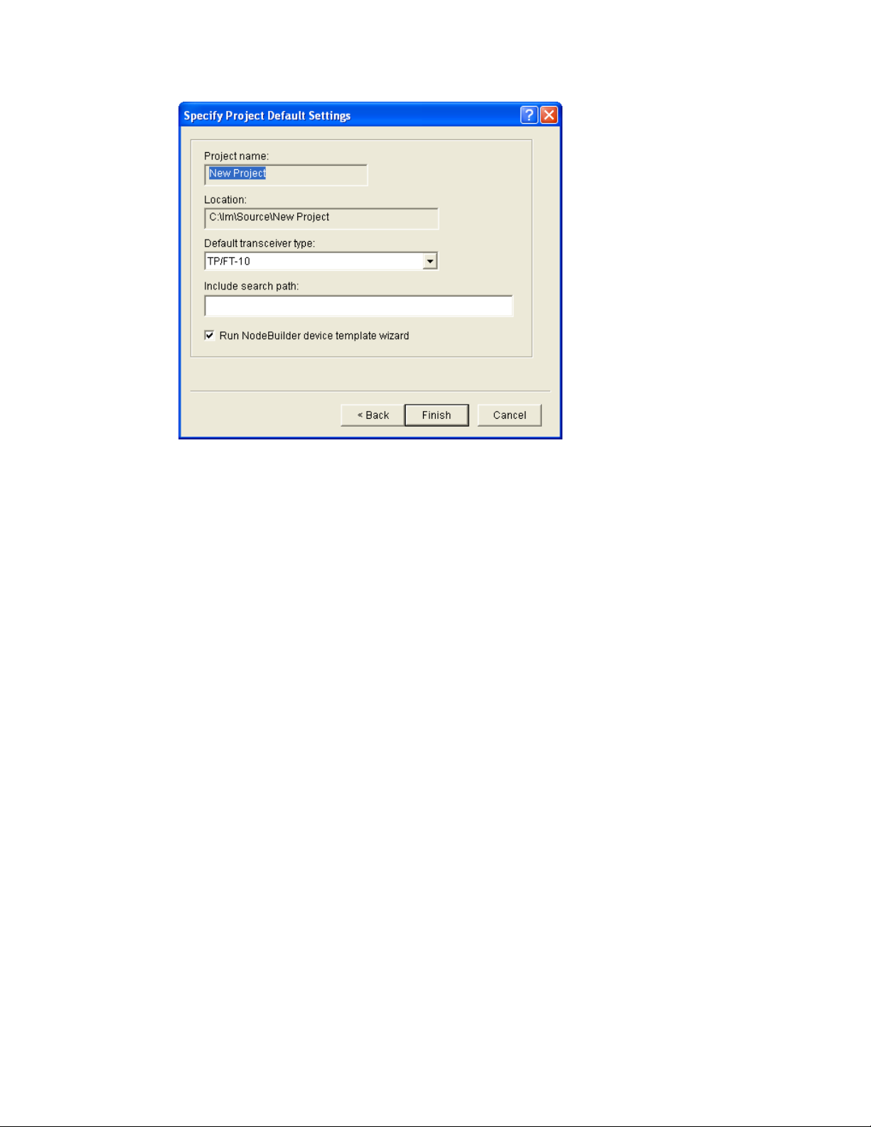
8. Specify the following properties:
Project Name The name of the project as specified in the Specify New Project
Name dialog. This is a read-only field.
Location The location of the project folder as specified in the Specify New
Project Name dialog. This is a read-only field.
Default Transceiver
Type
Include Search
Path
Run Device
Template Wizard
The transceiver type to be used for Hardware Templates that specify
“default” for the transceiver type. The default transceiver type is
TP/FT-10. See the Using Hardware Templates section i n Chapter 5
for more information on hardware templates.
An optional semi-colon separated list of directories to be searched for
include files when a NodeBuilder project is compiled. By default,
only the device template source file and the Neuron C standard
include file directories will be searched for include files. If relative
path names are specified, they are relative to the location of the
NodeBuilder project directory (location of the .NbPrj project file).
Note that this list applies to the entire project. By default, this
property is blank.
Automatically opens the Device Template Wizard immediately after
you click Finish. The Device Template Wizard guides you through
the process of creating the first NodeBuilder device template for this
project. See Creating Device Templates in Chapter 5 for more
information. This option is selec te d by default.
9. Click Finish. If you selected the Run Device Template Wizard check box in the Specify
Project Default Settings dialog, the Device Template Wizard opens. Proceed to the Specifying
the Device Template Name section in Chapter 5 to create a device template.
IzoT NodeBuilder User's Guide 75
Page 90
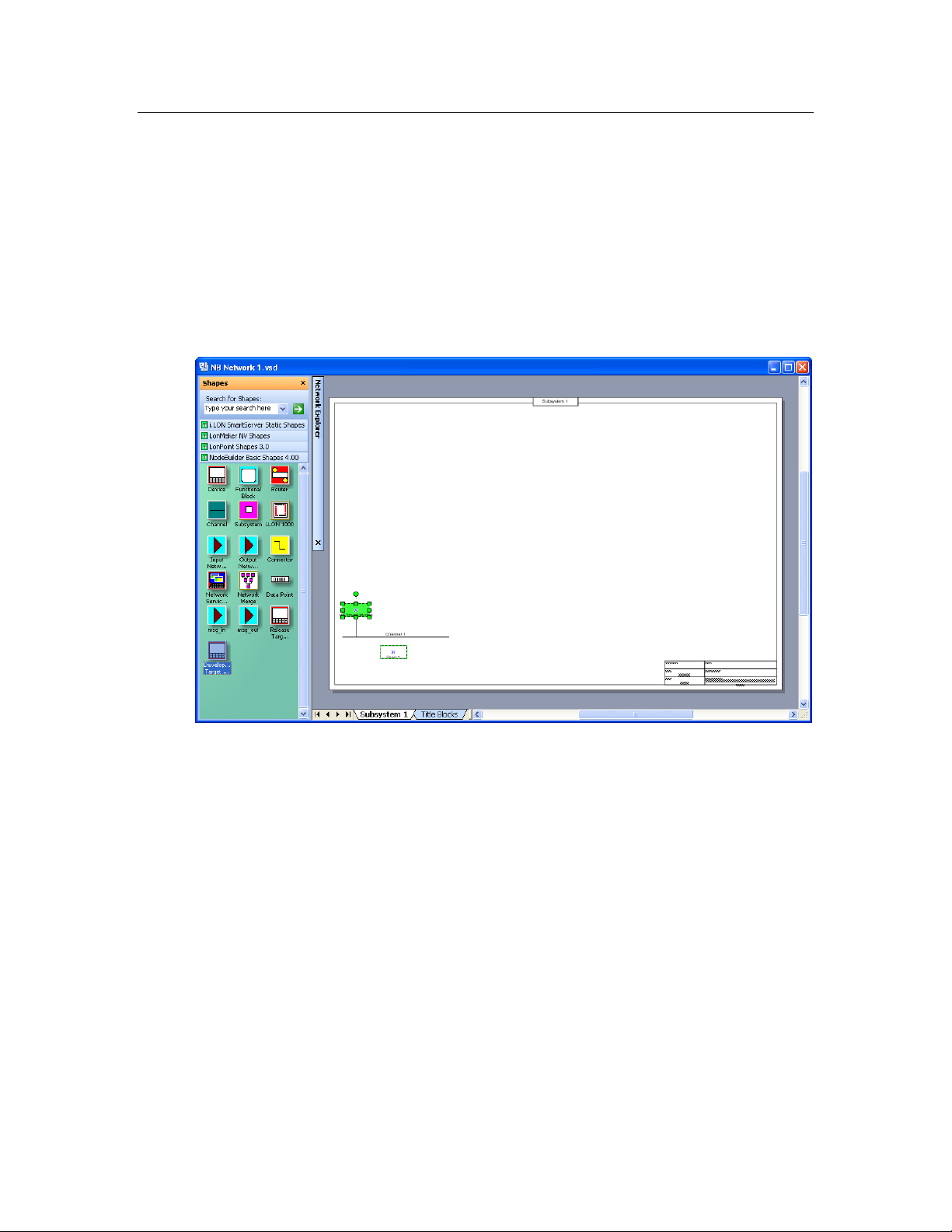
Creating a NodeBuilder Project from the New Device Wizard
You can create a NodeBuilder project from the New Device Wizard in the IzoT Commissioning Tool.
To do this, follow these steps:
1. Create or open an IzoT CT network. See the IzoT Commissioning User’s Guide for more
information on creating and opening IzoT CT networks. If you plan on downloading your device
application to a device, make sure that the IzoT CT computer is attached to the network.
2. Drag a Development Target Device or a Release Target Device shape from the NodeBuilder
Basic Shapes 4.00 stencil to your networ k drawing. Us e a Development Target Device if you
are building to a NodeBuilder hardware platform; use a Release Target Device if you are building
to the release hardware. You can drop the shape anywhere, but a good location is just below the
Channel 1 sha pe on your drawing.
3. The New Device Wizard opens. In the Device Name property, enter the device name, select the
Commission Device check box, and then select the Create New Device Template check box
under NodeBuilder Device Template.
76 Creating and Opening IzoT NodeBuilder Projects
Page 91

4. Click Next. The next page in the New Device Wizard lets you select the NodeBuilder device
template.
5. Click Start NodeBuilder to create a new NodeBuilder project. The IzoT NodeBuilder tool starts
automatically.
6. The New Project wizard opens.
IzoT NodeBuilder User's Guide 77
Page 92

7. Accept the default Create a New NodeBuilder Project option, and then click Next.
8. Accept the default No deBuilder Project Name, which is the same name as the IzoT CT network,
and then click Next.
9. Accept the defaults in the Specify Default Project Settings dialog, and then click Finish.
10. The NodeBuilder New Device Template wizard starts. Proceed to the Specifying the Device
Template Name section in Chapter 5 to create a device template.
Opening a NodeBuilder Project
To open an e xisting NodeBuilder project, you must first start the NodeBuilder Project Manager if it is
not already running. You can start the NodeBuilder Project Manager from the IzoT Commissioning
Tool, or directly from the NodeBuilder program folder. You will typically start the project manager
from the IzoT Commissioning Tool since that simplifies assoc ia ting the NodeBuilder project with the
IzoT CT network.
Opening a NodeBuilder Project from the IzoT Commissioning Tool
You can open a NodeBuilder project by starting the NodeBuilder Project Manager from the IzoT
Commissioning Tool. To do this, follow these steps:
1. Create or open an IzoT CT drawing. See the IzoT Commissioning User’s Guide for more
information on creating and opening IzoT CT drawings. If you plan on downloading your device
application to your device, make sure the IzoT CT computer is attached to the network.
2. Click Add-Ins, click OpenLNS CT, and then click NodeBuilder. The NodeBuilder Project
Manager starts. If you have not previously created a NodeBuilder project for this network, the
New Project wizard automatically starts with the NodeBuilder Project dialog displayed.
Note: If you have previously created a NodeBuilder project for this network, the default projec t
for the network opens. To open a different project, click File, click Open Project, and then skip
to step 4.
78 Creating and Opening IzoT NodeBuilder Projects
Page 93

3. In the NodeBuilder Project dialog, select the Open an Existi ng NodeBuilder Project option and
then click Next.
4. The Select NodeBuilder Project File dialog o pens. Click the button to the right of the Project
File property, browse to and select the desired project folder
(C:\Users\Public\Documents\LonWorks\OpenLnsCt \Source\<Project Folder> by default),
and then select the project file (.NbPrj extension) in the project folder.
5. Click Finish.
Notes:
• You can open a project and start the New Device Template wizard at the same time by
dragging a Development Target or Release Target device shape from the NodeBuilder
Basic Shapes 4.00 stencil to your networ k drawing.
IzoT NodeBuilder User's Guide 79
Page 94
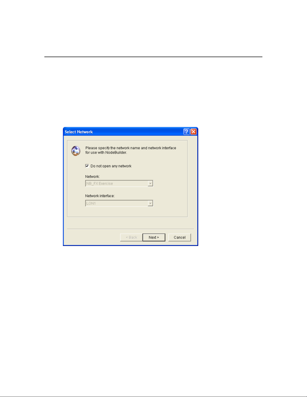
• You can open specific windows within the default project by right-clicking a Development
Target or Release Target device shape in the IzoT CT drawing, pointing to Custom, and
then clicki ng Edit Source, NodeBuilder Properties, Build, or Debug o n t he shortcut menu.
Opening a NodeBuilder Project from the NodeBuilder Project Manager
You can open a NodeBuilder project by starting the NodeBuilder Project Manager standalone. To do
this, follow these steps:
1. Open the NodeBuilder Project Manager. To do this, click Start on the taskbar, p oint to
Programs, point to Echelon NodeBuilder, and then click No deB uilder Development Tool. The
NodeBuilder Project Manager starts.
2. Click File and then click Open Project. The New Project wizard starts with the Select Network
dialog.
3. To associate an existing IzoT CT network with your existing NodeBuilde r project , clear the Do
Not Open Any Netw ork check box if it is selected, select an existing IzoT CT network in the
Network property, and then select the IzoT network interface to be used for communication
between the IzoT CT network and your N odeBuilder device in t he Network Interface property.
Click Next.
Alternatively, you can select the Do Not Open Any Network check box to open a NodeBuilder
project but not associate it with an IzoT CT network, and disable automatic IzoT device template
creation and automatic load after build. Click Next.
4. The Select NodeBuilder Project File opens.
80 Creating and Opening IzoT NodeBuilder Projects
Page 95

5. If you have previously associated a IzoT CT network with this NodeBuilder project, it appears in
the Project File property.
6. To select a different NodeBuil der project, click the button to the right of t he Project File property,
browse to and select your project folder (C:\Users\Public\Documents\LonWorks\OpenLnsCt
\Source\<Project Folder> by default), and then select the project file (.NbPrj extension) in t he
project folder.
7. Optionally, you can select the Set as Default Project check box to specify this NodeBuilder
project as the default when the IzoT NodeBuilder tool is started from the IzoT Commissioning
tool.
8. Click Finish.
Copying NodeBuilder Projects
You can copy a NodeBuilder project to another computer using IzoT CT, or by manually copying the
NodeBuilder project files. After you copy a NodeBuilder project, you must also copy any user-defined
resource files used by the device template in the project from the source computer to the target
computer, and then install and register yo ur user-defined resource files on the target computer. See
Copying User-Defined Resource Files for more information on how to do this.
Using the IzoT Commissioning Tool to Backup and Restore a NodeBuilder Project
You can copy a NodeBuilder project to another computer by backing up the project files on the source
computer and restoring them on the t arget computer with the IzoT Co mmissioning Tool. To do this,
follow these steps:
1. Ensure that the source and target computers have the same versions of the IzoT NodeBuilder tool
and the IzoT Commissioning Tool.
2. On the source computer, start the IzoT Commissioning Tool. To do this, click Start on the
taskbar, point to Programs, point to Echelon OpenLN S CT, and then select OpenLNS
Commissioning Tool. The OpenLNS CT Design Manager opens.
IzoT NodeBuilder User's Guide 81
Page 96

3. In the Database Name property under Existing Network, select the IzoT CT network design
associated with the NodeBuilder project to be copied and then click Backup.
4. The OpenLNS CT Backup dialog opens.
5. Select the Backup Drawing, Backup Database, Backup NodeBuilder Project check boxes
under Backup Selec tion (the Backup Drawing and Backup Database check boxes are selected
by default), and then click OK.
82 Creating and Opening IzoT NodeBuilder Projects
Page 97

6. The IzoT CT drawing, IzoT network database, and the NodeBuilder project are all stored in a
single IzoT CT backup file (.zip extension) that is specified in the Backup File property
(C:\Users\Public\Documents\LonWorks\OpenLnsCt \Backup\<IzoT CT network>\<IzoT CT
network>_<index>.zip by default).
7. After the backup has been created, copy the IzoT CT backup file from the source computer to a
USB drive, another removable media, or a shared network drive with read/write permissions.
8. On the target computer, start the IzoT Commissioning Tool and then
9. Click Restore. The OpenLNS CT Restore dialog opens.
10. Click Browse to specify the location of the Iz oT CT backup file, and then click OK. The
Confirm Restore dialog opens.
IzoT NodeBuilder User's Guide 83
Page 98

11. Click OK. The IzoT CT drawing, IzoT network database, and the NodeBuilder project are copied
to the target computer. The NodeBuilder project is associated with the IzoT CT network.
12. A message appears informing you that the network restore operation has been completed, and
prompting you to select whether to open the IzoT CT network in order to recommission devices
that have changed since the net work was backe d up.
• Click Yes if you made any changes to the network since i t was backe d up. This prevents the
network from behaving unpredictably if the IzoT CT network design is not in sync with the
physical devices. Proceed to recommission and resynchronize the network.
• Click No only if changes have not been made to the configuration of the existing physical
devices on the network since it was backed up. This happens if the IzoT Commissioning Tool
was OffNet the entire time, or if you added new devices and functional blocks but did not
modify any existing devices or functional blocks. The IzoT CT drawing will not be opened.
See the IzoT Commissioning User’s Guide for more information on backing up and restoring a
ONWORKS Network Design.
L
Manually Copying NodeBuilder Project Files
You can manually the entire NodeBuilder project. To do this, follow these steps:
1. Ensure that the source and target computers have the same versions of the IzoT NodeBuilder tool
and the IzoT Commissioning Tool.
2. On the source computer, copy the entire NodeBuilder Project folder to a USB drive, another
removable media, or a shared network drive with read/write permissions. By default, the
NodeBuilder Project folder is stored in the C:\Users\Public\Documents\LonWorks\OpenLnsCt
\Source directory and has the same name as the NodeBuilder project. The NodeBuilder Project
folder contains subdirectories for each device template in the NodeBuilder project.
3. On the source computer, copy any user-defined hardware templates and custom libraries to the
USB drive, another removable media, or a shared network drive with read/write permissions. By
default, user-defined hardware templates are stored in the C:\Program Files
(x86)\LonWorks\NodeBuilder\Templates\Hardware\User directory.
4. Copy the NodeBuilder Project backup to the
C:\Users\Public\Documents\LonWorks\OpenLnsCt \Source directory on the target computer.
84 Creating and Opening IzoT NodeBuilder Projects
Page 99

5. Copy the user-defined hardware template backup to the C:\Program Files
(x86)\LonWorks\NodeBuilder\Templates\Hardware\User directory on the target computer.
You need to create a User folder i n the Hardware directory if one does not already exist.
6. Copy the library backup to the same folder as they were located on the source computer. If this is
not possible, you can re-add them to the project as described in Inserting a Library into a
NodeBuilder Device Template.
7. Start the IzoT NodeBuilder tool as described in Opening a NodeBuilder Proj ec t earlier in this
chapter and browse to and open the NodeBuilder Project file (.NbPrj extension).
Copying NodeBuilder Devic e Temp lat es
You can copy NodeBuilder device templates to another computer. To do this, follow these steps:
1. Ensure that the source and target computers have the same versions of the IzoT NodeBuilder tool.
2. If the NodeBuilder project that will contain the device templates has not been created on the target
computer, create it as described in Creating a NodeBuilder Project earlier in this chapter
3. On the source computer, copy the device template folders to a USB drive, another removable
media, or a shared network drive with read/write permissions. By default, the device templates
within a given project are stored in individual folders in the
C:\Users\Public\Documents\LonWorks\OpenLnsCt \Source\<NodeBuilder Project> directory
that have names corresponding to their respective NodeBuilder device templates.
4. On the source computer, copy any user-defined hardware templates and custom libraries to the
USB drive, another removable media, or a shared network drive with read/write permissions. By
default, user-defined hardware templates are stored in the C:\Program Files
(x86)\LonWorks\NodeBuilder\Templates\Hardware\User directory.
5. Copy the device template backups to the C:\Users\Public\Documents\LonWorks\OpenLnsCt
\Source\<NodeBuilder Project> directory of the target NodeBuilder project on the target
computer.
6. Copy the user-defined hardware template backup to the C:\Program Files
(x86)\LonWorks\NodeBuilder\Templates\Hardware\User directory on the target computer.
You need to create a User folder i n the Hardware directory if one does not already exist.
7. Copy the library backup to the same folder as they were located on the source computer. If this is
not possible, you can re-add them to the project as described in Inserting a Library into a
NodeBuilder Device Template.
8. Copy any user-defined resource files from the source computer to the target computer, and then
install and register the resource files on the target computer. See Copying User-Defined Resource
Files for more information on how to do this.
9. On the target computer, open the IzoT NodeBuilder tool.
10. Right-click the Device Templates folder in the Project Pane on the left side of the NodeBuilder
Project Manager, and then click Insert on the shortcut menu.
IzoT NodeBuilder User's Guide 85
Page 100
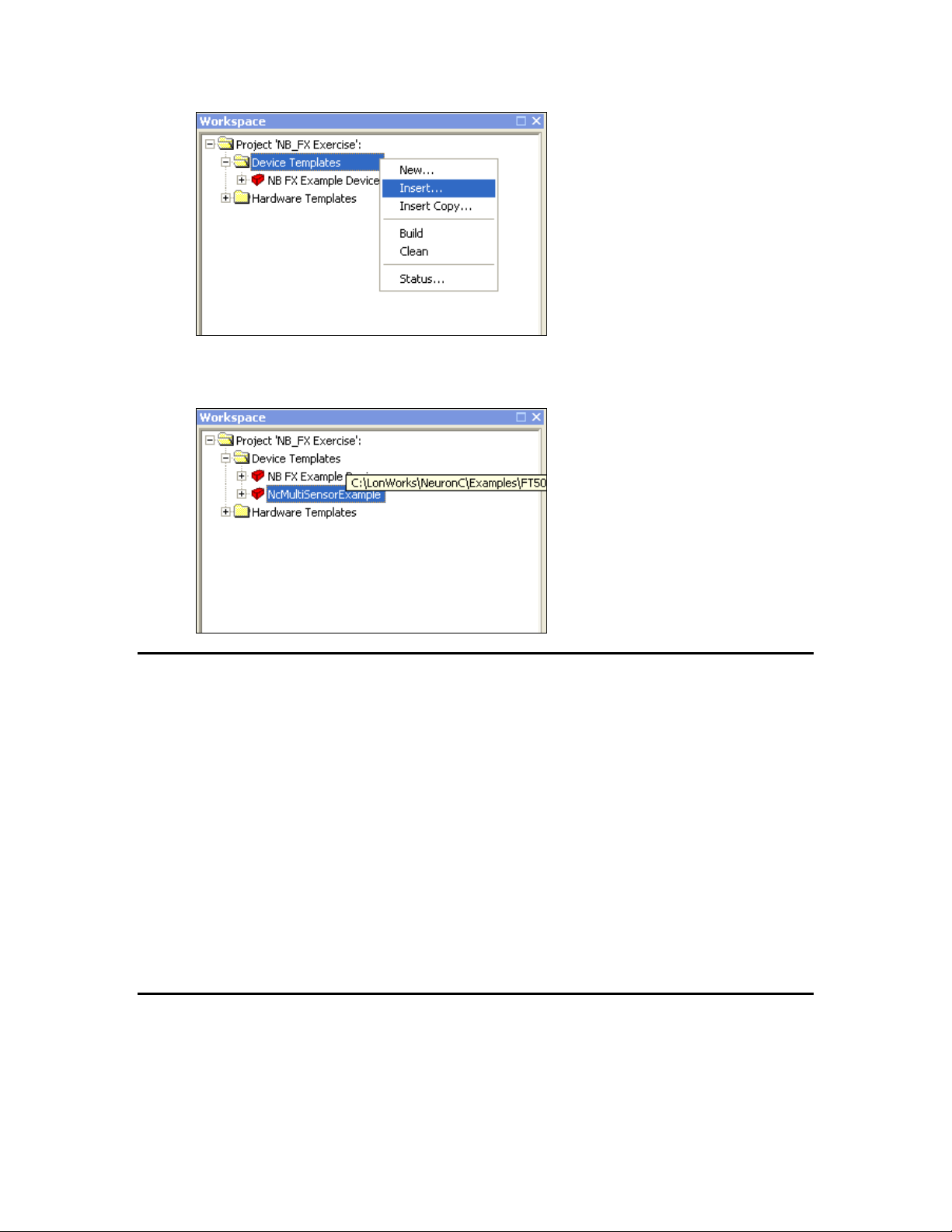
11. Browse to and open the device template folder backed up in step 3, and then select the
NodeBuilder device template file (.NbDt ex ten sion). T he device template is added to the
NodeBuilder project under the Device Templates folder in the Project Pane.
Copying User-Defined Resource Files
After you copy a NodeBuilder project or a NodeBuilder device template to another computer, you
must also copy any user-defined resource files on the source computer to the target computer, and then
install and register the resource files on the target computer. User-defined resource files include the
network variable types, configuration property types, functional profiles, enumerations, languages, and
formats that you have created in your resource file set. To copy resource files to another computer,
follow these steps:
1. On the source computer, copy the resource folder co ntaining yo ur user-defined resource files to a
USB drive, another removable media, or a shared network drive with read/write permissions. By
default, your resource folder is in the C:\Program Files (x86)\LonWorks\types\user directory on
your computer.
2. Copy the user-defined resource file backup to the C:\ Program Files (x86)\LonWorks\types\user
directory on the target computer.
See Using the Resource Pane in Chapter 6 for more information on resource folders, resource file sets,
and resources.
Viewing and Printing NodeBuilder XML Files
Many of the files created by the IzoT NodeBui l der tool are XML files. These files can be viewed and
printed using a variety of tools including Internet Explorer or Micro so ft Excel. This can be useful for
generating printed summaries of the options contained in these files. Do not change the contents of
these files. To open one of these files, r ight-click the file in W indows Explorer and the n click Open
86 Creating and Opening IzoT NodeBuilder Projects
 Loading...