

Page 1

IzoTTM
Commissioning Tool
User’s Guide
Design, install, operate, and maintain IzoT and LONWORKS
networks with the IzoT Commissioning Tool.
®
078-0509-01A
Page 2

Echelon, LON, LONWORKS, IzoT, LonTalk,
Neuron, LONMARK, 3120, 3150, LNS,
LonMaker, LonSupport and the Echelon
logo are trademarks of Echelon Corporation
that may be registered in the United States
and other countries.
Other brand and product names are trademarks or
registered trademarks of their respective holders.
Neuron
Chips and other OEM Products were not
designed for use in equipment or systems which involve
danger to human health or safety or a risk of property
damage and Echelon assumes no responsibility or
liability for use of the Neuron
Chips in such applications.
Parts manufactured by vendors other than Echelon and
referenced in this document have been described for
illustrative purposes only, and may not have been tested
by Echelon. It is the responsibility of the customer to
determine the suitability of these parts for each
application.
ECHELON MAKES NO REPRESENTATION, WARRANTY, OR
CONDITION OF ANY KIND, EXPRESS, IMPLIED, STATUTORY,
OR OTHERWISE OR IN ANY COMMUNICATION WITH YOU,
INCLUDING, BUT NOT LIMITED TO, ANY IMPLIED
WARRANTIES OF MERCHANTABILITY, SATISFACTORY
QUALITY, FITNESS FOR ANY PARTICUL AR PURP OSE,
NONINFRINGEMENT, AND THEIR EQUIVALENTS.
No part of this publication may be reproduced, stored in
a retrieval system, or transmitted, in any form or by any
means, electronic, mechanical, photocopying,
recording, or otherwise, without the prior written
permission of Echelon Corporation.
Printed in the United States of America.
Copyright ©1997–2014 by Echelon
Corporation.
Echelon Corporation
www.echelon.com
ii Preface
Page 3

Table of Contents
Preface ................................................................................................... xi
Purpose .......................................................................................................... xii
Audience ......................................................................................................... xii
System Requirements .................................................................................... xii
IzoT Commissioning Tool Documentation ...................................................... xii
For More Information and Technical Support ................................................ xiii
Content .......................................................................................................... xiv
1 Introduction ....................................................................................... 1
Introduction to the IzoT Commissioning Tool .................................................. 2
New Features .................................................................................................. 2
No-Cost Device Installation ....................................................................... 2
Automated Product Activation ................................................................... 3
Annual Product Maintenance .................................................................... 3
Increased Device Compatibility ................................................................. 3
Longer Database Directory Paths ............................................................. 3
Improved Windows Compatibility .............................................................. 3
Additional OpenLNS Events ..................................................................... 3
New IzoT Commissioning Tool Menus ..................................................... 3
IzoT Commissioning Tool Versions ................................................................. 4
IzoT Commissioning Tool Network Designs .................................................... 5
OpenLNS Network Database .................................................................... 5
OpenLNS CT Drawing .............................................................................. 5
LONWORKS Basics ........................................................................................... 5
Networks ................................................................................................... 5
Devices ..................................................................................................... 5
Protocol ..................................................................................................... 5
Device Templates ..................................................................................... 6
Channels ................................................................................................... 6
Routers ...................................................................................................... 6
Applications ............................................................................................... 6
Network Variables ..................................................................................... 6
Configuration Properties ........................................................................... 7
Functional Blocks ...................................................................................... 8
Functional Profiles..................................................................................... 8
Standard Network Variable and Conf iguration Property T ypes ......... 8
User-defined Standard Network Variable and Configur ation
Property Types ..................................................................................... 9
Subsystems ............................................................................................... 9
Supernodes ............................................................................................... 9
Visio Basics ..................................................................................................... 9
2 Installing and Activating the IzoT Commissioning Tool .............. 12
Ordering the IzoT Commissioning Tool ......................................................... 13
Installing and Activating the IzoT Commissioning Tool ................................. 13
Manually Activating IzoT Commissioning Tool .............................................. 20
3 Getting Started ................................................................................ 26
Design Overview ........................................................................................... 27
Defining Network Requirements and Organization ................................. 27
Selecting a Network Installation Scenario .............................................. 27
Engineered System Scenario ........................................................... 27
Ad-Hoc System Scenario ................................................................. 28
IzoT Commissioning Tool User’s Guide iii
Page 4

Determining User Permissions ............................................................... 28
Optimizing IzoT Commissioning Tool Network Performance ................. 28
Drawing Files .................................................................................... 28
Network Changes ............................................................................. 29
Connections ...................................................................................... 29
Sharing the OpenLNS Interface with the L N S DD E Server ............. 29
Functional Blocks ............................................................................. 30
Subsystems ...................................................................................... 30
IzoT Commissioning Tool Design Manager Overview .................................. 30
Options .................................................................................................... 33
New Network Options ............................................................................. 35
IzoT Commissioning Tool Stencils .......................................................... 37
IzoT Commissioning Tool Default Options.............................................. 38
Setting Up a Network Interface...................................................................... 39
Optimizing Network Interface Performance ............................................ 39
Using an IP-852 Network Interface ......................................................... 39
Creating and Opening IzoT Commissioning Tool Networks ......................... 41
Creating an IzoT Commissioning Tool Network Design ......................... 41
Creating an IzoT Commissioning Tool Network from an Existing
OpenLNS Database .................................................................................. 47
Working with Digital Signatures ........................................................ 51
Copying an IzoT Commissioning Tool Network Design.......................... 52
Opening an IzoT Commissioning Tool Network Design ......................... 55
IzoT Commissioning Tool Client Types .................................................. 57
Local Client ....................................................................................... 57
Remote Full Client ............................................................................ 59
Remote Lightweight Client................................................................ 62
Using Network Service Device SmartShapes ............................................... 66
Listing Network Service Devices ...................................................... 67
Upgrading Network Service Devices ................................................ 68
Replacing a Local Network Service Device ...................................... 68
User Profiles .................................................................................................. 68
Creating a New User Profile ................................................................... 69
Changing Passwords .............................................................................. 71
Modifying and Deleting User Profiles ...................................................... 72
Changing User Profiles in an OpenLNS CT Drawing ............................. 72
Using IzoT Commissioning Tool Remotely with User Profiles ................ 73
4 Designing Networks ....................................................................... 75
Creating a LONWORKS Network ..................................................................... 76
Creating an OpenLNS CT Drawing ............................................................... 76
Creating Application Devices .................................................................. 77
Using Automatic Channel Selection for Devices .............................. 81
Changing the Channel of an Application Device .............................. 82
Creating Functional Blocks ..................................................................... 83
Using Automatic Device Selection ................................................... 87
Reassigning a Functional Block ....................................................... 87
Configuring a Functional Block ......................................................... 88
Copying a Functional Block Configuration ....................................... 88
Creating a New Functional Block from a Configured
Functional Block ......................................................................... 88
Updating a Functional Block from a Configured
Functional Block ......................................................................... 88
Creating a Functional Block Master SmartShape ............................ 91
Creating Dynamic Functional Blocks ................................................ 91
Deleting Dynamic FBs ............................................................... 93
iv Preface
Page 5

Creating Dynamic Functional Block Master SmartShapes ........ 93
Creating a Virtual Functional Block .................................................. 93
Adding a Message Tag SmartShape to a Virtual
Functional Block ......................................................................... 94
Deleting Message Tag SmartShapes ........................................ 94
Creating Network Variables .................................................................... 94
Creating a Network Variable SmartShape ....................................... 95
Creating a Network Variable Master SmartShape ........................... 95
Adding Network Variable SmartShapes to a Functional Block ........ 95
Creating Network Variables Using Generic Network
Variable SmartShapes ............................................................... 96
Creating Dynamic Network Variables Using Network
Variables SmartShapes from the IzoT Commissioning
Tool NV SmartShapes Stencil ................................................. 100
Creating Dynamic Network Variables Using Network
Variable Master SmartShapes ................................................. 100
Changing a Network Variable Name .............................................. 101
Changing Network Variable Position .............................................. 101
Deleting a Network Variable SmartShape ...................................... 101
Deleting Dynamic Network Variables ............................................. 103
Creating a Router ........................................................................................ 103
Using Automatic Channel Selection for Routers ............................ 108
Changing a Router Channel ........................................................... 108
Creating a Channel ...................................................................................... 108
Creating a Subsystem ................................................................................. 110
Creating a Supernode ........................................................................... 112
Renaming and Deleting a Supernode Network Variable ...................... 113
Copying a Subsystem or Supernode .................................................... 113
Creating Connections .................................................................................. 114
Creating a Connection with the Connector SmartShape ...................... 115
Creating a Connection with the Connector Tool ................................... 115
Creating a Connection with the Network Variable Connection
Dialog Box ............................................................................................. 116
Using Reference Connection SmartShapes ......................................... 119
Aligning Reference Connection SmartShapes ............................... 119
Using Connection Descriptions ............................................................. 120
Connection Description Properties ................................................. 120
Message Service Type ............................................................ 120
Addressing Mode ..................................................................... 121
Viewing and Creating Connection Descriptions ............................. 121
Using Automatic Connection Description Selection ....................... 123
Changing the Connection Description for a Connection ................ 125
Hiding and Showing Connector SmartShapes ..................................... 126
Hiding and Showing All Connector SmartShapes in a Subsystem 126
Hiding and Showing Selected Connector SmartShapes
Attached to Functional Blocks or Supernodes ............................... 126
Hiding and Showing Connector SmartShapes Attached to a
Functional Block ............................................................................. 128
Viewing and Navigating IzoT Commissioning Tool Network Design........... 130
Opening any Subsystem ................................................................ 130
Opening a Parent Subsystem......................................................... 131
Using Network Navigators .............................................................. 131
Navigating and Managing a Network with the Network Explorer .......... 132
Navigating a Network with the Network Explorer ........................... 134
Managing a Network with the Network Explorer ............................ 134
IzoT Commissioning Tool User’s Guide v
Page 6

Managing and Editing Device T em plates with the
Network Explorer ............................................................................ 134
Managing Device Templates ................................................... 134
Editing Device Template Properties......................................... 135
Working with IzoT Commissioning Tool Layers .......................................... 137
Working with IzoT Commissioning Tool SmartShapes ............................... 138
Viewing and Setting IzoT Commissioning Tool SmartShape Properties138
Moving an IzoT Commissioning Tool SmartShape ............................... 138
Repositioning an IzoT Commissioning Tool SmartShape .............. 138
Changing the Subsystem for an IzoT Commissioning
Tool SmartShape ............................................................................ 138
Changing the Channel for an IzoT Commissioning
Tool SmartShape ............................................................................ 139
Moving a Device or Router to a Different Channel .................. 139
Moving an OpenLNS Computer to a Different Channel........... 141
Copying an IzoT Commissioning Tool SmartShape ............................. 142
Deleting an IzoT Commissioning Tool SmartShape ............................. 142
Customizing the User Interface ................................................................... 143
Editing the Title Block............................................................................ 143
Using IzoT Commissioning Tool SmartShape Menus .......................... 143
Using AutoCAD Drawings ........................................................................... 144
Importing an AutoCAD Drawing ............................................................ 144
Exporting an AutoCAD Drawing ............................................................ 145
5 Installing Networks ....................................................................... 147
Network Installation Overview ..................................................................... 148
Commissioning a Device ............................................................................. 148
Selecting Devices for Commissioning................................................... 149
Loading a Device Application Image ..................................................... 150
Setting the Initial Device State and Source of Configuration
Property Values ..................................................................................... 152
Setting the Initial Appli cation Devi ce Stat e and Sou rce of
Configuration Property Values ........................................................... 153
Setting the Initial Router State ........................................................ 155
Setting the Neuron ID............................................................................ 156
Selecting the Device Identification Method .................................... 156
Using the Service Pin Method ........................................................ 157
Using the Manual Entry Method ..................................................... 159
Entering a Neuron ID Manually ................................................ 159
Entering a Neuron ID Using a Bar Code Scanner ................... 159
Commissioning an IP-852 Router................................................................ 160
Commissioning Using Device Discovery ..................................................... 160
6 Monitoring and Controlling Networks ......................................... 167
Monitoring and Controlling O verv iew .......................................................... 168
Using Monitored Connections ..................................................................... 168
Displaying a Network Variable Value .................................................... 169
Using the OpenLNS CT Browser................................................................. 170
Starting the OpenLNS CT Browser ....................................................... 170
The OpenLNS CT Browser Toolbar ...................................................... 172
Customizing the Browser ...................................................................... 172
Customizing Browser Columns ...................................................... 173
Hiding or Changing the Order of Browser Columns ................ 173
Adjusting the Width of Browser Columns ................................ 173
Customizing Browser Rows............................................................ 173
Selecting Browser Rows to be Displayed ................................ 173
vi Preface
Page 7

Hiding Browser Rows ............................................................... 174
Saving Browser Customization....................................................... 175
Monitoring Network Variables ............................................................... 175
Enabling Network Variable Monitoring ........................................... 175
Disabling Network Variable Monitoring .......................................... 175
Getting Network Variable Values ................................................... 175
Using Bound Updates ........................................................................... 176
Binding Network Variables to the Host ................................................. 176
Updating Network Variable and Configuration Property Values ........... 177
Setting Values ................................................................................ 177
Setting Values for Structured Objects ...................................... 177
Setting Values for Configuration Property Arrays .................... 179
Clearing Values .............................................................................. 180
Getting Values ................................................................................ 180
Changing a Network Variable or Configuration Property Type ............. 180
Changing a Network Variable or Configuration Property Format ......... 181
Displaying Error Messages ................................................................... 183
Managing Functional Blocks ................................................................. 183
Using Data Point SmartShapes ................................................................... 184
Adding and Monitoring a Data Point SmartShape ................................ 184
Updating a Data Point ........................................................................... 187
Updating a Scalar Data Point ......................................................... 188
Updating a Structured Data Point ................................................... 188
Updating an Enumerated Data Point .............................................. 189
Getting a Data Point Value ................................................................... 189
Creating and Using a Custom Data Point Mas ter SmartShape ............ 190
Creating a Custom Data Point Master SmartShape ...................... 190
Using a Custom Data Point Master SmartShape ........................... 190
Copying and Creating a Data Point SmartShape ................................. 191
Deleting a Data Point SmartShape ....................................................... 191
Creating an HMI with Data Point SmartShapes .................................... 191
Writing Data Point SmartShape Values ......................................... 192
Using an Add-On to Write Values ............................................ 192
Using a Macro to Write Values ................................................ 194
Reading Data Point SmartShape Values ....................................... 194
Using an Add-On to Read Values ............................................ 194
Using a Macro to Read Values ................................................ 195
Organizing HMIs ............................................................................. 196
7 Maintaining Networks ................................................................... 197
Maintaining Networks Overview .................................................................. 198
Loading Devices .......................................................................................... 198
Selecting the Devices to Load .............................................................. 199
Selecting or Creating a Device Template ............................................. 199
Selecting an Application Image and a Neuron Firmware Image .......... 200
Selecting Initial Device State and Source of Configuration
Property Values ..................................................................................... 202
Replacing Devices ....................................................................................... 204
Attaching a New Device to the Network ............................................... 204
Replacing a Device in the IzoT Commissioning Tool Network ............. 204
Removing the Old Device ..................................................................... 207
Decommissioning Devices .......................................................................... 207
Resynchronizing Configuration Properties .................................................. 207
Using IzoT Commissioning Tool as a Passive Configuration Tool .............. 209
Backing up an IzoT Commissioning Tool Network Design ......................... 209
Manually Backing Up an IzoT Commissioning Tool Network ............... 210
IzoT Commissioning Tool User’s Guide vii
Page 8

Creating a Backup from an OpenLNS CT Drawing ........................ 210
Creating a Backup from the IzoT Commissioning Tool
Design Manager ............................................................................. 212
Scheduling Drawing Saves and Database Backups ............................. 213
Scheduling Backups with IzoT Commissioning Tool ............... 213
Scheduling Backups with the Windows Task Scheduler ......... 214
Restoring an IzoT Commissioning Tool Network .................................. 216
Restoring a Network Database Backup ......................................... 216
Restoring an IzoT Commissioning Tool Drawing Backup .............. 218
Restoring a Full Network Backup ................................................... 219
Recovering an IzoT Commissioning Tool Network ..................................... 223
Subsystem Recovery Options ............................................................... 224
Using Subsystem Paths ................................................................. 226
Using Subsystem IDs ..................................................................... 226
Using the OpenLNS Database Recovery Wizard ................................. 227
Network Recovery vs. Database Backup............................................. 236
Resynchronizing an IzoT Commissioning Tool Network ............................. 237
Automatic OpenLNS CT Drawing Synchronization .............................. 237
OpenLNS Event Tracking ............................................................... 238
IzoT Commissioning Tool Event Log .............................................. 238
Viewing the IzoT Commissioning Tool Event Log ................... 238
Exporting the IzoT Commissioning Tool Event Log ................. 239
Manual Network Resynchronization ..................................................... 241
Refreshing the IzoT Commissioning Tool Network ............................... 249
Merging IzoT Commissioning Tool Networks .............................................. 249
Network Merge Considerations ............................................................. 250
Limitations....................................................................................... 250
Information Loss ............................................................................. 250
Merging IzoT Commissioning Tool Networks ....................................... 251
8 Managing Networks ...................................................................... 255
Using the IzoT Commissioning Tool Device Manager ................................ 256
Opening the IzoT Commissioning Tool Device Manager ..................... 256
Managing Devices................................................................................. 257
Managing Functional Blocks ................................................................. 258
Managing Routers ................................................................................. 260
Device Manager Settings ...................................................................... 261
Using IzoT Commissioning Tool Styles Overview ....................................... 262
IzoT Commissioning Tool Device Styles............................................... 262
IzoT Commissioning Tool Functional Block Styles ............................... 263
Network Variable and Message Tag SmartShape Styles ..................... 265
IzoT Commissioning Tool Connector SmartShape Styles .................... 265
Generating a Device Status Summary Report ............................................ 266
Using Resource Usage Reports .................................................................. 269
Network Resource Report ..................................................................... 269
Alias Table Summary ............................................................................ 270
9 Exporting and Importing Networks with XML ............................ 273
Using XML Export/Import Overview ............................................................ 274
Exporting a LONWORKS Network XML File ........................................... 274
Viewing an IzoT Commissioning Tool Network Report ......................... 276
Importing a LONWORKS Network XML File ............................................ 279
10 Managing IzoT Commissioning Tool Licenses ........................... 281
Commissioning Devices with IzoT Commissioning Tool ............................. 282
Overview of IzoT Commissioning Tool Licensing ........................................ 282
viii Preface
Page 9

Maintaining IzoT Commissioning Tool ........................................................ 282
Upgrading IzoT Commissioning Tool Standard Edit ion to
IzoT Commissioning Tool Professional Edition .......................................... 288
Renewing IzoT Commissioning Tool Annual Maintenance ......................... 291
Transferring IzoT Commissioning Tool Licenses ........................................ 291
11 Using Plug-ins .............................................................................. 294
Using Plug-ins Overview ............................................................................. 295
Starting a Plug-in ......................................................................................... 295
Viewing Plug-in Information ......................................................................... 297
Viewing Plug-in Status ................................................................................. 298
Re-Registerin g Plu g -ins ............................................................................... 299
Disabling and Enabling Plug-ins .................................................................. 300
Disabling a Plug-in ................................................................................ 300
Enabling a Plug-in ................................................................................. 301
12 Creating and Using Custom IzoT Commissioning Tool SmartShapes and
Stencils ............................................................................................... 302
IzoT Commissioning Tool Stencils .............................................................. 303
Creating a Custom IzoT Commissioning Tool Stencil ................................. 303
Creating Custom IzoT Commissioning Tool Master SmartShapes ............. 304
Using Custom IzoT Commissioning Tool Master SmartShapes ................. 305
Device Master SmartShapes ................................................................ 305
Functional Block Master SmartShapes ................................................. 306
Subsystem or Supernode Master SmartShapes .................................. 306
Connection Master SmartShapes ......................................................... 307
Creating Additional Channe ls ............................................................... 309
Editing Master SmartShape User Defined Cells ......................................... 309
Additional Device User Cells ................................................................. 310
Additional Functional Block User Cells ................................................. 315
Additional Router SmartShape User Cells ............................................ 316
Setting User Functional Block Scopes and Types ...................................... 316
Adding a Bitmap to a Device Master SmartShape ...................................... 316
Viewing and Editing VBA Code Assoc iated w ith an IzoT
Commissioning Tool Network Drawing ....................................................... 317
Appendix A Setting IzoT Commissioning Tool Default Options ..... 318
Setting IzoT Commissioning Tool Default Options ...................................... 319
Backup/Restore Options ....................................................................... 320
Configuration Properties Options .......................................................... 324
Device Options ...................................................................................... 326
Functional Block Options ...................................................................... 328
General Options .................................................................................... 331
OpenLNS Event Options ....................................................................... 332
Naming Options .................................................................................... 334
Network Explorer Options ..................................................................... 337
NV Browser/Monitoring Options ............................................................ 338
IzoT Commissioning Tool Font Options ................................................ 339
Recovery Options .................................................................................. 341
Service Pin Options............................................................................... 343
Shape ToolTips Options ....................................................................... 344
Synchronization Options ....................................................................... 345
Warnings Options .................................................................................. 346
Appendix B Glossary ........................................................................ 349
Glossary ....................................................................................................... 350
IzoT Commissioning Tool User’s Guide ix
Page 10

Appendix C OpenLNS Software License Agreement ...................... 369
OpenLNS CT Software License Agreement ................................................ 370
Appendix D Software License Transfer Agreement ........................ 377
Software License Transfer Agreement ........................................................ 378
x Preface
Page 11

Preface
The IzoT Commissioning Tool is a software package for designing, installing, and
maintaining multi-vendor, open, interoperable LONWORKS® control networks and
IzoT networks. Installing the IzoT Network Services Server on the same computer
with the OpenLNS Commissioning Tool converts the OpenLNS Commissioning Tool
to an IzoT Commissioning Tool. The product names referenced by the OpenLNS
Server and the OpenLNS Commissioning Tool are not all updated to the new IzoT
names by the IzoT Network Services Server. You will see references to both sets of
names in the software and documentation.
Based on Echelon's OpenLNS network operating system, the Izot Commissioning
Tool combines support for open LONWORKS control networks and IzoT networks
with a user-friendly Microsoft Visio interface. The result is a software tool that’s
robust enough to work with all your devices, yet economical enough to leave behind
as an operations and maintenance tool. The IzoT Commissioning Tool complies with
the OpenLNS plug-in standard, and it is compatible with the LNS plug-in standard,
making it compatible with the wide variety of plug-ins available from Echelon and
many other vendors.
IzoT Commissioning Tool User’s Guide xi
Page 12

OpenLNS CT XML Programmer’s
Describes how to create and modify an OpenLNS network using
OpenLNS Programmer’s Guide (078-
Describes how to use the OpenLNS Object Server ActiveX
OpenLNS Programmer’s Reference
Provides reference information for writing OpenLNS tools,
LNSPlug-in Framework Develop er’s
Describes how to write system and device plug-ins using .NE T
Purpose
This guide outlines the the IzoT Commissioning Tool, and it describes ho w to use the IzoT
Commissioning Tool to design, commission, monitor and control, maint ai n, a nd ma nage a network.
The IzoT C ommissioning Tool includes online help that provides context-sensitive documentation that
supplements the information in this guide.
Audience
This guide is intended for system designers a nd integrators with an understand ing of control networks.
System Requirements
System requirements for computers runnin g t he the IzoT Commissioning tool are as follows:
• Microsoft
XP 32-bit.Echelon recommends that you install the latest service pack available from Microsoft
for your version of Windows.
• 500 MHz processor or faster. 2 GHz processor recommended.
• 2 GB or more of free disk space.
• 512 MB RAM. 2 GB RAM recommended.
®
Windows. Windows 8 64-bit and 32-bit or Windows 7 54-bit and 32-bit or Windows
• 1,024 MB page file minimum. 2,048 page file recommended.
• 1,024 x 768 or higher-resolution display with at least 256 colors.
• Mouse or compatible pointing device
• DVD-ROM drive.
• IP-852 network interface.
IzoT Commissioning Tool Documentation
The docume ntation for the IzoT Commissioning tool is provided as Adobe Acrobat PDF files and
online help files. The PDF file for this do c ument is installed in the Echelon OpenLNS CT program
folder when you install the IzoT Commissioning Tool software. You can also download the latest
OpenLNS documentation, including the late s t version of this guide, by going to the Echelon OpenLNS
Web site at www.echelon.com/openlns.
Guide
0437-01A)
(078-0437-01A)
the OpenLNS XML Plug-in.
Control to develop OpenLNS apps.
applications, and plug-ins. Describes the objects in the
OpenLNS Object hierarchy, and details their properties,
methods, a nd events.
Guide (078-0393-01A)
The following docume nt s supplement the material provided in this guide. Y ou can download these
documents from Echelon’s Web site at www.echelon.com/docs.
xii Preface
programming languages such as C# and Visual Basic .NET.
Page 13

i.LON 600 Lon Works/IP Server U ser's
Describes how to install, configure, use, and manage the i.LON
Introduction to the LONW
Provides a high-level introduction to LONW
networks a nd
IP-852 Channel User’s Guide (078-
Describes how to configure an IP-852 channel with the Echelon
LONM
SNVT and SCPT Guide
Documents the standard network variable types (SNVTs) and
LONW
USB Network Interface
Describes how to install and use the U10 and U20 USB Network
IzoT NodeBuilder FX User’s Guide
Describes how to use the IzoT NodeBuilder tool to develop
PCC/PCLTA Network Interface User's
Describes how to install, configure, a nd te st the PCC-10,
SmartServer 2.0 User’s Guide (078-
Describes how to configure the SmartServer and use its
Guide (078-0272-01A)
ORKS
Platform (078-0183-01B)
0312-01A)
ARK
ORKS
User’s Guide (078-0296-01B )
(078-0516-01)
Guide (078-0450-01A)
600 IP-852 routers, and how to use the Echelon I P-852
Configurati on Server.
ORKS
the tools and component s that are used for deve loping, installing,
operating, and maintaining them.
IP-852 Configuration Server. You will need this information if
you plan on a ttaching your OpenLNS CT computer to an IP-852
channel.
standard configuration property types (SCPTs) used by
ONWORKS device applications. For more information, go the
L
ONMARK International Web site at
L
www.lonmark.org/technical_resources/resource_files.
Interfaces to connect an OpenLNS or OpenLDV application to a
ONWORKS network.
L
LONWORKS device applications and build and test prototype and
production L
ONWORKS devices
PCLTA-20, and PCLTA-21 network interface cards that you can
use to connect an OpenLNS or OpenLDV application to a
ONWORKS network.
L
0345-01F)
applications to manage control networks.
For More Information and Technical Support
The Echelon OpenL N S CT ReadMe document provides descriptions of known problems, if any, and
their workarounds. To vi ew the Echelon OpenLNS CT ReadMe document, click Start, point to
Programs, point to Echelon OpenLNS CT, and the n s elect Echelon Ope nLNS CT ReadMe.
If you have technical questions that are not answered by this document, the OpenLNS CT o nl ine he lp
files, or the Echelon OpenLNS CT ReadMe document, you can contact Echelon technical support.
There is no charge for software installation-related questions during the first 30 days after you receive
the OpenLNS CT DVD or purchase an OpenLNS CT activation key. To receive technical support
from Echelon, you must purchase support services from Echelon or an Echelon support partner. See
www.echelon.com/support for more information on Echelon support. Your OpenLNS CT distributor
may also provide customer support.
You can also enroll in training classes at Echelon or an Echelon training center to learn more about
using OpenLNS CT. You can find additional information about device development training at
www.echelon.com/training.
You can obtain technical support via phone, fax, or e-mail from your closest Echelon support center.
The contact information is as fo llows:
IzoT Commissioning Tool User’s Guide xiii
Page 14

The Americas
English
Echelon Corporation
Europe
English
Echelon Europe Ltd.
Japan
Japanese
Echelon Japan
China
Chinese
Echelon Greater China
Other Regio ns
English
Phone: +1.408-938-5200
Region Languages Supported Contact Information
Japanese
German
French
Italian
Attn. Customer Support
550 Meri dian Avenue
San Jose, CA 95126
Phone (tol l-free):
1.800-258-4LON (258-4566)
Phone: +1.408-938-5200
Fax: +1.408-790-3801
lonsupport@echelon.com
Suite 12
Building 6
Croxley Green Busine s s Park
Hatters Lane
Watford
Hertfordshire WD18 8YH
United Kingdom
Phone: +44 (0)1923 430200
Fax: +44 (0)1923 430300
lonsupport@echelon.co.uk
Holland Hills Mori Tower, 18F
5-11.2 Toranomon, Minato-ku
Tokyo 105-0001
Japan
Phone: +81.3-5733-3320
Fax: +81.3-5733-3321
lonsupport@echelon.co.jp
Content
This guide includes the following c ontent:
• Introduction: Provides an introduction to the IzoT Commissioning tool, new features; a nd the
basics of IzoT commissioning tool network designs, L
• Installing and Activating the IzoT Commissioning Tool – describes how to order and install the
IzoT Commissioning Tool and Microsoft Vision 2010, and then how to activate the IzoT
Commissioning Tool.
English
Japanese
ONWORKS, and Visio.
Rm. 1007-1008, IBM Tower
Pacific Century Place
2A Gong Ti Bei Lu
Chaoyang District
Beijing 100027, China
Phone: +86-10-6539-3750
Fax: +86-10-6539-3754
lonsupport@echelon.com.cn
Fax: +1.408-328-3801
lonsupport@echelon.com
xiv Preface
Page 15

• Getting Started: Provides information on the planning an IzoT Commissioning Tool network
design; using the OpenLNS CT Design Manager; setting up a network interface; creating and
opening an OpenLNS CT network design; OpenLNS CT client types; using OpenLNS CT
remotely; and creating and using user profiles.
• Designing Networks: Describes how to design a network using the IzoT Commissioning Tool.
Covers how to create the following objects in an OpenLNS CT drawing: application devices,
functional blocks, network variables, rout ers, channels, and sub systems. Explains how to connect
network variables. Explains working with OpenLNS CT SmartShapes
and layers , customizing
the OpenLNS CT user interface, and using OpenLNS CT with AutoCAD drawings.
• Installing Networks: Describes how to install devices using t he IzoT Commissioning Tool,
including how to load applications into them, set the initial state of their ap plications, set the
source of their configuration properties, and select how they manage device-specific configuration
properties. It also explains the diffe rent metho ds for acquiring device Neuron IDs and how to
alternatively use the device discovery method to install a network.
• Monitoring and Controlling Networks: Describes how you can monitor and control the devices in
your network with the Iz oT Commissi oning To ol. Describes the three methods you can use to
read and/or write network variables and configuration properties: using monitored connections,
browsing with the OpenLNS CT Browser, and using Data Po int SmartShapes. Covers how to
bind network variables to the host in order to receive event-driven updates. Describes how to
change the types and formats of network variables and configuration properties. Explains how to
create simple HMIs in your OpenLNS CT drawing with D ata Point and Visio SmartShapes.
• Maintaining Networks: Provides an overview of network maintenance tasks that you can perfor m
with the IzoT Commissioning Tool. Describes loading, replacing, and decommissioning devices.
Explains how to resynchronize and propagate configuration properties values. Explains how to
back up and restore an OpenLNS CT network; create an OpenLNS CT network by recovering
information from the physical network; and resynchronize the network database, OpenLNS CT
drawing, and physical devices. Explains how to merge two Op e nLN S CT net wor k s.
• Managing Networks: Explain s how to test and verify applicatio n d e vices, functional blocks, and
routers; describes the IzoT Commissioning Tool styles; and details how to generate device status
summary reports, network resource reports, and OpenLNS network reports.
• Managing OpenLNS CT Licenses: Provides an overview of IzoT Commissioning Tool licensing.
Describes how to upgrade the IzoT Commissioning Tool, upgrade an IzoT Commissioning Tool
Standard Edition to the Professional Edition, renew your IzoT Commissioning Tool annual
maintenance contract, and transfer an IzoT Commissioning Tool license.
• Exporting and Importing a Network Using XML: Describes how to export a L
ONWORKS network
to an IzoT Commissioning Tool network XML file; view a LONWORKS network XML file in a
Web browser; edit an IzoT Commissioning tool network XML file; and import a LONWORKS
network XML file to update a network.
• Using Plug-ins: Provides an overview of plug-ins and then describes how to start a plug-in, get
plug-in information, and re-re gister, e nable, and disable plug-ins.
• Creating and Using IzoT Commissiong Tool SmartShapes and Stencils: Describes how to create
an IzoT Commissioning Tool stencil and create and use custom master SmartShapes for devices,
functional blocks, subsystems, and connections. Explains how to modify a master SmartShape by
changing it s user-defined cells.
• Appendices: Includes the IzoT Commissioning Tool default options, a glossary, the OpenLNS C T
Software License Agreement, and the OpenLNS CT License Transfer Agreement.
IzoT Commissioning Tool User’s Guide xv
Page 16

Page 17

1
Introduction
This chapter provides an introduction to the IzoT Commissioning Tool, describes new
features, and explains the basics of IzoT Commissioning Tool Network Designs,
LONWORKS, and Visio.
IzoT Commissioning Tool User’s Guide 1
Page 18

Introduction to the IzoT Commissioning Tool
The IzoT Commissioning Tool (OpenLNS CT and LonMaker) is a LONWORKS® network tool that runs
on the OpenLNS network operating system and uses Microso ft Visio
(Professional or Standard editions) as a graphical user interface. The OpenLNS network operating
system implements a client/server architecture with directory, installatio n, mana gement, monitor i ng,
and control services provided by an OpenLNS Server that is included with the IzoT Commissioning
Tool. The OpenLNS Server all o ws mult ip le user s r un ni ng IzoT Commissioning Tool and other
OpenLNS tools, applications, and plug-ins on separate computers to access the OpenLNS Server
simultaneously. This means that ma nagers, syst em integr ators, installers, and maintenance perso nnel
can all work on the same L
compatible with Windows 7 (64-bit and 32-bit), Windows Server 2008 R2 (64-bit), Windows Vista
with SP1 (32-bit), and Windows XP with SP3 (32-bit). The OpenLNS Server and IzoT
Commissioning Tool are backwards compatible with all existing LNS Turbo Edition databases and
LonMaker T urbo Edition drawings providing simple migration for existing LNS and LonMaker
networks.
The IzoT C ommissioning Tool can be used to manage all phases of a network’s life cycle—from the
initial des ign and commissioning t o the ongoing operation. It provides the functionality of several
network tools in one single solution:
• Network Design Tool. You can design a network offsite (without actually being connected to the
network) and/or onsite, and modify it anytime.
• Network Installation Tool. You can rapidly install a network designed offsite once it is brought
onsite. The device definitions can be quickly and easily associated with their corresponding
physical devices to reduce on-site commissioning time. The OpenLNS CT Browser provides
complete access to all network variables and configuration properties.
ONWORKS network at the same time. The IzoT Commissioning Tool is
®
2010 or Visio 2003
• Network Documentation Tool. You can create an OpenLNS CT drawing during the ne twork
design and installation process. This OpenLNS CT drawing is an accurate, logical representation
of the installed physical network. The OpenLNS CT drawing is therefore an essential component
of as-built reports.
• Network Operation Tool. You can operate the network using the operator interface pages
contained wit hi n the OpenLNS CT drawing.
• Network Maintenance Tool. You can easily add, test, remove, modify, or replace devices, routers,
channels, subsystems, and connections to maintain the network.
New Features
This section describes the major features included with the OpenLNS Server and the IzoT
Commissioning Tool.
• No-cost device installation.
• Automated product activation (Internet connection required).
• Annual product maintenance.
• Increased device compatibility.
• Longer database directory paths.
• Improved Microsoft Windows
• Additional OpenLNS events.
• New OpenLNS CT Menus.
No-Cost Device Installation
Compatibility.
You can install devices without commissioning fees (known as “credits” in LNS Turbo and LonMaker
Turbo software). The IzoT Commissioning Tool features no-cost installation for all L
2 Introduction
ONWORKS
Page 19

devices that comply with the ISO/IEC 14908-1 Control Network Protocol. This includes devices
based on the FT 6000 Smart Transceiver, FT 5000 Smart Transceiver, Neuron
®
Neuron
Transceiver, and also includes devices based on third-party ISO/IEC 14908-1 protocol processors.
This reduces network installation costs, makes installation and maintenance costs more predictable,
and simplifies the installation process.
5000 Processor, FT 3150/3120 Smart Transceiver, or PL 3170/3150/3120 Smart
®
6000 Processor,
Automated Product Activation
You can quickly install and activate the IzoT Commissioning Tool software. When you install the
IzoT Commissioning Tool software on an Internet-connected computer, the installer automatically
connects to the Echelon License Server, the License Server issues activation licenses for OpenLNS
Server and IzoT Commissioning Tool, and the licenses are installed on your computer. If your
computer does not have access to the Internet, you can manually activate your software via e-mail or
phone using the Echelon License Wizard, which provides easy-to-follow instructions for activating
Echelon software products. See Chapter 2, Installing and Activating IzoT Commissioning Tool, for
more information on installing a nd a c tivating IzoT Commissioning Tool.
Annual Product Maintenance
The IzoT Commissioning Tool software products each include one-year maintenance during which
you can download and install IzoT Commissioning Tool software updates and upgrades for free. You
can renew your annual maintenance anytime before it expires. Renewing your maintenance enables
you to continue installing software updates. If you do not renew the product's mai nt enance, you can
still use the product; however, you will not be able to install any updates or upgrades released after the
expiration of your maintenance period.
Increased Device Compatibility
OpenLNS supports network variables with up to 225 bytes. This expands OpenLNS compatibility to
include devices with network variables longer than 31 bytes.
Longer Database Directory Path s
IzoT Commissioning Tool supports network database paths up to 230 characters (the previous limit in
the LNS Turbo Server was 23 characters). This means that OpenLNS data can now be stored in any
user data directory on your computer.
Improved Windows Compatibility
The OpenLNS Server and IzoT Commissioning Tool are now installed in the C:\Program
Files\LonWorks dire c tory by default, which is a more compatible location with Windows conventions
for program file installation. Windows has become increasingly more restrictive about default access
permissio ns on the computer’s root directory. These restrictions caused compatibility issues with LNS
Turbo and LonMaker Turbo Editions, which were installed in the C:\LonWorks directory by default.
If you have previously installed the LonMaker tool or other LNS application on your computer and
you already have a L
directory.
ONWORKS directory, IzoT Commissioning Tool will continue to use your existing
Additional OpenLNS Events
To improve synchronization between IzoT Commissioning Tool and other OpenLNS apps, the
OpenLNS Server includes new events for when device templates and extensions are updated.
New IzoT Commissioning Tool Menus
If you are using IzoT Commissioning Tool with Visio 2010, you now click Add-ins to access the
options previously available in the LonMaker menu (for example, network options, network
IzoT Commissioning Tool User’s Guide 3
Page 20

properties, synchronization, and documents [backup/restore, XML export/import]). This manual
assumes you are using Visio 2010—if you are using Visio 2003, open the LonMaker menu when this
document instructs you to clic k Add-ins and then select the desired option.
IzoT Commissioning Tool Versions
There are five versions of IzoT Commissioning Tool: IzoT Commissioning Tool Professional, IzoT
Commissioning Tool Professional Without Visio, IzoT Commissioning Tool Standard, IzoT
Commissioning Tool Standard Without Visio, and IzoT Commissioning Tool Trial. IzoT
Commissioning Tool Professional Without Visio and IzoT Commissioning Tool Standard Without
Visio require a separate purchase of Visio 2010 or 2003.
The advantage of IzoT Commissioning Tool Professional is that you can have an unlimited number of
OpenLNS ne tworks—IzoT Commissioning Tool Standard is limited to five networks. In addition,
IzoT Commissioning Tool Professional includes Visio 2010 Professional, which contains all of the
business diagramming tools of the Visio 2010 Standard edition, as well as additional comprehensive
technical and drawing solutio ns. You can purchase IzoT Commissioning Tool Standard and then
upgrade it later to IzoT Commissioning Tool Professional by purchasi ng the IzoT Commissioning Tool
Standard to Professional Upgrade Key (Echelon model number 38070-400). The upgrade key does not
include and upgrade to Visio 2010 Professional—it only upgrades the number of networks that you can
access with IzoT Commissioning Tool. See Upgrading IzoT Commissioning Tool Standard Edition to
IzoT Commissioning Tool Professional Ed ition in Chapter 10 for more information.
IzoT Commissioning Tool Professional and IzoT Commissioning Tool Standard each include one-year
maintenance during which you can d ownload and install IzoT Commissioning Tool software updates
and upgrades for free. You can renew your annual maintenance anytime before it expires by
purchasin g an IzoT Commissioning Tool Professional One-Year Maintenance Renewal (Echelon
model number 93800) or an IzoT Commissioning Tool Standard One-Year Maintenance Renewal
(Echelon model number 93810). Renewing your license enables you to continue installing software
updates and upgrad es. If you do not renew the p roduct's maintenance, you can still use the product;
however, you will not be able to install updates or upgrades released after your annual maintenance
expired.
You can download a free trial edition of the IzoT Commi s sioning Tool from the Echelon Web site at
www.echelon.com/openlns. The trial edition is limited to 2 five-device networks, runs for a maximum
of 60 minutes at a time, and expires after 60 days. Visio 2010 is required to use the trial edition, but it
is not included with the trial edition. The DVD version of the trial edition does incl ud e a trial version
of Visio 2010. You can convert the trial edition to IzoT Commissioning Tool Professional or IzoT
Commissioning Tool Standard by purchasing the OpenLNS Commissioning Tool Professional Edition
Without Visio Activation Key (Echelon model number 38060-400), OpenLNS Commissioning Tool
Professional Activation Key (E c helon model number 38050-400), OpenLNS Commissioning Tool
Standard Edition Without Visio Activation Key (Echelon model number 38160-400), or the OpenLNS
Commissioning Tool Standard Activation Key (Echelon model number 38150-400).
4 Introduction
Page 21

IzoT Commissioning Tool Network Designs
An IzoT Commissioning Tool Network Design consists of an OpenLNS network database and an
OpenLNS CT drawing.
OpenLNS Network Database
An OpenLNS network database contains definitions of the devices contained within a LONWORKS
network and an OpenLNS CT drawing, including information such as the name, address, application
configuration, and ne twork connections for each device. Whenever you change an OpenLNS CT
drawing, IzoT Commissioning Tool automatically uses OpenLNS services to update the information in
the OpenLNS network database associated with the OpenLNS CT drawing.
Every OpenLNS CT drawing is associated with an OpenLNS network database, and the OpenLNS
network database is always located on the computer with the OpenLNS Server. The OpenLNS Server
may be located on the same computer as IzoT Commissioning Tool, or it may be located on a different
computer. You can maintain backup copies of the Izot Commisioning Tool network database, and you
can move the OpenLNS Server and OpenLNS network database to a backup computer. See Backing
Up an OpenLNS CT Network Design in Chap t er 7, Maintaining Networks, for more information.
OpenLNS CT Drawing
An OpenLNS CT drawing contains the graphical representation of the LONWORKS network. An
OpenLNS CT drawing consists of one or more drawing files, and the drawing files consist of one or
more pages that each represent a subsystem. One drawing file is designated as the top-level drawing
file; this drawing file is the one created when you create a new OpenLNS CT network design. A
subsystem within the top-level drawing file is designated as the top-level subsystem; this subsystem is
represented by the first page of the drawing that you create when you create a new OpenLNS CT
network design.
An OpenLNS CT drawing is always located on the computer running OpenLNS CT or on a remote file
share. When multiple OpenLNS CT users are accessing the same OpenLNS CT drawing, OpenLNS
CT automatically keeps the drawing synchronized. Multiple-user operation is described in Automatic
OpenLNS CT Drawing Synchronization in Chapter 7.
LONWORKS Basics
This sectio n provides an overview of LONWORKS networks and defines related terms. The Glossary in
Appendix B provides a quick reference for specific terms.
Networks
A LONWORKS network consists o f intelligent devices (such as sensors, actuators, and controllers) that
communicate with each other usi ng a common protocol over one or more channels. Network devices
are sometimes called nodes.
Devices
Each device includes one or more processors and a transceiver. The processor(s) provide the device’s
intelligence and implement the ISO/IEC
serves as the device’s electrical interface to the communications channel.
14908-1 Control Network Protocol (CNP). The transceiver
Protocol
A device publishes and consumes information as instructed by the application that it is running. The
applications on different devices are not synchronized, and it is possible that multiple devices may all
IzoT Commissioning Tool User’s Guide 5
Page 22

try to talk at the same time. Meaningful transfer of information between devices on a network,
therefore, requires organization in the form of a set of rules and procedures. These rules and
procedures are the communication protocol, which may be referred to simply as the protocol. The
protocol defines the format of the messages being transmitted between devices and defines the actions
expected when one device sends a message to another. The protocol normally takes the form of
embedded software or firmware code in each device on the network. The CNP
defined by the ISO/IEC 14908-1 standard (de fi ned nationally in the U nited State s , Europe, and China
by the ANSI/EIA 709.1, EN 14908, and GB/Z 20177 standards, respectively).
is an open protocol
Device Templates
A device template contains all the attributes of a given device type, such as its functiona l blocks,
network variables, and configuration properties.
Channels
A channel is the physical media between devices upon which the devices communicate. The Control
Network Protocol is media independent; therefore, numerous types of media can be used for channels
such as twisted pair, power line, fiber optics, IP, and radio frequency (RF). Channels are categorized
into channel types, and the channel types are characterized by the device transceiver. Common
channel types include TP/FT-10 (ISO/IEC 14908-2 twisted pair free topology channel), TP/XF-1250
(high-speed twisted pair channel), PL-20 (ISO/IEC 14908-3 power line channel), FO-20
(ANSI/CEA-709.4 fiber optics channel), and IP-852 (ISO/IEC 14908-4 IP-communication).
Different transceivers may be able to interoperate on the same channel; therefore, each transceiver type
specifies the channel type or types that it supports. The choice of channel type affects transmission
speed and distance as well as the network topology.
Routers
Multiple channels can be connected using routers. Routers are us ed to manage network message
traffic, extend the physical size of a channel (both length and number of devices attached), and connect
channels that use diffe rent media (channel types) together. Unlike other devices, routers are always
attached to at least two channels.
Applications
Every LONWORKS device contains an application that defines the device’s behavior. The application
defines the inputs and o utputs of the device. The inputs to a d evice can inc l ude information sent on
ONWORKS channels from other devices, as well as information from the device hardware (for
L
example, the temperature from a temperature sensing device). The outputs from a device can include
information sent on L
hardware (for example, a fan, light, heater, or actuator).
The appl ication may be i n the devic e when you purchase it, or you may load it into the device from
application files (.nld, .apb, and .nxe extensions) using the IzoT Commissioning Tool.
Applications in devices are divided into one or more functional blocks. A functional block is a
collection of network variables and configuration properties that are used together to perform one task.
For example, a four-port digital input module may have fo ur digital input functional blocks that
contain the configuration properties and output network variable for each of the four hard ware digital
inputs on the device.
ONWORKS channels to other devices, as well as commands sent to the device
Network Variables
Applications exchange information with other LONWORKS devices using network variables. Every
network variable has a direction, type, and length. The network variable direction can be either input
or output, depending on whether the network variable is used to receive or send data. The network
variable type determines the format of the data.
6 Introduction
Page 23
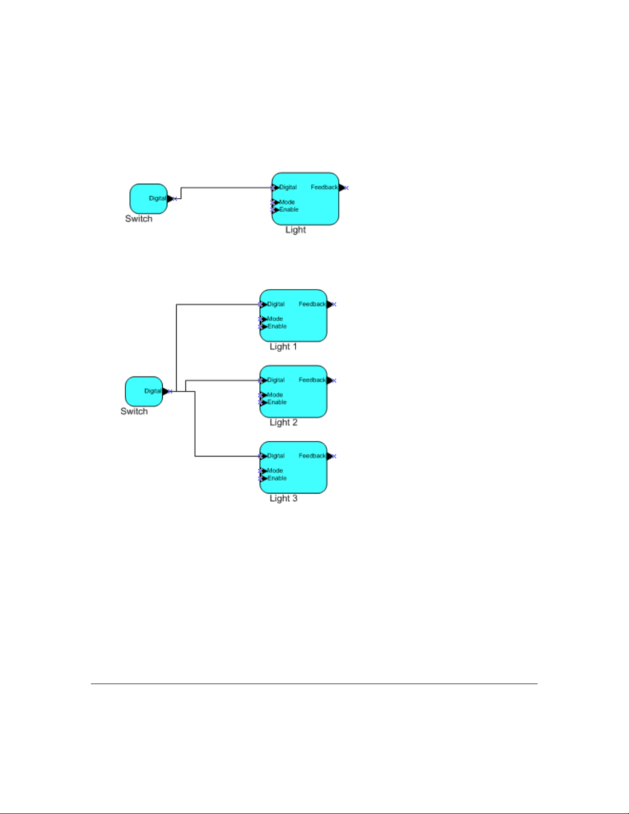
Network variables of identical type and length but opposite directions can be connected to allow the
devices to share information. For example, an application on a lighting device could have an input
network variable based on the SNVT_switch type, while an application on a dimmer-switch device
could have an output network variable of the same SNVT_switch type. A network management tool
such as the IzoT Commissioning Tool could be used to connect these two devices, allowing the switch
to control the lighting device, as shown in the following figure:
A single network variable may be connected to multiple network variables of the same type but
opposite direction. The following example shows the same s witch being used to control three lights:
The application program in a device does not need to know where input network variable values come
from or where output network variable values go. When the applic ation program has a cha nge d val ue
for an output network va riable, i t simply assi gns the ne w va lue to the out put network variabl e.
Through a process called binding that takes place during network design and installation, the device is
configured to know the logical address of the other device or group of devices in the network
expecting that network variable’s values. The device’s embedded firmware assembles and sends the
appropriate packet(s) to these destinations. Similarly, when the device receives an updated value for
an input network variable required by its application program, its firmware passes the data to the
application program. The binding process thus creates logical connections between an output network
variable in one device and an input network variable in another device or group of devices.
Connections may be thought of as virtual wires. For example, the dimmer-switch device in the
dimmer-switch-light example could be replaced with an occ upancy sensor, without making any
changes to the lightin g device.
Configuration Properties
Configuration properties define how an application device behaves by determining the manner in
which data is manipulated and when it is transmitted. Configuration properties determine the functions
IzoT Commissioning Tool User’s Guide 7
Page 24
Lamp Actuator
Mandatory network variables
Configuration properties
Optional network variables
nviLampValue
SNVT_switch
nv1
SFPTLampActuator
nvoLampValueFb
SNVT_switch
nv2
nvoEnergyCnt
SNVT_elec_kwh
nv4
nvoRunHours
SNVT_elapsed_tm
nv3
Mandatory
Optional
SCPT_location
SCPTinFbDly
SCPT_def_output
SCPTrunHrInit
SCPTrunHrAlarm
SCPTenrgyCntInit
to be performed on the values stored in the network var i ables. For example, a configuration property
may specify a minimum change that must occur on a physical input to a device before the
corresponding output network variable is updated. Like network variables, configuration properties
have types that determine the type and format of the data they contain.
Functional Blocks
Applications in devices are divided into one or more functional blocks. A functional block is a
collection of network variables and configuration properties that work together to perform a single
task. These network variables and configuration properties are called the functional block members.
For example, a digital input device could have four digital input functional blocks that contain the
configuration properties and output network variable members for each of the four hardware digital
inputs on the device. A functi onal block is an implementation of a f unct ional profile.
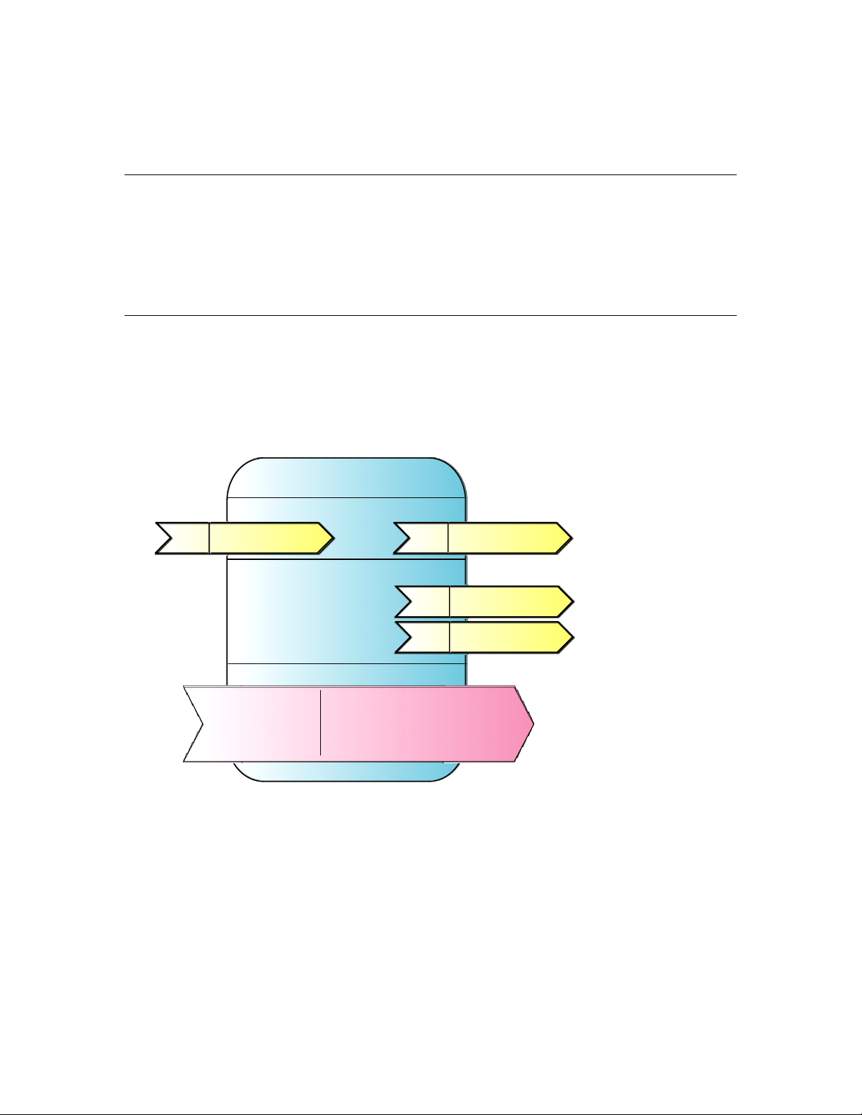
Functional Profiles
A functional profile defines mandatory and optional network variable and configuration property
members for a type of functional block. For example, the standard functional profile for a light
actuator has mandatory SNVT_switch input and output network variabl es, optiona l
SNVT_elapsed_tm and SNVT_elec_kwh output network variables, and a number of optional
configuration properties. The following diagram illustrates the components of the standard light
actuator functional profile:
When a functional block is created from a functional profile, the application designer can determine
which of the optional configuration properties and network variables to implement.
Standard Network Variable and Configurati on P rope r ty Types
Every network variable and configuration pr operty has a type, which determines the content and
structure of the data. To enable devices from different manufacturers to interoperate, the following
standard types are defined:
• Standard Network Variable Types (SNVTs, pronounced snivits). SNVTs cont ain many common
operational data types. For example, SNVT_temp_p is a network variable type for network
variables containing temperature as a fixed-point number.
8 Introduction
Page 25

• Standard Configuration Property Types (SCPTs, pronounced skipits). SCPTs contain many
common configuration data types. For example, SCPT_location is a configuration property type for
configuration properties containing the device location as a text string.
See types.lonmark.org for a list and description of all SNVTs and SCPTs.
User-defined Standard Network Variable and Configuration Property Types
Applications may use manufacturer-defined non-standard types—user network variable types
(UNVTs) and user configuration property types (UCPTs)—which are defined in user resource files.
Device manufacturers may provide additional resource files that define these types. See the
NodeBuilder Resource Editor User’s Guide for additional information on creating or using these files.
Subsystems
Devices, routers, and functional blocks are contained in subsystems. With the IzoT Commissioning
Tool, each subsystem corresponds to one page within an OpenLNS CT drawing. S ub systems allow
you to place devices, routers, and functional blocks onto separate pages for organizational purposes.
You may also nest subsys tems in ot her subsystems, allo wing you to create a subsystem hierarchy for
large networks. For example, a network may consist of HVAC, lighting, security, and operator
subsystems. These may be further divided into subsystems for each floor, and each floor divided into
subsystems for each room.
Supernodes
Using the IzoT Commissioning Tool, you can also use subsystems to create supernodes. A supernode
is a subsystem with its own net work varia ble interface. You can use supernodes to organize groups of
devices into logical units a nd to hide complex subsystem details, expo sing only the most import ant
network variables. This structure reduces errors and decreases the time required for network
engineeri ng and commissioning. A network variable interface for a supernode may contain any
network variable on any device fu nctional bl ock found within the supernode or in any of its nested
subsystems.
Visio Basics
The IzoT C ommissioning Tool is built on the Visio drawing tool to provide a r ob ust technical drawing
environment for network design. An OpenLNS CT drawing consists of one or more drawing files, and
each drawing file contains multiple subsystems that are each displayed on individual Visio pages. The
Visio documentation provides detailed descriptions of Visio commands and capabilities.
Two key Visio concepts are shapes and stencils. Shapes are reusable drawing objects. A shape may
represent a simple drawing object such as a line, arc, circle, or square, or it may represent a complex
drawing object with special behavior such as OpenLNS CT SmartShapes
SmartShapes for subsys tems, application devices, functional blocks, network variables, message tags,
connections, routers, and channel s .
To simplify finding and reusing shapes, Visio defines a special type of drawing called a stencil. A
shape contained on a stencil is called a master shape. When you drag a maste r shape fro m a stencil to
one of your drawing pages, Visio automatically makes a copy of the master shape on your drawing a nd
leaves the master shape unchanged on the stencil.
You can create custom master shapes and stencils for any set of OpenLNS CT SmartShapes. For
example, the IzoT Commissioning Tool includes custom master SmartShapes and a custom stencil for
SmartServer devices and functional blocks. Yo u may wish to create your own custom master
SmartShapes and stencils to speed up network design. See Chapter 12, Creating and Using Custom
OpenLNS CT Master SmartShapes, for more information.
. OpenLNS includes
To simplify access to your most commonly used stencils and drawing options, Visio defines another
type of drawing called a template. Templates are drawings that may be used as the starting point when
IzoT Commissioning Tool User’s Guide 9
Page 26

you create a new drawing. The IzoT Commissioning Tool includes a L
ONWORKS template that is used
automatically when you create an OpenLNS CT drawing. If you wish, you can create your own
custom OpenLNS CT template and select it as the default template in the OpenLNS CT Design
Manager. See New Network Options in C hapter 3 for more information on selecting the default
drawing template.
10 Introduction
Page 27

IzoT Commissioning Tool User’s Guide 11
Page 28

2
Installing and Activating
the IzoT Commissioning Tool
This chapter describes how to order the IzoT Commissioning Tool, install the various
software and components included in your copy of the IzoT Commissioning Tool, and
how to activate the IzoT Commissioning Tool.
12 Installing and Activating the IzoT Commissioning Tool
Page 29

Echelon
IzoT Commissioning Tool Product
38000-400
OpenLNS Commissioning Tool Professional Edition (DVD)
38010-400
OpenLNS Commissioning Tool P rofessional Edition Without Visio (DVD)
38050-400
OpenLNS Commissioning Tool P rofessional Edition Activation Key
38060-400
OpenLNS Commissioning Tool Profe ssi ona l Edition Without Visio Activation Key
38100-400
OpenLNS Commissioning Tool Sta ndard Edition (DVD)
38150-400
OpenLNS Commissioning Tool Standard Edition Activation Key
38160-400
OpenLNS Commissioning Tool Standard Edition Without Visio Activation Key
38300-400
OpenLNS Commissioning T ool Trial Edition Without Visio Activation Key
Ordering the IzoT Commissioning Tool
You can order the IzoT Commissioning Tool directly from Echelon, from an Echelon distributor, or
from the Echelon store at store.echelon.com. If you order from the Echelon store, make sure you
provide a valid e-mail address when you order the IzoT Commissioning Tool products. Once you
complete your order, Echelon will send you an e-mail message to the provide d e-mail address with the
activation key for your IzoT Commissioning Tool products. You can order the following p roducts
from the Echelon store:
Part No.
You can download your IzoT Commissioning Tool products from the Echelon Web site at
www.echelon.com/openlns, and then install and activate them as described in the next section.
Installing and Activating the IzoT Commissioning Tool
You can install a licensed copy of the IzoT Commissioning Tool on up to two computers, a primary
and a secondary computer, provided that the following requirements are met: only the IzoT
Commissioning Tool user on the primary computer can use the copy of the IzoT Commissioning Tool
on the secondary computer and the IzoT Commissioning Tool soft wa re may only be used on one
computer at a time. See the OpenLNS CT Software License Agreement in Appendix C for more
information. To begin your installation, follow these steps:
1. If you are installing a version of the IzoT Commissioning Tool that does not include Visio, you
must separately purchase and install the 32-bit version of Visio 2010 or Visio 2003 before
installing the IzoT Commissioning Tool software.
2. If you do not have an Echelon download account, create one on the Echelon Web site at
www.echelon.com/support/downloads/accounts. Your account will enable you to d ownload
OpenLNS software from the Echelon Web site; make activating and managing li censes for
multiple Echelon products easier; enable you to return, transfer, and recover licenses; and help you
receive technical support from Echelon faster.
3. Download the IzoT Commissioning Tool from the Echelon Web site and run the
OpenLNSCTSetup.exe file, or insert the OpenLNS CT DVD into your DVD-ROM drive.
If you are installing the IzoT Commissioning Tool from a DVD and the IzoT Commissioning Tool
setup application does not launch immediately, click Start on the taskbar and then and click Run.
Browse to the OpenLNSCTSetup application on the OpenLNS CT DVD and click Open. The
Select Components dialog box opens.
IzoT Commissioning Tool User’s Guide 13
Page 30
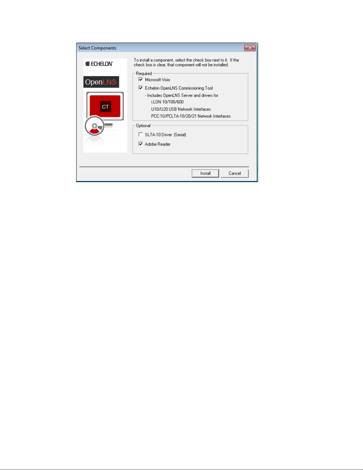
4. Select the components that you wish to install by selecting the appropriate check boxes on the
Select Components dialog box.
• Microsoft Visio: Installs the 32-bit version of the Visio 2010 drawing tool. To install the
32-bit version of Visio 2010, your computer cannot have the 64-bit version of any Office
2010 application installed on it.
The IzoT C ommissioning Tool is not co mpatible with the 64-bit version of Visio 2010 (even
if your co mputer is usin g a 64-bit operating s ystem), and it is not compatible with any version
of Visio prior to Visio 2003. If you already have a 64-bit version of any Office 2010
application, you must uninstall it before installing the 32-bit version of Visio. You can
reinstall the 32-bit version of any 64-bit Office software that you have installed.
• Echelon OpenLNS Commissioning Tool: Installs the required components of the IzoT
Commissioning Tool. Installing the IzoT Commissioning Tool automatically installs the IzoT
Network Services Server, the OpenLNS CT XML Utility
, and the dr ivers for the following
OpenLDV 4.0-compatible network interfaces:
o Remote Network Interfaces (RNIs): SmartServer , i.LON 100 Internet Server, i.LON 600
IP-852 Router, and i.LON 10 Ethernet Adapter
o Local USB network interfaces: U10/U20 USB network interfaces.
o Local PC card network interfaces: PCC-10 and PCLTA-10, 20, and 21 PCI network
interfaces. The PCC/PCLTA a nd SLTA-10 network drivers are compatible with 32-bit
versions of Windows only and are not installed on 64-bit versions of Windows.
If you are using the IzoT Commissioning Tool on an IP-852 channel, yo u will ne ed an IP
network interface card (such as Ether net or WiFi) or modem with PPP software. An IP
network interface is also required if you are using an IP-852 interface such as a SmartServer
(with IP-852 routing option), i.LON 100 Internet Server (with IP-852 routing option), or
i.LON 600 IP-852 Router. If you are using another OpenLNS interface, install the network
interface hardware and dr i ver following the instructions provided with the hardwar e.
Most network interfaces include an application that handles network interface co nfiguration.
You must perform this configuration before you can use the IzoT Commissioning Tool while
attached to a network. The application may handle host details such as IRQ assignment, and
it may also manage network parameters such as buffer counts and transceiver types.
14 Installing and Activating the IzoT Commissioning Tool
Page 31

You can use the L
ONWORKS Interfaces application in the Control P anel to define, co n figure,
and test RNIs, IP-852 network interfaces, USB 10/20 network interfaces, and PCC/PCLTA
network interfaces.
• SLTA-10 Driver (Serial): Installs the network driver for the SLTA-10 serial network
interface. Click this check box if yo u are using an SLTA-10 serial adapter as your network
interface. This option is not available on 64-bit versions of Windows.
• Adobe Reader: Installs Adobe Reader 9.2, which is a free program that allows you to read
Adobe Acrobat portable document files (.pdf extension). Many of the L
ONMARK reference
documents are exclusively in PDF format. You can clear this check box if you already have a
PDF reader application.
5. Click Install. If you are upgra ding from the LonMaker I ntegration Tool, a message opens
informing you that installing OpenLNS will remove any version of the LonMaker tool on your
computer.
6. Click Yes to continue installingIzoT Commissioning Tool.The installation program installs the
selected components sequentially, prompting you for required reboots.
7. During the installation, the following dialog opens, displaying the curre nt progress of the
OpenLNS CT setup:
IzoT Commissioning Tool User’s Guide 15
Page 32

If you selected the Visio component in the Select Components window, the Microsoft Visio setup
wizard opens. Follow the instructions in the installation pr ogram to complete the Visio setup .
8. Install IzoT Commissioning Tool fo llowing these steps:
a. The IzoT C ommissioning Tool setup program begins automatically with the Welcome
window opening.
b. Click Next. The License Agreement window opens.
16 Installing and Activating the IzoT Commissioning Tool
Page 33

c. Read the license agreement and click Yes if you agree wit h the terms. The Customer
Informatio n wi ndow opens.
d. Enter your name, organization, and the IzoT Commissioning Tool activation key in the
appropriate fields. The name and organization may be entered automatically based on the
user curre ntly logged o n and whethe r other Echelon products are installed on your compute r.
If you renewed your annual ma i ntenance and you are ins t alling yo ur upgrade on the same
computer as your original OpenLNS CT software, your ac tivation key is automatically
displayed. If you are installing an up gra d e on a different computer, you must find the
activatio n key that you saved from your original version of OpenLNS CT
Under Echelon Account, enter the user name (e-mail address) and password you created for
your Echelon download account (see step 2 if you do not have an Echelon download account).
Click Next.
IzoT Commissioning Tool User’s Guide 17
Page 34

e. If your computer is connected to the Internet, the IzoT Commissioning Tool installer c onnects
to the Echelon License Server, the License Server issues activation licenses for OpenLNS
Server and IzoT Commissioning Tool, and the installer stores the licenses on your computer.
If your computer is not attached to the Internet, you can use the Echelon License Wizard to
manually activate IzoT Commissioning Tool via e-mail or phone after installin g the software
(e-mail is recommended). See the next section, Manually Activating IzoT Commissioning
Tool, for more information.
f. If the Destination Locatio n window opens, choose a L
ONWORKS folder in which you want the
IzoT Commissioning Tool software installed, and then click Next. The IzoT Commiss ioning
Tool software will be installed in an IzoT Commissioning Tool folder below the L
ONWORKS
folder that you specify. If you previously installed other Echelon software on this computer,
use the same L
The default L
ONWORKS folder.
ONWORKS folder is C:\Program Files\LonWorks (on a 32-bit version of
Windows) or C:\Program Files (x86)\LonWorks (on a 64-bit version of Windows). If you
previously installed other Ech e lon software on this computer, the last L
ONWORKS folder that
you selected will be displayed as the de fault, and you cannot change this value.
g. The Ready to Install window opens. Click Install to begin the IzoT Commissioning Tool
installation.
h. If you need to reboot your computer, a window will appear prompting you to select to reboot
your computer now or later. After IzoT Commissioning Tool installation and any required
reboots have been completed, a window will appear, stating that IzoT Commissioning Tool
has been installed successfully and providing you with the option to view the Re adMe file.
The ReadMe file contains information that is not included in this user’s guide.
18 Installing and Activating the IzoT Commissioning Tool
Page 35

i. Click Finish. The ReadMe file opens if the Show the R e adme File check box was selected.
When you finish reading the ReadMe file, close the window.
j. A confirmation dialog opens stating that the selected components have been installed . Click
OK.
Note: Do not uninstall any of the following applications and components that are used by
OpenLNS CT: OpenLNS Server, OpenLNS XML Utility, OpenLDV, Visio, LonMark Resource
Files, Multi-Port Router 50, and the IP-852 Configuration Server. Uninstalling any of these
applications and components will cause IzoT Commissioning Tool to stop running.
9. If your computer was not attached to the Internet when you were installing OpenLNS CT, proceed
to the next section to manually activate your software. IzoT Commissioning ToolIzoT
Commissioning Tool will not run until it is activated.
IzoT Commissioning Tool User’s Guide 19
Page 36

Manually Activating IzoT Commissioning Tool
If your computer was not attached to the Internet when you installed Iz oT Commissioning Tool,
you can use the Echelon License Wizard to activate OpenLNS Server and IzoT Commissioning
Tool after you complete the software installation. You can activate your software via the Internet
if your computer is now online, or you can activate your software via e-mail or phone if your
computer is still offline. To use the License Wizard to activate your IzoT Commissioning Tool
software, follow t he se ste ps:
1. Open the Echelon License Wizard. Click Start, click Programs, point to Echelon License
Wizard, and then cli ck License Wizard. The Echelon License Wizard opens. Click Next.
2. The Step 1: What would you like to do? dialog opens.
20 Installing and Activating the IzoT Commissioning Tool
Page 37

3. To activate your IzoT Commissioning Tool software using the over the Internet or via e-mail,
click Activate Product Licenses and then cli ck Next.
To activate over the phone, click Show Advanced Tasks, Upgrade a Product License over the
Phone, and then follow the instructions in the License Wizard. If your computer is offline,
activate via e-mail if you have e-mail access because activating over the phone requires manually
entering ma ny lengthy a lpha-numeric strings.
4. If your computer is online, the Step 2: Wh at is Your Account Information dialog opens.
Complete the following steps to activate your software (if your computer is still offline, proceed to
step 5):
a. Enter your account information and/or your IzoT Commissioning Tool activation key, and
then click Next.
b. The Step 3: Which License Would You Like to A ctivate? dialog opens.
c. Select Activate from the Action list for both OpenLNS Server and IzoT Commissioning
Tool, and then click Next.
d. The Step 4: Status dialog opens, and the License Wizard activates your licenses.
e. Click Exit to close the License W izard.
5. If your computer is still offline, the Step 2: Which Product Would You Like to Get a License
For dialog opens.
6. Enter your IzoT Commissioning Tool activation key in the Enter Your Activation Key box and
then click List Products. The License Wizard lists your OpenLNS Server and IzoT
Commissioning Tool products. Select Activate from the Action list for both OpenLNS Server
and IzoT Commissioning Tool, and then click Next.
IzoT Commissioning Tool User’s Guide 21
Page 38

7. The Step 3: Where Would You Like to Save Your License Requests? dialog opens.
8. In the Request File Name property, enter a full path where a license request file (.elwrq
extension) is to be saved, or click Browse, specify the directory where the license request file is to
be saved, and then enter a name for the file.
Under Authentication Details, ent er the Echel on ID (e-mail address) and Password you created
for your Eche l on downlo ad account (see step 2 if you do not have an Echelon download account).
The Activation Key box displays the 25-character alphanumeric string for the Echelon product to
be activated. Do not modify this property.
Click Next.
9. The Status dialog opens. The License Wizard confirms the creation of the license request file.
22 Installing and Activating the IzoT Commissioning Tool
Page 39

10. Click Send Request to Echelon to e-mail the license request file to Echelon at
activation@echelon.com. Eche l on will send you an e-mail message with a license response
(.elwrs extension) file. Fo r faster activation, copy the lic ense request file to an Internet-connected
computer with the License Wizard installed on it and importing it into the License Wizard. The
License Wizard creates the license response file, which you can then copy to the original
computer.
11. Import the license response (.elwrs extension) file into the License Wizard and activate your
OpenLNS Server and IzoT Commissioning Tool licenses follo wing these steps:
a. Start the Echelon License Wizard.
b. In the Task Selection dialog, click the Show Advanced Topics link, and then click the
Process a License Response File Obtained from Echelon option.
IzoT Commissioning Tool User’s Guide 23
Page 40

c. The Import License Request or Response File dialog opens. In the File Name property,
enter the full path of the license response file (.elwrs extension), or click Browse and then
select the file. Click Next.
d. The Check License Response File dialog opens. Confirm that the Echelon product licenses
in the license response file are the ones you want to activate. Click Next. The License Server
installs and activates the licenses in the license response file.
e. The Status dialog opens and confirms that the OpenLNS Server and IzoT Commissioning
Tool licenses have been successfully activated.
24 Installing and Activating the IzoT Commissioning Tool
Page 41

12. Click Exit to close the License W izard .
IzoT Commissioning Tool User’s Guide 25
Page 42

3
Getting Started
This chapter describes how to plan and create IzoT Commissioning Tool network
designs. It describes how to use the IzoT Commissioning Tool Design Manager to
create, open, and manage IzoT Commissioning Tool network designs, and it explains
how to set up a network interface that enables the IzoT Commissioning Tool to
communicate with the network. It summarizes the different IzoT Commissioning
Tool client types, and it explains how to use IzoT Commissioning Tool remotely, and
how to create and use user profiles.
26 Installing and Activating the IzoT Commissioning Tool
Page 43

Design Overview
To prepare to design an IzoT Commissioning Tool network, fo llow these st eps:
1. Define network requir ements and organization.
2. Select a network installation scenario.
3. Determine user permissions for viewing and changing the network.
4. Optimize network performance.
Defining Network Requirements and Organization
You can define your network’s requirements by evaluati ng which devices (sensors, actuators, and
controllers) are needed to achieve the desired network functions and how the devices will be integrated
into the network. For example, your network may need a simple fan coil unit, which could require a
fan start/stop relay, a cooling coil valve, and a supply air temperature sensor. You could use digital
output, analog output, and analog input devices, respectively, to integrate these devices (the analog
output module could also includes a PID controller you can use to control the fan co il unit).
Once you de fine the net work requirements, yo u can figure out how to organize the network in IzoT
Commissioning Tool. You can help organize the network by answering the following questions:
• How will devices and functional blocks be grouped within subsystems?
• Which functional blocks are needed for the devices to accomplish desired tasks?
• How do functional blocks need to be configured and connected to correctly interpret values from
sensors, perform any necessary calculations, and drive actuators?
Selecting a Network Installat ion Sc en ar io
You can design your entire network without commissioni ng any devices until after your design is
complete, or you can design your network and commission devices at the same time. These two
approaches are called installation scenarios. The first network installation scenario is called the
engineered system and the seco nd is the ad-hoc system. You can use both scenarios wit hin a single
system, or you can use either exclusively. The best scenario for a given network de pends on many
factors including the skill level o f the i nstaller, desired flexibility for the ne twork, and the end-user
requirements.
Engineered System Scenario
The engineered system scenario allows you to desi gn the network without having acces s t o the
physical devices
First, you de s i gn the network offsite using IzoT Commissioning Tool. You drag IzoT Commissioning
Tool SmartShapes representing devices, routers, IP-852 routers, functional blocks, and connections
from an IzoT C ommissioning Tool stencil to an OpenLNS CT drawing a nd arrange t hem on the
drawing, and into multiple subsystems if desired.
Once you are onsite and have attached an IzoT Commissioning Tool compute r to the network, you
then commission the physical devices. IzoT Commissioning Tool commissions a device by
configuring the physic al device t o match the configuration that yo u s pecified i n the OpenLNS CT
drawing.
Engineered systems must often be modified during on-site installation due to differences between
as-drawn plans and the physical network. IzoT Commissioning Tool supports on-site changes to the
engineered system to a llow for these changes during commissioning.
The advantage of the engineered system scenario is that it makes network installation quick, easy, and
error-free because most of the time-consuming data entry and processing is done offsite during the
design phase. This scenario is often used for building and industrial automation systems, in which the
original design closely matche s the actual installation.
IzoT Commissioning Tool User’s Guide 27
Page 44

Ad-Hoc System Scenario
The ad-hoc system scenario allows you to design a nd install the network onsite. In this scenari o, IzoT
Commissioning Tool loads the network configuration information into each device as you define
devices, configurations, and connections. This is different from the engineered system sce nario in that
information is incrementally loaded to the physical devices.
The advantage of the ad-hoc system scenario is its flexibility, a s the in stalle r can make decisions
onsite. It is most appropriate for simpler systems in which the details of the system to be installed are
not known prior to commissioning.
The disadvantages of the ad-hoc system scenario are that it’s slower for large systems and requires the
same person to do both the network design and installation.
Determining User Permiss ions
When you create an IzoT Commissioning Tool network design, IzoT Commissioning Tool does not
assign any security to the network drawing. It defaults to one user—the administrator of the IzoT
Commissioning Tool drawing. While this default is permissible if one person is performing the
network inst allation in a secure e nvi ronment, it may not be suitable for multi-user or insecure
environments. In these environments, you need to create and manage user profiles to control access to
your IzoT Commissioning Tool network design. This will prevent any unauthorized changes to your
IzoT Commissioning Tool network design and enable you to better manage the installation or repair of
a system.
User profiles allow you to create access controls for a network drawing and its subsystems and set
privileges for actions that can be performed on IzoT Commissioning Tool objects. For example, you
could have a scenario in which a system integrator has access to the entire networ k and can add o r
change application devices and routers, while the installers can also access the entire network, but only
can commission the application devices and routers.
You might use a different scenario if you are working with multiple s ystem integrators who are all
supplying devices for your network. In this case, you can give each integrator access to their
subsystem o nly but allow them to freely change the subsystem drawin g and commiss i on devices. This
prevents one integrator from accidentally modifying a drawing created by another integrator.
By default, user profiles are not enabled for new networks. To enable user profiles, you must first
assign an Administrator password and create new user profiles as described in User Profiles. The
Administrator can create, modify, and delete user profiles.
Once you logon as a user other than the Administrator, you can still create new user profiles, as
described in Creating a New User Profile, and you can change your password as des cribed in
Changing Passwords.
For information on using user profiles with IzoT Commissioning Tool remotely, see Using IzoT
Commissioning Tool Remotely with User Profiles.
Optimizing IzoT Commissioning Tool Network Performance
Many factors affect the performance of an IzoT Commissioning Tool network design. The following
are guidelines for several aspects of your IzoT Commissioning Tool network design t hat can help
optimize network performance— especially for large networks.
Drawing Files
A single drawing file should not be larger than 3MB, or consist of more than 20 typical pages or 10
complex pages. If you are creating a network exceeding these guidelines, desig n the subsystems in
multiple drawing files. For optimum performance, devices and their associated functional blocks
should be contained within the same drawing file, as should all members of the same connection.
28 Getting Started
Page 45

When designing multiple drawing files, organize the individual drawing files as subsystems withi n the
top-level drawing file, and limit the top-level drawing to con tain only those subsystems. This
minimizes the number of drawing files that must be opened as you descend the subsystem hierarchy.
Avoid deep sub s yste m hier a rchies with long sub s ys tem names that re sults in long subsystem paths.
Subsystem paths may be stored in devices to help the network recovery process if you lose the network
database, but devices have limited memory available to store the network path. Furthermore,
visualization tools such as Wond erware’s InTouch
exceeded with long sub system pa ths.
®
have limits to item name lengths that can be
Network Changes
To improve network per formance when making n umerous network changes at one time, set IzoT
Commissioning Tool to OffNet. This will allow you to make the changes quickly, as the changes will
be saved in the OpenLNS network database instead of being sent to the physical devices. Whe n yo u
finish making the chan ges, set IzoT Commissioning Tool to OnNet and the changes are propagated to
the physical devices.
Connections
If you will be making changes to a subsystem, limit the number of connections monitored by IzoT
Commissioning Tool to less than five per subsystem. Having more than five monitored connec tions in
a subsystem will increase the time required to perform certain network management operations.
Alternatively, you can turn off a ll monitoring while making changes by right-clicking a clear space in
the subsystem page and clicking Enable Monitoring if it is curr e ntly set. You can turn monitoring on
again after making the changes.
If you are using an OpenLNS application that does not support monitor sets (groups of data points that
IzoT Commissioning Tool uses to monitor and control ne twork variables) and you are maki ng many
bound connections to the OpenLNS application, make the bound connections persistent. This will
improve network performance. Conversely, non-persistent bound connections, which can be created in
an IzoT Commissioning Tool net wo rk with OpenLNS applications other than IzoT Commissioning
Tool, can significantly increase the time required to open and close an OpenLNS CT drawing.
OpenLNS tools that support monitor sets, such as IzoT Commissioning Tool, enable monitoring of
monitor points to be setup quickly once an IzoT Commissioning Tool network is opened. This is
because points in monitor sets are always persistent. IzoT Commissioning Tool automatically creates
monitor sets for connection monitoring when monitoring is enabled on an IzoT Commissioning Tool
network. To enable monitoring, right-click a clear space in the subsystem page and clicking Enable
Monitoring if it is not currently set. For more information on monitor sets, see the OpenLNS
Programmer’s Guide.
Sharing the OpenLNS Interface with the LNS DDE Server
If the LNS DDE Server and IzoT Commissioning Tool are running concurrently and sharing the same
OpenLNS network interface, limit the polling rate of the LNS DDE server to 10 polls per second on a
ONWORKS channel. Ha ving the LNS DDE Server polling above this rate will degrade network
L
performance. By default, the LNS DDE server polls active network variables every 1 second, so more
than 10 active network variables running at the default poll interval can impact network performance.
You will see similar performance degradation if you have any other OpenLNS monitoring application
sharing the OpenLNS network interface with IzoT Commissioning Tool, or if you are using c onnection
monitoring in IzoT Commissioning Tool.
If you will be making numerous network changes, either disable the LNS DDE Server and any other
OpenLNS monitoring applications, or reduce the polling rate to a maximum of 10 polls per second
while you ar e making changes.
IzoT Commissioning Tool User’s Guide 29
Page 46

Functional Blocks
If you have a large network with many unconnected network variables on the functional blocks, delete
the unused network variable SmartShapes. Network variable SmartShapes add performance overhead,
yet they are not required if they are not connected. You can re-add network variable SmartShapes to a
functional block if you need to connect them later. To simplify following this g uideline, you can
create functional block master SmartShapes with your most commo nl y used ne t wor k var ia b le s. See
Creating a Functional Block Master SmartShape in Chapte r 4, Designing Networks for more
information.
Subsystems
Subsystems allow you to divide a large network into more manageable parts. For example, in a
building control network, one subsystem cou l d contain li ghting cont rols and another temperature
controls. Each subsystem is represented by a page of an OpenLNS CT drawing and by a subsyste m
SmartShape on the drawing page of its parent subsystem. You can nest subsystems li ke directories on
your computer, so the temperature control subsystem could contain other subsystems rep resenting, for
example, each floor of the building. You can also create subsystems in separate OpenLNS CT
drawings. Using this feature, you can create large networks while maximizing Visio’s performance by
limiting the number of p ages in a single drawi ng. Yo u ca n also create a separate OpenLNS CT
drawing for each user for large networks with multiple installers.
If you are creating a network that needs more subsystems than 20 typical pages or 10 complex pages,
you should divide it into two or more drawing files. For optimum performance, devices and their
associated functional blocks should be contained within the same drawing file, as should all members
of the same connection.
A supernode is a special type of subsystem SmartShape that has one or more network variable
interfaces on it. Any network variable or message tag on an y functional block in the subsystem may
be exported to the subsystem SmartShape. This does not create new network variables or message
tags, but exports the ne twork variable or message tag’s connection point one or more levels up the
subsystem hie ra rc h y. Using a supernode allows you to provide a simple interface to an arbitrarily
complex subsystem. For example, a supernode that contains lighting controls may have a network
variable interface that allows the devices contained within it to be put into emergency o verride. This
allows the integrator to easil y ide ntify the critical interfaces into the subsystem, while i gnoring those
that are typically only used internally by the subsystem.
IzoT Commissioning Tool Design Manager Overview
The IzoT Commissioning Tool Design Manager is an esse ntial tool for managing your IzoT
Commissioning Tool networks. With the IzoT Commissioning Tool Design Manager, you can create,
open, and delete networks; back up and restore networks to prevent against loss; and configure default
settings for new networks to speed up the network creation process.
To open the IzoT Commissioning Tool Design Manager, click Start on the taskbar, point to
Programs, point to the Echelon IzoT Commissioning Tool folder, and then click IzoT
Commissioning Tool. The IzoT Commissioning Tool Design Manager opens.
30 Getting Started
Page 47

The IzoT Commissioning Tool Design Manager consists of five tabs that let you perform the following
functions:
• General. Create, open, copy, delete, and backup/restore IzoT Commissioning Tool network
designs; start the OpenLNS Server application; and import and defragment OpenLNS network
databases.
• Options. Set a prioritized list of languages for L
• New Network Options. Configure default properties for the pages in the Network Wizard and
options to s kip the page s , and set the network components.
• IzoT Commissioning Tool Stencils. Add, remove, or modify the properties of IzoT
Commissioning Tool stencils.
• IzoT Commissioning Tool Default Options. Configure the default properties and behavior for
IzoT Commissioning Tool objects (for example, adding devices, adding functional blocks, and
backing up and synchronizing the OpenLNS database).
ONMARK resour ce files.
General
You can use the General tab in the IzoT Commissioning Tool Design Manager to create, open, copy,
delete, backup, restore IzoT Commissioning Tool network designs; start the OpenLNS Server
application so remote clients can access the OpenLNS netwo r k database; import a database and then
create a new OpenLNS CT drawing from it; and defragment OpenLNS net work databases. To us e the
General tab, enter the followi ng data in the boxes and click the following buttons:
New Network
IzoT Commissioning Tool User’s Guide 31
Page 48

Network Name
Specifies the name of the new IzoT Commissioning Tool network
Create Network
Creates and opens a new IzoT Commissioni ng Tool network design
Show all options
Displays all the pages in the Network Wizard as the network is
Existing Network
Drawing Directory
Selects a file from the folder indicated in the Drawing Base Path
Drawing Name
Selects an OpenLNS CT drawing from all the Op enLNS CT
Database Name
Selects an OpenLNS network database from all the OpenLNS
Open Network
Opens the OpenLNS CT drawing and associated OpenLNS network
Open Copy
Opens a copy of the OpenLNS CT drawing specified in the Drawing
Delete
Deletes the OpenLNS CT drawing and OpenLNS network database
design to be created. The name must be unique to all the IzoT
Commissioning Tool networks on this computer. You can enter up
to 16 characters and include embedded spaces. The name is not case
sensitive; therefore, you cannot create two networks with names that
differ only in capitalization.
The initial default network name is “Network 1”. IzoT
Commissioning Tool automatically increments the index in the
default network name so that the network names are unique for
subsequent networks you create using the default name. After you
create a network with a different name than the initial default, the
default network name will beco me the last network created with an
incremented index. For example, if you create a new network
named “Test”, the default network name will be “Test 1”. If you
create the “Test 1” network, the default network name will become
“Test 2”, and so on.
consisting of a new OpenLNS network database and a new
OpenLNS CT drawing.
opened, regardless if the Skip this Prompt option is selected for a
page in the New Network Options tab.
To create networks with one-click, clear this check box and select
the options in the New Network Options tab to skip the pa ges in the
Network Wizard.
list. To open an e xi sting IzoT Commissioning Tool network design,
select the folder containing the OpenLNS CT drawing file.
drawings contained in the selected drawing folder. Select the
OpenLNS CT drawing you want to open, delete, or backup.
network databases on this computer. Select the database you want to
defragment, delete, or backup, or from which you want to start the
OpenLNS Server. This field is not used for the Open Network,
Open Copy, and Restore operations.
database specified in the Drawing Name list. The Database Name
list is ignored by this operation.
Name list, making a copy of the OpenLNS CT drawings and the
associated OpenLNS network database. This copy is created like a
new networ k. (You will be prompted to choose a new top-level
drawing name and database path. The Database Name list is
ignored by this operation.)
specified in the Drawing Name and Database Name lists,
respectively. To delete only a drawing or a database, select <none>
32 Getting Started
in the appropriate list.
Page 49

Defragment Database
Defragments and recreates the index for the IzoT Commissioning
Start OpenLNS Server
Starts the OpenLNS Server applicatio n so that r emote client
Backup
Opens the IzoT Commissioning Tool Backup dialog, in whi c h yo u
Show all options
If this check box is selected, all of the network option windows will
Restore
Restores an OpenLNS CT drawing and OpenLNS network database
Import
Imports an OpenLNS network database (objects.dat file) into
Settings
Drawing Base Path
Determines the directory that will be used by the Drawing
Add
Lets you select a drawing folder to add to the Drawing Base Path
Exit
Closes the IzoT Commissioning Tool Design Manager. This does
Tool database specified in the Database Name list. This can reduce
the size of and decrease the access time to a network database that
has grown i n s ize because of many changes. Backup the database
before de fragmenting it in the event an error occurs during the
defragmentation process.
computers can access the OpenLNS network database.
can back up the network database specified in the Database Name
lists and all of associated drawing files.
See Manually Backing Up an IzoT Commissioning Tool Network in
Chapter 7, Maintaining Networks, for more information on how to
use the IzoT Commissioning Tool Backup dialog. See
Backup/Restore Options in Appendix A for the default backup
options you can set.
be presented as the network is opened regardless if the Skip this
Prompt option had been previously selected.
from an IzoT C ommissioning Tool backup file. See Restoring an
IzoT Commissioning Tool Network in Chapter 7, Maintaining
Networks, for more information. See Backup/Restore Options in
Appendix A for the default restore options you can set.
OpenLNS so that it opens in the Database Name box. The imported
database may have an OpenLNS CT drawing associated with it.
Select the folder containing the OpenLNS network database you
want to import. If the database does not have an OpenLNS CT
drawing associated with it, you can then click Create Drawing to
create an OpenLNS CT drawing based on the imported database.
Directory list. All of the folders in this directory will be listed in the
Drawing Directory list. You can browse through the folders to find
the desired path or enter the pathname.
list.
not close Visio or any open networks.
To automatically exit the Design Manager after opening an
OpenLNS CT drawing, c lick the Options tab in the IzoT
Commissioning Tool Design Manager and select the Exit Design
Manager After Launching Visio check box.
Options
The IzoT Commissioning Tool Design Manager’s Options tab allows you to set a prior itiz e d list of
languages for L
IzoT Commissioning Tool User’s Guide 33
ONMARK resource files. This list i s then applied to all new networks you cr e a te .
Page 50

Languages
Lists the languages in the order they will be searched for device
Move Up
Moves the selected language up one position in the list.
Move Down
Moves the selected language down one position in the list.
When IzoT Commissioning Tool displays documentation for selected devices, functional blocks, and
network variables, it uses the definitions contained in L
ONMARK resourc e file information in different languages by specifying a prioritiz e d list of languages
L
ONMARK resource files in IzoT Commissioning Tool.
for L
ONMARK resource files. You can display the
You can set the resource file language for a specific network while in IzoT Commissioning Tool by
clicking Add-ins, clicking IzoT Commissioning Tool, clicking LonWorks Network, clicking
Network Properties, and then click ing the Resource File Language tab.
The IzoT Commissioning Tool Design Manager’s Options tab contains the following options:
ONMARK
Set L
Resource Files
Languages
Allows available language-specific L
added, removed, or reordered in the languages list. When searching
for a resource definition such as an NV field name, IzoT
ONMARK resource files to be
Commissioning Tool searches the first language file in the list for the
device info rmation, then the sec ond language file in the list, and so on
until it finds the information for the sp ecified device. If no match is
found and the device information is found in the corresponding U.S.
English file, the English text will be used to display the information.
U.S. English is t he default language and cannot be removed from the
list. The language-specific L
ONMARK resource files add e d to the list
must be installed and availabl e to IzoT Commissioning Tool. Usually
they will have been installed if availab le a nd you click Add to add
them to the list.
information.
34 Getting Started
Page 51

Remove
Removes the selected language from the list.
Add
Adds a language to the end of the list.
Exit Design Manager
Selecting this option automati c a lly closes the IzoT Commissioning
Network Interface
Network Attached
Select this check box to specify that the IzoT Commissioning Tool
Network Interface
Select the OpenLNS network interface to be used for communication
after Launching Visio
Tool Design Manager a ft er launching Visio.
New Network Options
You can use the New Network Options tab to set the default net work interface, automatically register
plug-ins, set the default network management mode, and set the default drawing template. The
properties you set are then applied to each new network you create.
You can also select options to have IzoT Commissioning Tool skip the pages in the Network Wiz ard
when opening a network. If you additionally clear the Show all Options c hec k bo x unde r the New
Network box in the General tab, you can create new networks with one-click, skipping all the pages
in the Network Wizard .
The IzoT Commissioning Tool Design Manager’s New Network Options tab contain s the following
options:
computer will be attached to the physical network so that IzoT
Commissioning Tool can communicate with the physical devices.
Clear this check box if you the IzoT Commissioning Tool computer
will not be attached to the network. This check box is cleared by
default.
Name
IzoT Commissioning Tool User’s Guide 35
between the IzoT Commissioning Tool computer and the physical
Page 52

network. This option is only available if you selected the Network
Skip Network Interface
Skips the ne twork interface page i n the Network Wizard when you
Plug-Ins
Register Plug-Ins
Select this check box to register all enabled plug-ins when you create
Skip Plug-ins Options
Skips the plug-in registration page in the Network Wizard when you
User Logon
Skip Logon Options
Skips the user logon page in the Network Wizard when you open an
Management Mode
Select when changes made in your OpenLNS CT drawing are
OnNet
Changes to the OpenLNS CT drawing are sent immediately to the
OffNet
Changes to the OpenLNS CT drawing are saved in t he OpenLNS
Skip Mode Options
Skips the ma nagement mode page in the Network Wizard when you
Network Components
Drawing Template
Lists the templates available fo r new IzoT Commissio nin g T oo l
Attached check box.
Options Page
Page
Page
create a new IzoT Commissioning Tool network.
a new IzoT Commissioning Tool network.
create a new IzoT Commissioning Tool network.
IzoT Commissioning Tool network.
transmitted to the physical device s on the network.
physical devices on the network. Select OnNet if you are
commissio ning an engineered system or if you are working on any
phase of an ad-hoc system.
network database, but are not propagated to physical devices until
IzoT Commissioning Tool is placed OnNet. Select OffNet if you are
designing an engineered system.
Once you have commissioned devices with IzoT Commissioning
Tool OnNet, you can make real-time changes to network variables
when IzoT Commissioning Tool is OffNet.
You can read and make changes to configuration properties while
IzoT Commissioning Tool is OffNet, but changes will not be
propagated until you set IzoT Commissioning Tool OnNet or you
manually propagate them (by right-clickin g a device, pointing to
Commissioning, and selec ting Propagate CP Values to Device on
the shortcut men u) .
Page
create a new IzoT Commissioning Tool network.
networks. The template is an empty Ope nLNS CT d ra wing tha t
specifies a default drawing background, styles, stencils, and other
IzoT Commissioning Tool settings. You can select from the
following three default IzoT Commissioning Tool templates that are
listed:
• LONWORKS is the initial default template used for new
networks. It uses U.S. measurement units.
ONDEMO is the template used to cr e a te a demonstration
• L
network. In a demo network, you can only create a maximum
of five application devices .
ONWORKSMetric is a template that uses SI measurement
• L
units for d rawing pages .
36 Getting Started
Page 53

Custom IzoT Commissio ning Tool templates installed in the
Root Subsystem Name
Specifies the top-level subsystem name, which opens on the title
Initial Channel Name
Specifies the name of the initial channel that is attached to the
Edit
Click the name of an IzoT Commissioning Tool stencil you wish to
Commissioning Tool stencil file. Conversely, you can change the
template directory are also liste d.
block on the top-center of the first page of each new OpenLNS CT
drawing. Subsystem names may be up to 85 characters, may include
embedded spaces, but may not include the period, backslash, colon,
forward slash, or double quote characters. Subsystem names are case
sensitive. The default top-level subsystem name i s “Subsystem 1”.
OpenLNS Network Interface in each new network drawing.
Channel na mes may be up to 85 characters, may include embedded
spaces, but may not include the period, backslash, colon, forward
slash, or double quote characters. Channel names are case sensitive.
The default root channel name is “Channel 1”.
IzoT Commissioning Tool Stencils
The IzoT Commissioning Tool Design Manager’s IzoT Commissioning Tool Stencils tab lists the
IzoT Commissioning Tool stencils that are initia lly available in the L
or creating a net work drawi ng. It allows you to add, remove, or modify the properties of IzoT
Commissioning Tool stencils.
ONWORKS template upon opening
The IzoT Commissioning Tool Stencils tab contains the following options:
modify and then click Edit. The Edit Stencil Properties dialog
opens. You can change the name of the IzoT Commissioning Tool
version or modify the description associated with an IzoT
IzoT Commissioning Tool User’s Guide 37
Page 54

stencil file associated with the IzoT Commissioning Tool ver sion or
Add
Click Add to open the Add New Stencil dialog. Click Browse, select
Delete
Click the name of an IzoT Commissioning Tool stencil you want to
description of a stencil file.
a Visio stencils (.vss) file from C:\Program
Files\LonWorks\LonMaker\Visio (32-bit system), C:\Program
Files (x86)\LonWorks\LonMaker\Visio (64-bit system), or from
another folder in your computer, and then click Open. You can then
enter the IzoT Commissioning Tool version and a description of the
selected Visio stencil. There is no limit on the number of characters,
and you can include embedded spaces , per iods , backsl ashe s , colons,
forward slashes, and double quotes . When you are done, click OK.
remove from the list and then click Delete (the stencil file is not
deleted).
IzoT Commissioning Tool Default Options
You can use the IzoT Commissioning Tool Default Options tab to set the IzoT Commissioning Tool
default properties for the new networks you create. This tab contains a list of IzoT Commissioning
Tool options categories such as options for configuration properties, devices, func t ional blo cks and for
backing up and synchronizing the IzoT Commissioning Tool network database. The default options
you set will be applied to each new IzoT Commissioning Tool network you create. Once you create a
new networ k, you can change any o f t he default options in the OpenLNS CT dra wing by clicking
Add-ins, clicking IzoT Commissioning Tool, and then clicking IzoT Commissioning Tool Options.
Click Restore Defaults to reset the options and values in the currently displayed options category to
their defaults.
You can set the default options for new networks in the followi ng options categories:
38 Getting Started
Page 55

• Backup/Restore
• Configuration Propertie s
• Device
• Functional Blocks
• General
• Naming Optio ns
• Network Explorer
• NV Browser/Monitoring
• OpenLNS Events
• IzoT Commissioning Tool Font
• Recovery
• Service Pin
• SmartShape ToolTips
• Synchronization
• Warnings
Appendix A details the defaults you can set under each network properties options category.
Setting Up a Network Interface
To attach your IzoT Commissioning Tool computer to a LONWORKS network, you must define and
configure an OpenLDV 4.0-compatible network interface or an IP-852 network interface before
starting IzoT Commissioning Tool. Networ k interfaces include the following:
• RNIs: SmartServer, i.LON 100 Internet Server, i.LON 600 IP-852 Router, and i.LON 10 Ethernet
Adapter.
• IP-852 network interfaces: SmartServer (with IP-852 routing option), i.LON 100 Internet Server
(with IP-852 routing option), and i.LON 600 IP-852 Router.
• Local USB network interfaces: U10/U20 USB network interfaces.
• Local PC card network interfaces: PCC-10 and PCLTA-10, 20, and 21 PCI network interfaces
(32-bit versions of Windows only).
• Serial network interface: SLTA-10 serial interface (32-bit versions of Windows only).
You can use the L
these OpenLDV 4.0 network interfaces.
ONWORKS Interfaces application in the Control Panel to define, configure, and test
Optimizing Network Interface Performance
To optimize the performance of IzoT Commissioning Tool when your IzoT Commissioning To ol
computer is attached to a L
(RNI, U10/U20 USB network interface, IP-852 network interface, or other network interface with a
Layer 2 MIP), if available . If you are using a PL-20 power line cha nnel or anot her slow channel, you
can use a legacy interface to limit network overhead (a high p er fo rma nce ne t wor k inte r fac e may
saturate the channel).
ONWORKS network, us e an OpenLNS high performance network interface
Using an IP-852 Network Interface
You can use an IP-852 channel to implement a LONWORKS co ntrol network over an IP network and
integrate multiple native L
channel as a backbone. If you are attaching your IzoT Commissioning Tool computer to an IP-852
channel, you can set up an IP-852 interface and create the IP-852 channel following these steps:
ONWORKS networks int o one large ne twork that uses a high-speed IP-852
1. Ensure that all of your IP-852 devices (for example, the OpenLNS Server computer, on e or more
IzoT Commissioning Tool computers, and one or more IP-852 routers) all have static IP addresses
IzoT Commissioning Tool User’s Guide 39
Page 56

or have dynamic IP addresses that do not change. A static IP address is an address that is not
dynamically assigned by a DHCP server.
2. Create an IP-852 interface on each computer that is to be connected to the IP-852 channel. This
may include the OpenLNS Server computer and one or more IzoT Commissioning Tool
computers. To create an IP-852 interface, follow these steps on each of the computers:
a. Open the L
ONWORKS Interfaces application in the Control P a nel.
b. Click the IP-852 tab.
c. Click Interface, point to Add, and t hen either clic k IP-852 Interface or click New Interface
and then click IP-852 in the Select Interface Type dialog.
d. The Add Network Interface Wizard dialog opens.
e. Specify the name of the new IP-852 network interface; the IP address, port, and channel
timing parameters; and authentication para meters. Click OK.
For more information on creating IP-852 network interfaces, see the LONWORKS Interfaces
online help file.
3. Define the IP-852 channel and devices in the IP-852 Configuration Server. To do this, follow
these steps:
a. Click Start on the taskbar, point to Programs, point to Echelon IP-852 Configuration
Server, and then click Echelon I P-852 Configuration Server.
b. Click Channel, and t hen click New C hannel. Enter a na me for the ne w IP-852 channel.
c. Right-click the new IP-852 channel you just created and then click New Dev ice. Enter a
name for the new device.
d. Right-click the new device and then click Device Properties. Enter the IP address for the
device.
e. Repeat steps c and d for each OpenLNS Server co mputer, IzoT Commissioning Tool
computer, and IP-852 router on the IP-852 channel.
40 Getting Started
Page 57

The devices on the IP-852 channel will not be fully commissioned until you run OpenLNS
applications such as the OpenLNS Server or IzoT Commissioning Tool on each of the
OpenLNS Server or IzoT Commi ssioning Tool computers. For more information, see the
IP-852 Channel User’s Guide.
Creating and Opening IzoT Commissioning Tool Networks
An IzoT C ommissioning Tool network consists of an OpenLNS CT drawing and an OpenLNS network
database. IzoT Commis s ioning Tool provides several ways to create an IzoT Commissioning Tool
network, i ncluding the following methods:
• Create a new IzoT Commissioning Tool network design. Use this method if you are engineering a
new networ k, or if you want to redo the logical design of an existing network.
• Use an existing OpenLNS database to create an OpenLNS CT drawing. Use this method to use
IzoT Commissioning Tool with a network that was previously installed with a n OpenLNS
application other than IzoT Commissioning Tool.
• Create an IzoT Commissioning Tool ne twork design from an exis t ing physical network, which
creates a new OpenLNS network database and an OpenLNS CT drawing. This method is called
network recovery. Use this method if the network is operational and was origi nally installed with
an application not based on OpenLNS or was self-installed. You can also use this method with a
network tha t was previously installed with an OpenLNS applica tion, but does not have its original
network database. IzoT Commissioning Tool can recover a network without changing the device
applications or network configuration. See Recovering an IzoT Commissioning Tool Network in
Chapter 7, Maintaining Networks, for more information on how to use network recovery and for a
summary of the limitations of network recovery.
• Copy an exist ing IzoT Commissioning Tool network design. Use this method to create a new
network tha t is similar t o an existi ng network.
Creating an IzoT Commissioning Tool Network Design
You can create a new IzoT Commissioning Tool network design to en gineer a new ne twork or to redo
the logical design of an existing network. To create a new network design, you must use IzoT
IzoT Commissioning Tool User’s Guide 41
Page 58

Commissioning Tool as a local client (IzoT Commissioning Tool is running on the same computer as
the OpenLNS server).
To create a new IzoT Commissioning Tool network, follow these steps:
1. Click Start on the taskbar, point to Programs, point to Echelon IzoT Commissioning To ol, and
then select IzoT Commissioning Tool. The IzoT Commissioning Tool Design Manager opens.
2. Under New Network, enter the name of the network in the New Network box, or accept the
default netwo rk name.
3. Click Create Network to create the new network. Visio starts.
• When you initially start Visio 2010, a message opens informing you t hat Visio must activated.
Click OK and follow the activation instructions.
• When you initially attempt to create a network, a message opens informing you that Visio
must be launched and initialized so that it can work with IzoT Commissioning Tool.
• In addition, a warning opens as ki n g you if yo u wa nt to enab l e macr o s, which are required for
IzoT Commissioning Tool to function. Click Enable Macros. See Working with D igital
Signatures for more information.
4. If you s e lected the Show all Options check box under t he New Network box in the IzoT
Commissioning Tool Design Manager, or you cleared the check boxes for skipping the network
interface, management mode, and plug-i n options pages of the Ne twork Wizard in the New
Network Options tab, the Naming dialog in the Network Wizard opens. Otherwise, you can s kip
to step 6.
42 Getting Started
Page 59

Network Name
Displays the net wo rk name. By defaul t, this is the current name in
Recover Database
Opens the OpenLNS Datab ase Recovery Wizard after completing
new OpenLNS CT drawing and network database from an existing
Tips:
• You can click Finish at any point in the Network Wizard. Doing s o will skip the subsequent
series of pages, and your new IzoT Commissioning Tool network design will be created using
the current s ettings in t he New Network Options tab of the IzoT Commissioning Tool
Design Manager.
• By default, the subsequent pages in the Network Wizard will appear each time you re-open
the OpenLNS CT drawing. Select the Skip This Prompt when Re-opening this Drawing
check box on any of the pages you want to skip when re-opening the drawing.
• You can change any opti ons you set i n the Network Wizard in the Ope nLNS CT drawing.
Open the IzoT Commissioning Tool menu, click Netw o rk Properties, and then click the tab
containing the options you want to modify.
5. Edit the following information a s r e quired:
the Network Name box under New Network in the General tab of
the IzoT Commissioning Tool Design Manager. The default
network name is incremented if a na ming conflict exists.
You can change the name of the network. The name must be unique
to the network database, and it can have a maximum of 16
characters. The network name in the Network Database Path and
Network Drawing Path fields will automatically be update d to
match the name you specify.
from Network
IzoT Commissioning Tool User’s Guide 43
the Network Wizard. You can use the recovery wizard to create a
Page 60

operational network.
Network Database
Specifies the folder that will contain t he network database. By
Network Drawing
Specifies the folder that will contain the OpenLNS CT drawing. By
Network Descrip t i on
Contains an optional description of the network being created. This
See Recovering an IzoT Commissioning Tool Network in Chapter 7,
Maintaining Networks, for more information.
Path
Path
6. Click Next. The Network Interface dialog opens.
default, the database path is
C:\Users\Public\Documents\LonWorks\OpenLnsCt\Databases\
<network name>.
You can specify a different to place the IzoT Commissioning Tool
network database; however, the network name in the database path
must match t he one in the Net work Name box.
default, the drawing p ath is
C:\Users\Public\Documents\LonWorks\OpenLnsCt\
Drawings\<network name>.
You can specify a different to place the OpenLNS CT drawing;
however, the network name in the drawing path must match t he one
in the Net work Name box.
field has no effect on network operation, but it can provide
additional documentation for as-built reports.
7. If your IzoT Commissioning Tool computer is attached to the physical network and you want IzoT
Commissioning Tool to communicate with the physical devices, select Network Attached. If yo u
select this option and you have more than one network interfaces in your computer, select the
name of the OpenLDV 4.0 or IP-852 network interface under Network Interface Name.
44 Getting Started
Page 61

Notes:
• The network interface you select must already have been defined and configured, as described
in Setting up a Network Interface.
• For IzoT Commissioning Tool to communicate on an IP-852 channel, the IzoT
Commissioning Tool computer must be configured as an IP-852 device on the target channel
using the IP-852 Configuration Server. If an IP-852 device name has not been defined, create
one in the
IP-852 Confi guration Ser ver as described in Using an IP-852 Network Interface
earlier in this chapter.
8. Click Next. If you specified that IzoT Commissioning Tool computer is attached to the physical
network, t he OnNet/OffNet dialog opens. If it is not atta ched, the Plug-In Registration dialog
opens and you can skip to step 11.
9. Select when changes made in your OpenLNS CT drawing are sent to the physical devices on the
network. You have two choices:
• OnNet. Changes to the OpenLNS CT drawing are sent immediately to the physical devices
as you make the changes. Select OnNet if you are commissioning an engineered system or if
you are wor king on any p hase of an ad-hoc system.
• OffNet. Changes to the OpenLNS CT drawing are saved in the network database and then
sent to the physical devices once IzoT Commissioning Tool is set OnNet. Select OffNet if
you are designing an engineered system. You can make real-time changes to network
variables whe n IzoT Commissioning Tool is OffNet once you have commissioned devices
with IzoT Commissioning Tool OnNet. You can read and make changes to configuration
properties while IzoT Commissioning Tool is OffNet, but changes will not be propagated
until you set IzoT Commissioning Tool OnNet or you manually propagate them (by
right-clicking a device, pointing t o Commissioning, and selecting Propagate CP Values to
Device on the short cut menu).
Select this Skip the Prompt check box if you want the Network Wi zard to skip the
Management Mode page each time you open the IzoT Commissioning Tool network. If the
IzoT Commissioning Tool User’s Guide 45
Page 62

Register
Adds a plug-in to the Pending list, indicating that the plug-in is to be
in listed under any category or a
Deregister
Adds a plug-in to the Pending list, indicating that the plug-in is to be
Enable
Adds a plug-in listed under Disabled to the Pending category,
Disable
Adds a plug-in listed under Already Registered or Not Registered to
the Pending category, indicating that the plug-in is to be disable d.
Show all Options check box unde r Existing Networks in the IzoT Commissioning Tool
Design Manager General tab is selected, the prompt will appear regardless if this check box
is selected.
10. Click Next. The Plug-In Registration dialog opens.
11. Use the following commands to register, deregister, enable, and disable plug-ins in your IzoT
Commissioning Tool network.
registered. A plug-in must b e r e gister e d for it to be available within
IzoT Commissioning Tool.
This button is available when a plug category label (except Pending) is selected. If a category label is
selected, all the plug-ins under it will be registered.
deregistered. Once a plug-in is deregistered, it is no longer available
within IzoT Commissioning Tool.
This button is available when a plug -i n listed under Already
Registered is selected, can be deregistered, and supports being
deregistered.
indicating that the plug-in is to be enabled. You can enable a plug-in
that you previously disabled.
This button is available when a plug-in listed under Disabled or the
Disabled category label is selected. If the Disabled category label is
selected, all the plug-ins under it will be enabled.
46 Getting Started
Page 63

You can disable a plug-in to prevent IzoT Commissioning Tool from
Remove
Removes a plug -in from the Pending list. This button is available
Skip this Prompt when
Select this check box if you want the Network Wiza rd to skip the
ted, the prompt will appear regardless if
Register all Ne w
Select this check box if you want new plug-ins in the plug-in
If you are
Continue with
Opens and lets you set options in the authentic ation, domain
prompting you to regist er the plug -in.
This button is available when a plug -i n listed under Already
Registered or Not Registered or either of the category labels is
selected. If the Already Registered or Not Registered category label
is selected, all the plug-ins under the selected category label will be
disabled.
when a plug-in listed under Pendin g or the Pend i ng category label is
selected. If the Pending category label is selected, all the plug-ins
under it will be removed.
Re-opening Drawing
Plug-ins when
Re-opening this
Drawing
Advanced Options
12. Click Finish to open your new OpenLNS CT drawing.
13. If you are creating or opening an IzoT Commissioning Tool network for the first time, a message
opens informing you that the drawing being opened contains macros from the Echelon
Corporation, and asking you if you would like to enable macros for this drawing. Verify th a t the
macros wer e signed by Echelon Corporation, and then enable macros, which is required for using
IzoT Commissioning Tool. Set Always Trust Macros from this Source to automatically enable
macros for all OpenLNS CT drawings that are signed by Echelon
Plug-In Registration page each time you open the IzoT
Commissioning Tool network. If the Show all Options check box
under Existing Networks in the IzoT Commissioning Tool Design
Manager General tab is selec
this option is selected.
directory to be automatically registered each time you open the
OpenLNS CT drawing.
New plug-ins mu s t be registe red with W indows. The install a tion
program for the plug-ins typically does this automatically.
designing your own plug-ins see the OpenLNS Plug-in Framework
User’s Guide for more information on how to create plug-ins and
register them with Windows.
definition, timing, a nd resource fi l e language pages in the Network
Wizard. See
Chapter 7, Maintaining Networks, for setting the options in these
pages.
Recovering an IzoT Commissioning Tool Network in
Creating an IzoT Commissioning Tool Network from an Existing OpenLNS Database
You can create a new IzoT Commissioning Tool networ k design by opening an OpenLNS network
database that is not already associated with a drawing. IzoT Commissioning Tool will then create a
drawing for the database. You can us e this procedure to import an exis t ing networ k into IzoT
Commissioning Tool when the network was created with an OpenLNS a pplication other than IzoT
Commissioning Tool. To create a new IzoT Commissioning Tool network from an exi s ting OpenLNS
network database, you must use IzoT Commissioning Tool on a local client.
To create a new IzoT Commissioning Tool net work design from an exist ing OpenLNS database,
follow these steps:
IzoT Commissioning Tool User’s Guide 47
Page 64

1. Click Start on the taskbar, point to Programs, point to Echelon IzoT Commissioning To ol, and
then select IzoT Commissioning Tool. The IzoT Commissioning Tool Design Manager opens.
2. Under Existing Network, select which database you want to open in the Database Name list and
then select <none> in the Drawing Directory list. A Create Drawing command will appear in
place of the Open Network command.
3. Click Create Drawing. Visio starts and the Naming dialog of the Network Wizard opens.
4. Specify the folder that will contain the OpenLNS CT drawing in the Network Drawing Path box.
The folder must have the same name that opens in the Network Name box, but it may be
contained within another folde r. The Network Name and Network Database Path boxes are
read-only, as these settings are determined by the OpenLNS network database. Click Next. The
Network Interface dialog opens.
48 Getting Started
Page 65

5. Following steps 7 through 9 of Creating a New IzoT Commissioning Tool Network Design, select
whether IzoT Commis s i oning Tool is attached to the network, and if it is attached, select the
management mode (OnNet or OffNet). Click Finish. The Synchronizatio n Options dialog box
opens.
IzoT Commissioning Tool User’s Guide 49
Page 66

Create Shapes for all
Adds SmartShapes to functional blocks for all connected
Use Reference Shapes for
Represents all network variable connections created by the
Automatically Drop
Automatically adds SmartShapes to the drawing for all devices,
Minimize Drawings
Minimizes all the drawings in the IzoT Commissioning Tool
Check for Connections
Enables IzoT Commissioning Tool to check for connections to
Subsystem to Visio
Select in which Visio dra wing file to p la c e the subsystems in
6. Select the desired synchronization options and subsystem assignmen ts.
Connected NVs/MTs
all Connections
Device, FB, and
Subsystem Shapes
during Resync
network variables or message tags created by the
resynchronization.
If this chec k box is cleared, IzoT Commissioning Tool will use
generic connections when possible. It will still create network
variable or message tag SmartShapes for connections to
supernodes and for those functional blocks that already contain
network variable or message tag SmartShapes.
resynchronization with reference connection SmartShapes.
If this check box is cleared, IzoT Commissioning Tool will use
standard connection SmartShapes for connections for network
variable hubs and targets located in the same subsystem.
Reference connection SmartShapes are always used for
connections that span s ubsystems.
functional blocks, and subsystems created by the
resynchronization.
If this check box is cleared, IzoT Commissioning Tool will
prompt the user to select whether a SmartShape should be added
for a device, functional block, or subsystem created by the
resynchronization.
network during the resynchroniz ation. This sp eeds up the
resynchronization as it reduces the time Visio spends updating
the drawin gs.
for Missing FB Shapes
Document Assignment
7. Click Next. If you selected the Automatically Drop Device, FB, and Subsystem Shapes check
box, the Select Stencil dialog box opens. If you cleared this check box, skip to step 9.
functional blocks that are in the OpenLNS database but not
represented by a SmartShape in the OpenLNS CT drawing.
your network. You have four choices:
• Single Visio Document f or all Subsystems. Places all
subsystems in a single Visio do c ument.
• Prompt for Subsystem Document Ass ignme nt. Prompts
you to specify the Visio document for each subsystem.
• Separate Document for each Subsystem Hierarchy
below Root. Places each subsystem hierarchy below the
top-level subsystem in a separate, new Visio document.
• Custom. Opens the Subsystem Document Assignment
dialog. In this dialog, you specify the Visio document for
each subsys tem.
50 Getting Started
Page 67

8. Select the stencils that you want to be scanned for master SmartShapes.
• To add a stencil, click Add Stencil, select the desired Visio stencil file (.vss), and then click
Open or double-click the stencil.
• To remove a stencil, select the desired stencil and then click Remove. You can also re-order
the stencil positions by selecting a ste ncil and clicking Move Up or Move Down. Click
Finish.
IzoT Commissioning Tool will then search, in order, all the listed stencils. When objects are
found within the database that are not already represented in the drawing, IzoT
Commissioning Tool scans the listed stencils and automatically adds the appropriate
SmartShape to the drawing. If the particular master SmartShape for an object is not found, an
appropriate generic SmartShape (a L
ONWORKS Device SmartShape, for example) will be
used. After IzoT Commissioning Tool is done scanning stencils, the Synchr onization Status
dialog box opens.
9. You can monit or the progress of the resynchronization. When the resynchronization is complete,
click OK to open your IzoT Commissioning Tool network.
Working with Digital Signatures
Visio drawings can have VBA code associated with them through the use of macros and ActiveX
objects. Visio drawings that use this capability use Microsoft VBA signatures to p rovide security from
VBA viruses. Each time you create an IzoT Commissioning Tool network design, the te mplate that
you selected in the IzoT Commissioning Tool Design Manager (L
create the network drawing. This template uses VBA macros to implement the network drawing’s
ONWORKS functionality. This template and all Visio drawing s created from it are signed by the
L
Echelon Corporation.
ONWORKS.vst by default) is used to
Network drawings created with LonMaker releases before 3.1 will not have a digital signature.
Network drawings created with LonMaker Turbo Editions and LonMaker 3.1 or later may have
expired digital signatures. In addition, you can cause an OpenLNS CT drawing to lose its Echelon
signature by adding VBA code to it. This can happen if you add an ActiveX object or VBA code to
the OpenLNS CT drawing. Once a network drawing has lost its signature , it c annot get it back
IzoT Commissioning Tool User’s Guide 51
Page 68

automatically. If you have lost Echelon’s signatur e on a network drawing, you have three options: (1)
ignore the macro warnings as described in the next paragraph; (2) disable macro warnings as described
in the next p aragraph; o r (3) sign the drawing with your company’s di gital signature as described at
http://office.microsoft.com/en-us/excel-help/digitally-sign-a-macro-project-HA001231781.aspx.
If an OpenLNS CT drawing does not have a digita l signature, you will see the macro warning dialog
and will have to enable macros every time the network drawing is opened, provided Visio’s macro
security is set to medium (the de fault). In ord er to change Visio’s macro security, open the Tools
menu, point to Macro and then select Security. A dialog opens allowing you to select Low, Medium,
or High security.
• If you select Low security, you will never see the macro warning.
• If you select Medium security, you will be prompted to enable macros for unsigned network
drawings or network drawings signed by companies that have not been added to the trusted
signatures list.
• If you select High security, macros will automatically be disable d (and IzoT Commissioning Tool
will not func tion) for unsigned network drawings, and you will be prompted to enable macros for
network drawings signed by companies that have not bee n added to the trusted signatures list.
Visio’s security level is persistent. When you change Visio ’s security level, it will be the security level
for Visio every time it is started until you change it again.
Tip: If your drawing cont ains Active X control s, change the security se tting to Low. Otherwise, Visio
will prompt you each time the drawing is opened as to whether to activate the co ntrols.
Copying an IzoT Commissioning Tool Network Design
You can create a new IzoT Commissioning Tool network design by copying an existing one. You can
use this procedure to reuse the drawings, options, plug-ins, master SmartShapes, and device templates
of an existing network design. You can also use this procedure to reduce the time required to create a
new networ k. To do this, create an empty net work d e sig n with all your desired plug-ins already
registered, and then copy the empty network design for each new network that you create. To copy an
existing IzoT Commissioning Tool network desig n, you must use IzoT Commissioning Tool on a local
client
To create a new IzoT Commissioning Tool network design by c opying an existing one, follow t hese
steps:
1. Click Start on the taskbar, point to Programs, point to Echelon IzoT Commissioning To ol, and
then select IzoT Commissioning Tool. The IzoT Commissioning Tool Design Manager opens.
2. Choose an IzoT Commissioning Tool network to copy. Under Existing Network, select a
drawing directory from the Draw ing Directory li s t, and then se l ect the network you wa nt to copy
from the Dr a wing Name list. Click Open Copy. A message opens prompting you to confirm
that you want to open a copy of the selected network, which will create copies of the OpenLNS
network database and all the drawings in the network.
52 Getting Started
Page 69

3. Click Yes. The Network Wizard ope ns and the Naming page opens
4. Follow steps 5–11 in Creating an IzoT Commissioning Tool Network Design . By default, t he
options selected in the existing network will be used in your new net work; however, you can
change any option. When you have completed the Plug-In Registratio n p a ge, c lick Next. The
Network Properties: Domain dialog box opens.
IzoT Commissioning Tool User’s Guide 53
Page 70

5. A new random domain ID is generated. To use a specific domain ID, clear the Use Randomly
Generated Domain ID check box and enter your ID in hexadecimal format in the Domai n ID
box. Click Finish.
6. If you are copying a network created with IzoT Commissioning Tool, your new IzoT
Commissioning Tool network will open and you can skip the remaining steps.
7. If the existing IzoT Commissioning Tool network design you are copying was created in a
previous version of LonMaker Turbo Editions (or earl ier versions of the LonMaker tool), the
Synchronize IzoT Commissioning Tool for Windows Drawing dialog box opens. This is
because the IzoT Commissioning Tool SmartShapes in the dra wing need to be updated to reflect
the current IzoT Commissioning Tool.
8. In the Synchronize IzoT Commissioning Tool for Windows Drawing dialog box, the Update
Shapes to Current IzoT Commissioning Tool Version check box will be selected by default.
Select any other desired synch ronization options and click Next. The Choose Synchronization
Scope dialog box opens.
9. Accept the defaults and click Next. The Choose Shapes and Ite ms to U pdate dialog box will
appear.
10. Accept the defaults and click Finish. The Synchronization Status dialog box opens as the
synchronization process begins .
11. The Synchroniza tion Status dialog box displays the progress of the synchronization. Once
“Synchronization Complete” opens, click OK to open your IzoT Commissioning Tool network
design.
For more information about the synchronization options in the preceding dialog boxes, see Manual
Network Resynchronization in Chapter 7, Maintaining Networks.
Notes: If you open the copy of the IzoT Commissioning Tool network wit h IzoT Commissioning Tool
set OnNet, a message opens reminding you tha t the copy of the IzoT Commissioning Tool network
should not be attached to the physical network associated with the original. This is because the devices
54 Getting Started
Page 71

and routers will be updated to match the new network database. Verify that IzoT Commissioning Tool
is not attached to the original network and then click Yes to proceed with your IzoT Commissioning
Tool set OnNet. Click No to return to the Management Mode page and set IzoT Commissioning Tool
OffNet.
Any devices you created and commissioned in your original network will have the same Neuron IDs in
the copied version. To avoid conflicts, make sure the domain IDs of the original and copied IzoT
Commissioning Tool network designs are unique, or make sure that the copied IzoT Commissioning
Tool network design is not att ached to the physical network asso ciated with the origina l version when
you are usin g it.
Monitoring will be disabled in the copy of the IzoT Commissioning Tool network. To enable
monitoring, right-click a clear space in the drawing page and click Enable Monitoring. See Chapter
6, Monitoring and Controlling Networks, for more information on how to monitor and control
application devices.
Opening an IzoT Commissioning Tool Network Design
To open an e xisting IzoT Commissioning Tool network, follow these steps:
1. Click Start on the taskbar, point to Programs, point to Echelon IzoT Commissioning To ol, and
then select IzoT Commissioning Tool. The IzoT Commissioning Tool Design Manager opens.
2. Choose the IzoT Commissioning Tool network you want to open. Under Existing Network,
select the desired drawing directory from the Drawing Directory list, and then select the network
you want to open from the Drawing Name list. For networks with multiple drawings files, you
can select any of the drawing files associated with the network.
3. To skip any or all of the pages in the Network Wizard when opening the existing network, clear
the Show all Options check box under the Existing Network box. The pages in the Net work
Wizard will be skipped when you re-open the network provided that you previously selected the
check box at the bottom of the page (the Automatically Determine Server Location check box
for the Server Location page and the Skip This Prompt check box for all o ther pages). You can
also select the options to skip the pages in the Network Wizard in the OpenLNS CT drawing (to
do this, click Add-ins, click LonWorks Network, and click Network Properties). You cannot
skip the User Logon page if you have defined user profiles for the network (see User Pro f iles in
this chapter for more information).
4. Click Open Network.
IzoT Commissioning Tool User’s Guide 55
Page 72

5. If you are opening an IzoT Commissioning Tool network after starting IzoT Commissioning Tool
for the first time, a message may appear asking you if you want to enable macros. Yo u mu s t
enable macros for IzoT Commissioning Tool to function. See Working with Digital Signatures for
more information.
6. Visio starts, yo ur OpenLNS CT drawing opens, and the Server Location page of the Network
Wizard opens (unless you selected the Automatically Determine Server Location check box at
the bottom of this page when you previously opened the network).
By default, each subsequent page in the Network Wizard will appear every time you open the
OpenLNS CT drawing unless you previously se lected the Skip This Prompt check box on t he
page from the Network Wizard or from the Network Properties dialog in the drawing.
Tip: You can click Finish at any point in the Network Wizard to skip the subsequent series of
pages and open your IzoT Commissioning Tool network. Your IzoT Commissioning Tool
network will be opened using the se ttings in the Network Properties dialog in the drawing at the
time it was last saved.
7. Under Server Location, select the client type of the computer on which IzoT Commissioning
Tool is running. See IzoT Commissioning Tool Client Types for more information on each of
these client types.
• Select Local if IzoT Commissioning Tool is running on the same computer as the OpenLNS
Server.
• Select Remote Full Client if IzoT Commissioning Tool is running on a computer different
than the OpenLNS Server and the IzoT Commissioning Tool computer is attached to a
ONWORKS channel through an IP-852 channel.
L
• Select Remote Lightweight Client if IzoT Commissioning Tool is running on a computer
different than the OpenLNS Server and the IzoT Commissioning Tool computer
communicates with the OpenLNS Server over TCP/IP.
56 Getting Started
Page 73

Select the Automatically Determine Server Location check box to have IzoT
Commissioning Tool automatically determine the location of the OpenLNS Server whe n y o u
re-open your IzoT Commissioning Tool network. If this check box is cleared, IzoT
Commissioning Tool will prompt you to select the server location each time you open the
drawing.
8. Click Next. The Network Interface page opens, unless the Skip this Prompt check box w as
previously selected. Follow steps 7–12 in Creating an IzoT Commissioning Tool Network Design.
By default, the options previously selected for the network will be used; however, you can change
any option.
Note: You may open multiple IzoT Commissioning Tool network desig ns by repeating the
preceding steps. Each IzoT Commissioning Tool network design tha t you open will have its own
instance of Visio.
IzoT Commissioning Tool Client Types
The IzoT Commissioning Tool clien t ty pe determines the location of IzoT Commissioning Tool in
relation to the OpenLNS server. IzoT Commissioning Tool supports three client types: loc al client,
remote full client, and remote lightweight client.
Local Client
A local client is an IzoT Commissioning Tool computer that is also running OpenLNS Ser ver. In this
configuration, a local network interface is attached to the OpenLNS Server computer, and IzoT
Commissioning Tool uses the local network interface to communicate directly with the physical
network. The following figure d e monstrates how IzoT Commissioning Tool connects to the physical
network when it is running as local c lie nt.
IzoT Commissioning Tool User’s Guide 57
Page 74

OpenLNS
Server
Device
1
Device
2
Device
3
Device
4
Device
5
Device
6
LonWorks Channel
OpenLNS
Server
OpenLNS CT
(Local Client)
Device
1
Device
2
Device
3
Device
4
Device
5
Device
6
LonWorks Channel
OpenLNS
Server
OpenLNS
Server
OpenLNS CT
(Local Client)
IP-852 Router
(SmartServer)
IP-852 Configuration Server
TCP/IP
IP-852 Channel
A local client can also be configured as a local IP client. In this configuration, the IzoT
Commissioning Tool computer is attached to an IP-852 channel and communicates remotely with the
network through an IP-852 router (SmartServer [with IP-852 routing option], i.LON 100 Internet
Server [wit h IP-852 routing option], or i.LON 600 IP-852 Router). IzoT Commissioning Tool is still
considered a local client because is it running on the same computer as the OpenLNS Server.
58 Getting Started
Page 75

LonWorks Channel
Device
1
Device
2
Device
3
Device
4
Device
5
Device
6
OpenLNS CT
(Remote Full Client)
OpenLNS
Server
IP-852 Router
(SmartServer)
IP-852 Configuration Server
IP-852 Channel
TCP/IP
OpenLNS CT
(Remote Full Client)
OpenLNS CT
(Remote Full Client)
OpenLNS
Server
Device
1
Device
2
Device
3
Device
4
Device
5
Device
6
LonWorks Channel
Remote Full Client
A remote full client is an IzoT Commissioning Tool computer that communicates with the OpenLNS
Server (running on a separate computer) over a L
Commissioning Tool computer uses a network interface to communicate with the network (for
example, a U10/U20 USB network interface or PCC-10, PCLTA-20, or PCLTA-21 networ k interface
card). As a remote full client, ne twork management tasks performed by IzoT Commissioning Tool are
routed through the OpenLNS Server, but monitoring and controlling tasks are sent directly to the
network.
ONWORKS channel. In this configuration, the IzoT
One or more IzoT Commissioning Tool computers and the OpenLNS Ser ver may also be connected to
the networ k.
The following example demonstrat es a scenari o in which the IzoT Commissioning Tool computers
communicate with the OpenLNS Server and the network over an IP-852 channel. The OpenLNS
computers d irectly route management tasks to the network via an IP-852 router.
The IP-852 Configuration Server creates virtual channels that direct packet traffic and enable the
IP-852 devices (IzoT Commissioning Tool computers, the OpenLNS Server, the IP-852 router, and
other IP-852 devices) to communicate with each other over the TCP/IP network. To create the IP-852
channel, you must use the IP-852 Configuration Server to add and configure all the IP-852 devices to
the networ k. For more information on using the IP-852 Configuration Server to create IP-852
channels, see Using an IP-852 Network Interface earlier in this chapter.
IzoT Commissioning Tool User’s Guide 59
Page 76

To use IzoT Commissioning Tool on a remote full client follow these steps:
1. Prepare for remote operations.
a. Co py any custom stencils that you will need to the OpenLNS CT drawing folder on the
OpenLNS Server computer.
b. Back up the OpenLNS CT drawing for the network you will be usi ng and all other files in the
drawing directory. See Backing Up an IzoT Commissioning Tool Network Design in Cha pter
7, Maintaining Networks, for instruction s.
c. Save the IzoT Commissioning Tool backup file to a shared network folder. If you do not
have a shared network folder, save the backup file to a CD, DVD, USB drive, floppy disk, or
other storage media.
2. Start the OpenLNS Server.
a. Click Start on the taskbar, point to Programs, point to Echelon IzoT Commi ssi oning Too l ,
and then select IzoT C ommissioning Tool. The IzoT Commissioning Tool Design Manager
opens.
b. Choose the OpenLNS network database you want to open from the Database Name list and
click Start OpenLNS Serv e r.
c. The Echelon OpenLNS R emote Server applica tion opens with the Network Interfaces
dialog.
60 Getting Started
Page 77

d. Select the OpenLNS network interface or IP-852 network interface to be used to connect to
ONWORKS channel. An OpenLNS Server or remote client can be attached to an IP-852
the L
channel using an IP network inte rface, such as an Ethernet network interface card (NIC),
WiFi interface, or a modem channel with PPP software. The network interface to the
ONWORKS channel must be defined and configured before opening an existing IzoT
L
Commissioning Tool network on a remote full client. Click OK. The OpenLNS Se rver
dialog opens.
e. The OpenLNS Server dialog displays the status for the open network. For more information
on using the OpenLNS Server, open the Help menu and click OpenLNS Server Help to view
the OpenLNS Utilities Onlin e Help System file.
IzoT Commissioning Tool User’s Guide 61
Page 78

f. To open an additional network, click Start OpenLNS Server on the IzoT Commissioning
Tool Design Manager. The OpenLNS Se rver window opens. Highlight the next net work to
open. Click Open Network. The Network Interface page opens. Select the network
interface. Click OK. Repeat this process for each additional network you want to open.
3. Copy the IzoT Commissioning Tool backup file that you created in step 1 to the remote client.
4. Start IzoT Commissioning Tool on the remote full client. Click Start on the taskbar, point to
Programs, point to Echelon IzoT Commissioning Tool, and then select IzoT Commissioning
Tool. The IzoT Commissioning Tool Design Manager opens.
5. Restore the OpenLNS CT drawings from the backup you created in step 1. See Restoring an IzoT
Commissioning Tool Network in Chapter 7, Maintaining Networks, for instructions. After
restoring the drawing files, a prompt opens a ski n g whether you want to open t he network drawing.
Click Yes to open the network drawing. The Network Wizard opens with the Server Location
dialog.
6. Select Remote Full Client to ac cess the net work and then click Next. The Network Interface
page opens.
7. Follow steps 7–12 in Creating an IzoT Commissioning Tool Network Desi gn.
Remote Lightweight Client
A remote lightweight client is an IzoT Commissioning Tool computer that communicates with the
OpenLNS Server (running on a separate computer) via TCP/IP. As a remote lightweight clie nt, the
network management, monitori ng, and controlling tasks performed by IzoT Commissioning Tool are
all routed through the O penLNS Ser ver. This means that all network variable reads and writes are
routed through the OpenLNS Server, which can create bottlenecks in the OpenLNS Server if multiple
remote lightweight clients are monitor ing and control multiple data points simultaneously. A remote
lightweight client can connect to the network without an IP-852 router.
62 Getting Started
Page 79

LonWorks Channel
OpenLNS
Server
Device1Device2Device3Device4Device5Device
6
OpenLNS CT
(Remote Lightweight Client)
TCP/IP
To use IzoT Commissioning Tool on a remote lightweight client follow these steps:
1. Prepare for Remote Operations.
2. Start the OpenLNS Server application.
3. Copy the IzoT Commissioning Tool backup file that you created in step 1 to the remote
a. Co py any custom stencils that you will need to the OpenLNS CT drawing folder on the
OpenLNS Server computer.
b. Back up the OpenLNS CT drawing for the network you will be usi ng and all other files in the
drawing directory. See Backing Up an IzoT Commissioning Tool Network Design in Cha pter
7, Maintaining Networks, for instructions.
c. Save the IzoT Commissioning Tool backup file to a shared network folder. If you do not
have a shared network folder, save the backup file to a CD, DVD, floppy disk, or other
storage media.
a. Ensure that the OpenLNS Server computer is not set up to go into standby mode. Standby
mode will prevent communication with remote clients.
b. Click Start on the taskbar, point to Programs, point to Echelon IzoT Com mi ss i oning Tool,
and then select IzoT Commissioning Tool. The IzoT Commissioning Tool Design Manager
opens.
c. Choose the OpenLNS network database you want to open from the Database Name list and
click Start OpenLNS Serv e r. The Network Interfaces dialog box opens.
d. Select the OpenLNS Network Interface or an IP-852 Network Interface you want to use to
connect to the L
ONWORKS channel. Click OK. The OpenLNS Server dialog opens.
lightweight client.
4. Start IzoT Commissioning Tool on the remote lightweight client. Click Start on the taskbar, point
to Programs, point to Echelon IzoT Commissioning Tool, and then select IzoT Commissioning
Tool. The IzoT Commissioning Tool Design Manager opens.
5. Restore the OpenLNS CT drawings from the backup you created in step 1. See Restoring an IzoT
Commissioning Tool Network in Chapter 7, Maintaining Networks, for instructions. After
restoring the drawing files, a prompt opens asking whet her you want to open the network d rawing.
IzoT Commissioning Tool User’s Guide 63
Page 80

Click Yes to open the network drawing. The Network Wizard opens with the Server Location
dialog.
6. Select Remote Lightweight Client to access the network and then click Next.
7. If the server address is configured correctly, you can skip to step 10, in which the User Logon
window opens. If there is a problem with the server address, or you are opening a drawing cr eated
using LonMaker, the Selecting a Remote Network Name dialog opens.
64 Getting Started
Page 81

8. Select an IzoT Commissioning Tool network to open. If a connection to this network has already
been established, click Next, and skip to step 10. If you are accessing the selected network over
an OpenLNS/IP interface for the first time, clic k Add/Remove. The Remote Networks
Collection dialog box opens.
9. Under Remote Network Properties, the Address box displays the address of the OpenLNS
Server, and the Port box displays the port used for the OpenLNS/IP connection (the default is
2540, which is the default port for the OpenLNS Server). Both boxes are read-only. Click Add or
Edit to create a new remote network or modify an existing one . Click OK, select the newly
created remote network, and then click Next.
10. Follow steps 9–12 in Creating an IzoT Commissioning Tool Network Design.
IzoT Commissioning Tool User’s Guide 65
Page 82

Using Network Service Device SmartShapes
A network service device (NSD) is a local or remote client capable of monitoring and controlling the
network. Every OpenLNS Server and I zoT Commissioning T ool remote full client in a network may
be represented in an OpenLNS CT drawing with an NSD SmartShape. When an IzoT Commissioning
Tool network is created, it initially contains an NSD SmartShape for the OpenLNS Network Interface
that represents the OpenLNS Server.
If a remote full client is connected to a network, you can add an NS D SmartShape that represents the
remote full client to the OpenLNS CT drawing. Creating an NSD SmartShape makes that remote full
client permanent in the drawing; otherwise, OpenLNS automatically creates and deletes it each time
you open and close the network.
After you have added a network service device, you can add a virtual functional block to that NSD,
add network variables to the virtual functional block, and then connect the network variables. This
enables the NSD to monitor devices directly as described in Binding Network Variables to the Host in
Chapter 6, Monitoring and Controlling Devices. Additionally, this lets you perform the network
management tasks described in Chapter 8, Managing Networks.
To add a NSD SmartShape to an OpenLNS CT drawing, follow these steps:
1. Drag the Network Service Device SmartShape (
Shapes stencil to your OpenLNS CT drawing.
2. A dialog opens that allows you to select whether the network service device being added
represents the local NSD (only available if you are a remote client and yo u are using a NSD that
does not have a SmartShape associated with it) or a remote NSD.
) from the IzoT Commissioning Tool Basic
3. If you selected Remote Device in step 2, a dialog opens which allows you to select the local or
remote network service device to be associated with this network service device SmartShape. If
there is only one network ser vice device with no corresponding SmartShape, it will be
automatically selected.
66 Getting Started
Page 83

NSD Name
Specifies the name of the NSD, which is assigned by the OpenLNS
Type
Specifies the NSD type. This can either be NSS (the OpenLNS
Device Name
Specifies the NSD name in the format of <subsystem
Channel
Specifies the channel on which the NSD is attached.
Monitor Sets?
Indicates whether monitor sets are defined on the NSD.
User Name
Specifies the user name associated with the NSD. See User Profiles
Application
Specifies the name of the application currently active on the NSD.
Note: If you need t o remove a NSD from the physical network, first remove the network service
device SmartShape from the drawing by right-clicking it and selecting Delete from the shortc ut men u.
Listing Network Service Devices
If you are using IzoT Commissioning Tool with remote clients, you can view a list of all OpenLNS
clients connected to the network. Each client is represented by a network service device. To obtain a
list of all NSDs in a network, click Add-ins, point to LonWorks Network, and then select Network
Service Devices. The L
ONWORKS Network Service Devices dialog box opens.
This dialog box lists all NSDs in this network, regardless of whether a SmartShape has been created
for each NSD. For each NSD, the following information is listed:
Server.
Server) or NSI (a remote full client).
name>.<network service device name>.
for more informatio n on user name s .
If there is no application, or the application does not provide its name,
“Unknown” is displayed.
If the network service device is not responding, “No Response” is
displayed.
Click Remove to delete the selected network service device from the network. This option is generally
used to remove remote network service devices that are no longer in use, which improves the
performance of IzoT Commissioning Tool.
Click Monitor Sets to open the Monitor Sets dialog box, in whic h you can view and remove monitor
sets in the IzoT Commissioning Tool network. To delete a monitor set, locate the monitor set to delete
from the list, right-cli ck the monitor set, and then click Remove on the shortcut menu.
IzoT Commissioning Tool User’s Guide 67
Page 84

Upgrading Network Service Devices
When you upgrade IzoT Commissioning Tool or switch between an OpenLNS high performance
network interface (LonTalk la yer 2) and an OpenLNS network interface (LonTalk layer 5), you must
upgrade your ne t wor k ser vi ce device. Whe n you open the network and either of these conditions is
detected, IzoT Commissioning Tool will as k whether you want to upgrade. You should typically
perform the upgrade. However, if you are only using a different network interface temporaril y, you
may choose not to upgrade. In this case, communication with physical devices is limited until the
network is reopened with the origi nal network interface. If initially you choose not to upgrad e the
network service device and decide later to upgrade, select the NSD SmartShape, right-click it, and then
click Upgrade NSD on the s ho r tc ut me nu.
When moving from an OpenLNS high performance network interface (LonTalk layer 2) to an
OpenLNS network interface (LonTalk layer 5), all connections and monitor sets may not be created on
the new network interface. If this happens, a dialog displays the items that will be lost a nd give s you
an opportunity to cancel the upgrade.
Replacing a Local Network Service Device
When working as a remote full client, you can configure your local NSD to assume the configuration
(monitor sets, connections, and so on) of another, previously defined network service device. You can
do this by replacing a local NSD with the desired NSD SmartShape. The following conditions must be
met:
• Your current local NSD cannot have an NSD SmartShape associated with it. If it does, you must
first delete the NSD SmartShape from the drawing along with any associated functional block
SmartShapes and connections.
• The desired NSD must have a SmartShape in the drawing. If necessary, select one from the
template and drag it to the drawing.
When these conditions are met, select the desired NSD SmartShape, right-click it, and then click Make
Local NSD on the shortcut menu. Yo u have full access to the configuration of the selected NSD.
Note: The selected NSD must not currently be in use by another remote client. If it is, performing this
operation will disconnect the other user from the network.
User Profiles
With user profiles, you can set which parts of an OpenLNS CT drawing users can access and the
actions they can perform. For example, you could have a scenario i n which a sys t em integrator has
access to the entire network and can add, delete, or change channels, routers, devices, functional blocks
and all other objects. Operators, though, would only be able to access the subsystem they are installing
and be restricted to commissioning devices and routers in that subsyste m.
To enable user profiles on an OpenLNS CT drawing, you must first assign an administra t or password.
To set the administrator pass wor d, click Add-ins, point to IzoT Commissioning Tool, select User
Profiles, enter the administrator password in the Password and Retype Password boxes, and then
click Apply. Passwords are case sensitive.
68 Getting Started
Page 85

Creating a New User Profile
To create a new user profile, follow these steps:
1. In the OpenLNS CT drawing, click Add-ins, point to IzoT Commissioning Tool, and then select
User Profiles. The User Profiles dialog box opens.
2. Enter the name of the new user name in the Name box, and the password in the Password and
Retype Password boxes. Both the user name and password are case sensitive.
IzoT Commissioning Tool User’s Guide 69
Page 86

UI Setting
If you are using Visio 2003, you can select the set of IzoT
Access Control
Select the type of access the user has in the OpenLNS CT drawing.
3. Set the user interface, access, and privileges of the new user.
Commissioning Tool and Visio menus that will be available to the
user. This option is not available if you are using Visio 2010. If yo u
are using Visio 2003, you have two choices:
• Maximum. This setting provides the user a full set of toolba rs,
menus, and menu items for advanced use of IzoT
Commissioning Tool.
• Minimum. Thi s s etting provides the user only the basic menus,
menu items, and toolbars necessary to use IzoT Commissioning
Tool.
You have two choices:
• All Subsystems. The user has unrestricted access to all of the
subsystems in the net work.
• Selection. The user’s access is restricted to the selected
subsystem. This option can only be applied to the root
subsystem o r any one of the subsystems one level below it. If
you select the root subsystem, the user cannot access any of the
subsystems below it.
70 Getting Started
Page 87

Privileges
Select which actions the user can perform on objects in the
OpenLNS CT drawing.
You can set privileges for reading, modifying, changing the name,
adding, deleting, commissioning, and replacing objects, as well as
the use of plug-ins for the objects. The objects for which you can s et
privileges consist of the network, subsystems, channels , applicat ion
devices, routers, functional blocks, connections, network variables,
and configuration properties.
While All Objects is selected, the privileges you set apply to all
objects. For example, to prevent this user from modifying any
object, click All Objects and then clear the Modify check box.
While Selection is selected, the privileges you set apply only to the
object specified in the Selection list. For example, to enable this
user to be able to modify functional blocks but not devices, click
Selection, select Functional Blocks, and then select the Modify
check box. Then select Application Devices from t he Selection list
and clear the Modify check bo x.
4. Click Create if you are logged on as the Administrator; otherwise, click OK.
Note: Once the new user profile has been created, that user can open the network drawing and then
change their password or create new user profiles. A user can grant a new user onl y those privileges
that they have themselves.
Changing Passwords
All users can change their passwords. To change a password, follow these steps:
1. In the OpenLNS CT drawing, click Add-ins, point to IzoT Commissioning Tool , and t hen select
User Profiles. The User Profiles dialog box opens.
2. Click the Change Password tab.
IzoT Commissioning Tool User’s Guide 71
Page 88

3. Type the old password in the Old Password box, ente r the new password in the New Password
and Retype Password boxes, and then click OK. The password will be changed.
Modifying and Deleting User Profiles
Only the Administrator can mo dify or delete a user profile. To modify or delete a user profile, follow
these steps:
1. In the OpenLNS CT drawing, click Add-ins, point to IzoT Commissioning Tool, and t hen select
User Profiles. The User Profiles dialog box opens.
2. Select a user profile to modify from the Name list.
3. To configure the user profile, change the options for the user interface, access and/or privileges,
and then click Apply. IzoT Commissioning Tool saves the changes for the selected user. If the
user is curr ently logged onto the ne twork drawing from another computer, they must close and
re-open IzoT Commissi oning Too l for the changes to take effect.
To delete the user profile, click Delete. A confirmation prompt opens. Click Yes to delete the
selected user.
Changing User Profiles in an OpenLNS CT Drawing
You can swit ch user pro fi les in an Op enLNS CT drawing. To change users, fol l ow these steps:
1. In the OpenLNS CT drawing, click Add-ins, point to LonWorks Network, and then select
Network Properties. The Network Properties dialog box opens.
2. Click the Logon tab.
3. Click Change User. The Enter User Name and Password dialog box opens.
72 Getting Started
Page 89

4. Enter the use r name and password of the user you want to lo gon as.
5. Click OK. You will be logged on as the selected user.
Using IzoT Commissioning Tool Remotely with User Profiles
When you open an IzoT Commissioning Tool network on a remote client, you will be prompted for
your user name and password (provided that the administrator password has been set for the network).
After logging on to the network, you will have the same privileges as you do when working on a local
client.
IzoT Commissioning Tool User’s Guide 73
Page 90

74 Getting Started
Page 91

Designing Networks
This chapter describes how to design a network using IzoT Commissioning Tool. It
covers how to create the following objects in an OpenLNS CT drawing: application
devices, functional blocks, network variables, routers, channels, and subsystems. It
explains how to connect network variables. It explains working with IzoT
Commissioning Tool SmartShapes and layers, customizing the IzoT Commissioning
Tool user interface, and using IzoT Commissioning Tool with AutoCAD drawings.
4
IzoT Commissioning Tool User’s Guide 75
Page 92

Creating a LONWORKS Network
You can design a LONWORKS network and then install it using IzoT Commissioning Tool. To design a
ONWORKS network wit h IzoT Commissioning Tool, you create an OpenLNS CT drawing. This
L
entails adding IzoT Commissioning Tool SmartShapes for channels, routers, devices, and functional
blocks; making logical connections between devices so they can send and receive data to and from
each other; and organizing the network into subsystems. You can add IzoT Commissioning Tool
SmartShapes at any time under any installation scenar io—you can add IzoT Commissioning Tool
SmartShapes while you are offsite designing t he network, or you can add them when you are onsite
commissio ning device s and perfo rming network maintenance.
To install t he network, you commis s ion the application devices and routers in it. Commissioning
associates the device SmartShapes created in the OpenLNS CT drawing with the physical d evices on
the networ k.
This chapter describes how to create an OpenLNS CT drawing. Commissioning devices is covered in
Chapter 5, Installing Networks.
Creating an OpenLNS CT Drawing
To create an OpenLNS CT drawing, you add application devices, routers, functional blocks, and other
IzoT Commissioning Tool objects to the drawing page. To add an IzoT Commissioning Tool object,
you drag its IzoT Commissioning Tool SmartShape from a stencil o nt o the drawing page. If required,
the appropriate wizard will then open and guide you through the process of creating that SmartShape.
The following sections describe how to create the objects in the IzoT Commissioni n g Tool Basic
Shapes stencil.
Notes:
• Several of the SmartShapes in the IzoT Commissioning Tool Basic Shapes stencil are discussed
elsewhere in this user’s guide. For creating Network Service Device SmartShapes, see Using
Network Service Device SmartShapes in Chapter 3, Getting Started; for creating Data Point
SmartShapes, see Using Data Point SmartShapes in Chapter 6, Monitoring and Controlling
Networks; and for using the Network Merge SmartShape, see Merging IzoT Commissioning Tool
Networks in Chapter 7, Maintaining Networks.
76 Designing Networks
Page 93

• If you have licensed IzoT Commissioning Tool as part of the NodeBuilder tool, the IzoT
Commissioning Tool Basic Shapes stencil is replaced with a NodeBuilder Basic Sha pes stencil
that includes Release Target Device and Development Target Device shapes.
Creating Application Devices
An application device consists of hardware and software that runs an application and communicates
with other devices usi ng the ISO/IEC 14908-1 Control Network Protocol. An application device in an
OpenLNS CT drawing corresponds to a physical device on the network.
To add an application device to t he network, you choose the device SmartShape and name, as well as
the template, location, channel, and optional description for the d e vice. You can add a device to
without IzoT Commissioning Tool being attached to the network.
When you add a device to your OpenLNS CT drawing, you must define it, but you do not have to
commission the device until yo u ar e ready to install it. This is how you design an engineered system.
You define and configure devices offsite; bring the network database onsite; and then com mission the
devices. Under the ad-hoc installation scenario, you define and commission the devices in one step
while onsite.
You can create an application device in one step. To do this, you enable automatic channe l selectio n
and then drag a custom device master SmartShape to your OpenLNS CT drawing, near the channel on
which the device will be attached. Otherwise, the New Device Wizard opens when you add a device
SmartShape to your OpenLNS CT drawing. See Using Automatic Channel Selection for Devices in
this section for how to enable this feature . See Chapter 12, Creating and Using IzoT Commissioning
Tool SmartShapes and Stenci ls, for how to create and use custom device master SmartShapes.
The first page of the New Device Wizard includes a Commission Device c heck box for
commissio ning the device. Commissioning a device associates the physical device on the network
with the device SmartShape that you added to the OpenLNS CT drawing. To commission the device
immediately after defining it, select this check box.
To add a device to an OpenLNS C T drawing, follow these step s:
1. Drag a Device SmartShape (
other stencil to the drawing page. The Ne w Device Wizard opens unless you enabled automatic
channel selection and dropped a custom device master SmartShape near a channel SmartShape.
) from the IzoT Commissioning Tool Basic Shapes stencil or
IzoT Commissioning Tool User’s Guide 77
Page 94

Device Name
Enter the name of the device. This name must be unique within the
Number of Devices to
Select the number of devices to be created. If you create more than
Commission Device
Select this check box to commission the device after defining it.
2. Enter the following informatio n for the device.
currently displayed s ubsystem. The device name may be up to 85
characters and it may include embedded spaces; however, the name
may no t include period, backslash, colon, forward slash, or double
quote characters.
The default device name is the abbreviated device SmartShape
name followed by a dash, a space, and the instance number “1”.
The instance number in the default device name is incremented one
for each subsequent device of that type you create. For example,
the default device name of the first analog input device you create
is “AI- 1”, the second is “AI- 2”, and so on.
You can change this default naming convention by clicking
Add-ins, clicki ng IzoT Commissioning Tool, clicking IzoT
Commissioning Tool Options, and then selecting Naming from
the Options Category list. See Naming Options in Appendix A for
information on how to use the options on this page to change the
default na ming convent ion.
Create
one device, IzoT Commissioning Tool will automatically increment
the instance number in t he default names of the additional devices
and place them on the drawing adjacent to the first SmartShape. If
the device name does not contain an instance number at the end,
IzoT Commissioning Tool will append the instance number 1 to the
second device (for example, “Device” for the first device becomes
“Device 1” for the second device), and it will increment the
instance number for additional devices.
78 Designing Networks
This option is disabled if you are creating more than one device.
Page 95

Device Template
Create a New Device
Select this check box to create a new device template for the
Name
Displays the OpenLNS device template that defines the device’s
Channel
Auto-detect Channel
Select this check box to automatically detect the channel on which
Type
Select the channel type for the device. By default, this box displays
Name
Select the channel that you will attach to the device. You can
Template
device. If you select this check box, the Specify Device Template
window opens after you click Next. In this window, you can define
a new template by uploading the device interface definition from
the device or importing an existing device interface (XIF) file from
your computer.
This check box is unavailable for device SmartShapes with
pre-defined device templates such as the LonPoint device
SmartShapes.
interface. If the device SmartShape has a pre-defined device
template (such as the LonPoint d e vice SmartShapes), that template
will appear in the box. Otherwise, this b ox will be blank.
If you are creating a new device template, enter a name for the new
device template. If you are using an existing device template,
select one from the list.
the device is attached. For this option to function, IzoT
Commissioning Tool must be attached to the network, and all
routers between the OpenLNS CT drawing network interface and
the device must be installed, commissioned, and online. Otherwise,
an error will be returned during commissioning.
Selecting this check box disables the Type and Name boxes below.
Do not select this check box if you are using routers that are
configured as repeaters or bridges.
If this check box is cleared, you must explicitly select which
channel the device is on from the Name box.
the channel type of the channel currently displayed in the Name
list. You can use it to filter the existin g channels in the Name list
to those with a specific channel type.
You can limit the channel types displayed by specifying the
channel type in a custom device SmartShape.
create a new channel SmartShape by entering a new channel name.
The channel name must be unique within the network and be no
more than 85 characters long. If you are creating a new channel,
specify the channel type in the Type box.
3. Click Next. If you are creating a NodeBuilder device, a window opens allowing you to select the
NodeBuilder device template; otherwise skip to step 4. After you have created and/or selected the
NodeBuilder device template, click Next (see the NodeBuilder FX User’s Guide for more
information). The Device Properties window opens.
IzoT Commissioning Tool User’s Guide 79
Page 96

Location
Specifies a 6-byte location string that documents the device’s
Ping Interval
Enables the OpenLNS Server to ping the device periodically.
Pinging verifies that a device is still op e rating and communicating
4. Enter the following informatio n:
location within the network.
To store the device’s subsystem ID in this field, follow these steps:
1. Click Add-ins, point to IzoT Commissioning Tool, and then
2. Resynchronize the network. When yo u resynchronize the
If the Set Location Property to Subsystem ID check box is
cleared, you can enter an optional location description for the device.
You can enter up to 6 ASCII text characters, or up to 12 hex digits.
click OpenLNS Options. Select Recovery from the options
category list and then select the Set Location Property to
Subsystem ID check box under Subsystem Recovery Options.
network, select the Update Location Path and ID in Devices
check box in the Synchronize OpenLNS CT Drawing dialog.
The device’s current subsystem ID will be stored in this field.
The IzoT Commissioning Tool tool can then use this
information to place devices in their correct subsystems in the
event you need to use the OpenLNS database Recovery Wizard
to recover a lost network database.
See Recovering an IzoT Commissioning Tool Network in
Chapter 7, Maintaining Networks, for more information on the
network recovery process.
If you do not specify a value and the Set Location Property to
Subsystem ID check box in the Network Properties: Recovery
options category is cleared, the current value in the device will be
uploaded into this field and store d in the OpenLNS database when
the device is commissioned.
80 Designing Networks
Page 97

with the network.
Description
Provides an optional description of the device. This de scr iption has
Set the ping interval based on the expected movement of the device.
Select Never to disable pinging. To enable pingi ng, change the ping
interval to 15 minutes if you expect the device will seldom move or
if the device is on a power line channel, 2 minutes if you e xpect it
will move somewhat frequently, a nd 1 minute if you expect it will
move frequently.
You must set a ping value for IzoT Commissioning Tool to display
device and functional block errors on their respective SmartShapes.
See Using IzoT Commissioning Tool Styles for more information.
no effect on network operation, but you can use it to provide
additional documentation for as-built reports.
5. If you selected the Co mmi ssion Device check box on the first page of the wizard, the first window
for commissioning the device opens. See Commissioning a Device in Chapter 5, Installing
Networks, for i nstructio ns on commissioning your device.
If you did not select the Commission Device chec k box, click Finish to complete the device
definition process and add the device SmartShape to your OpenLNS CT drawing.
Using Automatic Channel Selection for Devices
You can use automatic channel selection to enable IzoT Commissioning Tool to automatically select
the appropriate channel for a new application device, skipping the New Device Wizard. This feature
lets you create a new device with a single click and drag. To enable automatic channel selection in
your OpenLNS CT drawing, follow these steps:
1. In the OpenLNS CT drawing, click Add-ins, point to IzoT Commissioning Tool , and then select
IzoT Commissioning Tool Options. The Network Properties dialog box opens.
2. Select Device from the Options Category list.
3. Select the Enable Automatic Channe l Se l e c tion check box.
4. Click OK.
IzoT Commissioning Tool User’s Guide 81
Page 98

You can also have automatic channel selection enabled by default in each OpenLNS CT d ra win g you
create or open. In the IzoT Commissioning Tool Design Manager, click the IzoT Commissioning Tool
Default Options tab, select Device from the Options Category list, and then select the Enable
Automatic Channel Selection check box.
The order of the criteria used by IzoT Commissioning Tool to select the appropriate channel is as
follows: (1) closest qualified channel to the device SmartShape, in which the channel SmartShape is
within 1 ½ times the width of the devi ce SmartShape; (2) most recently used or created channel; and
(3) other available defined channels. If no channel can be selected using the preceding criteria, the
New Device Wizard will appear.
Automatic channel selection only applies to those device SmartShapes that include a device template
definition and channel type information such as master device SmartShapes and copies of existing
device SmartShapes. The New Device Wizard will therefore always appear when you dr ag the generic
Device SmartShape from the IzoT Commissioning Tool Basic Shapes stencil to your OpenLNS CT
drawing.
Changing the Channel of an Application Device
You can move an application device to a different channel, preserving the device’s configuration and
all of its connections. You can do this to assign a device to a channel different than the one that was
automatically selected by IzoT Commissioning Tool, or to physically move a device to a different
compatible channel. To move a device to a different channel, you can either right-click the device and
then click M ove Device on the shortcut menu, or you can use the Connector too l on the Visio
Standard toolbar to gra phically move the device.
To use the Mo v e Dev ice command, right-click the device SmartShape and click Move Device on the
shortcut menu. See Moving IzoT Commissioning Tool SmartShapes in this chapter for how to move a
device using the Move Device command.
To use the Vi s io Connector too l to move the device, follow these steps:
1. Select the Connector tool (
2. Position the Connector tool over the “x” connection point of the device so that a red box opens
over the “x”.
82 Designing Networks
) on the Visio Standard toolbar.
Page 99

3. Click and hold the mouse button.
4. Drag the Connector too l to the center of the SmartShape of the desired channel so that a red box
opens around the channel SmartShape.
5. Release the mouse button.
6. Select a different tool on the Visio too lbar if you will not be making additional connections or
reassignment s (if you cont inue to use the Connector tool to add new devices, routers, or
functional blocks SmartShapes to your drawing, Visio will attempt to connect the SmartShapes,
which may not be desired or could generate errors.)
Creating Functional Blocks
A functional block encapsulates a set of network variables and configuration properties that perform a
specific device function. For example, a four-port digital input device could have functional blocks for
each of its four digital inputs. Each functional block would contain an output network varia ble
representing the state or setting of a digital input. In addition, each functional block co uld contain
configuration properties that control how frequently the digita l input data is transmitted to other
functional blocks. Ultimately, the task that the functional block pe rforms in this example is
transmitting the digital input data to other functional blocks (another f unctional block receiving the
digital input data could then use it to turn a lamp on or off).
You can create a functional block in one step. To do this, you enable automatic device selection and
then drag a custom funct i onal block master SmartShape to yo ur OpenLNS CT d r awing near the device
to which you want to assign the functional b lock. Otherwise, the New Functional Block Wizard opens
when you add a functional block SmartShape to your OpenLNS CT drawing. See Using Automatic
Device Selection in this section for how to enable this feature. See Chapter 12, Creating and Using
IzoT Commissioning Tool SmartShapes and Stencil, for how to create and use custom functional block
master SmartShapes.
To add a functiona l block to an OpenLNS CT drawing, follow these steps:
1. Drag a Functional Block SmartShape (
stencil to your OpenLNS CT drawing. The Functional Block Wizard opens unless you enabled
automatic device selection and dropped a custom functional block master SmartShape near a
device SmartShape.
) from the IzoT Commissioning Tool Basic Shapes
IzoT Commissioning Tool User’s Guide 83
Page 100

Source Functional
Name
Displays the name of the source functional block (a master
Type
Displays the functional profile represented by the source functional
Subsystem
Name
Specify the subsystem containing the functional block’s device.
Browse
Click to browse the subsystem hie rarchy and assign the functional
Device
Name
Select a device from a list of all the devices in the selected
you are creating a generic functional block SmartShape, all devices
2. Enter the following informatio n:
Block
SmartShape or an existing functio nal block) from which t he new
functional block was created.
This box will be empty if the functional block was created by
dragging the generic functiona l block master SmartShape to the
OpenLNS CT drawing.
block (open loop sensor object, for example).
This box will be empty if the functional block was created by
dragging the generic functiona l block master SmartShape to the
OpenLNS CT drawing.
The default is the subsystem containing the functional block.
block to a device in a different subsystem.
subsystem that supports the functi onal block you are creating. If
84 Designing Networks
 Loading...