

Page 1

IzoT BACnet
Developer’s Guide
Develop BACnet applications using the FT 6000 EVK
and the FT 6050 Smart Transceiver.
078-0507-01A
Page 2

Echelon, LON, LonWorks, Neuron, 3120, 3150, Digital
Home, i.LON, FTXL, LonScanner, LonSupport, LNS,
LonMaker, LonMark, LonPoint, LonTalk, NodeBuilder,
ShortStack, and the Echelon logo are trademarks of
Echelon Corporation that may be registered in the
United States and other countries.
Other brand and product names are trademarks or
registered trademarks of their respective holders.
Neuron
Chips and other OEM Products were not
designed for use in equipment or systems which involve
danger to human health or safety or a risk of property
damage and Echelon assumes no responsibility or
liability for use of the Neuron
Chips or LonPoint Modules
in such applications.
Parts manufactured by vendors other than Echelon and
referenced in this document have been described for
illustrative purposes only, and may not have been tested
by Echelon. It is the responsibility of the customer to
determine the suitability of these parts for each
application.
ECHELON MAKES NO REPRESENTATION, WARRANTY, OR
CONDITION OF ANY KIND, EXPRESS, IMPLIED, STATUTORY,
OR OTHERWISE OR IN ANY COMMUNICATION WITH YOU,
INCLUDING, BUT NOT LIMITED TO, ANY IMPLIED
WARRANTIES OF MERCHANTABILITY, SATISFACTORY
QUALITY, FITNESS FOR ANY PARTICUL AR PURP O SE ,
NONINFRINGEMENT, AND THEIR EQUIVALENTS.
No part of this publication may be reproduced, stored in
a retrieval system, or transmitted, in any form or by any
means, electronic, mechanical, photocopying,
recording, or otherwise, without the prior written
permission of Echelon Corporation.
Printed in the United States of America.
Copyright © 2014 by Echelon Corporation.
Echelon Corporation
www.echelon.com
ii Preface
Page 3

Contents
Getting Started with BACnet ........................................................... 4
Hardware Requirements ............................................................................... 5
Compiling the BACnet Sample Projects ................................................ 5
Using BACnet ...................................................................................... 7
BACnet Terminology...................................................................................... 8
Differences between BACnet and LONWORKS .......................................... 9
BACnet Read Operations ...................................................................... 10
Write Operation Resolution .................................................................. 10
BACnet Interface Overview .................................................................. 12
Data Flow during a LONWORKS Write to a Network Variable ........ 13
Data Flow during a LONWORKS Read of a Network Variable ......... 14
Data Flow during an outgoing Network Variable Update .................. 14
Data Flow during a BACnet Write to a BACnet Object ...................... 14
Data Types and BACnet to Lon Mapping ............................................ 14
BACnet Instance Numbering ............................................................... 14
BACnet Object to LONMARK SNVT Mapping – The “Mapping Table”15
BACnet Object Properties ..................................................................... 15
Device ID and Device Name ................................................................. 16
Mapping Table Structure ...................................................................... 16
Requirements to add the BACnet Stack to a FT 6050 application ........... 16
Mapping BACnet Objects to Network Variables ....................................... 17
Mapping BACnet Objects to non-Network Variables ................................ 17
Complex Mapping ........................................................................................ 18
Mapping UNVTs .................................................................................... 18
Device Object Instance and Name .............................................................. 18
BACnet Test Tools ....................................................................................... 18
Appendix A Glossary ....................................................................... 21
Using BACnet and LONWORKS with the FT 6000 EVK 3
Page 4

Getting Started with BACnet
This chapter provides the information to get started with BACnet on the
IzoT network.
1
4 Getting Started with BACnet
Page 5

Hardware Requirements
The following hardware is required to develop and test a BACnet application on the FT
6050
• IzoT Router – required to translate the Ethernet packets to FT-10. This device
acts as an IP packet router but also contains a module that makes the IzoT
Router act as a BACnet Router, per the BACnet standard.
• Echelon Series 6000 EVB - for running the demos, and for the development and
testing of a complete BACnet application by the user.
See the FT 6000 EVK Quick Start Guide and Echelon Series 6000 EVB Hardware Guide
for information on using your IzoT Router and EVB with BACnet.
Compiling the BACnet Sample Projects
The sample projects allow you to build the demo that are downloaded and tested to
verify the tool-chain and procedures. It should be done before attempting to link a
user developed application.
There is a BACevb sample project that is intended to run on the Echelon Series 6000
EVB, and which measures and displays space temperature, flashes LEDs and
interacts with the user.
BACsimple is a simplified project to show the minimum viable project using BACnet,
allowing easier integration with the final application.
Procedure
1. The BAClon Toolkit will be installed along with the other IzoT tools. To access
the BACevb sample project, run NodeBuilder, then open the following project:
C:\LonWorks\NeuronC\Examples\BAClon\BACevb\BACdemo.NbPrj
2. Build the project
3. Using NodeUtil, download BACevb.ndl to the Echelon Series 6000 EVB
4. Confirm that it works. On successful startup:
LED1 will illuminate
LED2 will flash
LED1 will go out if SW1 is held down for 1 second. This LED will come on again
each time the system restarts. It can be used to check for system crashes.
5. Set the Domain Table to reflect the IP address choices for your network, or set
DHCP
6. On a PC attached to the network, run the BACnet Browser for IzoT. This should
discover the BACnet Device on the network, and should list the BACnet Objects
contained in it.
(The BACnet Browser for IzoT can be found here:
http://www.connect-ex.com/demos_and_downloads/bacnet-browser-for-
echelons-izot
Note that the FT6050’s device ID and Object Name will be automatically set
based on the IP address of the FT6050. If desired, this can be changed by the
Using BACnet and LONWORKS with the FT 6000 EVK 5
Page 6

user to match the requirements of their site through most standard BACnet
Workstations, including the BACnet Browser for IzoT. To do so, right click on the
EVB ‘Device’ icon displayed in the BACnet Browser and input the desired
parameters.
7. Confirm that Temperature and Lux readings appear and that the output setpoint
(SP on the LCD display) can be modified from the BACnet Browser.
6 Getting Started with BACnet
Page 7

2
Using BACnet
This chapter explains the BACnet terminology and illustrates the
differences between BACnet and L
ONWORKS.
Using BACnet and LONWORKS with the FT 6000 EVK 7
Page 8

BACnet Terminology
The following terms are a brief summary of BACnet terminology.
BACnet Network – A group of BACnet Devices on a single network, which may be
any of BACnet’s physical layer options, namely Ethernet, RS-485,
LonTalk, and now IzoT, identified by a Network Number.
BACnet Internetwork – A collection of connected BACnet Networks connected via
BACnet Routers. The resulting devices are all able to communicate
with one another. Every BACnet Device is required to have a unique
BACnet Device Instance and Device Object Name to unambiguously
distinguish it, and every BACnet Network must have a unique Network
Number.
BACnet Device – A controller, operator workstation, etcetera, that supports
BACnet communications
BACnet Object – A data point, measurement or some other value in a BACnet
Device
BACnet Object Identifier – An identifying parameter for each object in a Device
which is unique on a Device basis, which comprises the Object Type and
the Object’s Instance Number.
BACnet Property – A BACnet Object contains multiple Properties, some optional
and some mandatory. For example, Properties such as Present Value
could reflect the value of a physical input such as temperature, the Object
Identifier Property of an Object identifies the Object.
BACnet Device Instance – More exactly, the Instance Number of the Object
Identifier of the Device Object that every BACnet device is required to
contain. It has to be unique across the whole of the BACnet Internetwork.
BACnet Router – A standard BACnet component that allows the interconnection of
different BACnet Networks. They may effect a physical and logical
change between networks of different physical types and different
Network Numbers, or sometimes only a logical change between different
BACnet Network Numbers.
Priority Array – An array of 16 values for some BACnet output Objects, (e.g.
Analog Output), which allows multiple systems to control a single output,
by writing to the Priority Array, with predetermined results. The value of
the resulting highest Priority Array item is transferred to the Present
Value
Present Value – One of a BACnet Object’s Properties, usually containing a physical
input or output value.
Relinquish Default – A value that is transferred to the Present Value when the
Priority Array does not contain any values at all.
BACnet Priority – Specified when writing a value to the BACnet Priority Array.
8 Using BACnet
Page 9

External
LonWorks
Device
External
LonWorks
Device
FT 6000 based LonWorks Device
Standard LonWorks Function Block
AO: Temp Setpoint
BAC ne t Write BACnet Read
BACnet Read
Vi rtual BA Cn et S erver (N ew)
nviSpaceTemp
AO: Space Temp
nviSetPoint
nvoSpaceTemp
AI:SpaceTemp
AI
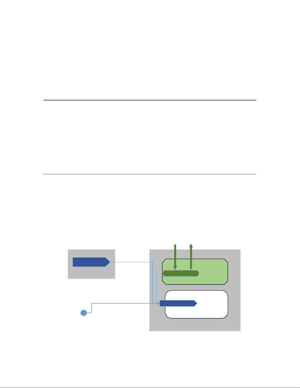
Differences between BACnet and LONWORKS
There is a fundamental difference between BACnet and LONWORKS “Input” and “Output”
concepts pertaining to physical I/O. For example, when considering a temperature
sensor; when using BACnet, the temperature sensor is viewed as an “Analog Input” and
displayed and processed accordingly. In a L
to process the measurement internally and expose the resulting temperature as an
“Analog Output” of a Function Block. Similarly, in the case of a setpoint for example; in
BACnet systems, setpoints are normally considered “Analog Outputs” to be written to a
device, whereas when using L
ONWORKS, setpoints are processed as Analog Inputs to
Function Blocks.
ONWORKS example, the common approach is
With this in mind, the mapping of the BACnet conceptual model to a L
ONWORKS model
can easily be achieved by the creation of a “Virtual BACnet Server” model within the
Neuron Chip, and other BACnet devices interact with this virtual device as they would
with any other native BACnet device.
Figure 1. Conceptual Model of a Virtual BACnet Server
Figure 1 shows 3 L
embodied as the Virtual BACnet Server (VBS) which exists within the Neuron 6050 chip.
It is this interface that a BACnet Client (such as a Building Management System,
Operator Workstation, or perhaps another BACnet Controller) communicates with. The
model of the VBS is such that the BACnet Client can read from and write to BACnet
points in a completely BACnet-compliant fashion. The VBS connects and maps these
BACnet points internally to the L
Normal L
Network Variables in the original function blocks as before, and the L
ONWORKS connections can still be bound, simultaneously, to the LONWORKS
will continue normal operation.
It should be noted that in some cases a single L
multiple SNVT fields will map to Multiple BACnet Objects.
Using BACnet and LONWORKS with the FT 6000 EVK 9
ONWORKS Devices. The central device contains the BACnet Interface,
ONWORKS Network Variables.
ONWORKS Network Variable with
ONWORKS systems
Page 10
FT 6000 based LonWorks Device
Ext ernal Lo nW orks De vi ce
Physic al Sensor
LonWorks Write
Temp from External
Device
Vi rtual BA Cn et S erver
Standard LonWorks Function Block
BAC ne t Wr ite
Fr om B ACn et
Device
BACnet Read
nviSpaceTemp
AO: Space Temp
For example, in Figure 1 there is a nviSpaceTemp that is normally connected to some
other nvo output from another device. If a BACnet Client is required to supply this
parameter, then the BACnet Client will execute a write to the Analog Output
“AO:TempSetpoint” in the Virtual BACnet Server. Internally the BACnet Stack will map
this write to the nviSpaceTemp.
Similarly, if a BACnet Client wants to know the value of a L
ONWORKS output, it would
read the BACnet point mapped to that Network Variable output (nvo).
BACnet Read Operations
When the BACnet Client polls for data, it can request any BACnet Property contained
within the BACnet Object. Most of these properties are rather static (e.g. Object ID,
Object Name) and are seldom polled, sometimes only once, and these types of reads are
handled completely within the VBS.
Reads for live data normally are a BACnet read for the “Present Value” Property of the
BACnet Object, e.g. An Analog Input, Instance 1. This results in the VBS interface
accessing the appropriate “live” data in the L
ONWORKS Network Variable associated with
the BACnet Object.
Write Operation Resolution
BACnet Write operations are more complex within BACnet, and this is further
complicated by the fact that there is a conflict as to who is in control of the point being
written to.
It would be possible to have implemented a “last device to write wins” method. However,
using this approach makes it very difficult to diagnose problems in a system. Luckily,
BACnet already presents a solution, as outlined below.
Figure 2. Write Operation Resolution
10 Using BACnet
Page 11

Out of Service
This is a BACnet-only concept. It allows a BACnet Point to be
Override is a flag that indicates that the BACnet Value being
Fault
A fault indicates some sort of problem with that value or
This is best understood by examining a L
nviSpaceTemp, based on the L
Profile specification, this input can receive data either from a physical sensor, or from
another L
ONMARK and they say that if there is a valid value from another LONWORKS device, this
L
will override the physical input. If the validity of the value expires for any reason,
usually due to the failure to refresh the value in a timely basis, the Functional Block
reverts to using the physical input.
The BACnet Interface extends this model: If there is valid BACnet data available, then
this overrides both the physical input as well as the input from the other L
device.
BACnet has a mechanism for “Commandable Objects”, such as Analog Outputs, that
makes this process seamless; the “Priority Array” and “Relinquish Default”.
The VBS intercepts all LonTalk writes and diverts these to the Relinquish Default. Thus,
if no other BACnet Priority has been written, this value flows through to the NV in the
Function Block.
If a BACnet write occurs at a given priority, then this value is forwarded to the nvi.
However a write to a lower priority is blocked. A write of a NULL value clears the
position in the priority array allowing lower priorities to flow through.
If all the BACnet writes are “Relinquished” (A NULL value is written at all the
appropriate BACnet Priorities), then the Relinquish Default, and hence the nvo from the
external L
no further writes by another BACnet Device, the Priority Array will clear and the system
will revert to using the previous source.
ONWORKS device. The rules for choosing which value to take are laid out by
ONWORKS device, is used again. This means, after a predetermined time with
ONMARK VAV Functional Profile. In the VAV Functional
ONWORKS nvi (in Figure 2), in particular
ONMARK
BACnet statuses such as “Out Of Service” and “Override” and “Fault” are treated as follows:
‘disconnected’ from the live data, in this case the LONWORKS
Network Variable, for testing and diagnostic purposes. It is fully
functional within the VBS but does not impact the functioning of
ONWORKS.
L
Override
reported is no longer a true reflection of the physical value. It is
not appropriate for this model, and is an optional BACnet
Property and so is not included here.
measurement. This condition can be detected by the VBS and is
passed on to the BACnet Client to indicate the condition in a
logical manner.
Note that BACnet allows the Present Value to be read back from a BACnet Output. This
means that a matching BACnet Input is not required for reading back the true value of
any BACnet output. This is significant because it means that the BACnet Outputs in the
VBS allow the BACnet Client to “observe” the Network Variable values set by the
physical sensors or other LonWorks devices at all times, without having to write
anything, and without having to create a ‘shadow’ BACnet input specifically for this
purpose.
Using BACnet and LONWORKS with the FT 6000 EVK 11
Page 12

FT 6000 Based LonWo rks D evic e
Lon Application
( User Code )
Lon Network
Var iable s
BAC ne t St ack
LonTalk Stack
St ati c (Flash/
EEP ROM)
Dynamic
(RAM)
BAC ne t t o
Lon
Mapping
Function
BACnet to Lon
Mapping
Configuration and
Support
Mapping Table
Protocol Layer – IzoT
LonTa lk
Reads and
Wr ite s
BAC ne t
Reads and
Wr ite s
BACnet Interface Overview
The following figure depicts the BACnet interface.
In this figure, the items shown in blue are the normal Neuron Chip functions and data
structures, and the ones in green are the new BACnet related functions and data
structures.
Figure 3. Functional Overview
At the bottom of the diagram, arrows represent both IzoT and BACnet read and write
messages. These can be transferred over FT10, and are not exclusive, so normal
ONWORKS operation can occur at the same time as BACnet activity.
L
BACnet messages are identified by LonTalk Message Codes, and are routed through the
BACnet Stack where they are interpreted, and BACnet-only operations may access the
Mapping Table and respond to the BACnet Client without any further impact to the
LonTalk side of the system.
12 Using BACnet
Page 13

FT 6000 Based LonWo rk s Devi ce
Lon Application
( Us er Cod e)
Lon Network
Var iable s
BAC ne t St ack
LonTalk Stack
St ati c (Flash/
EEP ROM)
Dynamic (RAM)
BAC ne t
Mapping
Function
BACnet to Lon Mapping
Configuration Process
Mapping Table
“Sicbhook ” write
intercept
( 2 )
Protocol Layer – IzoT
LonWorks Write
BACnet messages that do affect the Network Variables are routed via the Mapping
Functions, and then back to the LonTalk stack, where they are presented to the
Application layer completely transparently to the Application Code.
Note that some BACnet properties can be stored in permanent (Flash) memory.
Data Flow during a LONWORKS Write to a Network Variable
The following figure shows data flow when LONWORKS writes to a Network Variable.
Figure 4. Data Flow during LONWORKS Write
A L
noted as (1). During the processing of the write, the BACnet stack is given an
opportunity to examine the message, and if necessary, (2) modify the data content with
higher priority data values (see “write operation resolution” above).
Using BACnet and LONWORKS with the FT 6000 EVK 13
ONWORKS Network Variable write arrives at the LonTalk stack in figure 4, this is
Page 14

The modified or unmodified message is passed back to the LonTalk stack for further
processing as normal at this point (3).
Data Flow during a LONWORKS Read of a Network Variable
The BACnet stack does not participate in this task.
Data Flow during an outgoing Network Variable Update
When the application program on the Neuron updates a Network Variable, an outgoing
ONWORKS message is generated. This message is intercepted by the BACnet Stack and
L
passed on for L
ONWORKS processing like always, without any change.
Data Flow during a BACnet Write to a BACnet Object
A BACnet Write operation is effec tively a LONWORKS Message with a different Message Code Field.
As shown in Figure 4, when the L
through the BACnet stack which extracts the BACnet Properties and values, modifies them to suit a
Network Variable format and passes this new Network Variable information back to the L
stack for further processing.
ONWORKS message is received by the LonTalk Stack (1) it is routed
ONWORKS
Data Types and BACnet to Lon Mapping
The following BACnet Objects are implemented in the BACnet Interface.
AI
AO
AV
BI
BO
BV
Analog Input
Analog Output
Analog Value (These are BACnet-optional, temporary holding re gisters, and are of
no value in t his scenario .)
Binary Input
Binary Output
Binary Value (These are BACnet-optional, temporary holding registers, and are of
no value in t his scenario .)
BACnet Instance Numbering
BACnet Objects are identified by an Object Identifier that comprises a Type and an
Instance Number, the latter being any number between 0 and 2^22-2 (4194302)
inclusive. Object Identifiers have to be unique per BACnet Device, but the Instance
Number only has to be unique per Type. The BACnet Stack on the Neuron uses the
Network Variable Index as part of the BACnet Instance Number.
14 Using BACnet
Page 15

BACnet Object to LONMARK SNVT Mapping – The “Mapping Table”
1. Network Variables
The first issue is that SNVTs are “Structures” and BACnet objects are effectively single
point values, this means that often there is one-to-many mapping required between
ONWORKS and BACnet.
L
For example, in the VAV template, nvoUnitStatus is numbered nv4, and it is a
SNVT_hvac_status which has 7 fields, which means this single NV needs to expand into
7 BACnet Objects with the following Object IDs.
SNVT Map Status
SNVT_hvac_status.mode
SNVT_hvac_status.heat_output_primary
SNVT_hvac_status.heat_output_secondary
SNVT_hvac_status.cool_output
SNVT_hvac_status.econ_output
SNVT_hvac_status.fan_output
SNVT_hvac_status.in_alarm
2. Normal Variables
If normal variables (as opposed to Network Variables) are to be mapped, then alternative
mapping macros need to be used.
Examples of both mapping methods are found in the BAClon\mapping.nc file in both the
BACevb and BACsimple sample projects.
maps to Analog Input
maps to Analog Input
maps to Analog Input
maps to Analog Input
maps to Analog Input
maps to Analog Input
maps to Analog Input
BACnet Object Properties
Object Name Property
The BACnet Object Name Property is automatically determined from the LonWorks
Network Variable name.
Queue Management
If there are more incoming messages than the BACnet stack can handle, these messages
will back up in the Neuron incoming queue, and eventually messages will be discarded
just like any other LonTalk message overrun. This condition can be diagnosed using
familiar tools such as Nodeutil.
Using BACnet and LONWORKS with the FT 6000 EVK 15
Page 16

Device ID and Device Name
The Object ID of the BACnet Device Object (“Device ID”) is required to be unique
“Internetwork Wide”, as is the Object Name of the Device Object (“Device Name”).
As a default, the BACnet Stack synthesizes the ObjectID and Object Name from the
Neuron ID, guaranteeing uniqueness, but for most projects, you should rename and
renumber your devices. This can be achieved by writing a new Device ID and a new
Device name to the system using the BACnet Browser for IzoT or any other standard
BACnet workstation that supports this functionality. These values get stored in
persistent memory and allow failed devices to be replaced without having to reconfigure
the BACnet Clients.
Mapping Table Structure
Not all fields of a SNVT are of interest to all users, so a method of specifying what gets
mapped has been established. The Mapping Table is hard-coded by the programmer in
the file BAClon/mapping.nc. This has been implemented and takes the form of C code
Macro statements, that allow the programmer to specify the NV name of interest, and
the BACnet Mapping desired. An example is shown below.
mapAnaToSNVT_lux ( "Illuminance", localLight),
And for SNVTs with multiple fields..
mapAnaToSNVT_switch__value ( "nvoSwitchOut.value - AI", nvoSwitchOut),
Requirements to add the BACnet Stack to a FT 6050 application
Create a new project as per normal NodeBuilder procedures. When the project has been
set up, copy the BAClon subdirectory from one of the sample projects across to the new
project directory.
Modify the project ‘main’ or ‘OEM source file’, similar to what is shown in the source code
of the sample projects. A few particular #includes and source code modifications have to
be made to an existing project.
1. #includes
a. # include "baclon.h"
Required for BACnet
2. Source file changes
a. In the OEM source file, the following statements are required
16 Using BACnet
#include "BAClon\sys\blonsys.nc"
when (msg_arrives) { if ( handle_BACnet () ) { return; } }
when (reset) { init_BACnet( ); }
Page 17

Refer to the sample source code, in particular BACsimple.nc to see how
this is used.
3. BAClon\mapping.nc
a. This file contains the actual mapping tables that map Network Variables to
BACnet Objects
4. BAClon\mapping.h
a. A header file that contains mapping macros as used by mapping.nc. It can be
extended by the user if required to support UNVTs etc.
Mapping BACnet Objects to Network Variables
Network Variables are mapped to BACnet Objects via entries in this file. There are 4
tables, one table for each BACnet Object type (AI, AO, etc.). Each table has entries,
described in order below:
1. Mapping type - mapAnaTooSNVT_temp_p ( )
This is a C macro that maps the BACnet Object Type to the SNVT type. This
example obviously maps a BACnet Analog Input or Output to a SNVT_temp_p.
Note that SNVT_temp_p is a ‘simple’ Network Variable, a complex case is
described below.
2. Description
Any text string will suffice here. BACnet string lengths are limited to 32
characters.
3. L
ONWORKS Network Variable name
Mapping BACnet Objects to non-Network Variables
“Normal” Variables are mapped in a very similar fashion to Network Variables. Different
macro names are used. For reference, these can be seen in the sample mapping.nc files.
An example is provided here:
mapAnaToNormalVarFloat ( "Loopback Analog Float:AI", floatLoopback ),
mapAnaToNormalVarSShort ( "Loopback Analog Int8:AI", int8Loopback ),
Using BACnet and LONWORKS with the FT 6000 EVK 17
Page 18

Complex Mapping
If a Network Variable has multiple fields, each field needs to be mapped to a separate
BACnet Object. mapAnaToSNVT_hvac_overid__percent ( ) provides a mapping of
SNVT_hvac_overid.percent to a BACnet Analog Output or Input.
It is possible for a BACnet Client to both read from and write to an Output (e.g. Analog
Output), subject to the rules of BACnet Objects, such as “Out-Of-Service” and “Priority
Arrays”
Mapping UNVTs
UNVTs are mapped in a similar fashion to SNVTs, but the mapping macro must be
defined by the OEM developer. Refer to the BAClon\mapping.h file, and use one of the
pre-defined mappings to generate an appropriate mapping for the new UNVT, and then
this new mapping can be applied to the UNVTS in BAClon\mapping.nc file.
Device Object Instance and Name
As mentioned before, a BACnet Device’s Device Object Instance and Device Object Name
must be unique across the whole BACnet Internetwork. The Toolkit automatically
generates a unique instance and name based on the IP address it has been allocated by
the DHCP server on the IzoT Router. This can be changed by the user using a suitable
BACnet Client, and once changed, will remain set in persistent storage.
BACnet Test Tools
1. BACnet Browser for IzoT – This is a standard BACnet Client. All discovered BACnet
devices appear in the tree view in the left pane. Right clicking on a contained BACnet
Object of the appropriate type allows the Present Value and a few of its other
properties to be monitored in the right pane. This utility can be downloaded from the
following link.
http://www.connect-ex.com/demos_and_downloads/bacnet-browser-for-echelons-izot
18 Using BACnet
Page 19

rd
2. 3
3. For much more rigorous testing of your application before submitting to BTL, use the
4. Wireshark is invaluable for analyzing BACnet traffic. A ‘dissector’ for BACnet
http://www.wireshark.org/download.html
Here is a brief tutorial how to use Wireshark
party BACnet Clients – of course, any BACnet Client, in theory, should be able to
read all BACnet points served by the BACnet stack.
BACnet Test Client linked here:
http://www.bac-test.com/downloads/
packets is built in, and a white paper on its use can be found at the following link:
http://www.bacnet.org/Bibliography/BACnet-Today-08/Karg_2008.pdf
Wireshark itself can be found here:
Wireshark can be used on the IP side of the connection to help diagnose
BACnet connectivity issues.
Procedure
1. Obtain and install Wireshark from http://www.wireshark.org/
2. Set up a capture filter (UDP Port 47808) (optional, but suggested to
reduce capture traffic)
3. Start Wireshark
4. BACnet messages will be dissected and displayed.
5. If you did not set up a capture filter, you can set up a display filter so
only BACnet messages are shown.
6. Press the refresh button on the BACnet Browser for IzoT to generate
BACnet traffic.
Using BACnet and LONWORKS with the FT 6000 EVK 19
Page 20

20 Using BACnet
Page 21

Appendix A
Glossary
This appendix provides definitions for terms discussed in this manual.
Using BACnet and LONWORKS with the FT 6000 EVK 21
Page 22

Application Device
A LONWORKS device that runs an ISO/IEC 14908-1 application (OSI Layer 7). The application may
run on a Neuron Chip or Smart Transceiver, in which case the device is called a “Neuron hosted”
device.
Application Image
Device firmware that consists of the object code generated by the Neuron C compiler from the user’s
application program and other application-specific parameters, including the following:
• Network variable fixed and self-identification data
• Network variable device interface data
• Program ID string
• Optional self-identification and self-documentation data
• Number of address table entries
• Number of domain table entries
• Number and size of network buffers
• Number and size of application buffers
• Number of receive transaction records
• Input clock speed of target Neuron Chip or Smart Transceiver
• Transceiver type and bit rate
Application Program
The software code in a L
ONWORKS device tha t defines how it funct ions. The application program,
also referred to as the application, may be in the devi ce when you purchase it, or you may load it into
the device from application image files (.APB, .NDL, and .NXE extensions) using the LonMaker tool
or other network management tool. The application program interfaces with the ISO/IEC 14908-1
firmware to communicate over the network. It may reside completely in the Neuron Chip or Smart
Transceiver, or it may reside on an attached host processor (in a host-based device).
Binding
Process of connecting network variables. Binding creates logical connections (virtual wires) between
ONWORKS devices. Connections define the data that devices share with one another. Tables
L
containin g binding information are stored in the device’s non-volatile memory, and may be updated by
the LonMaker tool or the ISI protocol.
Changeable-Type Network Variable
A network variable that has a type and length that can be changed to that of another network variable
type of equal or smaller size. You can use changeable-type network variables to implement generic
functional blocks that work with differe nt types of inputs and outputs.
Channel
The physical media between devices upon which the devices communicate. The ISO/IEC 14908-1
protocol is media independent; therefore, numerous types of media can be used for channels: twisted
pair, power line, fiber optics, IP, and RF, and other types.
Commissioning
The process in which the LonMaker tool or other network management tool downloads network and
application configuration data into a physical device. For devices whose application programs are not
contained in ROM, the network management tool also downloads the application program into
non-volatile RAM in the device. Devices are usually either commissioned and tested one at a time, or
commissio ned and then brought online and tes ted incrementally.
22 Appendix A – Glossary
Page 23

Configuration Properties (CPs)
Configuration properties are data values that define the behavior of an application device by
determining the manner in which device application data is manipulated and when device application
data is transmitted. Configuration properties can be applied to the device, functional block, or network
variable level. Configuration properties can determine the functions to be performed on the values
stored in network variables. For example, a configuration property may specify a minimum change
that must occur on a physical input to a device before the corresponding output network variable is
updated.
Configured
A device state where the device has both an application image and a configured network image. This
indicates that the device is ready for network operation.
Connection
The implicit addressing established during binding. A connection links one or more logical outputs
(network vari ables or message tags) to one or more logical inputs. A connection may be represented
with a connector shape or a reference connection.
Connect Button
A button on an ISI device that the user can press to create a connection. The Connect button on an
Echelon Series 6000 EVB running the NcSimpleIsiExample or NcMultiSensorExample application is
the SW2 button on the right side of the board.
Connect Light
An LED on an ISI device that provides feedback related to the status of an ISI connection. The
Connect li ght on an Echelon Series 6000 EVB running the NcSimpleIsiExample or
NcMultiSensorExample application is LED2, which is located directly above the SW2 button. Connection Host
A device that initiates the enrollment process by send ing a connection invitation spec ifying a
connection assembly.
Connection Member
A device that has joined an ISI connection, but is not the connection host.
Connector Shape
A single connector used to connect a pair of network variables within the same subsystem.
Control Network Protocol (CNP)
The ISO/IEC 14908-1 Control Network Protocol. The CNP is a complete seven-layer communications
protocol, with each layer optimized to the needs of control applic a tions. The seven la yers follow the
reference model for open systems interconnection (OSI) developed by the International Standard
Organization (ISO).
Data Point
A network variable, configuration property, or functional block state (enabled or in override) that the
LonMaker tool can monitor and/or control.
Data Point Shape
A shape in the LonMaker Basic Stencil of the LonMaker tool that you can use to monitor and control
the values of network variables and configuration properties, and the states of functional blocks
(enabled or in override).
Using BACnet and LONWORKS with the FT 6000 EVK 23
Page 24

Device
A device that communicates on a L
device, network service device, or a router. Devices are sometimes referred to as nodes in L
ONWORKS network using CNP. A device may be an application
ONWORKS
documentation.
Device Interface
The logical interface to a device, abbreviated as XIF. A device’s interface specifies the number and
types of functional blocks; number, types, directions, and connection attributes of network variables;
and the number of message tags. The program ID for a device is used as the key to identify each
device interface. Each program ID uniquely defines the static portion of the interface. However, two
devices with identical static portions may differ if dynamic network variables are added or removed, or
if the types of changeable network variables are changed. Thus it is possible to have devices with the
same program ID but different device interfaces.
Device Interface File (XIF)
A file that documents a device’s interface with a network. The file can be a text file (.XIF extension),
or it can be a binary file (.XFB extension).
Device-Specific Configuration Property
A configuration property that has values that can be modified independent of the network database.
Changes made to a device-specific configuration property are not updated in the network database.
Device Template
A device template contains all the attribut es of a given device type, such as its functional blocks,
network variables, and configuration properties. You can create a device template by importing a
device interface (XIF) file supplied by the device manufacturer, or by uploading the device interface
definition from the physical de vice. A device template is identified by its name and its program ID.
Both must be unique within a network—you cannot have two device templates with the same name or
the same program ID in a single network.
Download
An installation process in which data, such as the application program, network configuration, and/or
application configuration, is transferred over the network into a device.
Free Topology
A connection scheme for the co mmunic a tion bus that eases traditional transmission line restriction s o f
trunks and drops of specified lengths and at specified distances, and terminations at both ends. Free
topology allows wire to be strung from any point to any other, in bus, daisy chained, star, ring, or loop
topologies, or combinations thereof. It only requir es one termination anywhere in the network. This
can reduce the cost of wiring significantly.
Echelon Series 6000 EVB
LONWORKS evaluation board that uses Echelon’s FT 6000 Smart Transceiver. It features a compact
A
design that includes the following I/O devices that you can use to develop prototype devices and run
the Echelon Series 6000 EVB examples: 4 x 20 character LCD display, 4-way joystick with center
push button, 2 push-but t on inputs, 2 LED outputs, light-level sensor, and temperature sensor.
Functional Block (FB)
A collection of network variables, configuration properties, and associated behavior that defines a
specific system functionality. Functional blocks define standard formats and semantics for how
information is exchanged between devices on a network. Each functional block implements a
functional profile.
24 Appendix A – Glossary
Page 25

Functional Block Array
A set of identical functional bloc ks. A functional block arra y is useful if your device c ontains two or
more identical switches, lights, dials, controllers, or other I /O devices that will each have an identical
external interface. In addition, a functional block array saves code space and reduces the number of
when-tasks in your code.
Functional Profile
A template for a functional block that enables equipment specifiers to select the functionality they need
for a system. Each functional profile defines mandatory and optional network variable and
configuration property members along with their intended usage. A number of generic standard
functional profiles are available for generic devices such as simple sensor and actuators. Many
industry-specific standard functional profiles are available for industry-specific applications.
Industry-specific standard profiles are developed through a review and approval process, including a
cross-functional review to ensure the p rofile will interoperate within an ind ividual subsystem and also
provide interoperability with other subsystems in the networ k.
User-defined functional profiles can be created if no appropriate standard profiles are available.
I/O Object
An instantia tion of an I/O model. An I/O objects consists of a specific I/O model, and its pin
assignment, mod i fie rs , and na me.
Interoperable Self-Installation (ISI) Protocol
The standard protocol for performing self-installation in LONWORKS networks. ISI is an
application-layer protocol that lets you install and connect devices without using a separate network
management tool. It is typically used in home networks, and may be used in any network with less
than 200 devices with simple connection and configuration requirements.
ISI Mode
An installation scenario in which the ISI protocol is used (instead of the LonMaker tool or other network tool) to install devices and create network variables connections.
OpenLNS
A network operating system that provides services for interoperable L
maintenance, monitor ing, and control too ls such as the O pe nLNS Co mmi ssio ni ng Tool. Using the
services provided by the OpenLNS client/server architecture, tools from multiple vendors can work
together to install, maintain, monito r, and control L
consists of the following elem e nts:
1. OpenLNS client applications, which can b e used to develop, monitor and control L
networks.
2. The OpenLNS Object Server ActiveX Control, which is a language-independent programming
interface for OpenLNS client applications to access the L
3. The OpenLNS Server, which manages the network and maintains a database containing the
network configuration.
OpenLNS Network Database
ONWORKS network has i ts own OpenLNS network database (also referred to as the network
Each L
database) that is managed and maintained by an OpenLNS Server. The network database includes the
network and device co nfiguration data for that network. The network database also contains extension
records, which are user-defined records for storing application data.
ONWORKS networks. The OpenLNS architecture
ONWORKS network.
ONWORKS installation,
ONWORKS
Using BACnet and LONWORKS with the FT 6000 EVK 25
Page 26

OpenLNS Server Computer
A computer running the OpenLNS Server software. The OpenLNS Server computer contains the
OpenLNS global database, which includes the group of L
ONWORKS networks be i ng managed by the
OpenLNS Server, plus a network database for each network managed by the server.
Out-Of-Service
A BACnet Object can be marked Out-Of-Service, which then allows writes to the Present Value to
take place. However, this value is not allowed to be transferred to the hardware output itself. This is
used for testing.
Local Client
An OpenLNS application running on the same computer as the OpenLNS Server.
Local Device
An Echelon Series 6000 EVB board running the NcMultiSensorExample application that receives
SNVT_lux and/or SNVT_temp_p output network variable updates from another device (a remote
device). The local device displays the temperature and light level values received from the remote
device in the Remote Info Mode panel on its LCD. A remote device may be another Echelon Series
6000 EVB board running the NcMultiSensorExample application.
OpenLNS Commissioning Tool (OpenLNS CT) Browser
An OpenLNS plug-in that provides a table view of the network variables and configuration properties
of selected devices and/or functional blocks. The OpenLNS Brower can be used to monitor and
control the network variables and configuration properties in a netwo rk.
OpenLNS CT Drawing
An OpenLNS drawing contains the graphical representation of a L
ONWORKS network.
OpenLNS Commissioning Tool
An OpenLNS network tool that uses Visio as its graphic a l user interface. The OpenLNS CT is used to
design, commission, maintain, and document distributed control networks comprised of both
ONMARK and other LONWORKS devices.
L
LonMark
A distinctive logo applied to L
standards of the L
ONMARK Interoperability International.
ONWORKS devices that have been certified to the interoperability
LonTalk Protocol
Echelon’s implementation of the ISO/IEC 14908-1 Control Network Protocol (CNP). The LonTalk
protocol provides a standard method for devices on a L
ONWORKS network to exchange data. The
LonTalk protocol defines the format of the messages being transmitted between devices, and it defines
the actions expected when one device sends a message to another. The protocol normally takes the
form of embedded software or firmware code in each device on the network.
ONWORKS Network
L
A network of intelligent devices (such as sensors, actuators, and controllers) that communicate with
each other using a common protocol over one or more communications channels.
ONWORKS Technology
L
The technology that allows for the creation of open, interoperable control networks that communicate
with the ISO/IEC 14908-1 Control Network Protocol. L
ONWORKS technology consists of the tools
and components required to build intelligent device and to install them in control networks.
26 Appendix A – Glossary
Page 27

Managed Network
A network where a shared network management server, such as LNS, is used to perform network
installation.
Mandatory Network Variable/Configuration Property
A network variable/configuration property that must be implemented by the functional block, as
specified by the functional profile t hat the functional block is instantiating.
Monitored Connecti on
A network variable connection in which the current values are being monitored, typically by an HMI.
The connector shape and reference connection in a LonMaker drawing demonstrate monitored
connections.
Network Interface
ONWORKS device that provides a layer 2 or layer 5 LonTalk interface to an external h ost computer
A L
such as a computer or a handheld maintenance tool. Network interfaces include IP-852 interfaces
(i.LON SmartServer with IP-8 52 routing, i.LON 100 e3 plus Internet Server with IP-852 routing, and
the i.LON 600 L
20, and 21 PCI network interfaces
Network Variable (NV)
Network variables allow a device to send and receive data over the network to and from other devices.
Network var iables are data items (such as temperature, the state of a switch, or actuator position
setting) that a particular device application program expects to receive from other devices on the
network (an input network variable) or expects to make available to other devices on the network (an
output network variable ).
ONWORKS-IP Server); the U10 USB network interface; and PCC-10 and PCLTA-10,
Network Variable/Configuration Property Types
A network variable or configuration property type defines the structure and contents of the data object.
A network variable type can be either a standard network variabl e type (SNVT) or a user-defined
network variable type (UNVT). A configuration property type can be a standard configuration
property type (SCPT) or a user-defined configuration property type (UCPT)
Neuron 6000 Processor
Echelon’s next-generation Neur on chip. The N euron 6000 processor is faster, smaller, and cheaper
that previous-generation Neuron chips. T he Neuron 6000 processor includes a fourth processor for
interrupt service routine (ISR) processing.
Neuron C
A programming language based on ANSI C that you can use to develop applications for Neuron Chips
and Smart Transceivers. It includes network communication, I/O, interrupt-handli ng, and
event-handling extensions to ANSI C, which make it a powerful tool for the development of
ONWORKS device applications.
L
Neuron Chip
A semiconductor component spe cifically designed for providing intelligence and networking
capabilities to low-cost control devices. The Neuron Chip includes a communication port for
connections to variou s network t ypes.
Neuron Core
The Neuron core includes up to four processors that provide both communication and application
processing capabilities. Two processors execute the layer 2 through 6 implementation of the ISO/IEC
14908-1 Control Network Protocol and the third executes layer 7 and the application code. Series
6000 chips include a fourth processor for interrupt service routine (ISR) processing.
Using BACnet and LONWORKS with the FT 6000 EVK 27
Page 28

Neuron Firmware
A complete operating system including an implementation of the ISO /I EC 14908-1 protocol used by a
Neuron Chip or Smart Transceiver. The Neuron firmware is a program that is inserted into memory of
a Neuron Chip or Smart Transceiver.
Neuron ID
A 48-bit number assigned to each Neuron core at manufactu re time. Each Neuron Chip has a unique
Neuron ID, making it like a serial number.
Node Object
A functiona l block that monitors the status of all functional blocks i n a device a nd makes the status
information available for monitoring by the LonMaker tool. A L
ONMARK-compliant device that has
more than one functional block must have a no de obje ct.
NodeBuilder Tool
A hardware and software platform that is used to develop applications for Neuron Chips and Echelon
Smart Transceivers. The NodeBuil der tool provides complete support for creating, debugging,
testing, and maintaini ng L
ONWORKS devices. You can use the NodeBuilder tool all to create many
types of devices, including VAV controllers , thermostats, washing machines, card-access readers,
refrigerators, lighting ballasts, blinds, and pumps. You can use these devices in a variety of systems
including building controls, fac tory automation, and transportation.
Non-const Device-specific Configuration Property
A configuration property that can be changed by the device application, an LNS network tool such as
the LonMaker tool, or another tool not based on LNS. An example of a non-const device-specific
configuration property is the SCPTnwrkCnfg configuration property in the Node Object functional
block of the NcMultiSensorExample and NcSimpleIsiExample applications. This configuration
property stores the current network configuration mode (ISI or managed) of the example application.
OffNet
A management mode in which network configuration cha nges are stored in the network database, but
not propagated to the devices on the network. To send the changes to the devices, you place the
LonMaker tool OnNet. If the LonMaker tool is OffNet and attached to the network, you can still
perform read operations on the network.
OnNet
A management mode in which network configuration changes are propagated immediately to the
devices on the networ k.
Optional Network Variable/Configuration Property
A network variable or configura tion property listed as an optional component in a functional profile.
Functional blocks can elect not to implement optional networ k variables or configuration properties
specified by the functional profile t hat the functional block is instantiating.
PCC-10
A type II PC (formerly PCMCIA) card network interface that includes an integral TP/FT-10
transceiver. Other transceiver types can be connected to the PCC-10 via external transceiver “pods”.
Peer-To-Peer
A control strategy in which ind e pendent intelligent devices share in formation directly with each other
and make their own control decisions without the need or delay of using an intermediate, central, or
master controller. Because of the enhanced system reliability introduced by eliminating the master (a
single point of failure) and the red uce d installation and configuration cost in her ent in peer-to-peer
designs, L
ONWORKS technology is intended to implement a peer-to-peer control strategy.
28 Appendix A – Glossary
Page 29

Priority Array
BACnet Outputs are never directly written to (*). A write is achieved by writing to the Present Value
with a priority of 1 to 16. (With prio r ity 1 being the highest). If the write happens to be the highest
priority in t he array of writes, the n this value is transferred to the Present Value. If it is not the highest
priority write, then the present value remains set whatever value is at the highest priority in the array.
(*) subjec t to Out-Of-Service below
Program ID
A unique, 16-hex digit ID that uniquely identifies the d e vice application.
Relinquish Default
To ‘cancel’ a write operation at a given priority, a NUL value is written to the Present Value at the
appropri ate priority. This has the effect of “r elinquishing” (canceling) the value in the Priority Array.
Lower p riority values at this point may be tra ns fer r e d to the Present Value. If no suitable v a lues remain
in the Priority Array, then the Relinquish Default value is transfer red. In the FT 6050 BACnet Stack
implementation, this Relinquish Default is any external Lon input to the Network Variable. See the
BACnet White Paper for more details on this.
Remote Client
An LNS application that communicates with the LNS Server (running on a separate computer) over a
LonWorks c hannel (an I P-852 or TP/XF-1250 channel) or over an LNS/IP interface. The NodeBuilder
tool cannot be run on a remote client, b ut the LonMaker tool and other LNS client software can.
Remote Device
A device that sends SNVT_lux and/or SNVT_temp_p output network variables updates to a n Echelon
Series 6000 EVB running the NcMultiSensorExample application (the local device). The temperature
and light level values are displayed in the Remote Info Mode panel on the LCD of the local device. A
remote device may be another Echelon Series 6000 EVB running the NcMultiSensorExample
application.
Remote Network Interface (RNI)
A network interface that enables you to connect an LNS or OpenLDV-based application to a
ONWORKS network via a TCP/IP connection. RNIs include the i.LON SmartServer, i.LON 100 e3
L
plus Internet Server, and i.LON 600 L
Resource File
A file included with a L
used by integration and development tools. Defined components include networ k variable types,
configuration property types, and functional profiles implemented by the device application. Resource
files hold definitions of standard and user-defined resources, including network variable and
configuration property types, functional profiles, enumerations, and formatting rules to display
network variable and configuration properties in a readable form. Resource files are used during
device development, installation and management. Standard resource files are distributed by
ONMARK International. User-defined resource files are created and managed during device
L
development.
Self-Installed Network
A network that has network addresses and co nnections cr eated wit hout the use of a network
management tool. In a self-installed network, eac h device co ntains code (the Neuron C ISI library,
which implements the ISI protocol) that replaces parts of the network management server’s
functionality, resulting in a network that no longer req uires a special tool o r server to establish net work
communica tion or to change the configuration of the network.
ONWORKS device that defines the components of the device interface to be
ONWORKS-IP Server.
Using BACnet and LONWORKS with the FT 6000 EVK 29
Page 30

Service Button
A push butto n or other ac tuator on a L
ONWORKS device that is used during installation to acquire the
device’s Neuron ID. For a Neuron hosted device, the button is connected to the service pin of the
Neuron Chip or Smart Transceiver. When this pin is activated, the Neuron core sends a broadcast
message containing its Neuron ID and program ID, which is called service pin message or packet. The
method used to implement the Service button varies from device to device. Examples of mechanical
methods include grounding via a push button or using a magnetic reed switch. By attaching one of the
device’s I/O pins to the service pin, the service pin can also be put under software control as long as
the application code is being executed. For example, the device can ground the pin when the device is
moved or when a predefined series of I/O occurs. The service pin can also be used to drive an LED
that indicates the device’s state. The service LED is solid o n when the device is applicationless, blinks
slowly when the device has an application and is unconfigured, is off when the device has an
application and is configured. Some applications also implement additional ser vice pin blink patterns.
Standard Configuration Property Type (SCPT)
A standard configuration property type defined by L
ONMARK International to facilitate
interoperability. SCPTs are defined for a wide range of configuration properties used in many kinds of
functional profiles, such as hysteresis bands, default values, minimum and maximum limits, gain
settings, and delay times. SCP Ts should be used in a L
ONWORKS network wherever applicable. In
situations where there is not an appropriate SCPT available, manufacturers may define UCPTs for
configuring their devices.
In addition to standard or user-defined network variable types, which define the data type, formatting
rules, limits and units, SCPT also de fine semantics. For example, the SNVT_time_sec standard
network variable type defines a data type for exchanging durations of time, in seconds. The
SCPTmaxSentTime standard co nfiguration property type references SNVT_time_sec, but adds
semantics by clarifying that this configuration property defines the maximum period of time between
consecutive transmiss ions of the current value. See types.lonmark.org for a current list and
documentation.
Standard Functional Pr ofile
A standard set of functional profiles de fined by L
ONMARK International. See types.lonmark.org for a
current list and documentation. See Functional Profile for more information about functional profiles.
Standard Network Var i able Type (SNVT)
A standard set of network variable types defined by L
ONMARK International to facilitate
interoperability by providing a well-defined interface for communication between devices made by
different manufacturers. See types.lonmark.org for a current list and documentation.
Stencil
A collection of master shapes that can be reused in Visio.
TP/FT-10
The free topology twisted pair L
ONWORKS channel type, 78Kbps bit rate.
User-defined Configuration Property Type (UCPT)
A non-standard data structure used for configuration of the application program in a L
ONMARK device.
UCPTs should be used only when there is no appropriate standard configuration property type (SCPT)
defined. L
ONMARK-certified devices must have UCPTs documented in resource files according to a
standard format, in order to allow the devices to be configured without the need for propr i etary
configuration tools. See Standard Configuration Property Type (SCPT) for more information on
configuration property types.
30 Appendix A – Glossary
Page 31

User-defined Functional Profile
A non-standard functional profile defined by a device manufacturer. A user-defined functional profile
should be used only when there is no appropriate standard functional profile defined. See Functional
Profile for more information about functional profile templates.
The NcMulitSensor example uses four UFPTs that inherit from existi ng SFPTs. Three of the UFPTs
are required because no SFPT includes the configuration properties required by the example
application for setting alarm limits and viewing alarm conditions. Another UFPT is req uired b ecause it
uses a changeable-type network variable that is not used by the SFPT from which it inherits.
User-defined Network Variable Type (UNVT)
A non-standard network variable type defined by the manufacturer of a device. UNVTs should be
used only when there is no appropriate standard network variable type (SNVT) defined.
ONMARK-certified devices must have UNVTs documented in resource files according to a standard
L
format, in order to allow the devices to be interoperable.
Virtual Functional Block
A static functional block that that contains the network inputs and outputs for a device that are not part
of other functional blocks on the device.
Using BACnet and LONWORKS with the FT 6000 EVK 31
Page 32

 Loading...