

Page 1

i.LON®SmartServer 2.0
Programmer's Reference
®
078-0347-01D
Page 2

Echelon, LON, LONWORKS, LonTalk, Neuron, LONMARK, 3120, 3150, LNS,
LonMaker, and the Echelon logo are trademarks of Echelon Corporation
registered in the United States and other countries. LonPoint and LonSupport
are trademarks of Echelon Corporation.
Other brand and product names are trademarks or registered trademarks of
their respective holders.
Neuron
for use in equipment or systems which involve danger to human health or
safety or a risk of property damage and Echelon assumes no responsibility or
liability for use of the Neuron
Parts manufactured by vendors other than Echelon and referenced in this
document have been described for illustrative purposes only, and may not
have been tested by Echelon. It is the responsibility of the customer to
determine the suitability of these parts for each application.
ECHELON MAKES NO REPRESENTATION, WARRANTY, OR CONDITION OF ANY
KIND, EXPRESS, IMPLIED, STATUTORY, OR OTHERWISE OR IN ANY
COMMUNICATION WITH YOU, INCLUDING, BUT NOT LIMITED TO, ANY IMPLIED
WARRANTIES OF MERCHANTABILITY, SATISFACTORY QUALITY, FITNESS FOR ANY
PARTICULAR PURPOSE, NONINFRINGEMENT, AND THEIR EQUIVALENTS.
No part of this publication may be reproduced, stored in a retrieval system,
or transmitted, in any form or by any means, electronic, mechanical,
photocopying, recording, or otherwise, without the prior written permission of
Echelon Corporation.
Printed in the United States of America.
Copyright ©1997–2010 by Echelon Corporation.
Echelon Corporation
www.echelon.com
Chips, LonPoint Modules, and other OEM Products were not designed
Chips or LonPoint Modules in such applications.
ii
Page 3

Table of Contents
1 Introduction to the SmartServer SOAP/XML Interface ............... 1-1
1.1 About This Document......................................................................1-1
1.2 Programming Samples....................................................................1-2
1.3 Getting Started ................................................................................1-2
1.4 SmartServer SOAP/XML Interface Upgrades.................................1-2
1.4.1 Version 4.0 SOAP Message Name Schema.............................1-3
2 SOAP Messages and the SmartServer WSDL File...................... 2-1
2.1 SmartServer Naming Structure .......................................................2-1
2.2 SmartServer WSDL File..................................................................2-2
2.3 Security............................................................................................2-2
2.4 SOAP Request and Response Message Structure.........................2-2
2.4.1 SOAP Request ..........................................................................2-3
2.4.2 SOAP Response .......................................................................2-4
2.5 SOAP Messages Formats...............................................................2-4
2.5.1 SOAP Envelope.........................................................................2-5
2.5.2 SOAP Header............................................................................2-5
2.5.3 SOAP Body................................................................................2-6
2.5.4 Namespace................................................................................2-9
2.5.5 SOAP Message Schema...........................................................2-9
2.5.6 SOAP Function Types...............................................................2-9
2.5.7 SOAP Message Attributes.......................................................2-11
2.5.8 Using xSelect Statements in SOAP Message Requests ........2-11
2.6 Data Point References ..................................................................2-14
2.7 UCPTcurrentConfig.......................................................................2-15
2.8 Fault Structure...............................................................................2-15
2.9 LonString type ...............................................................................2-15
2.10 SOAP Message Examples............................................................2-15
2.10.1 Configuration Data.................................................................2-16
2.10.2 Web Binding ..........................................................................2-17
2.10.3 Data Log Read ......................................................................2-18
3 SmartServer Applications and the SOAP/XML Interface............ 3-1
3.1 Overview of SmartServer Applications............................................3-1
3.2 SmartServer XML Configuration Files.............................................3-2
3.2.1 Modifying the XML Configuration Files......................................3-2
3.3 SmartServer Resource Files ...........................................................3-3
3.3.1 Standard Network Variable Type (SNVT)
Device Resource Files...............................................................
3.3.2 Standard Configuration Property Type (SCPT)
Device Resource Files...............................................................
3.3.3 User-Defined Network Variable Type (UNVT)
Device Resource Files...............................................................
3.3.4 User-Defined Configuration Property Type (UCPT)
Device Resource Files...............................................................
3.3.5 Data Point Templates................................................................3-4
3.3.6 Data Formatting.........................................................................3-4
3.4 SOAP Functions..............................................................................3-5
3.4.1 List Functions ............................................................................3-5
3.4.2 Get Functions ............................................................................3-6
3.4.3 Set Functions.............................................................................3-6
3.4.4 Read Functions .........................................................................3-7
i.LON SmartServer 2.0 Programmer’s Reference
iii
3-3
3-3
3-4
3-4
Page 4

3.4.5 Write Functions..........................................................................3-7
3.4.6 Delete Functions........................................................................3-7
3.5 Performance Issues.........................................................................3-7
4 Using the SmartServer Data Server ............................................. 4-1
4.1 Creating and Modifying the Data Point XML Files...........................4-2
4.2 Overview of the Data Point XML File ..............................................4-3
4.3 Data Server SOAP Interface ...........................................................4-4
4.3.1 Using the List Function on the Data Server...............................4-4
4.3.2 Using the Get Function on the Data Server ..............................4-5
4.3.3 Using the Set Function on the Data Server.............................4-10
4.3.4 Using the Read Function on the Data Server..........................4-11
4.3.5 Using the Write Function on the Data Server..........................4-15
4.3.6 Using the Invoke Function to Reset Data Point Priorities .......4-17
4.3.7 Data Point Values and Priority Levels.....................................4-17
4.3.8 Using the Delete Function on the Data Server........................4-18
4.4 Using the Web Binder Application.................................................4-19
4.4.1 Using the List Function on a Web Connection ........................4-20
4.4.2 Using the Get Function on a Web Connection........................4-21
4.4.3 Using the Set Function on a Web Connection ........................4-23
4.4.4 Using the Delete Function on a Web Connection ...................4-24
5 Data Loggers.................................................................................. 5-1
5.1 Overview of the Data Logger XML File ...........................................5-1
5.2 Creating and Modifying the Data Logger XML File .........................5-2
5.3 Data Logger SOAP Interface...........................................................5-3
5.3.1 Using the List Function on a Data Logger.................................5-3
5.3.2 Using the Get Function on a Data Logger.................................5-4
5.3.3 Using the Set Function on a Data Logger .................................5-8
5.3.4 Using the Read Function on a Data Logger..............................5-9
5.3.5 Using the Clear Function on a Data Logger............................5-12
5.3.6 Using the Delete Function on a Data Logger ..........................5-13
6 Alarm Generator............................................................................. 6-1
6.1 Overview of the Alarm Generator XML File.....................................6-1
6.2 Creating and Modifying the Alarm Generator XML File ..................6-2
6.3 Alarm Generator SOAP Interface....................................................6-2
6.3.1 Using the List Function on an Alarm Generator ........................6-3
6.3.2 Using the Get Function on an Alarm Generator........................6-3
6.3.3 Using the Set Function on an Alarm Generator ......................6-12
6.3.4 Using the Delete Function on an Alarm Generator .................6-13
7 Alarm Notifier ................................................................................. 7-1
7.1 Overview of the AlarmNotifier XML File ..........................................7-2
7.2 Creating and Modifying the Alarm Notifier XML File .......................7-3
7.3 Alarm Notifier SOAP Interface.........................................................7-4
7.3.1 Using the List Function on an Alarm Notifier.............................7-4
7.3.2 Using the Get Function on an Alarm Notifier.............................7-5
7.3.3 Using the Set Function on an Alarm Notifier ...........................7-17
7.3.4 Using the Read Function on an Alarm Notifier........................7-18
7.3.5 Using the Write Function on an Alarm Notifier Log File ..........7-22
7.3.6 Using the Clear Function on an Alarm Notifier Log File..........7-23
7.3.7 Using the Delete Function on an Alarm Notifier ......................7-24
8 Analog Function Block.................................................................. 8-1
8.1 Overview of the AnalogFB XML File ...............................................8-1
i.LON SmartServer 2.0 Programmer’s Reference
iv
Page 5

8.2 Creatin g a n d M o di f yi n g th e A n al o g F u n ct i on a l B lo c k X M L Fi le...........8-2
8.3 Analog Functional Block SOAP Interface........................................8-2
8.3.1 Using the List Function on an Analog Functional Block............8-2
8.3.2 Using the Get Function on an Analog Functional Block............8-3
8.3.3 Using the Set Function on an Analog Functional Block ..........8-12
8.3.4 Using the Delete Function on an Analog Function Block........8-13
9 Scheduler........................................................................................ 9-1
9.1 Overview of the Scheduler XML File...............................................9-2
9.2 Creating and Modifying the Scheduler XML File.............................9-3
9.3 Scheduler SOAP Interface ..............................................................9-3
9.3.1 Using the List Function on a Scheduler.....................................9-4
9.3.2 Using the Get Function a Scheduler .........................................9-4
9.3.3 Using the Read Function on a Scheduler................................9-12
9.3.4 Using the Set Function on a Scheduler...................................9-14
9.3.5 Using the Delete Function on a Scheduler..............................9-17
10 Calendar........................................................................................ 10-1
10.1 Overview of the Calendar XML File...............................................10-1
10.2 Creating and Modifying the Calendar XML File.............................10-2
10.3 Calendar SOAP Interface..............................................................10-2
10.3.1 Using the List Function on a Calendar ..................................10-2
10.3.2 Using the Get Function a Calendar.......................................10-2
10.3.3 Using the Set Function on a Calendar ................................10-12
10.3.4 Using the Read Function on a Calendar .............................10-13
10.3.5 Using the Delete Function on a Calendar ...........................10-15
11 Real-Time Clock........................................................................... 11-1
11.1 Overview of the Real-Time Clock XML File...................................11-1
11.2 Creating and Modifying the Real-Time Clock XML File ................11-1
11.3 Real-Time Clock SOAP Interface..................................................11-2
11.3.1 Using the List Function on a Real-Time Clock......................11-2
11.3.2 Using the Get Function on a Real-Time Clock......................11-2
11.3.3 Using the Set Function on a Real-Time Clock ......................11-4
11.3.4 Using the Delete Function on a Real-Time Clock.................11-5
12 Type Translator............................................................................ 12-1
12.1 Overview of the Type Translator XML File....................................12-1
12.2 Creating and Modifying the Type Translator XML File..................12-2
12.3 Type Translator SOAP Interface...................................................12-2
12.3.1 Using the List Function on a Type Translator .......................12-2
12.3.2 Using the Get Function on a Type Translator .......................12-3
12.3.3 Using the Set Function on a Type Translator........................12-5
12.3.4 Pre-Defined Type Translator Rules.......................................12-6
12.3.5 Using the Delete Function on a Type Translator.................12-14
13 Type Translator Rules ................................................................. 13-1
13.1 Type Translator Rule XML Files....................................................13-1
13.2 Creating and Modifying the Type Translator Rule XML Files........13-2
13.3 Type Translator Rule SOAP Interface...........................................13-2
13.3.1 Using the List Function on a Type Translator Rule...............13-3
13.3.2 Using the Get Function on a Type Translator Rule...............13-3
13.3.3 Using the Set Function on a Type Translator Rule .............13-11
13.3.4 Using the Delete Function on a Type Translator Rule ........13-12
i.LON SmartServer 2.0 Programmer’s Reference
v
Page 6

14 LONWORKS Driver ......................................................................... 14-1
14.1 LONWORKS Networks.....................................................................14-1
14.1.1 Using the List Function on a LONWORKS Network .................14-1
14.1.2 Using the Get Function on a LONWORKS Network ................14-1
14.1.3 Using the Set Function on a LONWORKS Network.................14-5
14.1.4 Using the Delete Function on a LONWORKS Network..........14-11
14.2 LONWORKS Channels...................................................................14-11
14.2.1 Using the List Function on a LONWORKS Channel ..............14-11
14.2.2 Using the Get Function on a LONWORKS Channel ..............14-12
14.2.3 Using the Set Function on a LONWORKS Channel...............14-16
14.2.4 Using the Delete Function on a LONWORKS Channel..........14-16
14.3 LONWORKS Devices.....................................................................14-17
14.3.1 Using the List Function on a LONWORKS Device.................14-17
14.3.2 Using the Get Function on a LONWORKS Device .................14-19
14.3.3 Using the Set Function on a LONWORKS Device.................14-26
14.3.4 Using the Delete Function on a LONWORKS Device............14-32
14.4 Routers........................................................................................14-32
14.5 Remote Network Interface...........................................................14-34
14.6 LONWORKS Functional Blocks .....................................................14-34
14.6.1 Using the List Function on a LONWORKS
Functional Block..................................................................
14.6.2 Using the Get Function on a LONWORKS
Functional Block..................................................................
14.6.3 Using the Set Function on a LONWORKS
Functional Block..................................................................
14.6.4 Using the Delete Function on a LONWORKS
Functional Block..................................................................
14.7 Network Variables (LONWORKS Data Points)..............................14-40
14.7.1 Using the List Function on Network Variables ....................14-40
14.7.2 Using the Get Function on Network Variables ....................14-41
14.7.3 Using the Set Function on a Network Variable ...................14-45
14.7.4 Using the Delete Function on a Network Variable ..............14-45
14.8 Configuration Properties (LONWORKS Data Points).....................14-46
14.9 LONWORKS Connections..............................................................14-47
14-35
14-36
14-39
14-40
15 Modbus Driver.............................................................................. 15-1
15.1 Modbus Channels..........................................................................15-1
15.1.1 Using the List Function on Modbus Channels.......................15-1
15.1.2 Using the Get Function on Modbus Channels ......................15-1
15.1.3 Using the Set Function on Modbus Channels.......................15-5
15.1.4 Using the Delete Function on Modbus Channels..................15-6
15.2 Modbus Devices............................................................................15-7
15.2.1 Using the List Function on Modbus Devices.........................15-7
15.2.2 Using the Get Function on Modbus Devices.........................15-7
15.2.3 Using the Set Function on Modbus Devices .........................15-9
15.2.4 Using the Delete Function on Modbus Devices ..................15-10
15.3 Modbus Virtual Functional Blocks...............................................15-10
15.4 Modbus Data Points....................................................................15-10
15.4.1 Using the List Function on Modbus Data Points .................15-11
15.4.2 Using the Get Function on Modbus Data Points.................15-12
15.4.3 Using the Set Function on Modbus Data Points .................15-16
15.4.4 Using the Delete Function on Modbus Data Points ............15-17
16 M-Bus Driver................................................................................. 16-1
16.1 M-Bus Channels............................................................................16-1
i.LON SmartServer 2.0 Programmer’s Reference
vi
Page 7

16.1.1 Using the List Function on M-Bus Channels .........................16-1
16.1.2 Using the Get Function on M-Bus Channels.........................16-1
16.1.3 Using the Set Function on M-Bus Channels .........................16-4
16.1.4 Using the Delete Function on M-Bus Channels ....................16-5
16.2 M-Bus Devices ..............................................................................16-6
16.2.1 Using the List Function on M-Bus Devices............................16-6
16.2.2 Using the Get Function on M-Bus Devices ...........................16-6
16.2.3 Using the Set Function on M-Bus Devices..........................16-10
16.2.4 Using the Delete Function on M-Bus Devices.....................16-11
16.3 M-Bus Virtual Functional Blocks..................................................16-11
16.4 M-Bus Data Points.......................................................................16-11
16.4.1 Using the List Function on M-Bus Data Points....................16-12
16.4.2 Using the Get Function on M-Bus Data Points ...................16-12
16.4.3 Using the Set Function on M-Bus Data Points....................16-15
16.4.4 Using the Delete Function on M-Bus Data Points...............16-16
17 Virtual Driver................................................................................. 17-1
17.1 Virtual Channels............................................................................17-1
17.1.1 Using the List Function on Virtual Channels .........................17-1
17.1.2 Using the Get Function on Virtual Channels.........................17-1
17.1.3 Using the Set Function on Virtual Channels .........................17-3
17.1.4 Using the Delete Function on a Virtual Channel ...................17-4
17.2 Virtual Devices...............................................................................17-4
17.2.1 Using the List Function on Virtual Devices............................17-4
17.2.2 Using the Get Function on Virtual Devices............................17-4
17.2.3 Using the Set Function on Virtual Devices............................17-6
17.2.4 Using the Delete Function on Virtual Devices.......................17-7
17.3 Virtual Functional Blocks...............................................................17-7
17.4 Virtual Data Points.........................................................................17-8
17.4.1 Using the List Function on Virtual Data Points......................17-8
17.4.2 Using the Get Function on Virtual Data Points......................17-9
17.4.3 Using the Set Function on Virtual Data Points....................17-11
17.4.4 Using the Delete Function on Virtual Data Points...............17-12
18 File System Data .......................................................................... 18-1
18.1 Using the List Function on File System Data................................18-1
18.2 Using the Read Function on File System Data .............................18-1
18.3 Using the Write Function on File System Data..............................18-3
18.4 Using the Delete Function on File System Data............................18-4
19 System Information Methods...................................................... 19-1
19.1 System Service Methods...............................................................19-1
19.1.1 TCP/IP Settings.....................................................................19-2
19.1.2 Time Settings.........................................................................19-4
19.1.3 Security Settings....................................................................19-5
19.1.4 Static System Information......................................................19-7
19.1.5 Real-Time System Information..............................................19-9
19.1.6 E-Mail Settings ....................................................................19-11
19.1.7 IP-852 Router Settings ........................................................19-12
19.1.8 IP-852 Router Statistics.......................................................19-14
19.1.9 LonScanner Protocol Analyzer............................................19-15
19.1.10 Reboot...............................................................................19-16
19.2 System Test Methods..................................................................19-16
19.2.1 SMTP E-Mail Server Test....................................................19-16
19.2.2 IP-852 Configuration Server Test........................................19-19
19.2.3 Connection Test ..................................................................19-20
i.LON SmartServer 2.0 Programmer’s Reference
vii
Page 8

20 Using the SOAP Interface as a Web Service ............................. 20-1
20.1 Referencing and Inheriting from the WSDL...................................20-1
20.1.1 Referencing and Inheriting from the WSDL
Using .NET 3.5 Framework...................................................
20.1.2 Referencing and Inheriting from the WSDL
Using .NET 2.0 Framework...................................................
20.2 Instantiating and Initializing the Web Service Client ...................20-11
20.2.1 Instantiating the Web Service Client in
Visual C# .NET 3.5..............................................................
20.2.2 Instantiating the Web Service Client in
Visual C# .NET 2.0..............................................................
20.2.3 Instantiating the Web Service Client in
Visual Basic .NET 3.5..........................................................
20.3 Calling Web Services Methods....................................................20-14
20.3.1 Reading and Writing Data Point Values in
Visual C# .NET 3.5..............................................................
20.3.2 Reading and Writing Data Point Values in
Visual C# .NET 2.0..............................................................
20.3.3 Reading and Writing Data Point Values in
Visual Basic .NET 3.5..........................................................
20.4 Accepting a Web Binding From a SmartServer...........................20-20
20-1
20-6
20-11
20-13
20-14
20-15
20-16
20-19
21 Programming Examples.............................................................. 21-1
21.1 Visual C#.NET Examples..............................................................21-1
21.1.1 Reading and Writing Data Point Values in
Visual C# .NET......................................................................
21.1.2 Creating and Reading a Data Logger in Visual C# .NET......21-2
21.1.3 Creating a Scheduler and Calendar in
Visual C# .NET......................................................................
21.1.4 Creating and Installing a LONWORKS Device in
Visual C# .NET....................................................................
21.1.5 Commissioning External Devices in
Visual C# .NET....................................................................
21.1.6 Discovering and Installing External Devices
in Visual C# .NET................................................................
21.1.7 Configuring the SmartServer in
Visual C# .NET....................................................................
21.2 Visual Basic.NET Examples........................................................21-30
21.2.1 Reading and Writing Data Point Values in
Visual Basic.NET.................................................................
21.2.2 Creating and Reading a Data Logger in
Visual Basic. NET...............................................................
21.2.3 Creating a Scheduler and Calendar in
Visual Basic.NET.................................................................
21.2.4 Creating and Installing a LONWORKS Device in
Visual Basic.NET.................................................................
21.2.5 Commissioning External Devices in
Visual Basic.NET.................................................................
21.2.6 Discovering and Installing External Devices in
Visual Basic.NET.................................................................
21.2.7 Configuring the SmartServer in Visual Basic.NET..............21-51
21-1
21-7
21-15
21-18
21-21
21-26
21-30
21-31
21-34
21-42
21-44
21-47
22 Programming the SmartServer with Java.................................. 22-1
22.1 Setting up the Java Programming Environment............................22-1
i.LON SmartServer 2.0 Programmer’s Reference
viii
Page 9

22.1.1 Installing Echelon SmartServer JAX-ES
Programming Example..........................................................
22.1.2 Installing Eclipse IDE for Java EE Developers......................22-1
22.1.3 Installing the Java Development Kit ......................................22-1
22.1.4 Installing Maven 2.2.1............................................................22-1
22.1.5 Setting System Environment Variables.................................22-2
22.2 Creating a JAX-WS Client.............................................................22-3
22.3 Java Programming Examples......................................................22-17
22.3.1 Reading and Writing Data Point Values in Java .................22-17
22.3.2 Creating and Reading a Data Logger in Java.....................22-19
22.3.3 Creating and Installing a LONWORKS Device in Java ..........22-23
22.3.4 Discovering and Installing External Devices in JAVA .........22-26
22-1
Appendix A: SOAP Tester Example...................................................A-1
i.LON SmartServer 2.0 Programmer’s Reference
ix
Page 10

i.LON SmartServer 2.0 Programmer’s Reference
x
Page 11

1 Introduction to the SmartServer SOAP/XML Interface
The SmartServer contains a powerful microprocessor with a real-time, multi-tasking operating system
that manages its various applications. These applications include alarming, scheduling, data logging
and network variable type translation. Generally, you will configure these applications with the
SmartServer Web pages, as described in the i.LON SmartServer 2.0 User’s Guide. The i.LON
SmartServer 2.0 User’s Guide provides instructions to follow when configuring the SmartServer
applications with the SmartServer Web interface, as well as general information on the different
SmartServer applications, and guidelines to follow when using these applications.
You can also use the SOAP/XML interface provided with the SmartServer to configure these
applications. XML is a universal format used to deliver data through structured documents over the
Web. It allows developers to store data for any application in a standard, consistent way. SOAP is a
protocol for exchanging XML-based messages over TCP/IP networks, normally using HTTP. SOAP
enables different applications and devices to communicate with each other, regardless of platform, by
sending SOAP messages to each other.
The configuration of each SmartServer application is stored in an XML file. The SmartServer reads
these files during its boot process, and sets the operating parameters of each application based on the
configuration data contained in the XML file for that application.
The SmartServer includes a set of SOAP functions that you can use to create and manage the
configuration of each application. Each time you invoke any of these functions, a SOAP message is
sent to the SmartServer. The content of the SOAP message is based on the input you supply to the
function. The SmartServer reads the contents of the message, writes the contents of the message to the
applicable XML file, and adjusts the operating parameters of its applications accordingly. All of this
occurs while the SmartServer is operating.
It is important to note that the XML files described in this document store the configurations of the
SmartServer applications. They do not store the data generated by these applications. The real-time
data generated by the SmartServer's applications is stored in RAM and log data are stored on the flash
disk.
However, this does not mean that application configuration is the only task you can perform with the
SmartServer SOAP/XML interface. The SOAP/XML interface also includes functions you can use to
access, read and analyze the data generated by the SmartServer applications. And so you can use the
SOAP/XML interface not only to configure the various applications of the SmartServer, but to monitor
them as well.
1.1
About This Document
This document describes the XML files that store the configurations of the various SmartServer
applications, and the SOAP functions you can use with each application. The SOAP interface
provided with the SmartServer conforms to the SOAP 1.1 proposed Technical Recommendation:
http://www.w3.org/TR/2000/NOTE-SOAP-20000508
This document also describes how to configure the SmartServer applications by manually creating and
modifying the XML configuration files. Once you have created the XML files, you can download
them to the SmartServer via FTP. The SmartServer will read the downloaded files and adjust its
operating parameters accordingly the next time it is rebooted.
You can create or modify the files using any XML editor or ASCII text editor. This document
provides examples you can use when creating the XML configuration files for your SmartServer, and
instructions to follow when downloading these files to the SmartServer. The XML files used by the
SmartServer applications conform to the XML 1.0 Technical Recommendation:
http://www.w3.org/TR/2000/REC-xml-20001006
i.LON SmartServer 2.0 Programmer’s Reference
1-1
Page 12

Echelon strongly recommends that you use the SOAP interface to configure the applications of
your SmartServer. The SmartServer performs error-checking on all data written in a SOAP message,
so that invalid data will not be written to any of the XML files. The SmartServer will not perform
error-checking on any XML files downloaded to it via FTP, and so manually editing the XML files
may cause errors during the boot process. Additionally, you can send SOAP messages to the
SmartServer while it is operating, and the SmartServer will update the XML files affected by the
SOAP messages without requiring a reboot.
You may find the information in this document that pertains to manually creating and managing XML
files useful if you are using several SmartServers, and would like to use the same configuration on
each one. In that case, you could configure one of the SmartServers, copy its XML files, and
download them to the appropriate directories of the other SmartServers to obtain the same
configuration in all of them.
1.2
Programming Samples
Chapter 21 of this document includes programming samples written in
.NET, and Java
understood, they have been simplified. Error checking has been removed, and in some cases, the
examples are only fragments that may not compile without errors or warnings.
1.3
Getting Started
You should review Chapters 2 and 3 before proceeding to the rest of this document and learning about
the functions and applications of the SOAP/XML interface. Chapter 2,
SmartServer WSDL, describes the WSDL file which defines the SOAP/XML interface. Chapter 3,
SmartServer Applications and the SOAP/XML Interface, provides an overview of the SmartServer
applications and includes a roadmap to follow when configuring those applications with a SOAP
application.
You can begin to learn how to program the SmartServer using SOAP/XML using the iLON SOAP
Tester (version 2.0.3994). The SOAP Tester is an unsupported engineering-level tool provided by
Echelon that lets you perform functional testing of the SmartServer’s pre-defined SOAP functions and
your user-defined SOAP functions. You can do w nl oad the SOAP Tester from the i.LON SmartServer
Community Web site at
4.03), the SOAP Tester is also included on the i.LON SmartServer 2.0 DVD in the
iLon100\iLon100\unsupported\SoapTester folder. For more information on using the SOAP Tester,
Appendix A: SOAP Tester Example.
see
You can also learn how to program the SmartServer using SOAP/XML by installing an HTTP
debugging proxy program like Charles on your computer. The Charles proxy records all SOAP and
other HTTP traffic to and from your computer. You can use Internet Explorer to perform normal
operations with the SmartServer Web interface and record the SOAP messages that are being sent to
the SmartServer. You can download a free trial version of the Charles proxy from the Charles Web
site. For more information on using and downloading the Charles proxy, go to the Charles Web site at
www.charlesproxy.com.
to illustrate concepts described in this manual. To make these samples more easily
http://ilonsmartserver.com/files. If you have a SmartServer 2.0 (Release
Visual C# .NET, Visual Basic
SOAP Messages and the
1.4
SmartServer SOAP/XML Interface Upgrades
The format and contents of the SOAP messages you can send to a SmartServer are defined by the
SOAP namespace that the SmartServer is using. The SOAP/XML interface used for the SmartServer
(software version 4.0) is new. It uses a common set of generic methods (list, get, set, delete, read,
write, clear, and invoke) for retrieving and configuring the data of the various SmartServer
applications. This differs from the SOAP/XML interface that was used for e3 (software version 3.0)
release, in which each application had its own specialized set of messages and structures.
There have been three different SOAP namespaces introduced during the four releases of the i.LON
servers. The version 1.0 namespace was introduced for Release 1.0, the version 1.1 namespace was
i.LON SmartServer 2.0 Programmer’s Reference
1-2
Page 13

introduced for the e2 release, and the version 3.0 namespace was introduced for the e3 release.
Support for the different namespaces as follows:
• i.LON 100 servers running the Release 1.0 software only support the version 1.0 namespace. This
means that a SmartServer running the Release 1.0 software can only respond to SOAP messages
from other SmartServers running the Release 1.0 software.
• i.LON 100 servers running the e2 software support the version 1.0 and 1.1 namespaces. This
means that an i.LON 100 server running the e2 software can respond to SOAP messages from
other i.LON 100 servers that are running the Release 1.0 or the e2 software.
• i.LON 100 servers running the e3 software support the version 1.1 and 3.0 namespaces. This
means that i.LON 100 servers running the e3 software can respond to SOAP messages sent from
other i.LON 100 servers that are running the e2 or e3 software.
• SmartServers running the SmartServer software support only the version 4.0 namespace. This
means that SmartServers running the SmartServer software can respond to SOAP messages sent
from other SmartServers. SmartServers running the SmartServer software cannot respond to
SOAP messages sent from i.LON 100 servers running the e3 software.
The following section,
SOAP/XML interface between SOAP namespace versions ‘3.0’ and ‘4.0’ (i.e. between the e3 and
SmartServer releases).
Note: This manual often refers to the i.LON 100 and SmartServer releases by the version numbers
used in their SOAP namespace. For example, the SmartServer release is referred to by its software
version number, which is ‘4.0’, and the i.LON 100 e3 release is referred to as ‘3.0’. For more
information on the SOAP namespace, see
1.4.1
Version 4.0 SOAP Message Name Schema
The SOAP/XML interface used for the SmartServer (version 4.0) uses a new message name schema.
It uses a common set of generic methods (List, Get, Set, Delete, Read, Write, Clear, and Invoke) for
retrieving and configuring the data of the var i ous SmartServer applications. This section provides an
overview of the changes made to the SOAP message name schema from version 3.0.
Version 4.0 SOAP Message Name Schema, describes the changes made to the
Chapter 2 of this document.
1.4.1.1 Version 3.0 Message Name Schema
The message name schema used for version 3.0 was <Application>_<Message>_<Parameter>. The
Parameter was optional and normally not used. The Message was normally List, Get, Set or Delete.
The following provides examples of version 3.0 request messages:
TypeTranslator_List, TypeTranslator _ Ge t_Rule, Read, DriverMOD_Set_Template
The response messages were identified by the message name plus the string <Response>.
The schema was: <Application>_<Message>_<Parameter>Response.
With the version 3.0 message name schema, there were numerous specialized SOAP messages and
SOAP structures, resulting in limited flexibility and intricate handling of a large number of Java or C#
proxy classes.
1.4.1.2 Version 4.0 Message Name Schema
Version 4.0 uses a single set of messages that are common to all applications. The messages for
retrieving and modifying configurat i o n dat a con si s t s of List, Get, Set, and Delete, and the messages for
retrieving and changing state information are Read and Write.
i.LON SmartServer 2.0 Programmer’s Reference
1-3
Page 14

i.LON SmartServer 2.0 Programmer’s Reference
1-4
Page 15

2 SOAP Messages and the SmartServer WSDL File
This chapter contains general information about the SOAP/XML interface you will need to know
before using the SOAP functions described in this manual. It includes the following major topics:
•
SmartServer Naming Structure. The section describes how the SmartServer’s data configuration is organized.
•
SmartServer WSDL File. This section describes the version 4.0 WSDL file, which defines the
SOAP/XML interface. When writing applications to use the SOAP interface, some tools can
import this file and automatically build a class structure for sending and receiving each message.
Security. This section describes the security provided by the SmartServer for SOAP applications.
•
•
SOAP Request/Response Structure. This section demonstrates the structure of the SOAP request
and response messages used by Version 4.0.
•
SOAP Message Formats. This section describes the formats that must be used for all SOAP
messages that are sent to and from the SmartServer. A SOAP message is sent to the SmartServer
each time you invoke any of the functions described in this document.
Data Point References. The section describes the SmartServer’s new method for refere n ci ng dat a
•
points on the SmartServer’s embedded applications.
•
UCPTCurrentConfig. This section describes the new <UCPTcurrentConfig> element included in
List response messages. This element indicates the namespace version of the client that last set the
configuration of an item.
Fault Structure. This section describes the new <Fault> structure, which combines the faultcode
•
and faultstring elements and enables a client to check only for the existence of a fault structure
instead of having to check for both elements.
LonString Type. This section describes the E_LonString type that is used for enumerations or
•
element values that have format descriptions that depen d o n refe rences to ot her dat a point formats.
•
SOAP Examples. This section includes SOAP examples that demonstrate how to use the Version
4.0 SOAP interface to get the configuration of data point, write a value to a data point in a Web
connection, and read the data in a data logger.
2.1
SmartServer Naming Structure
The naming convention used for the SmartServer’s configuration and data items follows the
ONWORKS network hierarchy (network/channel/device/functional block/data point).
L
When the SmartServer accesses a device, that device is attached to a given channel in a network. In
the same manner, a data point exists on a functional block that is part of the device. This structure is
reflected by the network/channel/device/functional block/data point naming scheme.
Assuming that there is a channel named “myChannel” on a network called “myNetwork”, the name of a
device accessed through “myChannel” must begin with “myChannel”. For example, the default
<UCPTname> property of the internal automated system device on the SmartServer (i.LON App) is
Net/LON/i.LON App. This means that the SmartServer is located on a channel named LON on a
network named Net. Further consider that i.LON App has a Digital Input 1 functional block that
contains an nvoClsValue_1 data point. By default, the <UCPTname> property of the nvoClsValue_1
data point is Net/LON/iLON App/Digital Input 1/nvoClsValue_1. Note that a <UCPTname>
property has to have at least the size of one char and must be unique in the
network/channel/device/functional block/data point collection.
i.LON SmartServer 2.0 Programmer’s Reference
2-1
Page 16

2.2
SmartServer WSDL File
Each SmartServer includes two WSDL (Web Service Description Language) files: iLON100.wsdl and
iLON100_System.wsdl.
The iLON100.wsdl file defines most of the SmartServer SOAP/XML interface, and contains all the
information an application will require to use the SOAP/XML interface. The iLON100_System.wsdl
contains the system service methods used to check and configure the SmartServer’s settings.
When writing applications to use the SOAP/XML interface, some tools can import these WSDL files
and automatically build a class structure for sending and receiving each message. The WSDL files are
compatible with numerous programming development environments, such as Microsoft
®
Studio
For more detailed information on using a WSDL file as a web service in a .NET programming
environment, see
follow when you reference the version 4.0 WSDL file with a Microsoft Visual Studio project. For
more detailed information on using a WSDL file as a web service in a Java programming environment,
see
2.3
Security
You can add a basic level of security to the SOAP/XML interface with the i.LON Web Server
Security and Parameters program. You can use this utility to add password protection to all web
content served by the SmartServer. Basic Access Authentication is the security mechanism used by
the SmartServer Web server for HTTP transactions. Basic Access Authenti cat i on is described by the
IETF in RFC 2617:
2008, Microsoft Visual Studio 2005, and Eclipse JAVA EE
Chapter 20. In addition, Chapter 20 contains step-by-step instructions you can
Chapter 22.
http://www.ietf.org/rfc/rfc2617.txt
.
®
Visual
If you want all SOAP messages sent to your SmartServer to be authenticated, use the i.LON Web
Server Security and Parameters program to password protect the SmartServer SOAP endpoint at the
following path: /WSDL/v4.0/iLON100.WSDL.
A user name and password will then be required each time a SOAP message is sent to the SmartServer.
Since SOAP uses HTTP as a transport, you can use the user name and passwo r d pair fo r an e nti re
HTTP session. As a result, you can use a single user name and password to authenticate access to Web
pages that send or receive multiple SOAP messages. If a SOAP message is sent to a SmartServer that
does not contain the correct user name and password, it will be ignored. For instructions on using the
i.LON Web Server Security and Parameters utility, see Appendix C of the i.LON SmartServer 2.0
User’s Guide.
To protect FTP access to the XML configuration files, the SmartS erver re quires a user name and
password for every FTP session. This username and password default to “ilon”, and can be re-defined
with the Setup - Security Web Page. See Chapter 3 of the i.LON SmartServer 2.0 User’s Guide for
how to use this Web page.
2.4
SOAP Request and Response Message Structure
This section demonstrates the generic format of a complete request/response transaction. Italicized
text denotes type definitions and values that are based on the message or use-case. For examples of
actual request/response transactions, see Section 2.10,
SOAP Message Examples.
i.LON SmartServer 2.0 Programmer’s Reference
2-2
Page 17

2.4.1
SOAP Request
<?xml version="1.0" encoding="utf-8" ?>
<soap:Envelope xmlns:soap="http://schemas.xmlsoap.org/soap/envelope/"
xmlns:xsi="http://www.w3.org/2001/XMLSchema-instance"
xmlns:xsd="http://www.w3.org/2001/XMLSchema">
<soap:Header>
<p:messageProperties xmlns:p="http://wsdl.echelon.com/web_services_ns/ilon100/v4.0/message/">
</p:messageProperties>
</soap:Header>
<soap:Body>
<MessageName xmlns="http://wsdl.echelon.com/web_services_ns/ilon100/v4.0/message/">
<iLonItem>
<xSelect>xSelectStatement</xSelect>
<Item xsi:type=“type”>
<UCPTname>networkName/channelName/deviceName/functionBlockName/pointName<UCPTname>
<Parameter1>Parameter1Value</Parameter1>
<Parameter2>Parameter2Value</Parameter2>
...
</Item>
<Item xsi:type=“type”>
<UCPTname>networkName/channelName/deviceName/functionBlockName/pointName1<UCPTname>
<Parameter1>Parameter1Value</Parameter1>
<Parameter2>Parameter2Value</Parameter2>
...
</Item>
...
</iLonItem>
</MessageName>
</soap:Body>
</soap:Envelope>
i.LON SmartServer 2.0 Programmer’s Reference
2-3
Page 18

2.4.2
SOAP Response
<?xml version="1.0" encoding="utf-8" ?>
<SOAP-ENV:Envelope SOAP-ENV:encodingStyle="http://schemas.xmlsoap.org/soap/encoding/"
xmlns:SOAP-ENV=http://schemas.xmlsoap.org/soap/envelope/
xmlns:xsi=http://www.w3.org/2001/XMLSchema-instance
xmlns:xsd="http://www.w3.org/2001/XMLSchema">
<SOAP-ENV:Header>
<p:messageProperties xmlns:p="http://wsdl.echelon.com/web_services_ns/ilon100/v4.0/message/">
<p:UCPTtimeStamp>2005-02-02T11:30:15.220+01:00</p:UCPTtimeStamp>
<p:UCPTuniqueId>030000066f02</p:UCPTuniqueId>
<p:UCPTipAddress>172.25.143.222</p:UCPTipAddress>
<p:UCPTport>80</p:UCPTport>
<p:UCPTlastUpdate>2005-02-02T11:31:41Z</p:UCPTlastUpdate>
<p:UCPTprocessingTime>90</p:UCPTprocessingTime>
</p:messageProperties>
</SOAP-ENV:Header>
<SOAP-ENV:Body>
<MessageNameResponse xmlns="http://wsdl.echelon.com/web_services_ns/ilon100/v4.0/message/">
<iLonItem>
<UCPTfaultCount>0</UCPTfaultCount>
<Item xsi:type=“type”>
<UCPTname>networkName/channelName/deviceName/functionBlockName/pointName<UCPTname>
<Parameter1>Parameter1Value</Parameter1>
<Parameter2>Parameter2Value</Parameter2>
...
</Item>
<Item xsi:type=“type” >
<UCPTname>networkName/channelName/deviceName/functionBlockName/pointName1<UCPTname>
<Parameter1>Parameter1Value</Parameter1>
<Parameter2>Parameter2Value</Parameter2>
...
</Item>
...
</iLonItem>
</ MessageNameResponse>
</SOAP-ENV:Body>
</SOAP-ENV:Envelope>
2.5
SOAP Messages Formats
A SOAP message is sent to the SmartServer each time you invoke a SOAP function. The content of
the SOAP message and the affect it has on the SmartServer is based on the input you supply to the
function. Using the Set function for example, the SmartServer reads the contents of the message, and
adjusts its operating parameters of its applications accordingly. It also returns a response message
describing the status or configuration of the modified item. The following sections go through each
part of the SOAP messages to describe the interface.
SOAP messages are XML documents that are transferred from one entity to another; therefore, the first
line in any SOAP message is always the XML version header. SOAP 1.1 and 1.2 both conform to
XML 1.0, so this line will not need to change if the SOAP version is updated.
For more information on the types referenced in this section, see the Version 4.0 XML schema type
(iLON100.xsd), which is installed in the L
ONWORKS\iLon100\images\iLon100 4.0x\web\WSDL\v4.0
folder on your computer when you install the SmartServer software.
Note: All SOAP messages sent to and from the SmartServer must adhere to the UTF-8 encoding
standard. This is indicated by the
<?xml version="1.0" encoding="utf-8"?> tag included in
each SOAP message, as shown in the following sections. However, this restriction is not enforced by
the SmartServer software. As a result, the SmartServer will accept SOAP messages that do not adhere
to the UTF-8 encoding standard without throwing an error, which may result in invalid configuration
data being written to your SmartServer. To avoid this, you should program your application to ensure
that all SOAP messages adhere to the UTF-8 encoding standard. For more information on the UTF-8
encoding standard, see
http://www.ietf.org/rfc/rfc3629.txt.
i.LON SmartServer 2.0 Programmer’s Reference
2-4
Page 19

2.5.1
SOAP Envelope
The SOAP envelope is the highest level in a SOAP message. The SOAP envelope is the highest level
of a SOAP message. The SOAP envelope for any message sent to the SmartServer must conform to
the W3C SOAP 1.1 proposed Technical Recommendation:
http://www.w3.org/TR/2000/NOTE-SOAP-20000508/. The SOAP envelope portion of the sample
input message shown in section 2.3 includes the following:
<SOAP-ENV:Envelope
SOAP-ENV:encodingStyle="http://schemas.xmlsoap.org/soap/encoding/"
xmlns:SOAP-ENV="http://schemas.xmlsoap.org/soap/envelope/">
...
</SOAP-ENV:Envelope>
Note: The fourth line of this example includes the symbol “...” This denotes the location of the SOAP
body, which is described in section 2.5. 3.
2.5.1.1 W3C Namespaces Supported in Version 4.0
Version 4.0 supports the following W3C namespaces:
<SOAP-ENV:Envelope
SOAP-ENV:encodingStyle="http://schemas.xmlsoap.org/soap/encoding/"
xmlns:SOAP-ENV=http://schemas.xmlsoap.org/soap/envelope/
xmlns:xsi=http://www.w3.org/2001/XMLSchema-instance
xmlns:xsd="http://www.w3.org/2001/XMLSchema">
...
</SOAP-ENV:Envelope>
2.5.2
SOAP Header
The SOAP header contains general information about the entire message. This section is also tightly
controlled by the W3C standards. Each element in a SOAP header and all immediate child elements
must be Namespace Qualified; therefore, each user-defined element contains a namespace prefix and a
path to the unique Echelon namespace.
Note: The Version 4.0 SOAP header is only used in a response message (except for the
UCPTvalueFormat for WebBinder response messages). You do not need to supply this information
for a SOAP request.
The following provides an example of a SOAP header in a SOAP response message:
<SOAP-ENV:Header>
<p:messageProperties
xmlns:p="http://wsdl.echelon.com/web_services_ns/ilon100/v4.0/message/">
<p:UCPTtimeStamp>2008-02-25T15:10:35.360-08:00</p:UCPTtimeStamp>
<p:UCPTuniqueId>030000197B82</p:UCPTuniqueId>
<p:UCPTipAddress>10.2.124.82</p:UCPTipAddress>
<p:UCPTport>80</p:UCPTport>
<p:UCPTlastUpdate>2008-02-25T19:11:19Z</p:UCPTlastUpdate>
<p:UCPTprocessingTime>90</p:UCPTprocessingTime>
</p:messageProperties>
</SOAP-ENV:Header>
The SOAP header consists of a complex type with six fields descri bi n g di f f erent pr o pert ies of the
message:
i.LON SmartServer 2.0 Programmer’s Reference
2-5
Page 20

<UCPTtimeStamp>
<UCPTuniqueId>
<UCPTipAddress>
<UCPTport>
A time stamp indicating when the message was sent. Per the
ISO 8601 standard, the timestamp is in local time, with
appended time zone indicators to denote the difference between
local time and UTC.
A unique identifier assigned to the SmartServer. By default, this
is set to the third Neuron ID in the block of 16 Neuron IDs the
SmartServer. You can define the unique ID.
The IP address of the SmartServer that sent the SOAP message.
The IP address in this field depends on the network interface
used for the SOAP request/response transaction. The
SmartServer has two network interfaces: the LAN interface and
the PPP interface (modem). As a result, when the SmartServer
responds to a SOAP request from the LAN interface, the
response header will contain the LAN IP address, and when an
outgoing WebBinder SOAP message uses the LAN interface, the
SOAP request header will contain the LAN IP address.
Conversely, when a SOAP request is received over a PPP
connection, including GPRS connections, the SOAP response
header will contain the IP address of the PPP interface, and
outgoing WebBinder SOAP messages sent over the PPP
interface will contain the IP address of the PPP interface in the
request header.
The HTTP port of the SmartServer that sent the SOAP message
<UCPTlastUpdate>
<UCPTprocessingTime>
2.5.3
SOAP Body
The SOAP body contains general information about the SOAP message, and contains the data that is
passed to the function as input. The SOAP body conforms to the W3C SOAP 1.1 proposed Technical
Recommendation.
Request messages are identified by the message name for the SOAP call, and the response messages
are identified by the message name plus the string “Response”. The message name, which serves as
the element name within the XML structure, is uniquely identified by the SmartServer namespace.
Each and every SOAP message in the version 4.0 WSDL has one parameter named <iLonItem>. The
<iLonItem> property is a structure derived from E_xSelect and has a type of Item_Coll. The SOAP
body of the sample input message shown in section 2.4 includes the following:
A timestamp indicating the last time the configuration of any of
the applications of the SmartServer was modified. After a
reboot, the timestamp is set to match the reboot time. The
timestamp is in local time.
The time elapsed in milliseconds from the server (SmartServer
or LNS Proxy Web service) receiving a SOAP request to
sending the SOAP response.
i.LON SmartServer 2.0 Programmer’s Reference
2-6
Page 21

<soap:Body>
<MessageName xmlns="http://wsdl.echelon.com/web_services_ns/ilon100/v4.0/message/">
<iLonItem>
<xSelect>xSelectStatement</xSelect>
<Item xsi:type=“type”>
<UCPTname>networkName/channelName/deviceName/functionBlockName/pointName<UCPTname>
<Parameter1>Parameter1Value</Parameter1>
<Parameter2>Parameter2Value</Parameter2>
...
</Item>
...
</iLonItem>
</MessageName>
</soap:Body>
<SOAP-ENV:Body>
<MessageNameResponse xmlns="http://wsdl.echelon.com/web_services_ns/ilon100/v4.0/message/">
<iLonItem>
<UCPTfaultCount>0</UCPTfaultCount>
<Item xsi:type=“type”>
<UCPTindex>0</UCPTindex>
<UCPTname>networkName/channelName/deviceName/functionBlockName/pointName<UCPTname>
<Parameter1>Parameter1Value</Parameter1>
<Parameter2>Parameter2Value</Parameter2>
...
</Item>
...
</iLonItem>
</MessageNameResponse>
</SOAP-ENV:Body>
2.5.3.1 Fault Messages (Application Layer)
The SOAP body in the response for every function in the SOAP/XML interface contains information
indicating whether any errors occurred whil e proces sing the request. Each item instance can contain a
fault object. An item instance without a fault object indicates an item that was successfully processed.
The following examples demonstrate instances that succeeded (no fault objects), an instance that was
applied but is not valid (faultType="_warning"), and an instance that was rejected
(faultType="_error"). The <UCPTfaultCount> tag informs the client about the number of warnings
and errors that have occurred. If <UCPTfaultCount> is 0, then no faults occurred.
Example 1 (warning occurs at the item level):
<SetResponse xmlns="http://wsdl.echelon.com/web_services_ns/ilon100/v4.0/message/">
<iLonItem>
<UCPTfaultCount>1</UCPTfaultCount>
<Item>
<fault>
<faultcode faultType="_warning">4</faultcode>
<faultstring xml:lang="en-US">fault string</faultstring>
</fault>
<UCPTname>networkName/channelName/deviceName/myAG</UCPTname>
</Item>
<Item>
<UCPTname>networkName/channelName/deviceName/yourAG</UCPTname>
</Item>
</iLonItem>
</SetResponse>
Although an item instance has a warning fault code, it can still be processed. All other item instances
with a fault object can be processed.
Example 2 (error occurs at the item level):
<SetResponse xmlns="http://wsdl.echelon.com/web_services_ns/ilon100/v4.0/message/">
<iLonItem>
<UCPTfaultCount>1</UCPTfaultCount>
<Item>
i.LON SmartServer 2.0 Programmer’s Reference
2-7
Page 22

<fault>
<faultcode faultType="_error">6</faultcode>
<faultstring xml:lang="en-US">Instance doesn't exist</faultstring>
</fault>
<UCPTname>Net/VirtCh/iLON App</UCPTname>
</Item>
</iLonItem>
</SetResponse>
Example 3 (error occurs at the global level):
<SetResponse xmlns="http://wsdl.echelon.com/web_services_ns/ilon100/v4.0/message/">
<iLonItem>
<UCPTfaultCount>1</UCPTfaultCount>
<fault>
<faultcode faultType="_error">3</faultcode>
<faultstring xml:lang="en-US">invalid xSelect expression</faultstring>
</fault>
</iLonItem>
</SetResponse>
Because the error occurs at the global level (the error does not occur with a specific item instance),
none of the items are processed.
2.5.3.2 Fault Messages (SOAP Layer)
The SOAP fault message is a standard way to report back unexpected SO AP behavior to the originator
of the message. This response message has a different format than the response message for a message
call that succeeds, and it adheres to a standard format for SOAP 1.1 fault messages. In Version 4.0, all
applications will stop processing when an error occurs . In addition, the applications will return with
the following message:
<?xml version="1.0" encoding="utf8" ?>
<SOAP-ENV:Envelope SOAP-ENV:encodingStyle=
xmlns:SOAP-ENV="http://schemas.xmlsoap.org/soap/envelope/">
<SOAP-ENV:Body>
<SOAP-ENV:Fault>
<SOAP-ENV:faultcode>1</SOAP-ENV:faultcode>
<SOAP-ENV:faultstring>soap fault</SOAP-ENV:faultstring>
<SOAP-ENV:detail>Details</<SOAP-ENV:detail>>
</SOAP-ENV:Fault>
</SOAP-ENV:Body>
</SOAP-ENV:Envelope>
http://schemas.xmlsoap.org/soap/encoding/
2.5.3.3 Error Codes
The error codes used by the SmartServer applications are as follows:
Error Code Error Description Comment
0 No Error
1 Unknown message call
2 Parameter error
3 XML/Parser Error
4 Tag missing
5 <UCPT name> missing
6 <UCPT name> not found
7 <UCPT name> invalid
8 Can’t create For example FB, Data point
9 Can’t delete For example FB, Data point
10 Can’t set For example FB, Data point
11 Format Error
12 Command failed
13 Given Data point has not the given Index
14 Data point Name not found
i.LON SmartServer 2.0 Programmer’s Reference
2-8
Page 23

Error Code Error Description Comment
15 No Data
2.5.4
Namespace
The namespace uniquely identifies message names, parameters, and types within the message call. On
the SmartServer, the namespace identifier displays both the product name and the embedded software
version. This enables a mechanism to distinguish the SOAP interface of different Echelon products
and versions. To ensure that this string points to a unique name on the Internet, the namespace
includes the echelon.com domain suffix. For release 4.0 of the SmartServer the Namespace is as
follows:
2.5.5
Version 4.0 uses a single set of messages that are common to all applications. The message for
obtaining a list of items with a specific xSelect type is List. The messages for retrieving and modifying
configuration data consist of List, Get, Set, and Delete. The messages for retrieving and changing
dynamic data (for example, data point state and values) are Read and Write.
The Get, Set, and Delete messages and the Read and Write messages contain and return one element of
a collection type. There are only three Collection types which contain objects of one of the following
types: Item (for some request/responses), Item_Cfg (for configuration information), and Item_Data
(for state information).
All types defined in the schema part of the version 4.0 iLon100.wsdl file follow a strict naming
convention. The most important naming conventions you need to adhere to are as follows:
http://wsdl.echelon.com/web_services_ns/ilon100/v4.0/
SOAP Message Schema
• The prefix used is always the destination separated be an “_”, e.g.: (for example,
UFPTalarmNotifier_ or Dp_)
• Configuration item types always inherit from Item_Cfg and have the postfix “_Cfg” (for example,
UFPTalarmNotifier_Cfg or Dp_Cfg).
• State item types always inherit from Item_Data and have the postfix “_Data” (for example, UFPTalarmNotifier_Data
or Dp_Data).
• Specialized item types have the postfix “_Invoke” and are used with the general Invoke method (for exampl e,
Dp_ResetPrio_Invoke).
2.5.6
SOAP Function Types
The Item type is the common base type for all other top level types which can be added to one of the
Item collections. It contains some common elements and attributes and the fault structure. The types
Item_Cfg and Item_Data inherit from Item; therefore, Item_Cfg is the base types for any configuration
information type, and Item_Data is the base type for any state information type.
i.LON SmartServer 2.0 Programmer’s Reference
2-9
Page 24
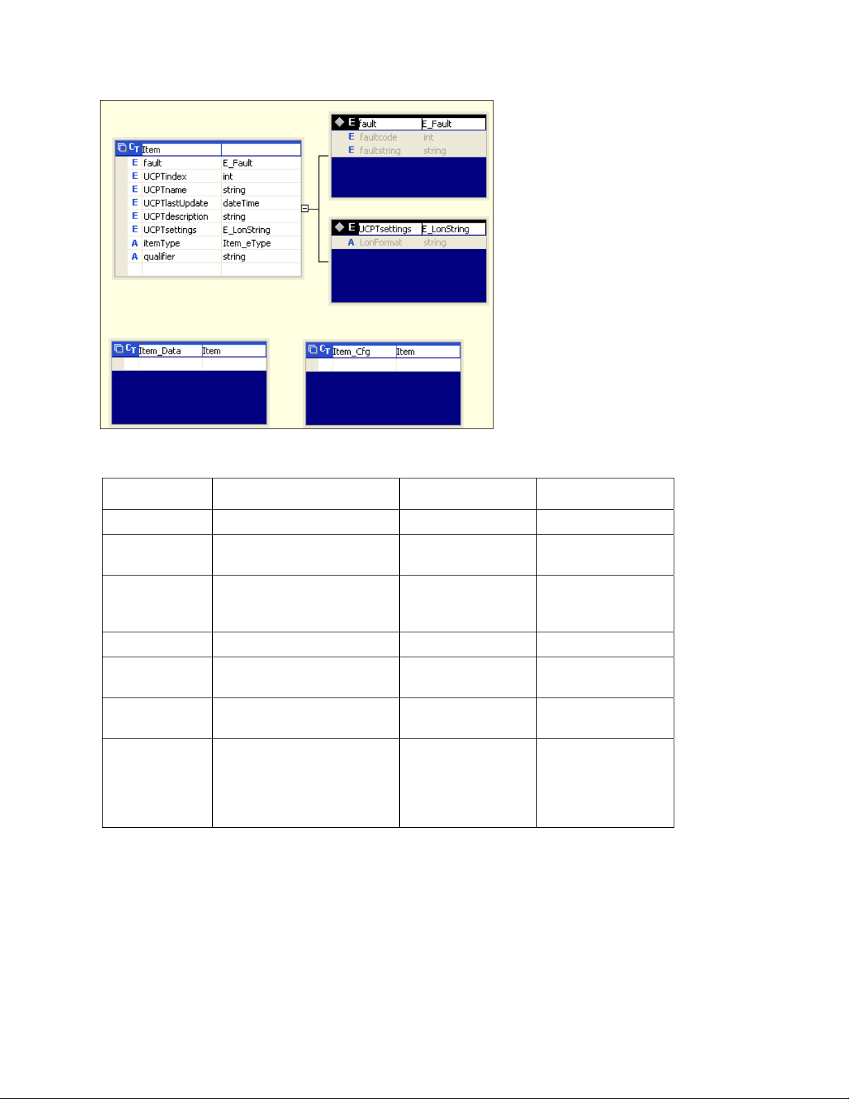
Item_Data and Item_Cfg inherit from Item
Because Item is the base class for all types passed in the Get /Set /Delete, Read /Write, and Invoke
functions, you can pass any kind of configuration or state information in the corresponding message.
Message Name Description Request Object Response Object
List Retrieves a list of Items. xSelect Item_Coll
Get Retrieves the configuration of
items.
Set Creates items or overwrites
the configuration of existing
items.
Delete Deletes an item. Item_Coll Item_Coll
Read Reads the value and status of
items.
Write Writes values or states to
items.
Invoke Sends a network management
command to a L
device or calls special
functions on applications or
data points.
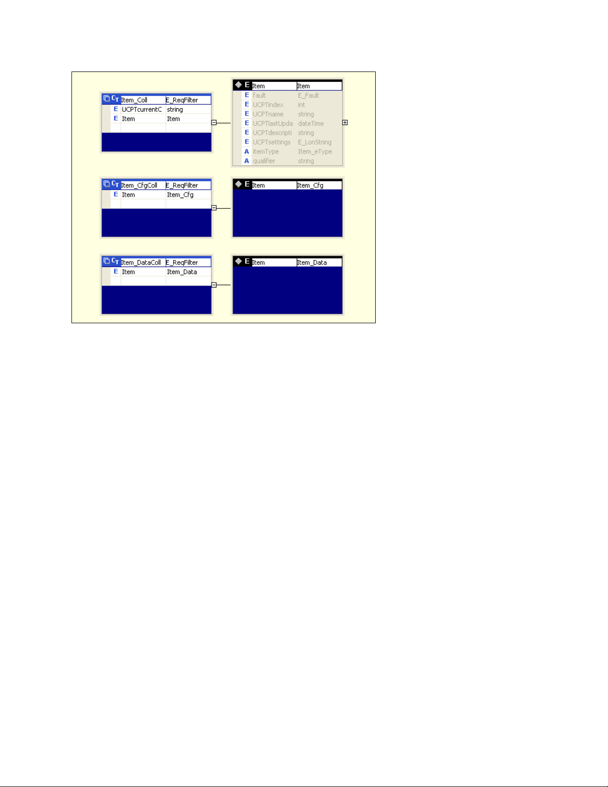
All requests for information (Read and Get, and Delete and Invoke messages) are called with Item_Coll
as the collection type. Item_Coll is a collection of Item and can thus contain any type (also Item_Cfg
and Item_Data).
ONWORKS
Item_Coll Item_CfgColl
Item_CfgColl Item_Coll
Item_Coll Item_DataColl
Item_DataColl Item_Coll
Item_Coll Item_Coll
The Set-Response and Get-Request messages use the Item_CfgColl, which is a collection of types
containing configuration data. The Read-Response and Write-Request messages use the
Item_DataColl collection, which is a collection of types containing dynamic data.
i.LON SmartServer 2.0 Programmer’s Reference
2-10
Page 25
Collection type Item type of
You can cast an item to a more specialized type using meta data (the xsi:type attribute) that is passed
along with the application data. The xsi:type attribute describes the actual type of an item and is
passed as an attribute of the <Item> element. If the sent type is the expected base type (Item, Item_Cfg
or, Item_Data), no xsi:type attribute is sent. For more information on xsi types, go to
www.w3.org/TR/xmlschema-1/#Instance_Document_Construction.
2.5.7
SOAP Message Attributes
Version 4.0 SOAP request messages support some attributes, and the response messages from the
SmartServer always contain all attributes. If the data type of an item is not the declared as a base type
in the SOAP request (Item, Item_Cfg, or Item_Data), the xsi:type attribute will be added to the item
instance. Note that you do not have to set the xsi:type attribute in a SOAP request if you are using a
SOAP framework like .NET or one of Java’s SOAP frameworks. This is because the xsi:type attribute
is part of the XML Schema specification, and it will be added automatically.
For more information on the xsi:type attribute, see the Version 4.0 XML schema type (iLON100.xsd),
which is installed in the L
computer when you install the SmartServer software.
2.5.8
Using xSelect Statements in SOAP Message Requests
You can use xSelect statements in List, Get, Read, and Delete messages to filter the items returned by
the function. The xSelect statement queries the item instances in a given data set and returns those
items meeting the specified criteria. The xSelect statement provides some of the functionality of the
xPath language defined by the W3C, except that you can compare strings to dates using compare
operators “<”, “>”, and “=”.
Each xSelect statement should specify an xsi (item) type. An xSelect statement may reference an item
identifier <UCPTname> and contain some predicates [predicate1] [ predicate2]. In any xSelect
statement, the predicates may include a <UCPTlastUpdate> expression and a position () expression.
Common predicates used include contains and starts-with.
The predicates are processed as a cascade of queries. For example, you could first use a
<UCPTlastUpdate> query to get the items that were updated during a specific time period and then
query items 10 to 20 returned by the first result using a position() expression.
ONWORKS\iLon100\images\iLon100 4. 0x\web\WSDL\v4.0 folder on your
i.LON SmartServer 2.0 Programmer’s Reference
2-11
Page 26

The following code samples demonstrate supported xSelect statements.
Example 1 – List or Get all channels on the SmartServer:
<iLonItem>
<xSelect> = "//Item[@xsi:type="Channel_Cfg"] </xSelect>
</iLonItem>
Example 2 – List or Get all LONWORKS channels on the SmartServer that were updated after a specific
time:
<iLonItem>
<xSelect>//Item[@xsi:type="LON_Channel_Cfg"][UCPTlastUpdate >"2008-04-01T00:00:00
</xSelect>
</iLonItem>
"]
Example 3 – List or Get all LONWORKS application devices of a specific type (by name) on a specific
channel.
<iLonItem>
<xSelect>//Item[@xsi:type="LON_Device_Cfg"][contains(UCPTname,"Net/LON/DIO")]</xSelect>
</iLonItem>
Example 4 – List or Get all instantiated functional blocks on the SmartServer automated systems
device [i.LON App (internal)]:
<iLonItem>
<xSelect>//Item[@xsi:type="Fb_Cfg"][starts-with(UCPTname,"Net/LON/")][UCPThidden=0]</xSelect>
</iLonItem>
Example 4 – List, Get, or Read all data points on the Digital Input 1 functional block on the internal
i.LON App device:
<iLonItem>
<xSelect>//Item[@xsi:type="Dp_Cfg"]
[starts-with(UCPTname, "Net/LON/iLON App/Digital Input 1/")]</xSelect>
</iLonItem>
Example 5 – Get all SNVT_switch data points on the SmartServer that were updated in the time line
defined by <UCPTlastUpdate>:
<iLonItem>
<xSelect>
//Item[@xsi:type="Dp_Cfg"][UCPTformatDescription="#0000000000000000[0].SNVT_switch"]
[UCPTlastUpdate >"2008-04-01T00:00:00" and UCPTlastUpdate <"2008-04-07T00:00:00"]
</xSelect>
</iLonItem>
Example 6 – List, Get, or Read the data points on the internal i.LON App device in the time line
defined by <UCPTlastUpdate> to return a maximum of the 11th to 29th data points:
<iLonItem>
<xSelect>//Item[@xsi:type="Dp_Cfg"] [starts-with(UCPTname,"Net/LON/iLON App/")]
[UCPTlastUpdate > "2008-04-01T15:30:21Z" and UCPTlastUpdate < "2008-04-08T15:30:21Z"]
[position()>10 and position()<30]
</xSelect>
</iLonItem>
Example 7 – List or Get all instantiated Alarm Generators on the internal i.LON App device;
<iLonItem>
<xSelect>//Item[@xsi:type="UFPTalarmGenerator_Cfg"]</xSelect>
</iLonItem>
Example 8 – Read the first 10 events scheduled in a Scheduler on the internal i.LON App device:
<iLonItem>
<xSelect>//Item[@xsi:type=”UFPTscheduler_Data”]
</xSelect>
</iLonItem>
i.LON SmartServer 2.0 Programmer’s Reference
[UCPTname="Net/LON/iLON App/Scheduler"]
[UCPTeventFilter="EF_SCHEDULE"][position()<10]"
2-12
Page 27

Example 9 – Select a formatter report:
xSelect = "//Item[@xsi:type=”TemplateManager_NVT_Cfg”][UCPTlanguage="enu"]
[UCPTname="#0000000000000000[0].standard"][position()>=0 and
position()<10]"
Notes:
• For List functions, you must include an xSelect statement in the SOAP message request.
• For Get, Delete, and Read functions, the xSelect statement in the SOAP message request is
optional.
o If a Get, Delete, or Read function is called only with an xSelect statement, the function returns
all items of the specified xsi type that meet the criteria specified in the xSelect statement.
o If a Get, Delete, or Read function is called with an xSelect statement and one or more item
instances, the xSelect statement is overlaid on the item instances. This means that the xSelect
statement is an and expression (not an or expression or an exclusive or expression).
• You can only filter for properties that are included in a message response (except for the
<UCPTlastUpdate> property, which you can always filter). In a List request of Dp_Cfg items
(data points on the Data Server) for example, you can filter on the <UCPTname> property, but
you cannot filter on the <UCPTformatDescription>. In a Get request of Dp_Cfg items, however,
you can filter on the <UCPTformatDescription> property because this property is returned in the
Get message response.
• The SmartServer can only process one item type (xsi:type) per SOAP message (e.g., only
Channel_Cfg, LON_Dp_Cfg, or UFPTalarmGenerator). This is also true for xSelect responses
(except for UCPTlastUpdate which is a special case), Set messages, and other SOAP commands.
The first item type specified is always the one returned in the response message.
• Not all properties can be filtered and not all filter combinations work.
2.5.8.1 xsi Types
The following section lists the common xsi (items) types that you will include in xSelect statements.
For a list of all the item types included in the SOAP interface, see the Version 4.0 XML schema type
(iLON100.xsd), which is installed in the L
folder on your computer when you install the SmartServer software
Driver Item xsi type
General (no Driver)
Network Network_Cfg
Channel Channel_Cfg
Device Device_Cfg
Functional Block Fb_Cfg
SmartServer Applications
Alarm Generator UFPTalarmGenerator_Cfg
Alarm Notifier UFPTalarmNotifier_Cfg
Analog Functional Block UFPTanalogFunctionBlock_Cfg
Calendar UFPTcalendar_Cfg
Data Logger UFPTdataLogger_Cfg
Digital Input UFPTdigitalInput_Cfg
Digital Ouput UFPTdigitalOutput_Cfg
Node Object UFPTnodeObject_Cfg
Pulse Counter UFPTpulseCounter_Cfg
Real-TimeClock UFPTrealTimeClock_Cfg
Scheduler UFPTscheduler_Cfg
ONWORKS\iLon100\images\iLon100 4.0x\web\WSDL\v4.0
i.LON SmartServer 2.0 Programmer’s Reference
2-13
Page 28

Driver Item xsi type
Type Translator UFPTtypeTranslator_Cfg
Type Translator Rule UFPTtypeTranslator_Rule_Cfg
Data Point (configuration) Dp_Cfg
Data Point (data) Dp_Data
Data Point Reset Priority Dp_ResetPrio_Invoke
LONWORKS Network LON_Network_Cfg
Channel LON_Channel_Cfg
Device LON_Device_Cfg
Router LON_Device_Router_Cfg
RNI LON_Device_RNI_Cfg
Functional Block LON_Fb_Cfg
Network Variable LON_Dp_Cfg
Configuration Property LON_Cp_Dp_Cfg
Configuration Property File LON_Cp_File_Cfg
Modbus Network MOD_Network_Cfg
Channel MOD_Channel_Cfg
Device MOD_Device_Cfg
Functional Block MOD_Fb_Cfg
Data Point MOD_Cp_Dp_Cfg
M_Bus Network MBS_Network_Cfg
Channel MBS_Channel_Cfg
Device MBS_Device_Cfg
Functional Block MBS_Fb_Cfg
Data Point MBS_Cp_Dp_Cfg
Virtual Network Virtual_Network_Cfg
Channel Virtual_Channel_Cfg
Device Virtual_Device_Cfg
Functional Block Virtual_Fb_Cfg
Data Point Virtual_Cp_Dp_Cfg
2.6
Data Point References
The SmartServer has a more abstract and flexible method for referencing data points on the
SmartServer’s embedded applications by their parent functional blocks. Primarily, the data point type
is not specified by the tag name (for example, the SNVT_alarm_2 output tag is obsolete). In Version
4.0, each functional block representing a Smart Ser ver embedded application has a collection of data
point references. The data point type is specified by the dpType attribute, and it is a reference to the
data point’s programmatic name as defined in the functional profile template. Some functional
blocks also extend the base data point reference XML type. In these cases, the <DataPoint> tag also
has an xsi:type attribute with the derived type.
The following code samples demonstrate how data points on the SmartServer’s embedded applications
are referenced. In the first example, the nvoAgAlarmFlag data point on an Alarm Generator functional
block is referenced. In the second example, the nvoDlLevAlarm data point on a Data Logger
functional block is referenced:
<DataPoint dpType="nvoAlarmFlag" discrim="dir_out">
<UCPTname>Net/LON/iLON App/Alarm Generator[0]/nvoAgAlarmFlag[0]</UCPTname>
<UCPTformatDescription>#0000000000000000[0].SNVT_switch</UCPTformatDescription>
</DataPoint>
i.LON SmartServer 2.0 Programmer’s Reference
2-14
Page 29

<DataPoint dpType="nvoLevelAlarm" discrim="dir_out">
<UCPTname>Net/LON/iLON App/Data Logger[0]/nvoDlLevAlarm[0]</UCPTname>
<UCPTformatDescription>#0000000000000000[0].SNVT_alarm</UCPTformatDescription>
</DataPoint>
2.7
UCPTcurrentConfig
Each application on the SmartServer stores the namespace version of the client that last set its
configuration (via a Set function) its last configuration. When a client sends a List function in a SOAP
request, the SOAP response returns the UCPTcurrentConfig tag, which contains this information. The
client should check this tag because new namespaces may contain new or different tags that older
clients will not understand.
If a SmartServer responds with a newer UCPTcurrentConfig, the client should allow the user either to
continue using the older tool with the risk that it may overwrite changes made with a newer tool, or fail
and preserve the configuration created by the new tool.
The following code demonstrates the UCPTcurrentConfig tag returned by a SOAP response after
receiving a List function in a SOAP request.
<UCPTcurrentConfig>4.0</UCPTcurrentConfig>
2.8
Fault Structure
The faultcode and faultstring are now combined in a fault structure. If a fault structure exists, both the
faultcode and faultstring elements exist. This enables a client to check only for the existence of a fault
structure instead of having to check for both elements.
The following code demonstrates the fault structure used in Version 4.0.
<fault>
<faultcode faultType="_error">4</faultcode>
<faultstring xml:lang="en-US">fault string</faultstring>
</fault>
2.9
LonString type
The Version 4.0 XML schema declares the type E_LonString, which is a string type and has a value
that represents a L
string that contains the format description of the item. The WSDL uses the E_LonString type for
enumerations or element values that have format descriptions that depend on references to other data
point formats.
The following code sample demonstrates the LonFormat attribute of the E_LonStri n g type.
<UCPTvalue LonFormat="#0000000000000000[0].SNVT_switch">100.0 1</UCPTvalue>
<UCPTvalue LonFormat="#0000000000000000[0].SNVT_switch.value">100.0</UCPTvalue>
<UCPTvalue LonFormat="#0000000000000000[0].SNVT_switch.state">1</UCPTvalue>
<UCPTvalue LonFormat="UCPTvalueDef">ON</UCPTvalue>
<UCPTpointStatus LonFormat="UCPTpointStatus">AL_NUL</UCPTpointStatus>
When you use the Read function on a data point on the Data Server (xsi type = Dp_Cfg), the
E_LonString type has a unit attribute that specifies the unit strings defined for the data point.
<UCPTvalue LonFormat="#0000000000000000[0].SNVT_switch" Unit="value, state ">0.0 0</UCPTvalue>
2.10
SOAP Message Examples
ONWORKS value. The E_LonString also contains the LonFormat attribute which is a
The following examples demonstrate how to use the Version 4.0 SOAP interface to get the
configuration of data point, write a value to a data point in a Web connection, and read the data in a
data logger.
i.LON SmartServer 2.0 Programmer’s Reference
2-15
Page 30

2.10.1
Configuration Data
The following example demonstrates how to use a Get function to obtain the configuration of a data
point on the Data Server (Dp_Cfg) using the unique <UCPTname> of the data point.
Request Message
<?xml version='1.0' encoding='utf-8'?>
<SOAP-ENV:Envelope SOAP-ENV:encodingStyle="http://schemas.xmlsoap.org/soap/encoding/"
xmlns:SOAP-ENV="http://schemas.xmlsoap.org/soap/envelope/"
xmlns:xsi="http://www.w3.org/2001/XMLSchema-instance">
<SOAP-ENV:Header>
<p:messageProperties xmlns:p="http://wsdl.echelon.com/web_services_ns/ilon100/v4.0/message/">
<p:UCPTtimeStamp>2008-04-08T11:37:32.156-07:00</p:UCPTtimeStamp>
<p:UCPTuniqueId>0300000A5BF2</p:UCPTuniqueId>
<p:UCPTipAddress>10.2.124.53</p:UCPTipAddress>
<p:UCPTport>80</p:UCPTport>
<p:UCPTlastUpdate>2008-04-08T18:22:52Z</p:UCPTlastUpdate>
<p:UCPTprocessingTime>20</p:UCPTprocessingTime>
</p:messageProperties></SOAP-ENV:Header>
<SOAP-ENV:Body>
<Get xmlns="http://wsdl.echelon.com/web_services_ns/ilon100/v4.0/message/">
<iLonItem>
<Item xsi:type="Dp_Cfg">
<UCPTname>Net/LON/iLON App/VirtFb/nviSwitch_3</UCPTname>
</Item>
</iLonItem>
</Get>
</SOAP-ENV:Body>
</SOAP-ENV:Envelope>
Response Message
<?xml version="1.0" encoding="utf-8" ?>
<SOAP-ENV:Envelope SOAP-ENV:encodingStyle="http://schemas.xmlsoap.org/soap/encoding/"
xmlns:SOAP-ENV="http://schemas.xmlsoap.org/soap/envelope/"
xmlns:xsi="http://www.w3.org/2001/XMLSchema-instance"
xmlns:xsd="http://www.w3.org/2001/XMLSchema"><SOAP-ENV:Header>
<p:messageProperties xmlns:p="http://wsdl.echelon.com/web_services_ns/ilon100/v4.0/message/">
<p:UCPTtimeStamp>2008-04-08T11:56:41.116-07:00</p:UCPTtimeStamp>
<p:UCPTuniqueId>0300000A5BF2</p:UCPTuniqueId>
<p:UCPTipAddress>10.2.124.53</p:UCPTipAddress>
<p:UCPTport>80</p:UCPTport>
<p:UCPTlastUpdate>2008-04-08T18:22:52Z</p:UCPTlastUpdate>
<p:UCPTprocessingTime>46</p:UCPTprocessingTime>
</p:messageProperties>
</SOAP-ENV:Header>
<SOAP-ENV:Body>
<GetResponse xmlns="http://wsdl.echelon.com/web_services_ns/ilon100/v4.0/message/">
<iLonItem >
<UCPTfaultCount>0</UCPTfaultCount>
<Item xsi:type="Dp_Cfg" >
<UCPTname>Net/LON/iLON App/VirtFb/nviSwitch_3</UCPTname>
<UCPTannotation>Dp_In;xsi:type="LON_Dp_Cfg"</UCPTannotation>
<UCPThidden>0</UCPThidden>
<UCPTlastUpdate>2008-03-26T16:16:43.070-07:00</UCPTlastUpdate>
<UCPTformatDescription>#0000000000000000[0].SNVT_switch</UCPTformatDescription>
<UCPTlength>2</UCPTlength>
<UCPTdirection LonFormat="UCPTdirection" >DIR_IN</UCPTdirection>
<UCPTunit field="" >value, state</UCPTunit>
<UCPTunit field="value" >% of full level</UCPTunit>
<UCPTunit field="state" >state code</UCPTunit>
<UCPTbaseType LonFormat="UCPTbaseType" >BT_STRUCT</UCPTbaseType>
<UCPTmaxFields>2</UCPTmaxFields>
<SCPTmaxSendTime>0.0</SCPTmaxSendTime>
<SCPTminSendTime>0.0</SCPTminSendTime>
<SCPTmaxRcvTime>0.0</SCPTmaxRcvTime>
<ValueDef>
<UCPTindex>0</UCPTindex>
<UCPTname>OFF</UCPTname>
<UCPTvalue LonFormat="#0000000000000000[0].SNVT_switch" >0.0 0</UCPTvalue>
i.LON SmartServer 2.0 Programmer’s Reference
2-16
Page 31

</ValueDef>
<ValueDef>
<UCPTindex>1</UCPTindex>
<UCPTname>ON</UCPTname>
<UCPTvalue LonFormat="#0000000000000000[0].SNVT_switch" >100.0 1</UCPTvalue>
</ValueDef>
</Item>
</iLonItem>
</GetResponse>
</SOAP-ENV:Body>
</SOAP-ENV:Envelope>
2.10.2
Web Binding
You can use the WebBinder application on the SmartServer to send a SOAP message when a data
point update occurs. When the source data point (Dp_Data) in a Web connection is updated, the
SmartServer sends a Write request message for the transaction, and the response is sent by the receiver,
which may be another SmartServer, an LNS server, or a WebBinder Target (a Web server that can
process SOAP requests). The following example shows a Write message that is sent by a SmartServer
and is configured by the WebBinder application.
Request Message
<?xml version="1.0" encoding="utf-8" ?>
<SOAP-ENV:Envelope SOAP-ENV:encodingStyle="http://schemas.xmlsoap.org/soap/encoding/"
xmlns:SOAP-ENV="http://schemas.xmlsoap.org/soap/envelope/"
xmlns:xsi="http://www.w3.org/2001/XMLSchema-instance" xmlns:xsd="http://www.w3.org/2001/XMLSchema">
<SOAP-ENV:Header>
<p:messageProperties xmlns:p="http://wsdl.echelon.com/web_services_ns/ilon100/v4.0/message/">
<p:UCPTtimeStamp>2008-04-08T11:14:56.289-07:00</p:UCPTtimeStamp>
<p:UCPTuniqueId>0300000A5BF2</p:UCPTuniqueId>
<p:UCPTipAddress>10.2.124.53</p:UCPTipAddress>
<p:UCPTport>80</p:UCPTport>
<p:UCPTlastUpdate>2008-04-08T18:10:37Z</p:UCPTlastUpdate>
<p:UCPTprocessingTime>102</p:UCPTprocessingTime>
</p:messageProperties>
</SOAP-ENV:Header>
<SOAP-ENV:Body>
<Write xmlns="http://wsdl.echelon.com/web_services_ns/ilon100/v4.0/message/">
<iLonItem>
<UCPTfaultCount>0</UCPTfaultCount>
<Item xsi:type="Dp_Data">
<UCPTname>Net/LON/iLON App/Digital Input 1/nvoClsValue_1</UCPTname>
<UCPTannotation>Dp_Out;xsi:type="LON_Dp_Cfg"</UCPTannotation>
<UCPThidden>0</UCPThidden>
<UCPTaliasName>NVL_nvoClsValue_1</UCPTaliasName>
<UCPTlastUpdate>2008-04-08T11:14:53.599-07:00</UCPTlastUpdate>
<UCPTvalue LonFormat="#0000000000000000[0].SNVT_switch">0.0 0</UCPTvalue>
<UCPTvalue LonFormat="UCPTvalueDef">OFF</UCPTvalue>
<UCPTpointStatus LonFormat="UCPTpointStatus">AL_NO_CONDITION</UCPTpointStatus>
<UCPTpriority>255</UCPTpriority>
</Item>
</iLonItem>
</Write>
</SOAP-ENV:Body>
</SOAP-ENV:Envelope>
Response Message
<?xml version="1.0" encoding="utf-8" ?>
<SOAP-ENV:Envelope SOAP-ENV:encodingStyle="http://schemas.xmlsoap.org/soap/encoding/"
xmlns:SOAP-ENV="http://schemas.xmlsoap.org/soap/envelope/"
xmlns:xsi="http://www.w3.org/2001/XMLSchema-instance" xmlns:xsd="http://www.w3.org/2001/XMLSchema">
<SOAP-ENV:Header>
<p:messageProperties xmlns:p="http://wsdl.echelon.com/web_services_ns/ilon100/v4.0/message/">
<p:UCPTtimeStamp>2008-04-08T11:37:32.156-07:00</p:UCPTtimeStamp>
<p:UCPTuniqueId>0300000A5BF2</p:UCPTuniqueId>
<p:UCPTipAddress>10.2.124.53</p:UCPTipAddress>
<p:UCPTport>80</p:UCPTport>
<p:UCPTlastUpdate>2008-04-08T18:22:52Z</p:UCPTlastUpdate>
i.LON SmartServer 2.0 Programmer’s Reference
2-17
Page 32

<p:UCPTprocessingTime>20</p:UCPTprocessingTime>
</p:messageProperties>
</SOAP-ENV:Header>
<SOAP-ENV:Body>
<WriteResponse xmlns="http://wsdl.echelon.com/web_services_ns/ilon100/v4.0/message/">
<iLonItem >
<UCPTfaultCount>0</UCPTfaultCount>
<Item xsi:type="Dp_Data" >
<UCPTname>Net/LON/iLON App/Digital Input 1/nvoClsValue_1</UCPTname>
<UCPTannotation>Dp_Out;xsi:type="LON_Dp_Cfg"</UCPTannotation>
<UCPThidden>0</UCPThidden>
<UCPTaliasName>NVL_nvoClsValue_1</UCPTaliasName>
<UCPTvalue LonFormat="#0000000000000000[0].SNVT_switch" >100.0 1</UCPTvalue>
<UCPTvalue LonFormat="UCPTvalueDef" >ON</UCPTvalue>
</Item>
</iLonItem>
</WriteResponse>
</SOAP-ENV:Body>
</SOAP-ENV:Envelope>
2.10.3
Data Log Read
You can read the contents of the alarm logs and data logs stored on the SmartSever. The following
example demonstrates how to use the Read function to read the elements in a Data Log.
Request Message
<?xml version="1.0" encoding="utf-8" ?>
<SOAP-ENV:Envelope SOAP-ENV:encodingStyle="http://schemas.xmlsoap.org/soap/encoding/"
xmlns:SOAP-ENV="http://schemas.xmlsoap.org/soap/envelope/"
xmlns:xsi="http://www.w3.org/2001/XMLSchema-instance" xmlns:xsd="http://www.w3.org/2001/XMLSchema">
<SOAP-ENV:Header>
<p:messageProperties xmlns:p="http://wsdl.echelon.com/web_services_ns/ilon100/v4.0/message/">
<p:UCPTtimeStamp>2008-04-08T10:28:36.840-07:00</p:UCPTtimeStamp>
<p:UCPTuniqueId>0300000A5BF2</p:UCPTuniqueId>
<p:UCPTipAddress>10.2.124.53</p:UCPTipAddress>
<p:UCPTport>80</p:UCPTport>
<p:UCPTlastUpdate>2008-04-07T23:45:19Z</p:UCPTlastUpdate>
<p:UCPTprocessingTime>54</p:UCPTprocessingTime>
</p:messageProperties>
</SOAP-ENV:Header>
<SOAP-ENV:Body>
<Read xmlns="http://wsdl.echelon.com/web_services_ns/ilon100/v4.0/message/">
<iLonItem>
<xSelect>//Item [@xsi:type="UFPTdataLogger_Data"]
[UCPTlastUpdate > "2008-04-08T00:00:00.000"
and UCPTlastUpdate <= "2008-04-08T12:00:00.000"]
[position()< 3]
</xSelect>
<Item>
<UCPTname>Net/LON/iLON App/Data Logger[0]</UCPTname>
</Item>
</iLonItem>
</Read>
</SOAP-ENV:Body>
</SOAP-ENV:Envelope>
Response Message
<?xml version="1.0" encoding="utf-8" ?>
<SOAP-ENV:Envelope SOAP-ENV:encodingStyle="http://schemas.xmlsoap.org/soap/encoding/"
xmlns:SOAP-ENV="http://schemas.xmlsoap.org/soap/envelope/"
xmlns:xsi="http://www.w3.org/2001/XMLSchema-instance"
xmlns:xsd="http://www.w3.org/2001/XMLSchema"><SOAP-ENV:Header>
<p:messageProperties xmlns:p="http://wsdl.echelon.com/web_services_ns/ilon100/v4.0/message/">
<p:UCPTtimeStamp>2008-04-08T11:30:31.272-07:00</p:UCPTtimeStamp>
<p:UCPTuniqueId>0300000A5BF2</p:UCPTuniqueId>
<p:UCPTipAddress>10.2.124.53</p:UCPTipAddress>
<p:UCPTport>80</p:UCPTport>
<p:UCPTlastUpdate>2008-04-08T18:22:52Z</p:UCPTlastUpdate>
<p:UCPTprocessingTime>83</p:UCPTprocessingTime>
i.LON SmartServer 2.0 Programmer’s Reference
2-18
Page 33

</p:messageProperties>
</SOAP-ENV:Header>
<SOAP-ENV:Body>
<ReadResponse xmlns="http://wsdl.echelon.com/web_services_ns/ilon100/v4.0/message/">
<iLonItem >
<UCPTfaultCount>0</UCPTfaultCount>
<Item xsi:type="UFPTdataLogger_Meta_Data" >
<UCPTname>Net/LON/iLON App/Data Logger[0]</UCPTname>
<UCPTlastUpdate>2008-04-08T11:30:00.062-07:00</UCPTlastUpdate>
<UCPTstart>2008-04-08T11:22:42.762-07:00</UCPTstart>
<UCPTstop>2008-04-08T11:30:00.062-07:00</UCPTstop>
<UCPTmodificationNumber>0</UCPTmodificationNumber>
<UCPTlogLevel>8.778</UCPTlogLevel>
<UCPTtotalCount>59</UCPTtotalCount>
</Item>
<Item xsi:type="UFPTdataLogger_Data" >
<UCPTname>Net/LON/iLON App/Digital Input 1/nvoClsValue_1</UCPTname>
<UCPTaliasName>NVL_nvoClsValue_1</UCPTaliasName>
<UCPTlastUpdate>2008-04-08T11:22:42.762-07:00</UCPTlastUpdate>
<UCPTvalue LonFormat="#0000000000000000[0].SNVT_switch">0.0 0</UCPTvalue>
<UCPTvalue LonFormat="UCPTvalueDef">OFF</UCPTvalue>
<UCPTpointStatus LonFormat="UCPTpointStatus">AL_NO_CONDITION</UCPTpointStatus>
<UCPTpriority>255</UCPTpriority>
<UCPTmetaDataPath>//*[@xsi:type=“UFPTdataLogger_Meta_Data”]
[UCPTname=“Net/LON/iLON App/Data Logger[0]”]
</UCPTmetaDataPath>
</Item>
<Item xsi:type="UFPTdataLogger_Data" >
<UCPTname>Net/LON/iLON App/Digital Input 1/nvoClsValue_1</UCPTname>
<UCPTaliasName>NVL_nvoClsValue_1</UCPTaliasName>
<UCPTlastUpdate>2008-04-08T11:22:52.952-07:00</UCPTlastUpdate>
<UCPTvalue LonFormat="#0000000000000000[0].SNVT_switch">0.0 0</UCPTvalue>
<UCPTvalue LonFormat="UCPTvalueDef">OFF</UCPTvalue>
<UCPTpointStatus LonFormat="UCPTpointStatus">AL_NO_CONDITION</UCPTpointStatus>
<UCPTpriority>255</UCPTpriority>
<UCPTmetaDataPath>//*[@xsi:type=“UFPTdataLogger_Meta_Data”]
[UCPTname=“Net/LON/iLON App/Data Logger[0]”]
</UCPTmetaDataPath>
</Item>
</iLonItem>
</Read>
</SOAP-ENV:Body>
</SOAP-ENV:Envelope>
i.LON SmartServer 2.0 Programmer’s Reference
2-19
Page 34

3 SmartServer Applications and the SOAP/XML
Interface
This chapter provides an overview of the applications supported by the SmartServer, and of how you
can use the SOAP/XML interface to configure these applications and use the data they generate. This
chapter includes the following major sections:
Overview of SmartServer Applications. This section provides a description of each of the
•
applications that the SmartServer supports.
•
SmartServer XML Configuration Files. The configuration of each SmartServer application is
stored in an XML file. This section lists those XML files, and it indicates where they are stored
on the SmartServer.
SmartServer Resource Files. The SmartServer resource files contain information you will need
•
when using the SOAP functions. This section describes how to use the resource files.
•
SOAP Functions. The SmartServer’s SOAP interface includes a generic set of List, Get, Set,
Read, Write, and Delete functions that can be used by the SmartServer applications. Together,
these functions make up a symmetric interface. This section provides an overview of how to use
these functions.
Performance Issues. This section lists performance issues you should consider when using the
•
SOAP/XML interface.
3.1
Overview of SmartServer Applications
You can use the SOAP/XML interface to configure the following SmartServer applications:
•
Data Server. The SmartServer’s internal Data Server is a software component that abstracts any
data element of any bus into a data point. This enables the SmartServer’s built-in applications and
your custom SmartServer Web pages to operate on these abstractions without regard of the device
driver (e.g., L
•
Web Binding. You can use the Web Binder application to create Web connections that allow
direct data exchange over a TCP/IP network between a SmartServer and another host device such
as a remote SmartServer, LNS Server, or a WebBinder Target Server (a Web server that can
process SOAP requests such as Apache or IIS).
Data Logging. You can configure the SmartServer to record updates to the data points on your
•
network by creating Data Loggers. Each Data Logger will have its own log file, which will
contain log entries for each of the updates to the data points it is monitoring. These logs can be
downloaded and read with the Internet File Transfer Protocol (FTP), or retrieved with the Read
function.
Alarming. You can configure the SmartServer to trigger alarms based on the values and statuses
•
of the data points in your control network. The SmartServer can be configured to update any data
point in the L
notifying recipients of the alarms and the conditions that triggered them. Alarms can be
configured to shut off automatically when certain conditions are met, or they can be configured to
require manual clearance. You will create Alarm Generators and Alarm Notifiers to manage these
alarming tasks.
ONWORKS, Modbus, M-Bus, Virtual, and Freely Programmable Module [FPM]).
ONWORKS network, log the conditions to one or more data logs, or send out emails
Analog Functional Blocks. You can use the Analog Functional Block application to perform
•
statistical operations on the values of any of the data points in your network.
•
Scheduling. You can use the SmartServer to create daily and weekly schedules, as well as
exception schedules and override schedules. These schedules can drive the inputs to data points
bound to any L
i.LON SmartServer 2.0 Programmer’s Reference
ONWORKS, M-Bus or Modbus device. You can create Schedulers and Calendars to
3-1
Page 35

manage these tasks. You can also create a Real-Time Cock to create events based on sunrise and
sundown times.
•
Type Translation. You can use the Type Translator application to translate data from one network
variable data type to another. You will need to create Type Translators, and optionally Type
Translator Rules, to translate your data.
3.2
SmartServer XML Configuration Files
The configuration of each SmartServer application is stored in an XML file. You will use the
following XML files to configure the applications of your SmartServer:
/root/config/network/<network>/<channel>/i.LON App||<device>/
#8000010128000000[4].UFPTdataLogger.xml
/root/config/network/<network>/<channel>/i.LON App||<device>/
#8000010128000000[4].UFPTalarmNotifier.xml
/root/config/network/<network>/<channel>/i.LON App||<device>/
#8000010128000000[4].UFPTalarmGenerator.xml
/root/config/network/<network>/<channel>/i.LON App||<device>/
#8000010128000000[4].UFPTanalogFunctionBlock.xml
/root/config/network/<network>/<channel>/i.LON App || <device>/
#8000010128000000[4].UFPTscheduler.xml
/root/config/network/<network>/<channel>/i.LON App || <device>/
#8000010128000000[4].UFPTcalendar.xml
/root/config/network/<network>/<channel>/i.LON App || <device>/
#8000010128000000[4].UFPTrealTimeClock.xml
/root/config/network/<network>/<channel>/i.LON App || <device>/
#8000010128000000[4].UFPTtypeTranslator.xml
The /root/config/software directory includes a sub-directory called TranslatorRules, which
contains several XML files you can use when configuring your Type Translators.
Note: The /root/config/software directory also contains a file called RNI.xml, which
contains configuration data used by the SmartServer remote network interface (RNI), and a file called
LSPA.xml, which contains configuration data used when the SmartServer connects to the
LonScanner
not manually edit the RNI.xml or LSPA.xml files. You can configure the RNI application using the
SmartServer Web pages. For more information on this, see the i.LON SmartSever User’s Guide. For
more information on the LonScanner Protocol Analyzer, see the LonScanner Protocol Analyzer User’s
Guide.
3.2.1
Each application includes a Set function. You can use the Set function to create and write to the XML
file for that application. The SmartServer will modify the XML file, and the operating parameters of
the associated application, each time it receives a Set message.
As an alternative to using SOAP, you can modify the files manually using an ASCII-text or XML
editor, and then download them to the SmartServer via FTP. Echelon does not recommend this, as you
will need to reboot the SmartServer for it to read the downloaded files, and the SmartServer will not
perform error-checking on the downloaded XML files.
i.LON SmartServer 2.0 Programmer’s Reference
™
Protocol Analyzer. There is no SOAP interface for these applications, and you should
Modifying the XML Configuration Files
3-2
Page 36

3.3
SmartServer Resource Files
There are many configuration properties you can configure with the SOAP functions described in this
document. This document provides a general description of each property, and other information you
will need when configuring each one, such as minimum and maximum values for scalar properties, and
maximum string lengths for string properties. This information is also contained in the SmartServer
resource files. In order to successfully send a SOAP message to the SmartServer, all data in the
message must be formatted as described in this document and in the resource files.
The SmartServer resource files are added to the LNS resource file catalog by the SmartServer software
installation utility, but they also exist locally on the SmartServer. In fact, like LNS, the SmartServer
maintains a catalog of resource files to use when formatting data in SOAP messages, network variable
updates, and web tag data from the SmartServer web server.
You can use the Node Builder Resource Editor, which is included on the SmartServer software
installation CD, to create new resource files for your own custom data point types and formats. Note
that when creating custom resource files on a PC, it is common to organize the files into subdirectories
such as:
C:\LonWorks\Types\User\YourCompany\YourResourceFiles.*
When adding these files to the SmartServer, it is the best practice to FTP them to a location on the
SmartServer flash disk matching the path on your computer:
/root/lonworks/types/User/YourCompnay/YourResourceFiles.*
You only need to FTP your own custom resource files to the SmartServer. If the name of your file set
is "MyResourceFiles", then you must copy every file which starts with the name "MyResourceFiles".
After you have copied these files to the SmartServer you must reboot to be able to use the new type
definitions and formats. During boot the SmartServer reads the resource files in this directory and
updates its local catalog accordingly.
3.3.1
Standard Network Variable Type (SNVT) Device Resource Files
SNVT device resource files describe the data structures within LonMark® SNVTs, and the formats
used to display SNVT data. On the SmartServer, you can find these files in the
/root/lonworks/types directory. They are named STANDARD.ENU, STANDARD.TYP,
STANDARD.FMT, and STANDARD.FPT.
The default format for a SNVT is its native format, as described in STANDARD.FMT. When you
add a data point to the SmartServer, you will assign that data point a format type. If a specific SNVT
format is desired for a particular data point, the <UCPTformatDescription> of that dat a point must be
set to the name of that SNVT format.
You can browse the entire SNVT device resource files online at
3.3.2
Standard Configuration Property Type (SCPT) Device Resource Files
This is a set of files that describes the data structures within SCPTs, and also describes the formats
used to display SCPT data. On the SmartServer, these files can be found in the directory
/root/lonworks/types directory. These files are named STANDARD.ENU,
STANDARD.TYP, STANDARD.FMT and STANDARD.FPT.
Many configuration properties that are used by the SmartServer applications are based on the SCPTs
defined in these files. The information provided in this document, and in the SCPT resource files, will
help you determine what values to assign to the SCPTs referenced by the SmartServer.
http://types.lonmark.org.
You can browse the entire SCPT device resource files online at
i.LON SmartServer 2.0 Programmer’s Reference
3-3
http://types.lonmark.org.
Page 37

3.3.3
User-Defined Network Variable Type (UNVT) Device Resource Files
Device manufacturers create UNVT device resource files to describe no n -st an dar d, manufacturer
specific network variables. Using the same mechanisms as the standard resource files, these files
describe how to format data from a particular manufacturer's device. On the SmartServer, you can find
all device resource files in the /root/lonworks/types directory.
To specify UNVT formats a fully qualified format name is required as follows:
#<progID>[<selector>].<format name>
In this syntax, the “#”, “[“, “]” and “.” characters are literal characters. A hex byte string (in the
“RAW_HEX_PACKED” format described below) represents the program ID. The selector is a one-digit
string. It represents a filter that indicates relevant parts of the program ID, and may be one of the
following:
0 - Standard
1 - Device Class
2 - Device Class and Usage
3 - Manufacturer
4 - Manufacturer and Device Class
5 - Manufacturer, Device Class, and Device Subclass
6 - Manufacturer, Device Class, Device Subclass, and Device Model
The format name syntax is similar to that used for SNVT types, except that the type name starts with
“UNVT” instead of “SNVT”. For example:
#800001128000000[4].UNVT_date_event
3.3.4
User-Defined Configuration Property Type (UCPT) Device Resource
Files
This is a set of files that describes the data structures within UCPTs and also describes the formats
used to display UCPT data. On the SmartServer, these files may be found in the
/root/lonworks/types directory. The files are named BAS_Controller.ENU,
BAS_Controller.TYP, BAS_Controller.FMT and BAS_Controller.FPT.
Echelon added these UCPTs for configuration properties used by SmartServer applications that have
no SCPT definition. You can browse the UCPT resource files online at
3.3.5
Data Point Templates
There is a set of data point templates in the root/config/template/lonworks/Dp directory that provide
the default configurations for new instances of specific data point types. These XML files contain the
default presets and the default heartbeat, throttle, and offline configuration properties for a number of
common data types, including SNVT_switch, SNVT_occupancy, SNVT_temp (incl u ding #SI and
#US formats), and SNVT_temp_f (including #SI and #US formats). This is very useful for working
with the data points of the external devices that you may add to the SmartServer.
3.3.6
Data Formatting
In order to keep the SOAP/XML interface neutral across regions, most of the rules for formatting data,
which would normally be changeable in LNS, are not changeable on the SmartServer. The one
exception is the support of measurement system locale, which was introduced in version 1.1 of the
SOAP/XML interface. The following list describes the various regional settings used by the
SmartServer SOAP / XML interface:
http://types.echelon.com.
Decimal Symbol – Always period "."
i.LON SmartServer 2.0 Programmer’s Reference
3-4
Page 38

Precision – Single floats always use 7 digits of precision, including digits before and after the decimal
point. Double floats always use 14 digits of precision. For the rest of the base types, precision is
determined by the type definition
Digit Grouping Symbol – Always com m a ","
Digit Grouping – Always in the form "123,456,789"
Negative Sign Symbol – Always the minus sign "-"
Negative Number Format – Always "-1.1"; negative symbol in front, and no space between the
symbol and the number
List Separators – If the format uses the localized list separator symbol vertical bar "|", the i.LON
SmartServer will replace it with comma ",". However, if you define a new type in the NodeBuilder
Resource Editor which is a structure, array or union, the default list separator is space " ". The
localized list separator must be explicitly specified in the format.
Measurement System – The SmartServer does not use localization settings for measurement system.
The measurement system used to display a formatted value is determined by the
UCPTformatDescription property of the data point. For example, if you have a data point whose
format is defined as SNVT_temp_f#US, then the UCPTvalue written to a data point Read function will
be in Fahrenheit.
If that data point is an input to the Alarm Generator, then the format of a property which specifies a
comparison value, a delta, or an offset like UCPThighLimit2Offset will also be in US units when you
read it with a Get function. Furthermore, you would have to use US units when setting the property
with a Set function.
You should note that the value stored in the XML file will always be in SI units so that XML files may
be shared between SmartServers. The rule used by the applications is that the format of the primary
data point for the application instance determines the format of measurement system dependent
properties, like offsets, comparison values and deltas.
3.4
SOAP Functions
The SOAP interface includes a generic set of List, Get, Set, and Delete functi ons t hat can be used by
the SmartServer applications. Together, these functions make up a symmetric interface. You can use
the response from the List function as the input to the Get function. You can use the response from the
Get function as the input to the Set function.
The SOAP interface also includes Read and Write methods that can be use to read and write values to
the data points on the Data Server, read entries in a data log, alarm log, or scheduler or calendar event
log, and update entries in an alarm log. The Read and Write functions also provide a symmetric
interface. You can use the output from the Read function as the basis for your input to the Write
function.
This section provides an overview of the functions in the SOAP interface, and it briefly describes how
you can use them.
3.4.1
List Functions
Use the List function to retrieve the names of the application instances or items of a specific type on
the SmartServer. For example, the List function can return a list containing the names of the Alarm
Generators, Data Loggers, Schedulers, or other functional bl oc ks rep resenting the SmartServer’s
embedded applications that have been instantiated. Similarly, you can use the List function to return a
list of the data points on the Data Server (Dp_Cfg) , or ret rieve a list of the channels (Channel_Cfg), the
ONWORKS application devices (LON_Device_Cfg), the Modbus devices (MOD_Device_Cfg), and
L
other network items on the SmartServer.
i.LON SmartServer 2.0 Programmer’s Reference
3-5
Page 39

3.4.2
Get Functions
You can use the Get function to retrieve the configuration of any application instance or item that you
have added to the SmartServer. For example, you could use the Get function to retrieve the
configurations of the Alarm Generators, Data Loggers, Schedulers, and other application instances that
have been added to the SmartServer. Similarly, you could use the Get function to retrieve the
configurations of the data points on the Data Server (D p_Cfg), or retrieve the L
devices (LON_Device_Cfg), the Modbus devices (MOD_Device_Cfg), and other network items on the
SmartServer. Note that you must reference the item whose configuration is to be retrieved by its
<UCPTname>.
Consider a scenario where you have used a List function to retrieve a list containing the <UCPTname>
of each Alarm Generator that has been added to the SmartServer. You could use the list as the input
for the Get function. The Get function would return the configuration of all the Alarm Generators
included in the list. You can also use the Get function to retrieve the configuration of a single Alarm
Generator, by supplying the <UCPTname> of the Alarm Generator functional block as the input.
3.4.3
Set Functions
You can use the Set function to write to each of the XML files described in the previous section.
When you invoke the Set function for an application for the first time, the associated XML file will be
created in the root/config/network/<network>/<channel>/iLONApp ||<device> directory on the
SmartServer, if it has not already been created. All data defined in the input supplied to the function
will be added to the XML file. Following this, you can use the Set function to add more data to the
XML file or to overwrite existing data.
ONWORKS application
For example, the first time an application invokes the Set function to create an Alarm Generator
functional block, the #8000010128000000[4].UFPTalarmGenerator.xml will be created in the
root/config/network/<network>/<channel>/iLONApp ||<device> directory of the SmartServer (if it
does not already exist based on the creation of another alarm generator functional block instance).
The file will contain an element for each Alarm Generator defined in the input passed to the function.
After its initial invocation, you can use Set function to overwrite the values of the properties defined
for the Alarm Generator application. You can also use it to add new Alarm Generators to the XML
file, or to overwrite the configuration of existing Alarm Generators.
When using the Set function to create an item such as an Alarm Generator, you should consider using
output supplied by the correspondi n g Get function as the basis for your input. The following
procedure describes how you might do so using the Alarm Generator functions. You could use this
algorithm when programming any of the SmartServer applications.
1. Invoke the List function to generate a list of Alarm Generators that have been added to the
SmartServer. This list includes the <UCPTname> of each Alarm Generator.
2. Invoke the Get function, using the list returned by the List function as the input. The function will
return the configuration of each Alarm Generator included in the list output.
3. Review the output from step 2, and choose an Alarm Generator to serve as your “default” Alarm
Generator. The Get output for this Alarm Generator will serve as the basis for the next Alarm
Generator you create. Modify the values of each property in the response returned by Get to
match the configuration you want for the new Alarm Generator. This will be more efficient than
building the input for the Set function from scratch.
Note: You must change the <UCPTname> of the Alarm Generator when using this algorithm.
Otherwise, the next step of this procedure will overwrite the configuration of the default Alarm
Generator you have chosen.
4. Invoke the Set function, using the modified response from Step 3 as input. The new item is
successfully created, without recreating an input that defines an entire Alarm Generator
configuration from scratch, and with minimal risk of format errors. Chapters 4-12 will clarify the
benefits of this algorithm.
i.LON SmartServer 2.0 Programmer’s Reference
3-6
Page 40

3.4.4
Read Functions
You can use the Read function to read the value, status, or priority of a data point on the Data Server
(Dp_Cfg), read the entries in an alarm log or data log, and read the events scheduled in a Scheduler or
Calendar. To use the Read function, you need to provide the <UCPTname> of the item to be read.
This could be a data point, or an Alarm Notifier, Data Logger, Scheduler, or Calendar functional block.
The Read function returns a list of <Item> elements of a Dp_Data type for each data point referenced
by the input you supplied to the function.
3.4.5
Write Functions
You can use the Write function to update the value, priority, or status of a data point on the Data Server
or to update an entry in an Alarm Log. To use the Write function, you need to provide an <Item>
element of a Dp_Data type that includes the <UCPTname> of the item to be updated, which could be a
data point or an Alarm Notifier functional block. When using the Write function, you can use the
output supplied by the correspondi n g Read function as the basis for your input.
3.4.6
Delete Functions
Use the Delete functions to delete items from an application. For example, you can use the Delete
function to delete an Alarm Generator functional block or to delete a data point on Data Logger. To
delete an item, you must provide an <Item> element of a specific xsi:type (corresponding to the item’s
driver) that includes the <UCPTname> of the item to be deleted.
3.5
Performance Issues
The SmartServer contains 64 MB of RAM, which allows for complicated application configurations
and extensive network use. However, even with this amount of memory, it is still possible for very
high levels of network traffic to the SmartServer, especially using the SOAP interface, to eventually
exhaust its memory. This could result in delays in network access of the SmartServer, performance
problems for the SmartServer applications, or in the worst case even a reboot of the SmartServer.
If your SmartServer exhibits some of these symptoms, you should cons ider reducing the level of
network traffic to it. The following numbers are guidelines that apply to the use of the SmartServer’s
SOAP interface. While they are not absolute limits or guarantees of performance, they may be helpful
to follow when attempting to manage the SmartServer’s network traffic load or troubleshoot a
performance problem.
As a result, you should follow these guidelines when programming SOAP applications:
• Limit the number of data points referenced in a single Get or Read message to no more than 100.
• Limit the number of alarm log records read in a single message to no more than 100. For more
information on reading alarm log records, see
• Limit the number of data log records read in a single message to no more than 150. For more
information on reading data log records, see
• If the combined XML file sizes for a given application exceed 100 KB, do not try to read all the
configuration data for that application in a single Get message. This could potentially happen with
the Scheduler application if all of its functional blocks were used, or possibly with the Alarm
Notifier application.
Chapter 7.
Chapter 5.
• Do not send a request message larger than 100 KB. Some possible examples of this might be
using a single Set message to define more than 100 data points or write to 40 Alarm Notifiers.
• Limit the number of simultaneous SOAP clients to no more than the number of Web tasks
specified in the WebParams.dat file on the SmartServer, which is eight. Also note that you
should not open more than two or three Web browsers for a given SmartServer.
i.LON SmartServer 2.0 Programmer’s Reference
3-7
Page 41

i.LON SmartServer 2.0 Programmer’s Reference
3-8
Page 42

4 Using the SmartServer Data Server
The SmartServer’s internal Data Server is a software component that abstracts any data element of any
bus into a data point. This enables the SmartServer’s built-in applications and your custom
SmartServer Web pages to operate on these abstractions wit ho ut regard of the device driver (e.g.,
ONWORKS, Modbus, M-Bus, Virtual, and Freely Programmable Module [FPM]).
L
Data points provide the SmartServer applications and Web server with a generic, open way to handle
any piece of information in any type of network, such as the current value of a network variable in an
LNS-managed network, or an explicit message in a closed L
handles all the details of these data point that are required by the various applications of the
SmartServer, such as how often a data point should be polled, its default value, its heartbeat, its current
status, and its current value.
At the Data Server layer, all data points have the same set of properties, regardless of the network or
device to which each data point is local. This is made possible by the drivers that exist for each data
point type, which handle communication between the Data Server and the physical network to which
each data point is local.
You can use a standard network management tool for the particular data point type to configure each
driver on the SmartServer. For example, you could use an LNS-based network management tool to
configure the data points on the SmartServer’s internal automated systems device (i.LON App). This
layer of abstraction between the drivers and the Data Server provides a mechanism for all SmartServer
applications to use data points of all types in the same way. The Data Server also ensures that the
configuration, status and value of each data point recognized by the tools you can use to configure the
SmartServer remain synchronized with each other, and within the device to which the data point is
local. The tools you can use to configure the SmartServer include custom SOAP applications, the
LonMaker tool, built-in SmartServer Web pages, and custom SmartServer Web pages.
ONWORKS system. The Data Server
The data elements that that can be abstracted by the Data Server include the following:
• The network variables and configuration properties on the SmartServer’s LON driver, which
include the following:
o The network variables and configuration properties on the SmartServer’s internal automated
systems device (Net/LON/i.LON App). The i.LON App device contains functional blocks
representing the SmartServer’s built-in applications. These data points were referred to as
NVLs in Version 3.0.
o The network variables and configuration properties of the L
the SmartServer. These data points were referred to as NVEs in Version 3.0.
o The system network variables on the SmartServer that maintain constant values for the
SmartServer’s built-in applications (e.g., Net/LON/iLON App/Alarm
Generator[0]/CompareDP). These data points were referred to as NVCs in Version 3.0.
• The registers of M-Bus and Modbus devices on the SmartServer’s M-Bus and Modbus drivers.
• The network variables on the SmartServer’s Virt ual driver. This includes the network variables of
the SmartServer’s internal systems device (Net/VirtCh/i.LON System), which contain connection
manager and LonTalk statistics, and the network variables on Interoperable Self-Installation (ISI)
devices connected to the SmartServer. These data points were referred to as NVVs in Version 3.0.
• The network variables and configuration properties on custom FPM drivers created with the
i.LON SmartServer Programming Tools. You can use FPM drivers as gateways to legacy
systems or nonnative networks such as BACnet and CAN (requires an external interface, sold
separately)
Programming Tools User’s Guide.
. For more information on creating FPM drivers, see the i.LON SmartServer
ONWORKS devices connected to
The following figure shows the relationship between the buses supported by the SmartServer, the Data
Server, and the SmartServer’s built-in applications.
i.LON SmartServer 2.0 Programmer’s Reference
4-1
Page 43

Two of the most important properties in the Data Server for any data point are the <UCPTpointStatus>
and <UCPTvalue> properties. The <UCPTpointStatus> property represents the current status of the
data point. The <UCPTvalue> property represents the current value of the data point. The Data Server
updates these properties in real time, and they are very useful to many SmartServer applications.
For example, you could set up an Alarm Generator that will update the <UCPTpointStatus> of a data
point to an alarm condition each time the <UCPTvalue> of that data point reaches a certain level. You
could then set up an Alarm Notifier that will send out an alarm notification each time the
<UCPTpointStatus> of the data point is updated to that condition. These applications are described in
more detail later in this document.
A data point list is generated for each data point when it is created and added to the Data Server. Once
you have created the data points for your SmartServer and added them to the Data Server, you can
reference these data points when using SmartServer applications such as the Analog Function Block,
Scheduler, Calendar, Type Translator, Alarm Generator, and Alarm Notifier. When any of these
applications reference a data point, that application is added to the data point list for the data point, and
the application will be notified each time the data point is updated. In this fashion, each application
has current access to all the network information pertaining to the data points it is using.
This chapter describes how to create data points and add them to the Data Server. Echelon
recommends that you restrict all networks to a maximum of 1,000 data points.
4.1
Creating and Modifying the Data Point XML Files
The SmartServer stores the data points on the Data Server in Dp.XML files under the parent
network/channel/device directory of the data points. Consider the following examples:
i.LON SmartServer 2.0 Programmer’s Reference
4-2
Page 44

• The data points on the SmartServer’s internal automated systems device (i.LON App), which
contains the functional blocks representing the SmartServer’s built-in applications, are stored in a
Dp.xml file in the root/config/network/Net/LON/iLONApp directory on the SmartServer flash
disk by default.
• The data points for an external L
ONWORKS digital input/output device connected to the
SmartServer might be stored in a Dp.xml file in the root/config/network/Net/LON/DIO-2
directory on the SmartServer flash disk.
• The data points on the SmartServer’s internal systems device (i.LON System), which contains
Interoperable Self-Installation (ISI) data points and data points containing connection manager and
LonTalk statistics, are stored in a Dp.xml file in the root/config/network/Net/VirtCh/iLONSystem
directory on the SmartServer flash disk.
• Note: The directories containing the Data Server’s Dp.xml files also contain separate
<driver>_Dp.xml files in which the data points’ driver properties are stored. The properties in
these files relate to a specific bus—L
ONWORKS, Modbus, M-Bus, Virtual, or FPM—and not the
Data Server. These driver-specific properties and how to use the List, Get, Set, and Delete
functions on them are described in Chapters 14–17.
You can manage the Dp.xml files manually using an XML text editor, and download them to the
root/config/network/<network>/<channel>/<device> directory of the SmartServer
via FTP. Echelon does not recommend this, as the SmartServer will require a reboot to read the
configuration of the downloaded XML files. Additionally, the SmartServer performs error checking
on all SOAP messages it receives before writing to the XML files. It will not perform error checking
on any XML files you download via FTP, and so the application may not boot properly.
However, if you plan to create or modify any XML files manually, you should review the rest of this
chapter first. This chapter describes the elements and properties in the Data Server configuration files
that define each data point’s configuration.
4.2
Overview of the Data Point XML File
The Dp.xml files on the SmartServer store the configurations of the data points that you have added to
the SmartServer under their respective parent network/channel/device directories. Each data point is
signified by an <Item> element of a Dp_Cfg type in the XML file. The configuration properties
contained in each <Item> element define the configuration of a data point, and are described later in
this chapter.
You can create new data points using the Set function, or by manually editing the Dp.xml file. You
can read the current value and status of a data point using the Read function, and you can write updated
values to data point using the Write function.
The following code represents a snippet of a sample Dp.xml file with one data point of an external
ONWORKS digital input/output device connected to the SmartServer:
L
<iLonItem>
<UCPTfaultCount>0</UCPTfaultCount>
<Item xsi:type="Dp_Cfg">
<UCPTname>Net/LON/DIO-3/Digital Output[0]/DO_Digital_1</UCPTname>
<UCPTannotation>Dp_In;xsi:type="LON_Dp_Cfg"</UCPTannotation>
<UCPThidden>0</UCPThidden>
<UCPTlastUpdate>2008-03-17T16:00:02.202-07:00</UCPTlastUpdate>
<UCPTdescription>Digital value to output</UCPTdescription>
<UCPTformatDescription>#0000000000000000[0].SNVT_switch</UCPTformatDescription>
<UCPTlength>2</UCPTlength>
<UCPTdirection LonFormat="UCPTdirection">DIR_IN</UCPTdirection>
<UCPTunit field="value">% of full level</UCPTunit>
<UCPTunit field="state">state code</UCPTunit>
<UCPTbaseType LonFormat="UCPTbaseType">BT_STRUCT</UCPTbaseType>
<UCPTmaxFields>2</UCPTmaxFields>
<SCPTmaxSendTime>0.0</SCPTmaxSendTime>
<SCPTmaxRcvTime>0.0</SCPTmaxRcvTime>
i.LON SmartServer 2.0 Programmer’s Reference
4-3
Page 45

<ValueDef>
<UCPTindex>0</UCPTindex>
<UCPTname>OFF</UCPTname>
<UCPTvalue LonFormat="#0000000000000000[0].SNVT_switch">0.0 0</UCPTvalue>
</ValueDef>
<ValueDef>
<UCPTindex>1</UCPTindex>
<UCPTname>ON</UCPTname>
<UCPTvalue LonFormat="#0000000000000000[0].SNVT_switch">100.0 1</UCPTvalue>
</ValueDef>
</Item>
</iLonItem>
4.3
Data Server SOAP Interface
You can use the SOAP interface to perform the following functions on a data point on the Data Server.
Function Description
List List the name of each data point that you have added to the Data
Server.
Get Retrieve the configuration of a data point.
Set Create a data point and add it to the Data Server, or modify the
configuration of an existing data point.
Read Read the current values, statuses, and priorities of one or more
data points.
Write Write to the current values, statuses, and priorities of one or more
data points.
Invoke Used with Dp_ResetPrio_Invoke xsi type to reset the priority
level assigned to a data point.
Delete Remove a data point from the Data Server.
Note: Section 21.1.1, Reading and Writing Data Point Values in Visual C# .NET, includes a C#.NET
programming example demonstrating how to use the Data Server SOAP interface to read and write
data point values. Section
21.2.1, Reading and Writing Data Point Va lues in Visual Basic.NET,
includes a Visual Basic .NET example demonstrating how to do this.
Section
22.3.1, Reading and Writing Data Point Values in Java, includes a Java example
demonstrating how to read and write data point value s .
4.3.1
Using the List Function on the Data Server
You can use the List function to retrieve a list of data points that have been added to the Data Server.
The List function takes an <iLonItem> element that has an xSelect statement querying items of a
Dp_Cfg type as its input, as shown in the example below. The List function returns an <Item> element
for each data point that you have added to Data Server.
Request (all data points on the Data Server)
<List xmlns="http://wsdl.echelon.com/web_services_ns/ilon100/v4.0/message/">
<iLonItem>
<xSelect>//Item[@xsi:type="Dp_Cfg"]</xSelect>
</iLonItem>
</List>
i.LON SmartServer 2.0 Programmer’s Reference
4-4
Page 46

You can use additional filters in the xSelect statement to return a specific set of data points on the Data
Server. These filters include the data point’s <UCPTname> and <UCPTlastUpdate> properties, and its
position on the data server.
Request (return all data points on the internal SmartServer automated systems device [i.LON
App])
<List xmlns="http://wsdl.echelon.com/web_services_ns/ilon100/v4.0/message/">
<iLonItem>
<xSelect>//Item[@xsi:type="Dp_Cfg"]
[starts-with(UCPTname,"Net/LON/iLON App")]
</xSelect>
</iLonItem>
</List>
Request (return the first 5 data points on the Net/LON/DIO-1/Digital Encoder functional block
that have been updated since 2008-03-17T00:00:00)
<List xmlns="http://wsdl.echelon.com/web_services_ns/ilon100/v4.0/message/">
<iLonItem>
<xSelect>//Item[@xsi:type="Dp_Cfg"][position()<5]
[starts-with(UCPTname,"Net/LON/DIO-1/Digital Encoder")]
[UCPTlastUpdate>"2008-03-17T00:00:00"]
</xSelect>
</iLonItem>
</List>
Response
<ListResponse xmlns="http://wsdl.echelon.com/web_services_ns/ilon100/v4.0/message/">
<iLonItem>
<UCPTfaultCount>0</UCPTfaultCount>
<UCPTcurrentConfig>4.0</UCPTcurrentConfig>
<Item>
<UCPTname>Net/LON/DIO-3/Digital Encoder[0]/DE_D1_1</UCPTname>
<UCPTannotation>Dp_In;xsi:type=“LON_Dp_Cfg”</UCPTannotation>
<UCPThidden>0</UCPThidden>
</Item>
<Item>
<UCPTname>Net/LON/DIO-3/Digital Encoder[1]/DE_D1_2</UCPTname>
<UCPTannotation>Dp_In;xsi:type=“LON_Dp_Cfg”</UCPTannotation>
<UCPThidden>0</UCPThidden>
</Item>
<Item>
<UCPTname>Net/LON/DIO-3/Digital Encoder[0]/DE_D2_1</UCPTname>
<UCPTannotation>Dp_In;xsi:type=“LON_Dp_Cfg”</UCPTannotation>
<UCPThidden>0</UCPThidden>
</Item>
<Item>
<UCPTname>Net/LON/DIO-3/Digital Encoder[1]/DE_D2_2</UCPTname>
<UCPTannotation>Dp_In;xsi:type=“LON_Dp_Cfg”</UCPTannotation>
<UCPThidden>0</UCPThidden>
</Item>
<Item>
<UCPTname>Net/LON/DIO-3/Digital Encoder[0]/DE_D3_1</UCPTname>
<UCPTannotation>Dp_In;xsi:type=“LON_Dp_Cfg”</UCPTannotation>
<UCPThidden>0</UCPThidden>
</Item>
</iLonItem>
</ListResponse>
4.3.2
Using the Get Function on the Data Server
You can use the Get function to retrieve the configuration of any data point that you have added to the
SmartServer’s Data Server. The input parameters you supply to the function will include one or more
<Item> elements. Each <Item> element includes a <UCPTname> property that you can use to specify
the data point to be returned, as well as any number of child elements you can use to identify the data
points whose configurations are to be returned.
i.LON SmartServer 2.0 Programmer’s Reference
4-5
Page 47

Alternatively, you can specify one or more data point properties such as <UCPTformatDescription>in
an xSelect statement to filter the items returned by the Get function.
Note: You should not attempt to retrieve the configuration of more than 100 data points with a single
call to the Get function.
Request (return all SNVT_switch data points on the internal SmartServer automated systems
device [i.LON App])
<List xmlns="http://wsdl.echelon.com/web_services_ns/ilon100/v4.0/message/">
<iLonItem>
<xSelect>//Item[@xsi:type="Dp_Cfg"]
[starts-with(UCPTname,"Net/LON/iLON App")]
[UCPTformatDescription="#0000000000000000[0].SNVT_switch"]
</xSelect>
</iLonItem>
</List>
Request (return a specific data point)
<Get xmlns="http://wsdl.echelon.com/web_services_ns/ilon100/v4.0/message/">
<iLonItem>
<Item>
<UCPTname>Net/LON/DIO-3/Digital Encoder[0]/DE_D1_1</UCPTname>
</Item>
</iLonItem>
</Get>
Response
<Get xmlns="http://wsdl.echelon.com/web_services_ns/ilon100/v4.0/message/">
<iLonItem>
<UCPTfaultCount>0</UCPTfaultCount>
<Item xsi:type="Dp_Cfg">
<UCPTname>Net/LON/DIO-3/Digital Encoder[0]/DE_D1_1</UCPTname>
<UCPTannotation>Dp_In;xsi:type="LON_Dp_Cfg"</UCPTannotation>
<UCPThidden>0</UCPThidden>
<UCPTlastUpdate>2008-03-17T13:36:48.460-07:00</UCPTlastUpdate>
<UCPTdescription>Digital encoder input 1. This is the least-significant
bit</UCPTdescription>
<UCPTformatDescription>#0000000000000000[0].SNVT_switch</UCPTformatDescription>
<UCPTlength>2</UCPTlength>
<UCPTdirection LonFormat="UCPTdirection">DIR_IN</UCPTdirection>
<UCPTunit field="value">% of full level</UCPTunit>
<UCPTunit field="state">state code</UCPTunit>
<UCPTbaseType LonFormat="UCPTbaseType">BT_STRUCT</UCPTbaseType>
<UCPTmaxFields>2</UCPTmaxFields>
<SCPTmaxSendTime>0.0</SCPTmaxSendTime>
<SCPTmaxRcvTime>0.0</SCPTmaxRcvTime>
<ValueDef>
<UCPTindex>0</UCPTindex>
<UCPTname>OFF</UCPTname>
<UCPTvalue LonFormat="#0000000000000000[0].SNVT_switch">0.0 0</UCPTvalue>
</ValueDef>
<ValueDef>
<UCPTindex>1</UCPTindex>
<UCPTname>ON</UCPTname>
<UCPTvalue LonFormat="#0000000000000000[0].SNVT_switch">100.0 1</UCPTvalue>
</ValueDef>
</Item>
<iLonItem>
The Get function returns an <Item> element for each data point referenced in the input parameters you
supplied to the function. The properties included within each <Item> element are initially defined
when the data point is added to the DataServer. You can write to these data point properties with the
Set function. The following table describes these properties.
i.LON SmartServer 2.0 Programmer’s Reference
4-6
Page 48

Property Description
<UCPTname>
<UCPTannotation>
<UCPThidden>
<UCPTlastUpdate>
The name of the data point in the following format:
<network/channel/device/functional block/d ata point>.
The direction of the data point (Dp_In, Dp_Out, or Dp_In_Out
[unspecified]), and its xsi type, which corresponds to the bus on
which the data point resides (e.g., LON_Dp_Cfg for a
ONWORKS data point) . This determines the icon used to
L
represent the data point in the navigation pane on the left side of
the SmartServer Web interface.
A flag indicating whether the data point is hidden or shown in
the navigation pane on the left side of the SmartServer Web
interface. This property may have the following values:
0 – shown
1 – hidden
A timestamp indicating the last time the configuration of the
data point was updated. This timestamp uses the ISO 8601
format, which is as follows:
YYYY-MM-DDTHH:MM:SS.sssZPhh:mm
The first segment of the time stamp (YYYY-MM-DD)
represents the date the configuration of the Data Point was last
updated. The second segment (after the T): HH:MM:SS.sss
represents the time of day the configuration of the Data Point
was last updated, in UTC (Coordinated Universal Time).
<UCPTdescription>
<UCPTformatDescription>
UTC is the current term for what was commonly referred to as
Greenwich Meridian Time (GMT). Zero (0) hours UTC is
midnight in Greenwich England, which lies on the zero
longitudinal meridian. Universal time is based on a 24-hour
clock; therefore, an afternoon hour such as 4 pm UTC would be
expressed as 16:00 UTC. The Z appended to the timestamp
indicates that it is in UTC. It can be left out.
For example, 2002-08-15T10:13:13Z indicates a UTC time of
10:13:13 AM on August 15, 2002.
If it is not UTC, time shift has to be defined:
2008-02-28T09:59:53.660+01:00
A user-defined description of the data point. This can be a
maximum of 201 characters long.
The data point's program ID; data type (SNVT, SCPT, UNVT,
UCPT, or built-in data type); and format (e.g., SI metric or US
customary if the type has multiple formats such as
SNVT_temp_p). The format description is displayed in the
following format:
#<manufacturer ID>[scope selector].<type name>[#format] .
This determines many factors about the data point, including the
type of values it takes and its base type. This could be any
i.LON SmartServer 2.0 Programmer’s Reference
4-7
Page 49

Property Description
standard (SNVT) format type included in the resource files on
the SmartServer, or any user-defined (UNVT) format type
included in resource files uploaded to the SmartServer. For
more information on the resource files, see
SmartServer
Resource Files.
If you do not set this property, it is set to RAW_HEX and the
data point uses raw hex values.
The SNVT format types included in the SmartServer resource
files are also listed and described in the SNVT Master List,
which can be downloaded from Echelon’s Support Web site at:
www.echelon.com
<UCPTlength>
<UCPTdirection>
<UCPTpersist>
<UCPTdefOutput>
<UCPTunit>
Specifies the size (in bytes) of the data point.
Specifies whether the data point is an input data point (DIR_IN),
output data point (DIR_OUT), or has an uns pecifi ed di rect i on
(DIR_NUL).
A flag indicating that the value stored in the data point persists
through SmartServer reboots. If this property is set to 1, the last
data point value is stored in the <UCPTdefOutput> property.
Configuration properties are marked as persistent by default.
Optional. The value to be assigned to this data point after a
power-up of the device or during an override of the functional
block.
For external data points and slave devices, Echelon does not
recommend that you define this property, as the value entered
here will be sent to the external device after a power-on.
Note: You can use the Set function to change this value in the
Data Server. However, you must program your application to
enforce the new value, as the SmartServer will continue to
enforce the default value taken from the resource files.
This property is a string up to 227 characters long that describes
the units the value in which a data point is measured. It is based
on the network variable type assigned to the data point. A
default value will be assigned to this property if a unit for the
network variable type chosen for the data point exists in the
resource files on the SmartServer.
For scalar and enumerated data points, this property specifies
the units of measures used by the data point. For example, the
unit string of a SNVT_temp_f data point is °F. The unit string
is defined by resource files.
For structured data points, the fields within the data point are
specified in a series of <UCPTunit> properties if the unit strings
can be edited. Using a SNVT_switch data point for example,
value and state fields will be specified in a series of
<UCPTunit> properties with their respective units of measure
(“% of full level” and “state code”). You can use the Set
i.LON SmartServer 2.0 Programmer’s Reference
4-8
Page 50

Property Description
function to edit the unit strings of data point fields.
<UCPTbaseType>
<UCPTmaxFields>
<SCPTmaxSendTime>
This read-only property is assigned to the data point
automatically, and is based on the point’s
<UCPTformatDescription>. It defines the base type of the data
point, as defined in the base_type_t enumeration in the
BAS_Controller resource files for the SmartServer.
This property specifies the maximum number of fields that the
data point may have. For scalar and enumerated data point this
property is 0 if the unit string cannot be edited, or it is 1 if the
unit string is editable.
For structured data points, this property is 2 or more based on
the SNVT or UNVT used by the data point. For example, the
default value in <UCPTmaxFields> for a SNVT_switch data
point will be 2 (value and state), and it will be 3 for a
SNVT_setting data point (function, setting, and rotation).
This property applies to output data points. It defines the
maximum amount of time that may elapse before the data point
is updated on the network, if it is set to a non-zero value.
For example, if a SNVT_temp value data point is changing by
one degree every 10 seconds and this property is set to two
seconds, the SmartServer will update the value of the data point
on the network every two seconds, even though the va lue of the
data point is not changing more than once every 10 seconds.
The receiver can use this output as a heartbeat. The receiver
will know something is wrong if he or she does not receive an
update every two seconds.
<SCPTminSendTime>
This property applies to output data points, and defines the
minimum amount of time that may elapse between data point
updates if it set to a non-zero value.
For example, if a SNVT_temp value data point is changing by
one degree every half second and this value is set to two
seconds, the data point will only be updated every two seconds
with the latest value, even though the value changes more
frequently than that.
<SCPTmaxRcvTime>
This property is used to control the maximum time that can
elapse after an update to a bound network input before another
update can occur. If this period elapses without an update, the
<UCPTpointStatus> of the data point will be updated to
AL_OFFLINE. You could create an Alarm Notifier to trigger
an alarm notification when this happens. For more information
on Alarm Notifiers, see Chapter 7,
The valid range for this property is any value between 0. 0 s ec
and 6,553.4 seconds. Setting <SCPTmaxRcvTime> to the
default value of 0.0 disables the receive failure mechanism.
<UCPTminValue>
Optional. This value is initially taken from the resource files, if
i.LON SmartServer 2.0 Programmer’s Reference
Alarm Notifier.
4-9
Page 51

Property Description
it exists for the data point type selected. This value represents
the minimum value the data point can be updated to.
Note: You can use the Set function to change this limit in the
Data Server. However, you must program your application to
enforce the new limit, as the SmartServer will continue to
enforce the limit taken from the resource files.
<UCPTmaxValue>
<UCPTinvalidValue>
<ValueDef>
Optional. This value is initially taken from the i.LON 100
resource files, if it exists for the data point type selected. This
value represents the maximum value the data point can be
updated to.
Note: You can use the Set function to change this limit in the
Data Server. However, you must program your application to
enforce the new limit, as the SmartServer will continue to
enforce the limit taken from the resource files.
Optional. The invalid value for the data point. If the data poi nt
is updated to this value, the <UCPTpointStatus> of the data
point will be set to AL_VALUE_INVALID. The status will be
returned to a normal condition (AL_NO_CONDITION) as soon
as the value is set to a valid value again. A default value will be
assigned to the <UCPTinvalidValue> property based on the
<UCPTformatDescription> selected, if an invalid value is
defined for the selected format in the resource files.
You could create an Alarm Notifier to trigger an alarm
notification when an invalid value is written to a data point and
the data point’s status is updated to AL_VALUE_INVALID.
For more information on Alarm Notifiers, see Chapter 7,
Notifier.
The <ValueDef> elements specify preset value definitions that
can be assigned to the data point. You can use these preset
values to update the value of the data point when other
SmartServer applications such as the Event Scheduler or the
Alarm Notifier reference them.
Alarm
Each <ValueDef> element includes three properties:
• <UCPTindex>. The index value assigned to the preset.
• <UCPTname>. The name of the preset. You will use this
name when referencing the preset value with other
applications.
• <UCPTvalue>. The value the data point should be assigned
to when this preset is used. The values entered here must
be in valid format, as defined by the network variable type
assigned to the data point.
4.3.3
Using the Set Function on the Data Server
You can use the Set function to overwrite the configuration of a data point, or to create a new data
point and add it to the Data Server. The input parameters you supply to the function will include one
i.LON SmartServer 2.0 Programmer’s Reference
4-10
Page 52

or more <Item> elements. Each <Item> element includes a <UCPTname> property that specifies a
unique data point to be created or modified.
Each <Item> element may also include a series of properties that define the configuration of the new
(or modified) data point within the Data Server. This set of properties is the same, whether you are
creating a new data point or modifying an existing data point. The previous section,
Using the Get
Function on the Data Server, details the properties you can include in the Set function.
You can set multiple data points with a single Set message. However, you should not attempt to create
or write to more than 100 data points with a single call to the Set function. Additionally, to optimize
the memory available to the SmartServer, you should not have more than 1,000 data points in your
network at any time.
The following example demonstrates how to add a new SNVT_temp f [1] input data point to the data
server on the Net/LON/iLON App/VirtFB functional block.
Request
<Set xmlns="http://wsdl.echelon.com/web_services_ns/ilon100/v4.0/message/">
<iLonItem>
<UCPTfaultCount>0</UCPTfaultCount>
<Item xsi:type="Dp_Cfg">
<UCPTname>Net/LON/iLON App/VirtFb/temp_f[1]</UCPTname>
<UCPTannotation>Dp_In</UCPTannotation>
<UCPTformatDescription>#0000000000000000[0].SNVT_temp_f#US</UCPTformatDescription>
<UCPTdirection LonFormat="UCPTdirection">DIR_IN</UCPTdirection>
<UCPTpersist>1</UCPTpersist>
<UCPTdefOutput LonFormat="#0000000000000000[0].SNVT_temp_f#US">72.5</UCPTdefOutput>
<UCPTunit field="">°F</UCPTunit>
<ValueDef>
<UCPTindex>0</UCPTindex>
<UCPTname>OCCUPIED</UCPTname>
<UCPTvalue LonFormat="#0000000000000000[0].SNVT_temp_f#US">69.8</UCPTvalue>
</ValueDef>
<ValueDef>
<UCPTindex>1</UCPTindex>
<UCPTname>UNOCCUPIED</UCPTname>
<UCPTvalue LonFormat="#0000000000000000[0].SNVT_temp_f#US">60.8</UCPTvalue>
</ValueDef>
<ValueDef>
<UCPTindex>2</UCPTindex>
<UCPTname>STANDBY</UCPTname>
<UCPTvalue LonFormat="#0000000000000000[0].SNVT_temp_f#US">66.2</UCPTvalue>
</ValueDef>
</Item>
</iLonItem>
</Set>
Response
<SetResponse xmlns="http://wsdl.echelon.com/web_services_ns/ilon100/v4.0/message/">
<iLonItem >
<UCPTfaultCount>0</UCPTfaultCount>
<Item>
<UCPTname>Net/LON/iLON App/VirtFb/temp_f[1]</UCPTname>
</Item>
</iLonItem>
</SetResponse>
4.3.4
Using the Read Function on the Data Server
You can use the Read function to read the value and status of any data point that you have added to the
Data Server. The input parameters you supply to the function will include one or more <Item>
elements. Each <Item> element includes a <UCPTname> property that specifies the data points whose
values and statuses are to be returned.
Alternatively, you can use an xSelect statement to return the values and statuses of a specific set of
data points on the Data Server. The filters you can use in an xSelect statement in the Read function
i.LON SmartServer 2.0 Programmer’s Reference
4-11
Page 53

include the data point’s <UCPTname> and <UCPTlastUpdate> properties and the position on the
SmartServer. You can also use the <UCPTvalueFormat> in an xSelect statement to specify that the
Read function return the data point values in raw hex or return the values of the fields within structured
data points individually.
Note: You cannot use the position () filter with in an xSelect statement that includes the
<UCPTlastUpdate> filter. If you write an xSelect statement with both of these filters, the position ()
filter is ignored.
The Read function will return a list of <Item> elements of a Dp_Data type for each data point
referenced by the input you supplied to the function. Each of these <Item> elements contains the
current values of a group of properties and attri but es associated with the referenced data point. This
includes the value, status, and the current priority level of the data point.
Request (a specific data point on the Net/LON/DIO-1/Digital Encoder functional block)
<Read xmlns="http://wsdl.echelon.com/web_services_ns/ilon100/v4.0/message/">
<iLonItem>
<Item>
<UCPTname>Net/LON/DIO-3/Digital Encoder[0]/DE_D1_1</UCPTname>
</Item>
</iLonItem>
</Read>
Request (use an xSelect statement to return all data points on the Data Server)
<Read xmlns="http://wsdl.echelon.com/web_services_ns/ilon100/v4.0/message/">
<iLonItem>
<xSelect>//Item[@xsi:type="Dp_Cfg"]</xSelect>
</iLonItem>
</Read>
Request (use an xSelect statement to return the first 50 data points on the internal SmartServer
automated systems device [i.LON App])
<Read xmlns="http://wsdl.echelon.com/web_services_ns/ilon100/v4.0/message/">
<iLonItem>
<xSelect>//Item[@xsi:type="Dp_Cfg"]
[starts-with(UCPTname,"Net/LON/iLON App")]
[position()<50]
</xSelect>
</iLonItem>
</Read>
Request (use an xSelect statement to return the data points on the Data Server that have been
updated since 2008-03-17T00:00:00 with raw hex values)
<List xmlns="http://wsdl.echelon.com/web_services_ns/ilon100/v4.0/message/">
<iLonItem>
<xSelect>//Item[@xsi:type="Dp_Cfg"]
[UCPTlastUpdate>"2008-03-17T00:00:00"]
[UCPTvalueFormat="VF_RAW_HEX"]
</xSelect>
</iLonItem>
</List>
Request (use an xSelect statement to return the data points on the Net/LON/i.LON App/VirtFb
functional; individually list values of fields within structured data points)
<List xmlns="http://wsdl.echelon.com/web_services_ns/ilon100/v4.0/message/">
<iLonItem>
<xSelect>//Item[@xsi:type="Dp_Cfg"]
[starts-with(UCPTname,"Net/LON/iLON App/VirtFb")]
[UCPTvalueFormat="VF_FIELDS"]
</xSelect>
</iLonItem>
</List>
i.LON SmartServer 2.0 Programmer’s Reference
4-12
Page 54

Response
<ReadResponse xmlns="http://wsdl.echelon.com/web_services_ns/ilon100/v4.0/message/">
<iLonItem >
<UCPTfaultCount>0</UCPTfaultCount>
<Item xsi:type="Dp_Data" >
<UCPTname>Net/LON/iLON App/VirtFb/temp_thermostat</UCPTname>
<UCPTannotation>Dp_In;xsi:type=“LON_Dp_Cfg”</UCPTannotation>
<UCPThidden>0</UCPThidden>
<UCPTlastUpdate>2008-03-14T16:34:11.310-07:00</UCPTlastUpdate>
<UCPTvalue LonFormat="#0000000000000000[0].SNVT_temp" Unit="°C">21.0</UCPTvalue>
<UCPTvalue LonFormat="UCPTvalueDef">OCCUPIED</UCPTvalue>
<UCPTpointStatus LonFormat="UCPTpointStatus">AL_NUL</UCPTpointStatus>
<UCPTpriority>255</UCPTpriority>
</Item>
<Item xsi:type="Dp_Data" >
<UCPTname>Net/LON/iLON App/VirtFb/nviSwitch</UCPTname>
<UCPTannotation>Dp_In;xsi:type=“LON_Dp_Cfg”</UCPTannotation>
<UCPThidden>0</UCPThidden>
<UCPTlastUpdate>2008-03-14T16:34:11.340-07:00</UCPTlastUpdate>
<UCPTvalue LonFormat="UCPTvalueDef">OFF</UCPTvalue>
<UCPTpointStatus LonFormat="UCPTpointStatus">AL_NUL</UCPTpointStatus>
<UCPTpriority>255</UCPTpriority>
</Item>
<Item xsi:type="Dp_Data" >
<UCPTname>Net/LON/iLON App/VirtFb/nvoSetting</UCPTname>
<UCPTannotation>Dp_Out;xsi:type=“LON_Dp_Cfg”</UCPTannotation>
<UCPThidden>0</UCPThidden>
<UCPTlastUpdate>2008-03-14T16:34:11.380-07:00</UCPTlastUpdate>
<UCPTpointStatus LonFormat="UCPTpointStatus" >AL_NUL</UCPTpointStatus>
<UCPTpriority>255</UCPTpriority>
</Item>
</iLonItem>
</ReadResponse>
<UCPTvalue LonFormat="#0000000000000000[0].SNVT_switch" Unit="value, state ">0.0 0</UCPTvalue>
<UCPTvalue LonFormat="#0000000000000000[0].SNVT_switch.value" Unit="% of full level" >0.0</UCPTvalue>
<UCPTvalue LonFormat="#0000000000000000[0].SNVT_switch.state" Unit="state code" >0</UCPTvalue>
<UCPTvalue LonFormat="#0000000000000000[0].SNVT_setting" Unit="function, setting, rotation"
>SET_OFF 0.0 0.00</UCPTvalue>
<UCPTvalue LonFormat="#0000000000000000[0].SNVT_setting.function" Unit="setting control
function names">SET_OFF</UCPTvalue>
<UCPTvalue LonFormat="#0000000000000000[0].SNVT_setting.setting" Unit="% of full level"
>0.0</UCPTvalue>
<UCPTvalue LonFormat="#0000000000000000[0].SNVT_setting.rotation" Unit="degrees"
>0.00</UCPTvalue>
The following table describes the properties of each <Item> element returned by the Read function.
Property Description
<UCPTname>
The name of the data point in the following format:
<network/channel/device/functional block/d ata point>.
<UCPTannotation>
The direction of the data point (Dp_In, Dp_Out, or Dp_In_Out
[unspecified]), and its xsi type, which corresponds to the bus on
which the data point resides (e.g., LON_Dp_Cfg for a L
data point) . This determines the icon used to represent the data
point in the navigation pane on the left side of the SmartServer
Web interface.
i.LON SmartServer 2.0 Programmer’s Reference
ONWORKS
4-13
Page 55

Property Description
<UCPThidden>
<UCPTlastUpdate>
<UCPTvalue>
A flag indicating whether the data point is hidden or shown in the
navigation pane on the left side of the SmartServer Web interface.
This property may have the following values:
0 – shown
1 – hidden
A timestamp indicating the last time the configuration of the data
point was updated. This timestamp uses the ISO 8601 format,
which is as follows:
YYYY-MM-DDTHH:MM:SS.sssZPhh:mm
The current value in the data point. This property may also include
the following attributes:
• LonFormat (format description). The format defined by the
data type used by the data point. This attribute is expressed in
the following format: "#<programID>[scope].<data type>".
• LonFormat="UCPTvalueDef". The value definition currently
being used by the data point. Value definitions represent
preset values. They can be created with the Configure – Data
Points Web page in the SmartServer Web interface, or with
the Set function. You can use these value definitions to update
the value of the data point other SmartServer applications such
as the Event Scheduler or the Alarm Notifier.
• Unit. The units of measure used by the data point.
<UCPTpointStatus>
<UCPTpriority>
The current status of the data point. This can be used when setting
up Alarm Generators and Alarm Notifiers with the SmartServer.
For more information on these applications, see Chapter 6,
Generator, and Chapter 7,
The priority level currently assigned to the data point (0-255). The
priority level of a data point determines which applications can
write to its value. You can modify the value of this property with
the Write or Invoke functions.
Alarm Notifier.
Alarm
4.3.4.1 Setting the Maximum Age of Data Point Values
When you use the Read function to read the value of a data point on the Data Server, you can specify a <UCPTmaxAge>
property to set the maximum period of time (in seconds) that data point value is cached in the Data Server before it polls
the data point and returns an updated value. This enables you to control the amount of traffic that is generated on a
specific channel by your SOAP application.
The value to which you set <UCPTmaxAge> is compared to the amount of time a data point value has been cached in
the Data Server, which then does the following:
• If <UCPTmaxAge> is less than the period of time the data point value has been cached, the Data
Server polls the data point and returns the updated value .
• If <UCPTmaxAge> is greater than the period of time the data point value has been cached, the
Data Server returns the cached value.
i.LON SmartServer 2.0 Programmer’s Reference
4-14
Page 56

• If <UCPTmaxAge> is set to 0, the Data Server returns polls the data point and returns the updated
value regardless how current the data point is.
• If <UCPTmaxAge> is disabled, the Data Server returns cached values regardless how old the data
point values are. This is the default.
4.3.5
Using the Write Function on the Data Server
A data point's value and priority level are initially set when the data point is added to the Data Server.
The value is set to the value established for the <UCPTdefOutput> property for the data point, and the
priority defaults to the lowest priority level (255).
You can write to a data point’s current value and priority level with the Write function. The input
parameters you supply to this function will include one or more <Item> elements that have a
<UCPTname> property, specifying the unique name of the data point to be written to with the Write
function. You should not attempt to write to more than 100 data points with a single call to the Write
function.
You can specify the value to be written to the data point with the <UCPTvalue> property. You can
also write an updated value to the data point using a formatted value, a preset, or raw hex. You can
also write values to the individual fields of structured data points.
4.3.5.1 Writing Formatted Values to a Data Point
You can use a formatted value to write to a data point. To do this, you must include a LonFormat
attribute in the <UCPTvalue> property and set it to the format description of the data point. This
attribute indicates how the <UCPTvalue> property should be unformatted by the SmartServer. If the
UCPTformatDescription of the data point being written to is SNVT_temp_f#SI, and the Write function
includes a LonFormat attribute with the value SNVT_temp_f#US, the specified value will be first
unformatted using Fahrenheit, before being written to the Data Point, even though the format of the
Data Point is normally in Celsius. For example, you could write a value of 32 to a SNVT_temp data
point in Fahrenheit by specifying the data type’s customary units (#US) format, and the value will
automatically be converted to 0.0° Celsius.
• <UCPTvalue LonFormat="#00000000000 0 000 0[ 0].SNVT_temp#US">32.0</UCPTval ue>
4.3.5.2 Writing Presets to a Data Point
You can use a preset to write to a data point. To do this, you must include a LonFormat attribute and
set it to the <UCPTvalueDef> property. For example, you could write a value of 100.0 1 to a
SNVT_switch data point by writing the ON preset to the data point.
• <UCPTvalue LonFormat="UCPTvalueDe f">O N</UC P Tval ue>
Note: If you pass in both the <UCPTvalue> property and a <UCPTvalue> property with a
<UCPTvalueDef> LonFormat attribute in a single Write function, the <UCPTvalueDef> property will
be used to determine the value to assign to the data point, unless it references an invalid value, in
which case the <UCPTvalue> property will be used to determine the value to assign to the data point.
4.3.5.3 Writing Raw Values to a Data Point
You can write a raw value to a data point. To do this, you must include a LonFormat attribute and set
it to "RAW_HEX".
<UCPTvalue LonFormat="RAW_HEX">10</UCPTvalue>
4.3.5.4 Writing Values to Structured Data Points
You can write to the individual fields of structured data points. To do this, you must include a
LonFormat attribute and set it to the field of the specific data type using the following format:
datatype.field. For example, to write to the setting field of a SNVT_scene data point, you would set
the LonFormat attribute to “SNVT_scene.setting” and then specify the value to be written to the field.
i.LON SmartServer 2.0 Programmer’s Reference
4-15
Page 57

<UCPTvalue LonFormat= "SNVT_scene.function">SC_RECALL</UCPTvalue>
<UCPTvalue LonFormat= "SNVT_scene.sceneNumber">2</UCPTvalue>
When you are writing to the fields of structured data points, you may also want to fill in the
<UCPTpropagate> property. If you assign the default value 1 to this property, the change you make to
the data point will be propagated to the network. If you assign value 0 to this property, the change will
be made in the Data Server, but it will not be propagated over the L
ONWORKS network. This may be
useful if you are writing to the different fields of a structure within a call to the Write function, and do
not want to update the structure over the network until all fields have been written by the function.
4.3.5.5 Writing Priority Levels
The priority level specified for each data point is set by the <UCPTpriority> property. You can enter a
value between 0-255 as the priority, where 0 represents the highest priority level and 255 represents
the lowest priority level. The priority level you specify must be higher than (or equal to) the priority
level used by the last application to write to the data point. If it is not, the data point will not be
successfully updated. For more information on priority levels, see
Using the Invoke Function to Reset
Data Point Priorities.
4.3.5.6 Data Server Write Function Examples
The following code samples demonstrate how to use the Write function on the Data Server.
Request (write a value to a scalar data point normally measured in Celsius using Fahrenheit)
<Write xmlns="http://wsdl.echelon.com/web_services_ns/ilon100/v4.0/message/">
<iLonItem>
<Item>
<UCPTname>Net/LON/iLON App/VirtFb/temp_f</UCPTname>
<UCPTvalue LonFormat="#0000000000000000[0].SNVT_temp_f#US">68.0</UCPTvalue>
</Item>
</iLonItem
</Write>
Request (write a value to a structured data point)
<Write xmlns="http://wsdl.echelon.com/web_services_ns/ilon100/v4.0/message/">
<iLonItem>
<Item>
<UCPTname>Net/LON/iLON App/VirtFb/nvoSwitch</UCPTname>
<UCPTvalue>100.0 1</UCPTvalue>
</Item>
</iLonItem>
</Write>
Request (write a value to a structured data point with a preset)
<Write xmlns="http://wsdl.echelon.com/web_services_ns/ilon100/v4.0/message/">
<iLonItem>
<Item>
<UCPTname>Net/LON/iLON App/VirtFb/nvoSwitch</UCPTname>
<UCPTvalue LonFormat="UCPTvalueDef">ON</UCPTvalue>
</Item>
</iLonItem>
</Write>
Request (write to the field of a structured data point, but don’t propagate the value over the
LONWORKS channel)
<Write xmlns="http://wsdl.echelon.com/web_services_ns/ilon100/v4.0/message/">
<iLonItem>
<Item>
<UCPTname>Net/LON/iLON App/VirtFb/nvoSwitch</UCPTname>
<UCPTvalue LonFormat="SNVT_switch.value">85</UCPTvalue>
<UCPTpropagate>0</UCPTpropagate>
</Item>
</iLonItem>
</Write>
i.LON SmartServer 2.0 Programmer’s Reference
4-16
Page 58

Response
<WriteResponse xmlns="http://wsdl.echelon.com/web_services_ns/ilon100/v4.0/message/">
<iLonItem >
<UCPTfaultCount>0</UCPTfaultCount>
<Item xsi:type="Dp_Data" >
<UCPTname>Net/LON/iLON App/VirtFb/nvoSwitch</UCPTname>
<UCPTannotation>Dp_Out;xsi:type=“LON_Dp_Cfg”</UCPTannotation>
<UCPThidden>0</UCPThidden>
<UCPTvalue LonFormat="SNVT_switch.value">85</UCPTvalue>
</Item>
</iLonItem>
</WriteResponse>
4.3.6
Using the Invoke Function to Reset Data Point Priorities
You can use the Invoke function to reset the priority of a data point to 255—the lowest possible
priority level. The input parameters you supply to this fu nction will include one or more <Item>
elements of a Dp_ResetPrio_Invoke type. Each <Item> element must include a <UCPTname>
property, specifying the unique name of the data point to whose priority is to be reset to 255, and a
<UCPTpriority> property, specifying a priority level that is equa l to or greater than the current priority
assigned to the data point. You should not attempt to write to more than 100 data points with a single
call to the Invoke function.
The Invoke function resets the priority level assigned to each data point referenced in the input
parameters to 255. Once the priority level assigned to a data point has been reset to 255, all
applications in which the data point is registered are notified, and the next highest-priority application
can write values to that data point.
The priority level specified in the input must be equal or higher priority than the current priority
assigned to the data point for it to be reset. For more information on priority levels, see
Writing
Priority Levels.
Request (reset the priority of a data point that currently has a priority level of 240)
<InvokeCmd xmlns="http://wsdl.echelon.com/web_services_ns/ilon100/v4.0/message/">
<iLonItem>
<Item xsi:type="Dp_ResetPrio_Invoke">
<UCPTname>Net/LON/iLON App/VirtFb/nvoSwitch</UCPTname>
<UCPTpriority>235</UCPTpriority>
</Item>
</iLonItem>
</InvokeCmd>
Response
<InvokeCmdResponse xmlns="http://wsdl.echelon.com/web_services_ns/ilon100/v4.0/message/">
<iLonItem>
<UCPTfaultCount>0</UCPTfaultCount>
<Item>
<UCPTname>Net/LON/iLON App/VirtFb/nvoSwitch</UCPTname>
</Item>
</iLonItem>
</InvokeCmdResponse>
If the priority level you specify in the <UCPTpriority> property is lower than the priority currently
assigned to the data point, the Response message will include the following fault code:
<fault>
<faultcode faultType="_error">12</faultcode>
<faultstring xml:lang="en-US">Priority too low to reset priority</faultstring>
</fault>
4.3.7
Data Point Values and Priority Levels
As described in the
Using the Write Function on the Data Server section, you must specify a priority
level in the <UCPTpriority> property that is greater than or equal to the priority level used by the last
application in order to write an updated value to a data point.
i.LON SmartServer 2.0 Programmer’s Reference
4-17
Page 59

For example, consider a scenario where a SOAP application uses the Write function to write to the
value of a data point called “nvoValue”. Assume that the last application to write to the value of
nvoValue used priority level 75 when it updated the data point. In that case, the current application
must use a priority value between 0 and 75 (inclusive) to successfully write a new value to the data
point.
Data point priority levels allow you to give some applications precedence over others when more than
one application might attempt to update the same data point. The following describes a series of
events where various applications write to the value of a single data point. For each event, th e priority
level used is listed, as well as a description of whether or not the update was successful, and why. This
should help you understand how you can use data point priority levels to determine which applications
will be given precedence when updating the value of a data point.
Event Priority Level
Assigned
Power-Up 255 The value of the data point is updated
successfully.
Scheduler Updates Data
Point
Custom Application
Invokes Write Function on
Data Server
Scheduler Updates Data
Point
Custom Application Calls
Invoke function to Reset
the Data Point Priority on
Data Server
240 The value of the data point is updated
successfully, as the priority used by the
Scheduler is greater than that assigned to the data
point during power-up.
75
240 The value of the data point is not updated
245 The priority of the data point is not reset to 255,
The value of the data point is updated
successfully, as the priority used in the call to
Write function is greater than that assigned to the
data point by the Scheduler.
successfully, as the priority used by the
Scheduler is less than that used by the last
application to update the data point.
as the priority level set in the Invoke function
(245) is less than that used by the last application
to update the data point (240).
Result of Operation
Custom Application Calls
Invoke function to Reset
the Data Point Priority on
Data Server
Scheduler Updates Data
Point
4.3.8
Using the Delete Function on the Data Server
You can use the Delete function to delete a data point on the Data Server. To delete a data point, you
provide an <Item> element of a <driver>_Dp_Cfg xsi:type that includes the <UCPTname> property of
the data point to be deleted. If you do not specify the xsi:type, a fault may be returned stating that the
i.LON SmartServer 2.0 Programmer’s Reference
75 The custom application calls the Invoke function
and resets the priority level assigned to the data
point to 255, the lowest priority. At this point,
all applications will be able to write to the data
point.
240 The Scheduler successfully updates the value of
the data point, as the priority level used here
(240) is greater than current priority assigned to
the data point after being reset by the Invoke
function (255).
4-18
Page 60
data point is still registered on its respective bus. The following code sample demonstrates how to use
the Delete function to delete a data point on the Data Server:
Request
<Delete xmlns="http://wsdl.echelon.com/web_services_ns/ilon100/v4.0/message/">
<iLonItem>
<Item xsi:type="LON_Dp_Cfg">
<UCPTname>Net/LON/iLON App/VirtFb/nvoSwitch</UCPTname>
</Item>
</iLonItem>
</Delete>
Response
<DeleteResponse xmlns="http://wsdl.echelon.com/web_services_ns/ilon100/v4.0/message/">
<iLonItem>
<UCPTfaultCount>0</UCPTfaultCount>
<Item>
<UCPTname>Net/LON/iLON App/VirtFb/nvoSwitch</UCPTname>
</Item>
</iLonItem>
</DeleteResponse>
Note: The xsi:types for the data points on the LONWORKS, Modbus, M-Bus, and Virtual drivers are as
follows:
Driver xsi:type
LONWORKS LON_Dp_Cfg
Modbus MOD_Dp_Cfg
M-Bus MBS_Dp_Cfg
Virtual Virtual_Dp_Cfg
4.4
Using the Web Binder Application
You can use the Web Binder application to create Web connections that allow direct data exchange
over a TCP/IP network between a SmartServer and another host device such as a remote SmartServer,
LNS Server, or a WebBinder Target Server (a Web server that can process SOAP requests such as
Apache or IIS). Once you create a Web connection, the SmartServer will send a Write message to the
target host device in the Web connection (called a WebBinder destination) each time a source data
point on the local SmartServer is updated. This means that you only need to implement the Write
function on the Data Server to create an application on the Web server that receives WebBinder
updates from the SmartServer.
You can create four types of web connections: internal bindings, peer-to-peer bindings, LNS uplink
bindings, and enterprise bindings.
• An internal binding is a connection between two data points on the same SmartServer. You can
create internal bindings on your local SmartServer or on a remote SmartServer that you have
added to the LAN. Internal bindings are useful for translating the data between two L
ONWORKS
devices that have incompatible formats, as well as translating data between devices on different
buses (L
ONWORKS, Modbus, and M-Bus).
• A peer-to-peer binding is a connection between two separate SmartServers. For example, you can
create a peer-to-peer binding between a data on your local SmartServer to a data point on a remote
SmartServer that you have added to the LAN. Peer-to-peer bindings provide an alternative
solution to IP-852 connections for connecting devices over multiple networks; however, they are
i.LON SmartServer 2.0 Programmer’s Reference
4-19
Page 61

much slower (40 data point updates per second) than IP-852 connections (1,000 updates per
second).
• An LNS uplink binding is a connection between a SmartServer and an LNS Server. LNS uplink
bindings replace the LNS uplink feature that was used in the e3 release for data point connections
between an i.LON 100 e3 server and an LNS Server.
• An enterprise binding is a connection between a SmartServer and a Webbinder Target Server.
Enterprise bindings are useful for sending a data log, an alarm log, an event scheduler log, or any
user-defined file to a central enterprise system.
If you are creating peer-to-peer bindings, LNS uplink bindings, or enterprise bindings, you must first
add the host device (remote SmartServer, LNS server, or Webbinder Target Server) to the LAN on
which your local SmartServer resides using the SmartServer Web interface. See Chapter 3 of th e
i.LON SmartServer 2.0 User’s Guide for how to add host devices to the LAN.
Note: An application that can receive a Write request from the SmartServer differs from an application
that would use all of the other methods described in this manual in that it must be a “server-side”
application rather than a client application.
You can use the SOAP interface to perform the following functions on a Web connection.
Function Description
List List the name of the Web connections that you have added to the
Data Server.
Get Retrieve the configuration of a Web connection.
Set Create a Web connection and add it to the Data Server, or modify
the configuration of an existing Web connection.
Delete Remove a Web connection from the Data Server.
4.4.1
Using the List Function on a Web Connection
You can use the List function to retrieve a list of the source data points on the local SmartServer
representing the Web connection that have been added to the Data Server. The List function takes an
<iLonItem> element that has an xSelect statement querying items of a Dp_Ref type as its input, as
shown in the example below. The List function returns an <Item> element for each source data point
in the Web connections on the local SmartServer.
Request
<List xmlns="http://wsdl.echelon.com/web_services_ns/ilon100/v4.0/message/">
<iLonItem>
<xSelect>//Item[@xsi:type="Dp_Ref"]</xSelect>
</iLonItem>
</List>
Response
<ListResponse xmlns="http://wsdl.echelon.com/web_services_ns/ilon100/v4.0/message/">
<iLonItem >
<UCPTfaultCount>0</UCPTfaultCount>
<UCPTcurrentConfig>4.0</UCPTcurrentConfig>
<Item >
<UCPTname>Net/LON/iLON App/Digital Input 1/nvoClsValue_1</UCPTname>
<UCPTannotation>Dp_In_WebBinding;xsi:type="Dp_Ref"</UCPTannotation>
<UCPThidden>0</UCPThidden>
</Item>
<Item >
<UCPTname>Net/LON/iLON App/VirtFb/nvoSwitch</UCPTname>
i.LON SmartServer 2.0 Programmer’s Reference
4-20
Page 62

<UCPTannotation>Dp_In_WebBinding;xsi:type="Dp_Ref"</UCPTannotation>
<UCPThidden>0</UCPThidden>
</Item>
</iLonItem>
</ListResponse></SOAP-ENV:Body></SOAP-ENV:Envelope>
4.4.2
Using the Get Function on a Web Connection
You can use the Get function to retrieve the configuration of any Web connection that you have added
to the SmartServer’s Data Server. The input parameters you supply to the function will include an
<iLonItem> element that has an xSelect statement with a Dp_Ref type, and one or more <Item>
elements. Each <Item> element includes a <UCPTname> property that you can use to specify the
source data point in the Web connection to be returned.
Request
<Get xmlns="http://wsdl.echelon.com/web_services_ns/ilon100/v4.0/message/">
<iLonItem>
<xSelect>//Item[@xsi:type="Dp_Ref"]</xSelect>
<Item>
<UCPTname>Net/LON/iLON App/Digital Input 1/nvoClsValue_1</UCPTname>
</Item>
<Item>
<UCPTname>Net/LON/iLON App/VirtFb/nvoSwitch</UCPTname>
</Item>
</iLonItem>
</Get>
Response
<GetResponse xmlns="http://wsdl.echelon.com/web_services_ns/ilon100/v4.0/message/">
<iLonItem>
<UCPTfaultCount>0</UCPTfaultCount>
<Item xsi:type="Dp_Ref">
<UCPTname>Net/LON/iLON App/Digital Input 1/nvoClsValue_1</UCPTname>
<UCPTannotation>Dp_In_WebBinding</UCPTannotation>
<UCPThidden>0</UCPThidden>
<UCPTlastUpdate>2008-03-17T14:29:35.666-07:00</UCPTlastUpdate>
<UCPTdescription>Generated by WB web UI</UCPTdescription>
<UCPTuri>Dp_Ref.htm</UCPTuri>
<DataPoint dpType="Target" discrim="dir_in_out">
<UCPTname>Net/LON/iLON App/Digital Output 1/nviClaValue_1</UCPTname>
<UCPTserviceType LonFormat="UCPTserviceType">ST_WEB_ACK</UCPTserviceType>
<UCPTservicePath>//WebService[UCPTindex=1]</UCPTservicePath>
<UCPTpriority>255</UCPTpriority>
<UCPTpropagate>1</UCPTpropagate>
</DataPoint>
</Item>
<Item xsi:type="Dp_Ref">
<UCPTname>Net/LON/iLON App/VirtFb/nvoSwitch</UCPTname>
<UCPTannotation>Dp_In_WebBinding</UCPTannotation>
<UCPThidden>0</UCPThidden>
<UCPTlastUpdate>2008-03-19T16:41:23.338-07:00</UCPTlastUpdate>
<UCPTdescription>Generated by WB web UI</UCPTdescription>
<UCPTuri>Dp_Ref.htm</UCPTuri>
<DataPoint dpType="Target" discrim="dir_in_out">
<UCPTname>Net/LON/iLON App/Digital Output 1/nviClaValue_1</UCPTname>
<UCPTserviceType LonFormat="UCPTserviceType">ST_WEB_ACK</UCPTserviceType>
<UCPTservicePath></UCPTservicePath>
<UCPTpriority>255</UCPTpriority>
<UCPTpropagate>1</UCPTpropagate>
</DataPoint>
</Item>
</iLonItem>
</Get>
The Get function returns an <Item> element for each source data point in a Web connection referenced
in the input parameters you supplied to the function. The properties included within each <Item>
element are initially defined when the Web connection is added to the DataServer. You can write to
these properties with the Set function. The following table describes these properties.
i.LON SmartServer 2.0 Programmer’s Reference
4-21
Page 63

Property Description
<UCPTname>
<UCPTannotation>
<UCPThidden>
<UCPTlastUpdate>
The name of the source data point in the Web connection in
following format: <network/channel/device/functional
block/data point>.
The direction of the data point in the Web connection. This is
always Dp_In_WebBinding.
A flag indicating whether the source data point in the Web
connection is hidden or shown in the navigation pane on the left
side of the SmartServer Web interface. This property may have
the following values:
0 – shown
1 – hidden
A timestamp indicating the last time the configuration of the
data point was updated. This timestamp uses the ISO 8601
format, which is as follows:
YYYY-MM-DDTHH:MM:SS.sssZPhh:mm
The first segment of the time stamp (YYYY-MM-DD)
represents the date the configuration of the Data Point was last
updated. The second segment (after the T): HH:MM:SS.sss
represents the time of day the configuration of the Data Point
was last updated, in UTC (Coordinated Universal Time).
<UCPTdescription>
<UCPTuri>
<DataPoint>
Target
UTC is the current term for what was commonly referred to as
Greenwich Meridian Time (GMT). Zero (0) hours UTC is
midnight in Greenwich England, which lies on the zero
longitudinal meridian. Universal time is based on a 24-hour
clock; therefore, an afternoon hour such as 4 pm UTC would be
expressed as 16:00 UTC. The Z appended to the timestamp
indicates that it is in UTC. It can be left out.
For example, 2002-08-15T10:13:13Z indicates a UTC time of
10:13:13 AM on August 15, 2002. If it is not UTC, time shift
has to be defined: 2008-02-28T09:5 9: 5 3. 66 0 + 01:00
A user-defined description of the Web connection. This can be
a maximum of 201 characters long. By default, this property is
“Generated by WB web UI”
The name of the file containing the Web connection data on the
SmartServer flash disk. This property is always Dp_Ref.htm.
The target data point in the Web connection. This data point is
updated every time a Write function is performed on the source
data point in the Web connection. This data point has the
following properties:
• <UCPTname>. The name of the target data point in the
Web connection in following format:
<network/channel/device/functional block/d ata point>.
• <UCPTserviceType>. Web connections always use
i.LON SmartServer 2.0 Programmer’s Reference
4-22
Page 64

Property Description
Acknowledged messaging service (ST_WEB_ACK). This
means that the sending device expects to receive
confirmation from the receiving device that a data point
update was delivered. The sending application is notified
when an update fails, but it is up to the developer of the
sending device to handle the notification in the device
application. If you create a Web connection with the Set
function, this property is optional.
• <UCPTservicePath>. A reference to the Web service path
where SOAP calls are pushed in the following format:
//WebService[UCPTindex=x]. For example, if you create
an internal binding, x is set to 0, referring to the local
SmartServer. For the first host device you add to the LAN,
x is set to 1; for the second host device it is set to 2; and so
on.
• <UCPTpriority>. The priority level currently assigned to
the Web connection for writing updated values to the target
data point. This value may range from 0 to 255 (highest to
lowest priority). The default priority is 255. You can
assign the Web connection a higher priority for updating the
target data point. The priority you specify must be equal to
or higher than the priority used by the last application that
updated the data point.
• <UCPTpropagate>. A flag indicating whether updates to
the source data point in a Web connection are to be
propagated over the L
point. If you assign the default value 1 to this property, the
change you make to the source data point will be
propagated to the L
0 to this property, the change will be made in the Data
Server, but it will not be propagated over the network.
4.4.3
Using the Set Function on a Web Connection
Use the Set function to overwrite the configuration of a Web connection, or to create a new Web
connection and add it to the Data Server. The input parameters you supply to the function will include
one or more <Item> elements with a Dp_Ref type. Each <Item> element specifies the <UCPTname>
property of the source data point in the Web connection to be created and a <DataPoint> property
referencing the target data point in the connection. The <DataPoint> property must specify the
<UCPTname> of the target data point and the <UCPTservicePath> of the WebBinder destination. The
<DataPoint> property may specify the <UCPT priority> and <UCPTpropagate> properties, whi ch by
default are set to 255 and 1, respectively.
You can modify or create multiple Web connections with a single Set message by specifying two or
more target data points in their respective <DataPoint> properties. However, you should not attempt to
create or write to more than 100 Web connections with a single call to the Set function.
The following example demonstrates how to create two peer-to-peer bindings between two
SmartServers. When a Write function is performed on the source data point in the Web connection
(Net/LON/iLON App/Digital Input 1/nvoClsValue_1), the updated value is propagated to the target
data points (Net/LON/iLON App/Digital Output 1/nviClaValue_1 and Net/LON/iLON App/Digital
Output 2/nviClaValue_2) in the Web connection. The target data points are stored on the Data Server
of a remote SmartServer that has been added to the LAN.
ONWORKS network to the target data
ONWORKS network. If you assign value
i.LON SmartServer 2.0 Programmer’s Reference
4-23
Page 65

Request
<Set xmlns="http://wsdl.echelon.com/web_services_ns/ilon100/v4.0/message/">
<iLonItem>
<Item xsi:type="Dp_Ref">
<UCPTname>Net/LON/iLON App/Digital Input 1/nvoClsValue_1</UCPTname>
<DataPoint dpType="Target">
<UCPTname>Net/LON/iLON App/Digital Output 1/nviClaValue_1</UCPTname>
<UCPTservicePath>//WebService[UCPTindex=1]</UCPTservicePath>
<UCPTpriority>240</UCPTpriority>
<UCPTpropagate>1</UCPTpropagate>
</DataPoint>
<DataPoint dpType="Target">
<UCPTname>Net/LON/iLON App/Digital Output 2/nviClaValue_2</UCPTname>
<UCPTservicePath>//WebService[UCPTindex=1]</UCPTservicePath>
<UCPTpriority>240</UCPTpriority>
<UCPTpropagate>1</UCPTpropagate>
</DataPoint>
</Item>
</iLonItem>
</Set>
Response
<SetResponse xmlns="http://wsdl.echelon.com/web_services_ns/ilon100/v4.0/message/"><iLonItem >
<UCPTfaultCount>0</UCPTfaultCount>
<Item>
<UCPTname>Net/LON/iLON App/Digital Input 1/nvoClsValue_1</UCPTname>
</Item>
</iLonItem>
</SetResponse></SOAP-ENV:Body></SOAP-ENV:Envelope>
4.4.4
Using the Delete Function on a Web Connection
You can use the Delete function to delete a Web connection on the Data Server. To delete a Web
connection, you provide an <Item> element with a Dp_Ref type and the <UCPTname> property of the
source data point in the Web connection. Note that using the Delete function will remove all Web
connections in which the specified source data point is a member. To delete a single Web connection
where the source data point is a member of multiple Web connections, use the Set function and omit
the target data point of the Web connection to be removed. The following code sample demonstrates
how to use the Delete function to delete a Web connection:
Request
<Delete xmlns="http://wsdl.echelon.com/web_services_ns/ilon100/v4.0/message/">
<iLonItem>
<Item xsi:type="Dp_Ref">
<UCPTname>Net/LON/iLON App/Digital Input 1/nvoClsValue_1</UCPTname>
</Item>
</iLonItem>
</Delete>
Response
<DeleteResponse xmlns="http://wsdl.echelon.com/web_services_ns/ilon100/v4.0/message/">
<iLonItem >
<UCPTfaultCount>0</UCPTfaultCount>
<Item>
<UCPTname> Net/LON/iLON App/Digital Input 1/nvoClsValue_1</UCPTname>
</Item>
</iLonItem>
</DeleteResponse>
i.LON SmartServer 2.0 Programmer’s Reference
4-24
Page 66

5 Data Loggers
You can use Data Loggers to monitor activity on your network. Each Data Logger will record updates
to a group of user-specified data points into a log file. The information recorded for each update
includes the value and status that the data point was updated to.
Each SmartServer supports up to ten Data Loggers. The log files for each Data Logger are stored in
the location specified by the Data Logger’s <UCPTlogFileName> property.
You can create two kinds of Data Loggers: historical Data Loggers, and circular Data Loggers. A
historical Data Logger stops recording data point updates when its log file becomes full. A circular
Data Logger removes the records for older updates when its log file is full, and new updates occur.
The Data Logger can save either type of log file in an ASCII-text (.csv file extension) or binary (.dat
file extension) format. You can optionally store the ASCII-text files in compressed format to save
flash memory on the SmartServer.
You can specify the minimum amount of time that must elapse, and the minimum change in value
required, between log entries for each data point your Data Logger is monitoring. When an update to a
data point is logged, a subsequent update for that data poin t will not be logged until the minimum time
period specified for the data point has elapsed, and the minimum value change specified for the data
point has been met. If an input data points is updated more than once before the minimum time period
has elapsed after a log entry has been recorded, the older values will be discarded. Only the most
recent update will be recorded by the Data Logger when the minimum time period elapses. This
allows you to throttle the data entry into a log.
You can also define a threshold level for each Data Logger. The threshold level represents a
percentage. When the Data Logger’s log file consumes this percentage of the memory space allocated
to it, the Data Logger will enunciate that it is time to upload the log, and clear out some of the data.
The Data Logger makes this enunciation by updating the Data Logger’s alarm data point (called
nvoDlLevAlarm[x], where x represents the index number assigned to the Data Logger) to the status
AL_ALM_CONDITION. This feature may be useful whe n wor kin g wi t h hist ori cal Dat a Lo ggers,
which are disabled when they become full. You could create an Alarm Notifier to trigger an alarm
notification when a log becomes full. For more information on Alarm Notifiers, see
document.
You can access the data in a log file by manually opening the log file, or by using the Read function.
You can clear data from a log using the Clear function, or by sending an update to the data point
nviDlClear[x], where x represents the index number of the Data Logger to be affected. This is
described in more detail later in the chapter.
5.1
Overview of the Data Logger XML File
The #8000010128000000[4].UFPTdataLogger.xml file stores the configurations of each Data Logger
that you have added to the SmartServer. Each Data Logger is signified by an <Item> element in the
XML file. The configuration properties contained in each <Item> element define the configuration of
a Data Logger, and are described later in this chapter.
You can create new Data Loggers using the Set function, or by manually editing the
#8000010128000000[4].UFPTdataLogger.xml file. You can create up to 10 Data Loggers per
SmartServer. You can add more than 10 Data Loggers if you load the dynamic v40 XIF on your
SmartServer and you operate your SmartServer in Standalone mode. Note that using the v40 XIF with
the SmartServer operating in LNS mode (LNS Auto or LNS Manual) is not supported.
Chapter 7 of this
The following represents a sample #8000010128000000[4].UFPTda taLogger.xml file for a
SmartServer with two Data Loggers defined on it:
<?xml version="1.0" encoding="utf-8" ?>
<iLonItem xmlns="http://wsdl.echelon.com/web_services_ns/ilon100/v4.0/message/"
xmlns:xsi="http://www.w3.org/2001/XMLSchema-instance" >
<UCPTcurrentConfig>4.0</UCPTcurrentConfig>
i.LON SmartServer 2.0 Programmer’s Reference
5-1
Page 67

<Item xsi:type="UFPTdataLogger_Cfg" >
<UCPTname>Net/LON/iLON App/Data Logger[0]</UCPTname>
<UCPTannotation>8000010128000000[4].UFPTdataLogger</UCPTannotation>
<UCPThidden>0</UCPThidden>
<UCPTlastUpdate>2008-02-27T13:41:25.910-08:00</UCPTlastUpdate>
<UCPTuri>#8000010128000000[4].UFPTdataLogger_Cfg.htm</UCPTuri>
<DataPoint dpType="nviEnable" discrim="dir_in" >
<UCPTname>Net/LON/iLON App/Data Logger[0]/nviDlEnable[0]</UCPTname>
</DataPoint>
<DataPoint dpType="nviClear" discrim="dir_in" >
<UCPTname>Net/LON/iLON App/Data Logger[0]/nviDlClear[0]</UCPTname>
</DataPoint>
<DataPoint dpType="nvoLevelAlarm" discrim="dir_out" >
<UCPTname>Net/LON/iLON App/Data Logger[0]/nvoDlLevAlarm[0]
</UCPTname>
</DataPoint>
<DataPoint dpType="nvoStatus" discrim="dir_out" >
<UCPTname>Net/LON/iLON App/Data Logger[0]/nvoDlStatus[0]</UCPTname>
</DataPoint>
<DataPoint xsi:type="UFPTdataLogger_DpRef" dpType="Input" discrim="dir_in">
<UCPTname>Net/LON/iLON App/Digital Input 1/nvoClsValue_1</UCPTname>
<UCPTlogMinDeltaTime>900</UCPTlogMinDeltaTime>
<UCPTpollRate>900</UCPTpollRate>
</DataPoint>
<UCPTlogType LonFormat="UCPTlogType">LT_HISTORICAL</UCPTlogType>
<UCPTlogSize>100</UCPTlogSize>
<UCPTlogFormat LonFormat="UCPTlogFormat">LF_TEXT</UCPTlogFormat>
<UCPTlogLevelAlarm>50</UCPTlogLevelAlarm>
<UCPTlogFileName>Net/LON/iLON App/Data Logger[0].csv</UCPTlogFileName>
</Item>
<Item xsi:type="UFPTdataLogger_Cfg" >
<UCPTname>Net/LON/iLON App/Data Logger[1]</UCPTname>
<UCPTannotation>8000010128000000[4].UFPTdataLogger</UCPTannotation>
<UCPThidden>0</UCPThidden>
<UCPTlastUpdate>2008-02-27T13:41:57.430-08:00</UCPTlastUpdate>
<UCPTuri>#8000010128000000[4].UFPTdataLogger_Cfg.htm</UCPTuri>
<DataPoint dpType="nviEnable" discrim="dir_in" >
<UCPTname>Net/LON/iLON App/Data Logger[1]/nviDlEnable[1]</UCPTname>
</DataPoint>
<DataPoint dpType="nviClear" discrim="dir_in" >
<UCPTname>Net/LON/iLON App/Data Logger[1]/nviDlClear[1]</UCPTname>
</DataPoint>
<DataPoint dpType="nvoLevelAlarm" discrim="dir_out" >
</DataPoint>
<DataPoint dpType="nvoStatus" discrim="dir_out" >
<UCPTname>Net/LON/iLON App/Data Logger[1]/nvoDlStatus[1]</UCPTname>
</DataPoint>
<DataPoint xsi:type="UFPTdataLogger_DpRef" dpType="Input" discrim="dir_in">
<UCPTname>Net/LON/iLON App/Digital Input 2/nvoClsValue_2</UCPTname>
<UCPTlogMinDeltaTime>900</UCPTlogMinDeltaTime>
<UCPTpollRate>900</UCPTpollRate>
</DataPoint>
<UCPTlogType LonFormat="UCPTlogType">LT_HISTORICAL</UCPTlogType>
<UCPTlogSize>100</UCPTlogSize>
<UCPTlogFormat LonFormat="UCPTlogFormat">LF_TEXT</UCPTlogFormat>
<UCPTlogLevelAlarm>50</UCPTlogLevelAlarm>
<UCPTlogFileName>Net/LON/iLON App/Data Logger[1].csv</UCPTlogFileName>
</Item>
</iLonItem>
<UCPTname>Net/LON/iLON App/Data Logger[1]/nvoDlLevAlarm[1]
</UCPTname>
5.2
Creating and Modifying the Data Logger XML File
You can create and modify the #8000010128000000[4].UFPTdataLogger.xml file with the Set
function. The following section,
Data Logger SOAP Interface, describes ho w to use t he Set function
and the other SOAP functions provided for the Data Logger application.
Alternatively, you can create and modify the #8000010128000000[4].UFPTdataLogger.xml file
manually and download it to the SmartServer via FTP. Echelon does not recommend this, as the
i.LON SmartServer 2.0 Programmer’s Reference
5-2
Page 68

SmartServer will require a reboot to read the configuration of the downloaded file. Additionally, the
SmartServer performs error checking on all SOAP messages it receives before writing to the XML file.
It will not perform error checking on any XML files you download via FTP, and thus the application
may not boot properly.
However, if you plan to create and manage the #8000010128000000[4].UFPTdataLogger.xml file
manually, you should review the rest of this chapter first, as it describes the elements and properties in
the XML file that define each Data Logger’s configuration.
5.3
Data Logger SOAP Interface
You can use the SOAP interface to perform the following functions on a Data Logger application:
Function Description
List Generate a list of the Data Loggers that you have added to the
SmartServer.
Get Retrieve the configuration of any Data Logger that you have added to
the SmartServer.
Set Create a new Data Logger, or overwrite the configuration of an
existing Data Logger.
Read Read a portion or all of the entries stored in a Data Logger log file.
Clear Remove a portion or all of the log entries stored in a Data Logger log
file.
Delete Delete a Data Logger.
Note: Section 21.1.2, Creating and Reading a Data Logge r i n Visu al C # NE T , includes a C#
programming example demonstrating how to use the Data Logger SOAP interface to create and read a
data logger.
Visual Basic example demonstrating how to do this.
Section
how to create and read a data logger.
5.3.1
Use the List function to retrieve a list of the Data Loggers that you have added to the SmartServer.
The List function takes an <iLonItem> element that includes an xSelect statement querying items of a
UFPTdataLogger_Cfg type as its input, as shown in the example below. The List function returns an
<Item> element for each Data Logger that you have added to the SmartServer. The next section
describes the properties included in each of these elements.
You could use the list of <Item> elements returned by this function as input for the Get function. The
Get function would then return the configuration of each Data Logger included in the list.
Request
<List xmlns="http://wsdl.echelon.com/web_services_ns/ilon100/v4.0/message/">
<iLonItem>
<xSelect>//Item[@xsi:type="UFPTdataLogger_Cfg"]</xSelect>
</iLonItem>
</List>
Section 21.2.2, Creating and Reading a Data Logger in Visual Basic. NET, includes a
22.3.2, Creating and Reading a Data Logger in Java, includes a Java example demonstrating
Using the List Function on a Data Logger
Response
<ListResponse xmlns="http://wsdl.echelon.com/web_services_ns/ilon100/v4.0/message/">
i.LON SmartServer 2.0 Programmer’s Reference
5-3
Page 69

<iLonItem>
<Item>
<UCPTname>Net/LON/iLON App/Data Logger[0]</UCPTname>
<UCPTannotation>#8000010128000000[4].UFPTdataLogger;xsi:type=“LON_Fb_Cfg”
</UCPTannotation>
<UCPThidden>0</UCPThidden>
<UCPTitemStatus LonFormat="UCPTitemStatus">IS_NOTSYNCED</UCPTitemStatus>
</Item>
</iLonItem>
</ListResponse>
5.3.2
Using the Get Function on a Data Logger
You can use the Get function to retrieve the configuration of any Data Logger that you have added to
the SmartServer. You must reference the Data Logger whose configuration is to be returned by its
<UCPTname> in the input you supply to the function, as shown in the example belo w.
Request
<Get xmlns="http://wsdl.echelon.com/web_services_ns/ilon100/v4.0/message/">
</Get>
<iLonItem>
<Item xsi:type="UFPTdataLogger_Cfg">
<UCPTname>Net/LON/iLON App/Data Logger[0]</UCPTname>
</Item>
</iLonItem>
Response
<GetResponse xmlns="http://wsdl.echelon.com/web_services_ns/ilon100/v4.0/message/">
<iLonItem>
<Item xsi:type="UFPTdataLogger_Cfg" >
<UCPTname>Net/LON/iLON App/Data Logger[0]</UCPTname>
<UCPTannotation>8000010128000000[4].UFPTdataLogger</UCPTannotation>
<UCPThidden>0</UCPThidden>
<UCPTlastUpdate>2008-02-28T11:54:06.890-08:00</UCPTlastUpdate>
<UCPTuri>#8000010128000000[4].UFPTdataLogger_Cfg.htm</UCPTuri>
<DataPoint dpType="nviEnable" discrim="dir_in" >
<UCPTname>Net/LON/iLON App/Data Logger[0]/nviDlEnable[0]</UCPTname>
</DataPoint>
<DataPoint dpType="nviClear" discrim="dir_in" >
<UCPTname>Net/LON/iLON App/Data Logger[0]/nviDlClear[0]</UCPTname>
</DataPoint>
<DataPoint dpType="nvoLevelAlarm" discrim="dir_out" >
<UCPTname>Net/LON/iLON App/Data Logger[0]/nvoDlLevAlarm[0]</UCPTname>
</DataPoint>
<DataPoint dpType="nvoStatus" discrim="dir_out" >
<UCPTname>Net/LON/iLON App/Data Logger[0]/nvoDlStatus[0]</UCPTname>
</DataPoint>
<DataPoint xsi:type="UFPTdataLogger_DpRef" dpType="Input" discrim="dir_in" >
<UCPTname>Net/LON/iLON App/Digital Input 1/nviClsValueFb_1</UCPTname>
<UCPTlogMinDeltaTime>900</UCPTlogMinDeltaTime>
<UCPTpollRate>900</UCPTpollRate>
</DataPoint>
<UCPTlogType LonFormat="UCPTlogType">LT_HISTORICAL</UCPTlogType>
<UCPTlogSize>100</UCPTlogSize>
<UCPTlogFormat LonFormat="UCPTlogFormat">LF_TEXT</UCPTlogFormat>
<UCPTlogLevelAlarm>50</UCPTlogLevelAlarm>
<UCPTlogFileName>Building/LON/iLON App/Data Logger[0].csv</UCPTlogFileName>
</Item>
</iLonItem>
</GetResponse>
The function returns an <Item> element for each Data Logger referenced in the input parameters
supplied to the function. The properties included in each element are initially defined when the Data
Logger is created. You can write to them with the Set function. The following table describes these
properties.
i.LON SmartServer 2.0 Programmer’s Reference
5-4
Page 70

Property Description
<UCPTname>
<UCPTannotation>
<UCPThidden>
<UCPTitemStatus>
<UCPTlastUpdate>
The name of the data logger in the following format:
<network/channel/device/functional block >.
The program ID and functional profile template used by the data
logger. This property is always
8000010128000000[4].UFPTdataLogger.
A flag indicating whether the data logger functional block is
hidden or shown in the navigation pane on the left side of the
SmartServer Web interface. This property may have the following
values:
0 – shown
1 – hidden
This property only appears if the data logger is not synchronized
with an LNS network database or it has been deleted. In this case,
it has the following values:
IS_NOTSYNCED
IS_DELETED
A timestamp indicating the last time the configuration of the Data
Logger was updated. This timestamp uses the format ISO 8601:
<UCPTuri>
YYYY-MM-DDTHH:MM:SS.sssZPhh:mm
The first segment of the time stamp (YYYY-MM-DD) represents
the date the configuration of the Data Logger was last updated.
The second segment (after the T): HH:MM:SS.sss represents the
time of day the configuration of the Data Logger was last updated,
in UTC (Coordinated Universal Time).
UTC is the current term for what was commonly referred to as
Greenwich Meridian Time (GMT). Zero (0) hours UTC is
midnight in Greenwich England, which lies on the zero
longitudinal meridian. Universal time is based on a 24-hour clock,
therefore; an afternoon hour such as 4 pm UTC would be
expressed as 16:00 UTC. The Z appended to the timestamp
indicates that it is in UTC. It can be left out.
For example, 2002-08-15T10:13:13Z indicates a UTC time of
10:13:13 AM on August 15, 2002.
If it is not UTC, time shift has to be defined:
2008-02-28T09:59:53.660+01:00.
The name of the file containing the configuration web page for the
Data Logger on the SmartServer flash disk, absolute or relative to
/web/user/echelon. This property is
#8000010128000000[4].UFPTdataLogger_Cfg.htm by default.
i.LON SmartServer 2.0 Programmer’s Reference
5-5
Page 71

Property Description
<UCPTlogType>
<UCPTlogSize>
<UCPTlogFormat>
<UCPTlogLevelAlarm>
Either LT_HISTORICAL or LT_CIRCULAR. This indicates
whether the log is a historical or circular. A historical data log
stops recording data point updates when it is full. A circular data
log removes older values when the log is full and it receives new
updates.
The amount of memory allocated to the log file, in kilobytes. The
total size of the log files for all Data Loggers (and Alarm Notifiers)
on the SmartServer can not exceed the size of the flash memory
stored in the SmartServer. The SmartServer will stop writing to
the log files when it only has 256 Kb of flash memory remaining.
Either LF_TEXT, LF_BINARY or LF_COMPRESSED. This
property indicates whether the log file the Data Logger creates will
be an ASCII-text formatted .csv file (LF_TEXT), a proprietary
binary format (LF_BINARY), or an ASCII-text file in compressed
format (.gz file extension) (LF_COMPRESSED).
You can use the LF_COMPRESSED format to save flash memory
space on the SmartServer. All you need to do is extract the .csv
file from the .gz file to view the log file. You can extract the file
with the decompress console command, as described in Appendix
B of the i.LON SmartSever User’s Guide.
Enter a value between 0.0 and 100.0. The default value is 0.0.
This value represents a percentage. When the volume of the Data
Logger reaches this percentage, the status of the output data point
for the Data Logger will be updated to the condition
AL_ALM_CONDITION. The output data point for each Data
Logger is called nvoDlLevAlarm[X], where X represents the index
number assigned to the Data Logger. For example, if you enter
30.0 here, the data point would be updated when the log file has
consumed 30% of the space allocated to it.
You could create an Alarm Notifier to trigger an alarm notification
each time one of your Data Loggers reaches this level. For more
information on this, see Chapter 7,
You can determine the current log level of a Data Logger with the
Read function. You could also use the Read function to read the
value field of the nviDlStatus[X] data point, where X represents
the index number assigned to the Data Logger. The value assigned
to the data point represents the percentage of the Data Logger’s log
file that has been used.
You can clear out a log file with the Clear function, or by updating
the value assigned to the nviDlClear[X] data point, where X
represents the index number assigned to the Data Logger. The
value field you assign the data point when you update it reflects
how much of the total log size will be cleared. For example, if
your log is 50% full (out of 100kB), and you update the value of
the data point to "30.0 1", then the application would go to the
beginning of the log and clear out the first 30% of the log (in this
case, 30K).
i.LON SmartServer 2.0 Programmer’s Reference
Alarm Notifier.
5-6
Page 72

Property Description
<UCPTlogFileName>
The path of the data log file on the SmartServer flash disk, relative
to the /root/data folder and including the extension of the format.
By default, a data log file is stored in the root/data/Net/LON/i.LON
App (Internal) folder, and it is named Data Logger [x], where x is
the index number of the Data Logger functional block.
<DataPoint>
A Data Logger can record updates for multiple data points. The
data points for which the Data Logger will record updates are
defined by a list of <DataPoint> elements that have an xsi type
attribute of “UFPTdataLogger_DpRef ” and a dpType attribute of
“Input”.
When any of the data points defined by these elements are updated,
the Data Logger will record the updates into its log file. There are
several properties you need to configure within each data point
reference that determine when an update to that data point will be
logged. See the following table for descriptions of these data point
properties.
The data points monitored by a Data Logger are defined by a list of <DataPoint> elements that have
xsi type =“UFPTdataLogger_DpRef ” and dpType=“Input” attributes. The following table describes
the properties that should be defined within each data point reference.
Property Description
<UCPTname>
The name of the data point to be monitored by the Data
Logger in the following format:
<network/channel/device/functional block /data point>.
<UCPTlogMinDeltaTime>
<UCPTlogMinDeltaValue>
<UCPTpollRate>
The minimum amount of time that must pass between log
entries for the data point, in seconds. All updates will be
logged if this value is 0.0, or not defined.
This property has a maximum value of 214,748,364.0
seconds. The default is 0.0 seconds.
This property applies to scalar data points only. Specify the
change in value required for an entry to the log to be made.
For example, if this property is set to 30.0, the value of the
data point being monitored must change by at least 30.0
during an update for the change to be recorded by the Data
Logger. All updates are logged if this value is 0.0, or not
defined.
This property has minimum and maximum floating point
values of +/-3.402823466e+038.
Note: If the format type used by the data point being
monitored is SNVT_temp_p#US or SNVT_temp#US, then
the value of this property returned by the Get function will be
displayed using the SNVT_temp_f#US_diff format type.
This rule applies to all formats that use the #US specifier.
The poll rate for the Data Logger can be between 0 and
i.LON SmartServer 2.0 Programmer’s Reference
5-7
Page 73

Property Description
214,748,364.0 seconds. The Data Logger will check for
updates to the data point at this interval. If you do not want
to poll data before updates to the log are possible, you should
set this to a value greater than or equal to the value specified
for the <UCPTlogMinDeltaTime> property.
If you use the default poll rate of 0 seconds, the Data Logger
will record each update to the data points it is monitoring into
the log, assuming that the time period defined by the
<UCPTlogMinDeltaTime> property has elapsed and the
change in value specified by the <UCPTlogMinDeltaValue>
property has been met by the update.
You should note that other SmartServer applications may
cause the Data Server to poll this data point’s value as well.
The poll rate specified by these applications should be
compatible with each other. For example, if an Alarm
Generator is polling a data point every 15 seconds, and a Data
Logger is polling the same data point every 10 seconds, then
the Data Server will have to poll the value of the data point
every five seconds to ensure that each application gets a
current value for each poll.
It is important to note this as you set poll rates for various
applications, as you may end up causing more polls than is
efficient on your network. For example, if an Alarm
Generator is polling a data point every 9 seconds and a Data
Logger is polling a data point every 10 seconds, the Data
Server would choose the greatest common divisor and
therefore would have to poll the data point every second to
ensure that each application polls for a current value. This
may create a significant amount of undesired traffic.
5.3.3
Using the Set Function on a Data Logger
Use the Set function to create new Data Loggers, or to overwrite the configuration of existing Data
Loggers. The Data Loggers to be created or written are signified by a list of <Item> elements in the
input parameters supplied to the function. The properties you must define within each <Item> element
are the same, whether you are creating a new Data Logger or modifying an existing Data Logger. The
previous section,
Note: If you specify a data logger with the <UCPTname> element, the Set function deletes the
specified data logger before the specified parameters are set. If the <UCPTname> element is not
specified, a new data logger is created.
When modifying an existing Data Logger, any optional properties left out of the input will be erased.
Old values will not be preserved, so you must fill in every property when writing to a Data Logger,
even if you are not changing all of the values.
The first invocation of the Set function will generate the #8000010128000000[4].UFPTdataLogger.xml
file in the root/config/network/<network>/<channel>/iLONApp ||<device> directory of the
SmartServer, if the file does not already exist.
Using the Get Function on a Data Logger, describes these properties.
When creating or modifying a Data Logger with the Set function, you may want to use output from the
Get function as the basis for your input. You would then only need to modify the values of each
property to match the new configuration you want, as opposed to re-creating an entire string like the
one shown below.
i.LON SmartServer 2.0 Programmer’s Reference
5-8
Page 74

Request
<Set xmlns="http://wsdl.echelon.com/web_services_ns/ilon100/v4.0/message/">
<iLonItem>
<Item xsi:type="LON_Fb_Cfg">
<UCPTname>Net/LON/iLON App/Data Logger[3]</UCPTname>
<UCPTannotation>#8000010128000000[4].UFPTdataLogger;xsi:type="LON_Fb_Cfg"
</UCPTannotation>
<UCPThidden>0</UCPThidden>
<UCPTlastUpdate>2008-02-28T11:53:57.930-08:00</UCPTlastUpdate>
<UCPTuri>LON_Fb_Cfg.htm</UCPTuri>
<DataPoint dpType="nviClear" discrim="dir_in">
<UCPTname>Net/LON/iLON App/Data Logger[3]/nviDlClear[3]</UCPTname>
<UCPTformatDescription>#0000000000000000[0].SNVT_switch</UCPTformatDescription>
</DataPoint>
<DataPoint dpType="nviEnable" discrim="dir_in">
<UCPTname>Net/LON/iLON App/Data Logger[3]/nviDlEnable[3]</UCPTname>
<UCPTformatDescription>#0000000000000000[0].SNVT_switch</UCPTformatDescription>
</DataPoint>
<DataPoint dpType="nvoStatus" discrim="dir_out">
<UCPTname>Net/LON/iLON App/Data Logger[3]/nvoDlStatus[3]</UCPTname>
<UCPTformatDescription>#0000000000000000[0].SNVT_switch</UCPTformatDescription>
</DataPoint>
<DataPoint dpType="nvoLevelAlarm" discrim="dir_out">
<UCPTname>Net/LON/iLON App/Data Logger[3]/nvoDlLevAlarm[3]</UCPTname>
<UCPTformatDescription>#0000000000000000[0].SNVT_alarm</UCPTformatDescription>
</DataPoint>
<UCPTfbIndex xsi:type="number">9</UCPTfbIndex>
<UCPTfptKey>#8000010128000000[4].UFPTdataLogger</UCPTfptKey>
<UCPTdynamic xsi:type="string" LonFormat="UCPTdynamic">DDT_STATIC</UCPTdynamic>
</Item>
</iLonItem>
</Set>
Response
<SetResponse xmlns="http://wsdl.echelon.com/web_services_ns/ilon100/v4.0/message/">
<iLonItem>
<UCPTfaultCount>0</UCPTfaultCount>
<Item>
<UCPTname>Net/LON/iLON App/Data Logger[3]</UCPTname>
</Item>
</iLonItem>
</SetResponse>
5.3.4
Using the Read Function on a Data Logger
Use the Read function to retrieve entries from the log files generated by your Data Loggers. You can
specify which log entries the function will return by filling the properties described in the following
table into the input you supply to the function.
You could use a Read request to generate a list of updates recorded for a specific data point or to
generate a list of data point updates recorded during a specific interval.
Note: You should not attempt to read more than 150 log entries with a single Read request. You can
use the following position() expression to ensures that a maximum of 64 values is returned:
“[position()> =last()-64]“
Request (updates recorded for a specific data point)
<Read xmlns="http://wsdl.echelon.com/web_services_ns/ilon100/v4.0/message/">
<iLonItem>
<xSelect> //Item[@xsi:type="UFPTdataLogger_Data"]
[UCPTpointName="Net/LON/iLON App/Digital Output 1/nviClaValue_1"]
</xSelect>
</iLonItem>
</Read>
i.LON SmartServer 2.0 Programmer’s Reference
5-9
Page 75

Request (data point updates recorded during a specific interval)
<Read xmlns="http://wsdl.echelon.com/web_services_ns/ilon100/v4.0/message/">
<iLonItem>
<xSelect>//Item [UCPTlastUpdate>=" 2008-02-28T13:15:00.000+00:00"]
[UCPTlastUpdate<=" 2008-02-28T13:20:00.360+00:00"]
[position()> =last()-64][@xsi:type="UFPTdataLogger_Data"]
</xSelect>
<Item>
<UCPTname>Net/LON/iLON App/Data Logger[3]</UCPTname>
</Item>
</iLonItem>
</Read>
Response
<ReadResponse xmlns="http://wsdl.echelon.com/web_services_ns/ilon100/v4.0/message/">
<iLonItem >
<UCPTfaultCount>0</UCPTfaultCount>
<Item xsi:type="UFPTdataLogger_Meta_Data">
<UCPTname>Net/LON/iLON App/Data Logger[3]</UCPTname>
<UCPTlastUpdate>2008-02-28T13:30:10.010-08:00</UCPTlastUpdate>
<UCPTstart>2008-02-28T13:02:07.220-08:00</UCPTstart>
<UCPTstop>2008-02-28T13:30:10.000-08:00</UCPTstop>
<UCPTmodificationNumber>0</UCPTmodificationNumber>
<UCPTlogLevel>13.392</UCPTlogLevel>
<UCPTtotalCount>90</UCPTtotalCount>
</Item>
<Item xsi:type="UFPTdataLogger_Data" >
<UCPTname>Net/LON/iLON App/Digital Output 1/nviClaValue_1</UCPTname>
<UCPTaliasName>nviClaValue_1</UCPTaliasName>
<UCPTlastUpdate>2008-02-28T13:18:00.220-08:00</UCPTlastUpdate>
<UCPTvalue LonFormat="#0000000000000000[0].SNVT_switch">0.0 0</UCPTvalue>
<UCPTvalue LonFormat="UCPTvalueDef">OFF</UCPTvalue>
<UCPTpointStatus LonFormat="UCPTpointStatus">AL_NO_CONDITION</UCPTpointStatus>
<UCPTpriority>255</UCPTpriority>
<UCPTmetaDataPath>//*[@xsi:type=“UFPTdataLogger_Meta_Data”]
[UCPTname=“Net/LON/iLON App/Data Logger[3]”]
</UCPTmetaDataPath>
</Item>
<Item xsi:type="UFPTdataLogger_Data" >
<UCPTname>Net/LON/iLON App/Digital Output 1/nviClaValue_1</UCPTname>
<UCPTaliasName>nviClaValue_1</UCPTaliasName>
<UCPTlastUpdate>2008-02-28T13:19:00.060-08:00</UCPTlastUpdate>
<UCPTvalue LonFormat="#0000000000000000[0].SNVT_switch">100.0 1</UCPTvalue>
<UCPTvalue LonFormat="UCPTvalueDef">ON</UCPTvalue>
<UCPTpointStatus LonFormat="UCPTpointStatus">AL_NO_CONDITION</UCPTpointStatus>
<UCPTpriority>255</UCPTpriority>
<UCPTmetaDataPath>//*[@xsi:type=“UFPTdataLogger_Meta_Data”]
[UCPTname=“Net/LON/iLON App/Data Logger[3]”]
</UCPTmetaDataPath>
</Item>
</iLonItem>
</ReadResponse></SOAP-ENV:Body></SOAP-ENV:Envelope>
In addition to the requested log entries, the Read function returns an <Item> of type
“UFPTdataLogger_Meta_Data” for each log file from which entries were read. This item has the
following properties
<UCPTname>
The name of the data logger from which entries were read in
the following format: <network/channel/device/functional
block>.
<UCPTlastUpdate>
A timestamp indicating the time that the last log entry was
made.
<UCPTstart>
<UCPTstop>
i.LON SmartServer 2.0 Programmer’s Reference
Timestamps indicating the log times of the first and last log
5-10
Page 76

entries in the log file.
<UCPTmodificationNumber>
A counter indicating the number of times the log file has
been modified. The counter is not increased when data is
added to the end of the log, but only if some modifications
are made to the existing data.
<UCPTlogLevel>
The volume of the log file that has been consumed, as a
percentage. For example, the value 90.0 indicates that the
log is 90% full.
<UCPTtotalCount>
This property contains the total number of entries contained
in the data log read by the function.
The Read function returns an <Item> element describing each log entry that met the selection criteria
you defined in the input parameters. The following table lists the properties within each of these
elements.
Property Description
<UCPTname>
The name of the data point in the following format:
<network/channel/device/functional block /data point>.
<UCPTaliasName>
<UCPTlastUpdate>
The default or user-defined nickname pro vi d ed fo r the data point.
A timestamp indicating the time that the log entry was made. This
timestamp is shown in local time, with an appended time zone
indicator showing the difference between local time and UTC.
For more information on this, see
Local Times and Coordinated
Universal Time.
<UCPTvalue>
<UCPTunit>
<UCPTpointStatus>
<UCPTpriority>
The value the data point was updated to when the log entry was
made. The value may be presented in the following two
LonFormats:
• LonFormat="#<programID>[scope].<data type>". The
format is specified by the data type defined for the data point.
For a SNVT_switch data point, this value could be 100.0 1 or
0.0 0, for example.
• LonFormat="UCPTvalueDef". The value defined for the data
point by a preset. For a SNVT_switch data point, this value
could be ON or OFF, for example. If a preset is not defined
for the data point, this value is AL_NUL.
The unit type of the data point.
The status the data point was updated to when the log entry was
made.
The priority level currently assigned to the data point (0-255).
The priority level of a data point determines which applications
can write to its value. You can modify the value of this property
with the Write or ResetPriority functions.
i.LON SmartServer 2.0 Programmer’s Reference
5-11
Page 77

5.3.4.1 Local Times and Coordinated Universal Time
The timestamps for the <UCPTstart> and <UCPTstop> properties conform to the ISO 8601 standard.
They are expressed in local time, with appended time zone indicators that show the relationship to the
Coordinated Universal Time (UTC ).
UTC is an international time standard and is the current term for what was commonly referred to as
Greenwich Meridian Time (GMT). Zero (0) hours UTC is midnight in Greenwich England, which lies
on the zero longitudinal meridian. Universal time is based on a 24 hour clock, therefor e, afternoon
hours such as 4 pm UTC are expressed as 16:00 UTC. The timestamp uses the following format:
[YYYY-MM-DD]T [HH:MM:SS.sss]+/-[HH:MM]
The first segment of the timestamp [YYYY-MM-DD] represents the date. The second segment
(T[HH:MM:SS.MSS]) of the timestamp represents the local time, expressed in hours, minutes, seconds
and fractions of a second.
The third segment of the timestamp (+/-[HH:MM]) represents the difference between the local time
listed in the second segment and UTC. This segment begins with a + or a -. The + indicates that the
local time is ahead of UTC, and the - indicates the local time is behind UTC. If the local time matches
UTC, the third segment will be replaced by the letter Z.
Consider the following example:
2002-08-13T10:24:37.111+02:00
This timestamp indicates a local date and time of 10:24 AM and 37.111 seconds, on August 13, 2002.
Because the third part of the segment reads +02:00, we know the local time here is 2 hours ahead of
UTC.
5.3.5
Using the Clear Function on a Data Logger
You can use the Clear function to remove log entries from a Data Logger’s log file. You can specify
which Data Logger is to be affected, and which log entries will be removed using xSelect statements.
If no filter is specified with an xSelect statement, the whole data log will be deleted.
Note: This function only deletes the log entries. You can delete the Data Logger itself using the
Delete function.
The following call to the Clear function deletes up to 100 log entries from a data logger that occurred after the specified
date and time.
Request
<Clear xmlns="http://wsdl.echelon.com/web_services_ns/ilon100/v4.0/message/">
<iLonItem>
<xSelect>
</xSelect>
<Item>
<UCPTname>Net/LON/iLON App/Data Logger[0]</UCPTname>
</Item>
</iLonItem>
</Clear>
//Item[UCPTlastUpdate>="2008-02-28T14:00:00.000-8:00"]
[position()>=0 and position()<=99]
Response
<ClearResponse xmlns="http://wsdl.echelon.com/web_services_ns/ilon100/v4.0/message/">
<iLonItem >
<UCPTfaultCount>0</UCPTfaultCount>
<Item xsi:type="UFPTdataLogger_ClearResponse" >
<UCPTname>Net/LON/iLON App/Data Logger[0]</UCPTname>
<UCPTlastUpdate>2008-02-28T14:14:08.340-08:00</UCPTlastUpdate>
<UCPTstart>2008-02-28T12:28:52.780-08:00</UCPTstart>
i.LON SmartServer 2.0 Programmer’s Reference
5-12
Page 78

<UCPTstop>2008-02-28T14:00:00.070-08:00</UCPTstop>
<UCPTmodificationNumber>1</UCPTmodificationNumber>
<UCPTlogLevel>1.485</UCPTlogLevel>
<UCPTtotalCount>8</UCPTtotalCount>
</Item>
</iLonItem>
</ClearResponse></SOAP-ENV:Body></SOAP-ENV:Envelope>
The Clear function returns the following information related to the log file from which entries were
deleted:
Property Description
<UCPTname>
The name of the data logger in which entries were cleared in
the following format: <network/channel/device/functional
block>.
<UCPTlastUpdate>
<UCPTfileName>
<UCPTstart>
<UCPTstop>
<UCPTmodificationNumber>
A timestamp indicating the time that the log was cleared.
The name of the log file the Data Logger is using.
Timestamps indicating the times of the first and last log
entries in the log file.
A counter indicating the number of times the log file has
been modified. The counter is not increased when data is
added to the end of the log, but only if some modifications
are made to the existing data.
<UCPTlogLevel>
The volume of the log file that has been consumed, as a
percentage. For example, the value 90.0 indicates that the
log is 90% full.
<UCPTtotalCount
The total number of entries contained in the data log read by
the function.
5.3.6
Using the Delete Function on a Data Logger
You can use the Delete function to delete a Data Logger. To delete a Data Logger, you provide an
<Item> element with a UFPTdataLogger_Cfg type that includes the <UCPTname> property of the data
logger to be deleted. The following code sample demonstrates how to use the Delete function to delete
a Data Logger:
Request
<Delete xmlns="http://wsdl.echelon.com/web_services_ns/ilon100/v4.0/message/">
<iLonItem>
<Item xsi:type="UFPTdataLogger_Cfg">
<UCPTname>Net/LON/iLON App/Data Logger[2]</UCPTname>
</Item>
</iLonItem>
</Delete>
Response
<DeleteResponse xmlns="http://wsdl.echelon.com/web_services_ns/ilon100/v4.0/message/">
<iLonItem >
<UCPTfaultCount>0</UCPTfaultCount>
<Item>
<UCPTname>Net/LON/iLON App/Data Logger[2]</UCPTname>
</Item>
</iLonItem>
</DeleteResponse>
i.LON SmartServer 2.0 Programmer’s Reference
5-13
Page 79

6 Alarm Generator
Use the Alarm Generator application to generate alarms based on the values of the data points in your
network. Each time you create an Alarm Generator, you will select an input data point and a compare
data point. The Alarm Generator will compare the values of these data points each time either one is
updated. You will select the function the Alarm Generator will use to make the comparison. If the
result of the comparison is true, an alarm will be generated, and the status (UCPTpointStatus) of the
input data point will be updated to an alarm condition.
For example, you could select GreaterThan as the comparison function. The Alarm Generator would
generate an alarm each time either data point is updated, and the value of the input data point is greater
than the value of the compare data point. The Alarm Generator application includes many other
comparison functions like this, such as Less Than, Less Than or Equal, Greater Than or Equal, Equal,
and Null. Each comparison function is described in detail later in the chapter.
The Alarm Generator application also includes a comparison function called Limits. When you select
this comparison function, you will specify four offset limits for the Alarm Generator. The four offset
limits allow you to generate alarms based on how much the value of the input data point exceeds, or is
exceeded by, the value of the compare data point. If the compare or input data points are updated, and
the difference between their values exceeds any of the offset limits, an alarm will be generated.
You will define a hysteresis level for each alarm offset limit when you use the Limits comparison
function. After an alarm has been generated based on an offset limit, the value of the input data point
must return to the hysteresis level defined for that offset limit before the alarm clears, and before
another alarm can be generated based on that offset limit. As a result, the Alarm Generator will not
generate an additional alarm each time the input data point is updated after it reaches an alarm
condition, but before it has returned to a normal condition. The relationship between the offset values,
hysteresis levels, and alarm data points is described in more detail in the following sections.
All of the comparison functions have features like this that will allow you to throttle alarm generation.
You can specify an interval <UCPTalarmSetTime> that must elapse between alarm generations for a
data point. You can also define an interval <UCPTalarmClrTime> that must elapse after an alarm has
returned to normal status before that alarm will be cleared. These features prevent the Alarm
Generator from triggering multiple alarms each time the input data point reaches an alarm condition.
You can optionally select up to two alarm data points for each Alarm Generator, one of type
SNVT_alarm and one of type SNVT_alarm2. The <UCPTpointStatus> of these data points, and of
the input data point, will be updated to an alarm condition each time the Alarm Generator generates an
alarm. The alarm data points are described in more detail later in the chapter.
You can use the Alarm Notifier application to generate e-mail messages when the alarm and input data
points are updated to alarm conditions. For more information on this, see Chapter 7,
6.1
Overview of the Alarm Generator XML File
The #8000010128000000[4].UFPTalarmGenerator.xml file stores the configuration of the Alarm
Generators that you have added to the SmartServer. Each Alarm Generator is signified by an <Item>
element in the XML file.
You can create new Alarm Generators using the Set function, or by manually editing the
#8000010128000000[4].UFPTalarmGenerator.xml file, and rebooting the SmartServ er. You can
create up to 40 Alarm Generators per SmartServer. You can add more than 40 Alarm Generators if
you load the dynamic v40 XIF on your SmartServer and you operate your SmartServer in Standalone
mode. Note that using the v40 XIF with the SmartServer operating in LNS mode (LNS Auto or LNS
Manual) is not supported.
The following represents a sample #8000010128000000[4].UFPTalarmGener ator.xml file with one
Alarm Generator.
Alarm Notifier.
i.LON SmartServer 2.0 Programmer’s Reference
6-1
Page 80

<Item xsi:type="UFPTalarmGenerator_Cfg" >
<UCPTname>Net/LON/iLON App/Alarm Generator[0]</UCPTname>
<UCPTannotation>8000010128000000[4].UFPTalarmGenerator</UCPTannotation>
<UCPThidden>0</UCPThidden>
<UCPTlastUpdate>2008-02-28T15:29:23.220-08:00</UCPTlastUpdate>
<UCPTuri>#8000010128000000[4].UFPTalarmGenerator_Cfg.htm</UCPTuri>
<DataPoint dpType="nviEnable" discrim="dir_in" >
<UCPTname>Net/LON/iLON App/Alarm Generator[0]/nviAgEnable[0]</UCPTname>
</DataPoint>
<DataPoint dpType="nvoAlarmFlag" discrim="dir_out" >
<UCPTname>Net/LON/iLON App/Alarm Generator[0]/nvoAgAlarmFlag[0]</UCPTname>
</DataPoint>
<DataPoint dpType="nviLatchEnable" discrim="dir_in" >
<UCPTname>Net/LON/iLON App/Alarm Generator[0]/nviAgLatchEnbl[0]</UCPTname>
</DataPoint>
<DataPoint dpType="Input" discrim="dir_in" >
<UCPTname>Net/LON/iLON App/Digital Output 1/nviClaValue_1</UCPTname>
</DataPoint>
<DataPoint dpType="Compare" discrim="dir_in" >
<UCPTname>Net/LON/iLON App/Alarm Generator[0]/CompareDP</UCPTname>
</DataPoint>
<UCPTalrmIhbD>0.000000</UCPTalrmIhbD>
<UCPTalarmPriority LonFormat="UCPTalarmPriority">PR_LEVEL_1</UCPTalarmPriority>
<UCPTpollOnResetDelay>0.0</UCPTpollOnResetDelay>
<UCPTpollRate>0.0</UCPTpollRate>
<UCPTalarm2Description></UCPTalarm2Description>
<UCPTcompFunction LonFormat="UCPTcompFunction">FN_EQ</UCPTcompFunction>
<UCPTalarmSetTimeD>0.000000</UCPTalarmSetTimeD>
<UCPTalarmClrTimeD>0.000000</UCPTalarmClrTimeD>
<UCPTlowLimit1Offset LonFormat="UNVT_double_float"></UCPTlowLimit1Offset>
<UCPTlowLimit2Offset LonFormat="UNVT_double_float"></UCPTlowLimit2Offset>
<UCPThighLimit1Offset LonFormat="UNVT_double_float"></UCPThighLimit1Offset>
<UCPThighLimit2Offset LonFormat="UNVT_double_float"></UCPThighLimit2Offset>
<SCPThystHigh1 LonFormat="UNVT_double_float"></SCPThystHigh1>
<SCPThystHigh2 LonFormat="UNVT_double_float"></SCPThystHigh2>
<SCPThystLow1 LonFormat="UNVT_double_float"></SCPThystLow1>
<SCPThystLow2 LonFormat="UNVT_double_float"></SCPThystLow2>
</Item>
6.2
Creating and Modifying the Alarm Generator XML File
You can create and modify the #8000010128000000[4].UFPTalarmGenerator.xml file with the Set
SOAP function. The following section,
Alarm Generator SOAP Interface, describes how to use the Set
function, and the other SOAP functions provided for t he Alarm Generator application.
Alternatively, you can create and modify the #80000101280000 00[4].UFPTalarmGenerator.xml file
manually using an XML editor, and download the file to the SmartServer via FTP. Echelon does not
recommend this, as the SmartServer will require a reboot to read the configuration of the downloaded
file. Additionally, the SmartServer performs error checking on all SOAP messages it receives before
writing to the XML file. It will not perform error checking on any XML files you download via FTP,
and thus the application may not boot properly.
However, if you plan to create and manage the XML file manually, you should review the rest of this
chapter first, as it describes the elements and properties in the XML file that define each Alarm
Generator’s configuration.
6.3
Alarm Generator SOAP Interface
The SOAP interface for the Alarm Generator application includes the following functions:
Function Description
List Generate a list of the Alarm Generators that you have added to the
SmartServer.
i.LON SmartServer 2.0 Programmer’s Reference
6-2
Page 81

Get Retrieve the configuration of any Alarm Generator that you have
added to the SmartServer.
Set Create a new Alarm Generator, or overwrite the configuration of an
existing Alarm Generator.
Delete Delete an Alarm Generator.
6.3.1
Using the List Function on an Alarm Generator
Use the List function to retrieve a list of the Alarm Generators that you have added to the SmartServer.
The List function takes an <iLonItem> element that includes an xSelect statement querying items of a
UFPTalarmGenerator_Cfg type as its input, as shown in the example below. The List function returns
an <Item> element for each Alarm Generator that you have added to the SmartServer. The next
section describes the properties included in each of these elements.
You could use the list of <Item> elements returned by this function as input for the Get function. The
Get function would then return the configuration of each Alarm Generator included in the list.
Request
<List xmlns="http://wsdl.echelon.com/web_services_ns/ilon100/v4.0/message/">
<iLonItem>
<xSelect>//Item[@xsi:type="UFPTalarmGenerator_Cfg"]</xSelect>
</iLonItem>
</List>
Response
<ListResponse xmlns="http://wsdl.echelon.com/web_services_ns/ilon100/v4.0/message/">
<iLonItem>
<Item>
<UCPTname>Net/LON/iLON App/Alarm Generator[0]</UCPTname>
<UCPTannotation>#8000010128000000[4].UFPTalarmGenerator;xsi:type=“LON_Fb_Cfg”
</UCPTannotation>
<UCPThidden>0</UCPThidden>
</Item>
</iLonItem>
</ListResponse>
6.3.2
Using the Get Function on an Alarm Generator
You can use the Get function to retrieve the configuration of any Alarm Generator that you have added
to the SmartServer. You must reference the Alarm Generator whose configuration is to be returned by
its <UCPTname> in the input you supply to the function, as shown in the example below.
Request
<Get xmlns="http://wsdl.echelon.com/web_services_ns/ilon100/v4.0/message/">
<iLonItem>
<Item>
<UCPTname>Net/LON/iLON App/Alarm Generator[0]</UCPTname>
</Item>
</iLonItem>
</Get>
Response
<GetResponse xmlns="http://wsdl.echelon.com/web_services_ns/ilon100/v4.0/message/">
<iLonItem >
<UCPTfaultCount>0</UCPTfaultCount>
<Item xsi:type="UFPTalarmGenerator_Cfg" >
<UCPTname>Net/LON/iLON App/Alarm Generator[0]</UCPTname>
<UCPTannotation>8000010128000000[4].UFPTalarmGenerator</UCPTannotation>
<UCPThidden>0</UCPThidden>
i.LON SmartServer 2.0 Programmer’s Reference
6-3
Page 82

<UCPTlastUpdate>2008-02-28T15:45:26.060-08:00</UCPTlastUpdate>
<UCPTuri>#8000010128000000[4].UFPTalarmGenerator_Cfg.htm</UCPTuri>
<DataPoint dpType="nviEnable" discrim="dir_in" >
<UCPTname>Net/LON/iLON App/Alarm Generator[0]/nviAgEnable[0]</UCPTname>
</DataPoint>
<DataPoint dpType="nvoAlarmFlag" discrim="dir_out" >
<UCPTname>Net/LON/iLON App/Alarm Generator[0]/nvoAgAlarmFlag[0]</UCPTname>
</DataPoint>
<DataPoint dpType="nviLatchEnable" discrim="dir_in" >
<UCPTname>Net/LON/iLON App/Alarm Generator[0]/nviAgLatchEnbl[0]</UCPTname>
</DataPoint>
<DataPoint dpType="Input" discrim="dir_in" >
<UCPTname>Net/LON/iLON App/Digital Output 1/nviClaValue_1</UCPTname>
</DataPoint>
<DataPoint dpType="Compare" discrim="dir_in" >
<UCPTname>Net/LON/iLON App/Alarm Generator[0]/CompareDP</UCPTname>
</DataPoint>
<DataPoint dpType="Alarm" discrim="dir_out" >
<UCPTname>Net/LON/iLON App/Alarm Generator[0]/alarm</UCPTname>
</DataPoint>
<UCPTalrmIhbD>0.000000</UCPTalrmIhbD>
<UCPTalarmPriority LonFormat="UCPTalarmPriority">PR_LEVEL_1</UCPTalarmPriority>
<UCPTpollOnResetDelay>0.0</UCPTpollOnResetDelay>
<UCPTpollRate>0.0</UCPTpollRate>
<UCPTalarm2Description></UCPTalarm2Description>
<UCPTcompFunction LonFormat="UCPTcompFunction">FN_EQ</UCPTcompFunction>
<UCPTalarmSetTimeD>0.000000</UCPTalarmSetTimeD>
<UCPTalarmClrTimeD>0.000000</UCPTalarmClrTimeD>
<UCPTlowLimit1Offset LonFormat="UNVT_double_float"></UCPTlowLimit1Offset>
<UCPTlowLimit2Offset LonFormat="UNVT_double_float"></UCPTlowLimit2Offset>
<UCPThighLimit1Offset LonFormat="UNVT_double_float"></UCPThighLimit1Offset>
<UCPThighLimit2Offset LonFormat="UNVT_double_float"></UCPThighLimit2Offset>
<SCPThystHigh1 LonFormat="UNVT_double_float"></SCPThystHigh1>
<SCPThystHigh2 LonFormat="UNVT_double_float"></SCPThystHigh2>
<SCPThystLow1 LonFormat="UNVT_double_float"></SCPThystLow1>
<SCPThystLow2 LonFormat="UNVT_double_float"></SCPThystLow2>
</Item>
</iLonItem>
</GetResponse>
The function returns an <Item> element for each Alarm Generator referenced in the input parameters
supplied to the function. The properties included in each element are initially defined when the Alarm
Generator is created. You can write to these properties with the Set function. The following table
describes these properties.
Property Description
<UCPTname>
The name of the Alarm Generator in the following format:
<network/channel/device/functional block >.
<UCPTannotation>
The program ID and functional profile template used by the
Alarm Generator. This property is always
8000010128000000[4].UFPTalarmGenerator
<UCPThidden>
A flag indicating whether the Alarm Generator functional
block is hidden or shown in the navigation pane on the left
side of the SmartServer Web interface. This property may
have the following values:
0 – shown
1 – hidden
<UCPTitemStatus>
This property only appears if the data logger is not
synchronized with an LNS network database or it has been
i.LON SmartServer 2.0 Programmer’s Reference
6-4
Page 83

Property Description
deleted. In this case, it has the following values:
IS_NOTSYNCED
IS_DELETED
<UCPTlastUpdate>
<UCPTuri>
<UCPTalrmIhbT>
<UCPTalarmPriority>
<UCPTpollOnResetDelay>
A timestamp indicating the last time the configuration of the
Alarm Generator was updated. This timestamp uses the
following format:
YYYY-MM-DDTHH:MM:SSZ
The name of the file containing the configuration web page
for the Alarm Generator on the SmartServer flash disk,
absolute or relative to /web/user/echelon folder. This
property is
#8000010128000000[4].UFPTalarmGenerator_Cfg.htm
by default.
The time period for which alarm generation is to be
inhibited after the application is enabled. This period must
be entered in seconds, as a double precision floating point
value.
Specifies the alarm priority that will be reported in the
priority_level field of the alarm data points for the Alarm
Generator. The alarm priority is independent of the alarm
type. For a list of valid alarm priorities, see
Alarm Priority
Levels.
The time period to wait after enabling or starting the
application before polling the value of the input data point,
in seconds. This field has a range of 0.0-6553.0 seconds.
When the default value of 0.0 seconds is used, the Alarm
Generator will resume polling the input data point at the
interval specified by the <UCPTpollRate> property
immediately after a reset.
<UCPTpollRate>
The poll rate for the input and compare data points, in
seconds. When this value is greater than 0, the Alarm
Generator will poll the values of the input and compare data
points each time this interval expires. This field has a range
of 0-214,748,364 seconds.
When this value is 0, the Alarm Generator will not poll the
value of the input and compare data points, and will only
check for alarm conditions when it receives event-driven
updates to the data points.
You should note that other SmartServer applications may
cause the Data Server to poll this data point’s value as well.
The poll rate specified by these applications should be
compatible with each other. For example, if an Alarm
Generator is polling a data point every 15 seconds, and a
Data Logger is polling that data point every 10 seconds,
then the Data Server will have to poll the value of the data
i.LON SmartServer 2.0 Programmer’s Reference
6-5
Page 84

Property Description
point every five seconds to ensure that each application gets
a current value for each poll.
It is important to note this as you set poll rates for various
applications, as you may end up causing more polls than is
efficient on your network. For example, if an Alarm
Generator is polling a data point every 9 seconds and a Data
Logger is polling a data point every 10 seconds, the Data
Server would have to poll the data point every second to
ensure that each application polls for a current value. This
may create a significant amount of undesired traffic.
<UCPTalarm2Description>
<UCPTcompFunction>
<UCPTalarmSetTime>
<UCPTalarmClrTime>
Optional. The description field of the SNVT_alarm2 data
point selected for the Alarm Generator. This data point can
be selected by setting the SNVT_alarm_2 output data point
property.
The description of the data point could include the valu e
that increased and caused the alarm, an alarm or error code
defined by the manufacturer, or the alarm limit. This can be
a maximum of 22 characters long, and will be inserted in the
description field of the SNVT_alarm2 data point each time
an alarm is generated.
Specifies the function that the Alarm Generator will use to
compare the values of the input data point and the compare
data point. For descriptions of the comparison functions
you can use, see
Comparison Functions.
Specifies the time period an alarm condition must exist
before the Alarm Generator will consider it a valid alarm
and generate an alarm. The time period must be entered in
seconds, as a double precision floating point value.
Specifies the time period to wait after the condition that
caused an alarm has returned to normal status before the
alarm will be cleared. The time period must be entered in
seconds, as a double precision floating point value.
<UCPTlowLimit1Offset>
<UCPTlowLimit2Offset>
<UCPThighLimit1Offset>
<UCPThighLimit2Offset>
Enter a scalar value for each of these properties. These
values will be used as the offset limits for the Alarm
Generator when the <UCPTcompFunction> property is set
to FN_LIMIT. In this case, alarms will be generated when
any of the following conditions are true:
• Value of Input Data Point> Value of Compare Data
Point + highLimit1Offset
• Value of Input Data Point > Value of Compare Data
Point +highLimit2Offset
• Value of Input Data Point < Value of Compare Data
Point – lowLimit1Offset
• Value of Input Data Point < Value of Compare Data
i.LON SmartServer 2.0 Programmer’s Reference
6-6
Page 85

Property Description
Point – lowLimit2Offset
The value entered for <UCPThighLimit2Offset> must be
greater than that entered for <UCPThighLimit1Offset>, and
the value entered for <UCPTlowLimit2Offset> must be less
than that entered for <UCPTlowLimit1Offset>. The default
value for each property is 0. If any of these properties are
left empty, they will not be used to check for alarm
conditions. When you set these properties, you must also
set the corresponding hysteresis properties
Each alarm condition caused by the offset properties will
cause the <UCPTpointStatus> of the input data and alarm
data points to be set to a different status. For more
information, see
Hysteresis Levels and Offset Limits.
Note: If you use the Get function to retrieve the
configuration of an Alarm Generator whose input or
compare data points use the format type
SNVT_temp_p#US or SNVT_temp#US, then the values of
these properties will be displayed using the
SNVT_temp_f#US format. This rule applies to all formats
that use the #US specifier.
<SCPThystHigh1>
<SCPThystHigh2>
<SCPThystLow1>
<SCPThystLow2>
<DataPoint>
Input
When an alarm occurs based on one of the offset limits
described above, the value of the input data point must reach
the hysteresis value for that limit before the alarm can be
cleared, and another alarm can be generated based on that
offset limit.
This allows you to set up an Alarm Generator that will
trigger an alarm once each time the value of the input data
point reaches a certain level, as opposed to multiple times
(which would occur each time the data point was updated
and its value remained within the range specified by the
offset limit).
Enter a scalar value for each of these properties. These
values define the hysteresis level that will be used for each
alarm offset limit. For a more detailed description of the
hysteresis fields and how they relate to the offset limit
values, see
Hysteresis Levels and Offset Limits.
Note: If you use the Get function to retrieve the
configuration of an Alarm Generator whose input data point
uses the format type SNVT_temp_p#US or
SNVT_temp#US, then the values of these properties will be
displayed using the SNVT_temp_f#US format. This rule
applies to all formats that use the #US specifier.
The input data point for this Alarm Generator. The data
point must be referenced by its <UCPTpointName>.
Each time this data point is updated, its value will be
compared to the value of the compare data point using the
comparison function defined by the <UCPTcompFunction>
property. If the result of the comparison is True, an alarm
i.LON SmartServer 2.0 Programmer’s Reference
6-7
Page 86

Property Description
will be generated.
The <UCPTpointSatus> of this data point will be updated to
the status AL_ALM_CONDITION when an alarm is
generated, unless the <UCPTcompFunction> selected for
the Alarm Generator is FN_LIMIT. In this case, the status
will be updated to any of four alarm statuses, based on the
offset limit that caused the alarm. For more information on
this, see
You can register the input data point with the Alarm
Notifier application to generate alarm notifications and
e-mail messages each time it is updated to an alarm status.
For more information on this, see
Hysteresis Levels and Offset Limits.
Alarm Notifier.
<DataPoint>
Compare
<DataPoint>
SNVT_alarm Output
SNVT_alarm2 Output
The compare data point for this Alarm Generator. The data
point must be referenced by the <UCPTpointName>
assigned to it in the Data Server, and must use the same
format type as the input data point. The value of this data
point will be compared to the value of the input data point
each time either point is updated.
You can use a compare data point if you want your Alarm
Generator to generate alarms based on a constant value
configured through software, as opposed to a live value
taken from the network.
Optional. These properties define the Alarm Generator’s
alarm data points. Each data point must be referenced by
the <UCPTpointName> assigned to it in the Data Server.
The data point chosen for the SNVT_alarm output data
point must use the format type SNVT_alarm. The data
point chosen for the SNVT_alarm_2 output data point must
use the format type SNVT_alarm_2.
Use a SNVT_alarm data point if your system can handle
this LonMark standard type for alarming. Use a
SNVT_alarm2 data point if your system will require the
additional information you can provide with the
<UCPTalarm2Description> property. If your system can
directly access the <UCPTpointStatus> property of the input
data point, you may not need to use alarm data points, as
your Alarm Generators will update the input data point to an
alarm status each time they generate an alarm. You can
read this property from a data point with Read function.
The <UCPTpointSatus> of each alarm data point will be
updated to the status AL_ALM_CONDITION when an
alarm is generated, unless the <UCPTcompFunction> is
FN_LIMIT. In this case, the status will be updated to any of
four alarm statuses, based on the offset limit that caused the
alarm. For more information on this, see
and Offset Limits.
You can register these alarm data points with the Alarm
Notifier application to generate alarm notifications and
i.LON SmartServer 2.0 Programmer’s Reference
Hysteresis Levels
6-8
Page 87

Property Description
e-mail messages each time they are updated to an alarm
status. For more information on this, see
Alarm Notifier.
6.3.2.1 Alarm Priority Levels
You can select a priority level for the Alarm Generator by filling in the <UCPTalarmPriority>
property. When doing so, you must reference each priority level with the identifier listed in the
following table. Each time an Alarm Generator generates an alarm, the priority_level field of the
alarm data points chosen for the Alarm Generator will be updates to the priority level chosen here.
Identifier Notes
PR_LEVEL_0 Lowest alarm priority level
PR_LEVEL_1
PR_LEVEL_2
PR_LEVEL_3 Highest alarm priority level
PR_1 Life Safety Fire Alarms
PR_2 Property Safety Fire Alarms
PR_3 Fire Supervisory Alarm
PR_4 Fire Trouble/Fault (Display)
PR_6 Fire Pre-Alarm, HVAC Critical Equipment Alarm
PR_8 HVAC Alarms (BACnet Priority 8)
PR_10 HVAC Critical Equipment RTN, Fire RTN (Display)
PR_16 HVAC RTN (lowest priority)
PR_NUL Value not available
6.3.2.2 Comparison Functions
The following tables describes the comparison functions an Alarm Generator can use when comparing
the values of the input and compare data points. You can select a comparison function for the Alarm
Generator by filling in the <UCPTcompFunction> property. When doing so, you must reference each
comparison function with the identifier strings listed in the following table.
Identifier Description
FN_GT
FN_LT
FN_GE
Greater than. An alarm will be generated if the input value is greater than the
compare value.
Less than. An alarm will be generated if the input value is less than the
compare value.
Greater than or equal. An alarm will be generated if the input value is greater
than or equal to the compare value.
FN_LE
FN_EQ
i.LON SmartServer 2.0 Programmer’s Reference
Less than or equal. An alarm will be generated if the input value is less than
or equal to the compare value.
Equal. An alarm will be generated if the input value is equal to the compare
value.
6-9
Page 88

Identifier Description
FN_NE
FN_LIMIT
Different comparison functions shoul d be used for different data point types, de pending on the
<UCPTbaseType> of the data point. The following table lists the different data point base types, and
the comparison functions you can use with them.
BT_UNKNOWN, BT_ENUM, BT_ARRAY,
BT_STRUCT, BT_UNION, BT_BITFIELD
BT_SIGNED_CHAR, BT_UNSIGNED_CHAR,
BT_SIGNED_SHORT, BT_UNSIGNED_SHORT,
BT_SIGNED_LONG, BT_UNSIGNED_LONG,
BT_FLOAT, BT_SIGNED_QUAD,
BT_UNSIGNED_QUAD, BT_DOUBLE
You can make inequality comparisons between SNVT_switch (BT_STRUCT) data points, or between
SNVT_lev_disc (BT_ENUM) data points. The following table lists the <UCPTcompFunction>
identifiers you could use for these special comparisons. A description of how these comparisons are
made follows the table.
Not equal. An alarm will be generated if the input value is not equal to the
compare value.
Compare against the limits defined by the high and low limit offset fields. For
more information, see
Base Type Valid <UCPTcompFunction>
Hysteresis Levels and Offset Limits.
FN_EQ, FN_NE
FN_GT, FN_LT, FN_GE, FN_LE,
FN_EQ, FN_NE, FN_LIMIT
SNVT Valid <UCPTcompFunction>
SNVT_switch
SNVT_lev_disc
Comparisons made with SNVT_switch data points are enumeration-based comparisons based on the
value field of the SNVT_switch. If the value field is between 0.5 and 100.0, the SNVT_switch is
considered ON and that will be the basis of the comparison. If the value field is between 0.0 and 0.4,
the SNVT_switch will be considered OFF. In this way you could compare SNVT_switch data points.
For example, if the input data point was ON, the compare data point was OFF, and the comparison
function selected was FN_GT, the comparison would return TRUE because ON is considered greater
than OFF.
This is also true for SNVT_lev_disc data points, which take five enumerations: OFF, LOW,
MEDIUM, HIGH, and ON. If the input data point was LOW, the compare data point was HIGH and
the comparison function was FN_GT, the function would return FALSE, because LOW is not greater
than HIGH.
FN_GT, FN_LT, FN_GE, FN_LE, FN_EQ, FN_NE
FN_GT, FN_LT, FN_GE, FN_LE, FN_EQ, FN_NE
6.3.2.3 Hysteresis Levels and Offset Limits
The four offset limit properties are named <UCPTlowLimit1Offset>, <UCPTlowLimit2Offset>,
<UCPThighLimit1Offset>, and <UCPThighLimit2Offset>. The Alarm Generator will use these
offsets to determine if an alarm condition exists when the <UCPTcompFunction> selected for the
Alarm Generator is FN_LIMIT.
The following table lists the four offset limits, and the condition set that causes each one to generate an
alarm. It also lists the status that the <UCPTpointStatus> of the input and alarm data points will be
updated to when an alarm is generated based on each offset limit in the Alarm Status column.
i.LON SmartServer 2.0 Programmer’s Reference
6-10
Page 89

Offset Limit Alarm Generated When.... Alarm Status
<UCPThighLimit1Offset>
Input Value>Compare Value +
AL_HIGH_LMT_ALM1
UCPThighLimit1Offset
<UCPThighLimit2Offset>
Input Value>Compare Value +
AL_HIGH_LMT_ALM2
UCPThighLimit2Offset
<UCPTlowLimit1Offset>
Input Value<Compare Value –
AL_LOW_LMT_ALM1
UCPTlowLimit1Offset
<UCPTlowLimit2Offset>
Input Value<Compare Value –
AL_LOW_LMT_ALM2
UCPTlowLimit2Offset
Each time an alarm is generated based on any of these offset limits, the value of the input data point
must return to a value inside the hysteresis range for that limit, and the time period specified by the
<UCPTclrTime> property must elapse, before the alarm is cleared. Only then could another alarm be
generated based on that offset limit.
The Alarm Generator’s hysteresis levels determine the value the input data point must return to for
each alarm condition to be cleared. The following table describes how these levels are calculated for
each of the offset limits listed above.
Offset Limit Causing Alarm Alarm Cleared When...
<UCPThighLimit1Offset>
Input Value<=Comp Value+ UCPThighLimit1Offset –
SCPThysHigh1
<UCPThighLimit2Offset>
Input Value<=Comp Value+ UCPThighLimit2Offset –
SCPThysHigh2
<UCPTlowLimit1Offset>
Input Value>= Compare Value – UCPTlowLimit1Offset +
SCPThysLow1
<UCPTlowLimit2Offset>
Input Value>= Compare Value – UCPTlowLimit2Offset +
SCPThysLow2
When an alarm is cleared, the data point is updated to the next lowest alarm level. For example, when
an AL_LOW_LMT_ALM_2 alarm is cleared, the data point is updated to AL_LOW_LMT_ALM_1.
When that condition clears, the data point is updated to AL_NO_CONDITION. The following table
describes this process in more detail.
Event Input Data Point Status Comments
Value of input data point is
AL_NO_CONDITION No alarm condition.
normal.
Value of input data point
goes above first level
AL_HIGH_LMT_ALM1 Updated to the first alarm
condition.
(UCPThighLimit1Offset).
Value of input data point
goes above second level
AL_HIGH_LMT_ALM2 Updated to the second, and more
severe, alarm condition.
(UCPThighLimit2Offset).
i.LON SmartServer 2.0 Programmer’s Reference
6-11
Page 90

Event Input Data Point Status Comments
Value of input data point
goes below hysteresis level
for the second alarm
condition.
Value of input data point
AL_HIGH_LMT_ALM1 Updated back to the first alarm
condition, as the data point has not
yet reached the hysteresis level for
that condition.
AL_NO_CONDITION Updated back to normal status.
goes below hysteresis level
for the first alarm condition.
6.3.3
Using the Set Function on an Alarm Generator
Use the Set function to create new Alarm Generators, or to overwrite the configuration of existing
Alarm Generators. The Alarm Generators to be created or written are signified by a list of <Item>
elements in the input parameters supplied to the function. The properties you must define within each
<Item> element are the same, whether you are creating a new Alarm Generator or modifying an
existing Alarm Generator. The previous section,
Using the Get Function an Alarm Generator,
describes these properties.
Note: If you specify an Alarm Generator with the <UCPTname> element, the Set function deletes the
specified Alarm Generator before the specified parameters are set. If the <UCPTname> element is not
specified, a new Alarm Generator is created.
When modifying an existing Alarm Generator, any optional properties omitted from the Set Request,
such as the input point, compare point, or SNVT_alarm and SNVT_alarm_2 output data points, will be
erased. Old values will not be preserved, so you must fill in every property when writing to an Alarm
Generator, even if you are not changing all of the values.
The first invocation of the Set function will generate the #8000010128000000[4].UFPTdataLogger.xml
file in the root/config/network/<network>/<channel>/iLONApp ||<device> directory of the
SmartServer, if the file does not already exist.
When creating or modifying an Alarm Generator with the Set function, you may want to use output
from the Get function as the basis for your input. You would then only need to modify the values of
each property to match the new configuration you want, as opposed to re-creating an entire string like
the one shown below.
Request
<Set xmlns="http://wsdl.echelon.com/web_services_ns/ilon100/v4.0/message/">
<iLonItem>
<Item xsi:type="LON_Fb_Cfg">
<UCPTname>Net/LON/iLON App/Alarm Generator[0]</UCPTname>
<UCPTannotation>#8000010128000000[4].UFPTalarmGenerator;xsi:type="LON_Fb_Cfg"
</UCPTannotation>
<UCPThidden>0</UCPThidden>
<UCPTuri>LON_Fb_Cfg.htm</UCPTuri>
<DataPoint dpType="nviEnable" discrim="dir_in">
<UCPTname>Net/LON/iLON App/Alarm Generator[0]/nviAgEnable[0]</UCPTname>
<UCPTformatDescription>#0000000000000000[0].SNVT_switch</UCPTformatDescription>
</DataPoint>
<DataPoint dpType="nvoAlarmFlag" discrim="dir_out">
<UCPTname>Net/LON/iLON App/Alarm Generator[0]/nvoAgAlarmFlag[0]</UCPTname>
<UCPTformatDescription>#0000000000000000[0].SNVT_switch</UCPTformatDescription>
</DataPoint>
<DataPoint dpType="nviLatchEnable" discrim="dir_in">
<UCPTname>Net/LON/iLON App/Alarm Generator[0]/nviAgLatchEnbl[0]</UCPTname>
<UCPTformatDescription>#0000000000000000[0].SNVT_switch</UCPTformatDescription>
</DataPoint>
<UCPTalrmIhbD>0.0</UCPTalrmIhbD>
<UCPTalarmPriority LonFormat="UCPTalarmPriority">PR_LEVEL_1</UCPTalarmPriority>
<UCPTpollOnResetDelay>0.0</UCPTpollOnResetDelay>
i.LON SmartServer 2.0 Programmer’s Reference
6-12
Page 91

<UCPTpollRate>0.0</UCPTpollRate>
<UCPTalarm2Description>none</UCPTalarm2Description>
<UCPTcompFunction LonFormat="UCPTcompFunction">FN_EQ</UCPTcompFunction>
<UCPTalarmSetTimeD>0.0</UCPTalarmSetTimeD>
<UCPTalarmClrTimeD>0.0</UCPTalarmClrTimeD>
<UCPTlowLimit1Offset LonFormat="UNVT_double_float">10000</UCPTlowLimit1Offset>
<UCPTlowLimit2Offset LonFormat="UNVT_double_float">20000</UCPTlowLimit2Offset>
<UCPThighLimit1Offset LonFormat="UNVT_double_float">10000</UCPThighLimit1Offset>
<UCPThighLimit2Offset LonFormat="UNVT_double_float">20000</UCPThighLimit2Offset>
<SCPThystHigh1 LonFormat="UNVT_double_float">5000.000000</SCPThystHigh1>
<SCPThystHigh2 LonFormat="UNVT_double_float">5000.000000</SCPThystHigh2>
<SCPThystLow1 LonFormat="UNVT_double_float">5000.000000</SCPThystLow1>
</Item>
</iLonItem
<SCPThystLow2 LonFormat="UNVT_double_float">5000.000000</SCPThystLow2>
Response
<SetResponse xmlns="http://wsdl.echelon.com/web_services_ns/ilon100/v4.0/message/">
<iLonItem>
<UCPTfaultCount>0</UCPTfaultCount>
<Item>
<UCPTname>Net/LON/iLON App/Alarm Generator[0]</UCPTname>
</Item>
</iLonItem>
</SetResponse>
6.3.4
Using the Delete Function on an Alarm Generator
You can use the Delete function to delete an Alarm Generator. To delete an Alarm Generator, you
provide an <Item> element with a UFPTalarmGenerator_Cfg type that includes the <UCPTname>
property of the alarm generator to be deleted. The following code sample demonstrates how to use the
Delete function to delete an Alarm Generator:
Request
<Delete xmlns="http://wsdl.echelon.com/web_services_ns/ilon100/v4.0/message/">
<iLonItem>
<Item xsi:type="UFPTalarmGenerator_Cfg">
<UCPTname>Net/LON/iLON App/Alarm Generator[0]</UCPTname>
</Item>
</iLonItem>
</Delete>
Response
<DeleteResponse xmlns="http://wsdl.echelon.com/web_services_ns/ilon100/v4.0/message/">
<iLonItem >
<UCPTfaultCount>0</UCPTfaultCount>
<Item>
<UCPTname> Net/LON/iLON App/Alarm Generator[0]</UCPTname>
</Item>
</iLonItem>
</DeleteResponse>
i.LON SmartServer 2.0 Programmer’s Reference
6-13
Page 92

i.LON SmartServer 2.0 Programmer’s Reference
6-14
Page 93

7 Alarm Notifier
Use the Alarm Notifier application to log user-defined alarm conditions, and to generate e-mail
messages and data point updates each time an alarm condition occurs. This section provides an
overview of how Alarm Notifiers work, including how you can define alarm conditions and program
your Alarm Notifiers to respond to them.
User-Defined Alarm Conditions
When you create an Alarm Notifier, you will specify a group of input data points. The Alarm Notifier
will read the status of these data points each time they are updated to determine if they have reached
alarm conditions. The statuses that the Alarm Notifier will consider alarm conditions are user-defined.
You will define these conditions by creating active and passive alarm condition sets for the Alarm
Notifier.
For each condition set you create, you will select an alarm type (active or passive) and a data point
status. Each time an input data point is updated and its <UCPTpointStatus> matches the selected
status, an alarm notification will occur. If it is generated based on a status assigned to an active alarm
condition set, it is considered an active alarm. If it is generated based on a status assigned to a passive
condition set, it is considered a passive alarm. You can create as many active and passive alarm
condition sets as you like per Alarm Notifier.
There are several scenarios you could consider when creating Alarm Notifiers. For example, you
could set up Alarm Notifiers to generate alarm notifications based on the statuses of the data points
updated by your Alarm Generators. For more information on Alarm Generators, see
Chapter 6.
You may also recall from Chapter 5 that some data points exist in the Data Server to monitor the
amount of memory that an Alarm Generator’s log file has consumed. You could set up an Alarm
Notifier to generate alarm notifications when a log file becomes full.
Alarm Destinations
You can create destinations for your Alarm Notifiers. These destinations determine how the Alarm
Notifier will respond when an alarm occurs. You can create as many active and passive destination
sets as you like per Alarm Notifier. The passive destination will be used when a passive alarm
notification occurs, and the active destinations will be used when an active alarm notification occurs.
For each destination, you can specify an output data point. This data point will be updated each time
an alarm notification occurs and uses that particular destination. You can also specify an e-mail profile
for each destination. The e-mail profile will cause an e-mail to be sent to an address of your choice
each time the destination is used. The next section provides more information on e-mail profiles.
You can create e-mail profiles and assign these profiles to the destination sets you have created for
your Alarm Notifier. Each e-mail profile contains an e-mail address. When a destination using an
e-mail profile is used, an e-mail will be sent to the address defined for that profile.
You can specify the message text, subject heading, and attachment to be included with each e-mail.
E-mail profiles allow you to notify different people when different alarms occur. This is useful if
different groups of people need to receive notifications about the various alarm conditions that might
occur on your network.
Auto-Generated Log Files
Each Alarm Notifier will generate its own log file. It will add an entry to this log file each time it
generates an alarm notification. You can find these log files in the /root/AlarmLog directory of
the SmartServer. These files are named histlogX, where X represents the index number assigned to the
Alarm Notifier when it was created. An Alarm Notifier will not generate a log file until it has
generated an alarm notification.
i.LON SmartServer 2.0 Programmer’s Reference
7-1
Page 94

In addition, the Alarm Notifier application generates a summary log that summarizes the log entries
made by all the Alarm Notifiers that were classified as active alarms. This file is called sumlog0, and
can also be found in the /root/AlarmLog directory of your SmartServer.
You can create the log files in either a text format (.csv) or binary format (.dat). You will establish this
when you create your Alarm Notifiers. You can read these log files with the SmartServer Web pages,
by opening the log files via FTP, or by using the Read function. You can use the Write function to
acknowledge and comment on the alarm notifications stored in the log files.
7.1
Overview of the AlarmNotifier XML File
The #8000010128000000[4].UFPTalarmNotifier.xml file stores the conf iguration of the Alarm
Notifiers that you have added to the SmartServer. Each Alarm Notifier is signified by an <Item>
element in the XML file.
You can create new Alarm Notifiers using the Set function, or by manually editing the
#8000010128000000[4].UFPTalarmNotifier.xml file, and rebooting the SmartServer. You can create
up to 40 Alarm Notifiers per SmartServer. You can add more than 40 Alarm Notifiers if you load the
dynamic v40 XIF on your SmartServer and you operate your SmartServer in Standalone mode. Note
that using the v40 XIF with the SmartServer operating in LNS mode (LNS Auto or LNS Manual) is
not supported.
The following represents a sample #8000010128000000[4].UFPTalarmNotifier.xml file with one
Alarm Notifier. This Alarm Notifier generates alarm notifications based on the status o f an
nvoDlLevAlarm data point. This nvoDlLevAlarm data point monitors the log level of a Data
Logger. As you may recall from Chapter 4, this data point will be set to the alarm condition
AL_ALM_CONDITION when the volume of the Data Logger reaches its pre-defined log level. The
Alarm Notifier defined by the example below triggers an alarm notification when this occurs, and
updates the value of the nviDlClear data point to 100.0 1. The update to nviDlClear will clear out the
Data Logger’s log file. In summary, the Alarm Notifier defined by the XML file below monitors the
log level of an Alarm Generator, and empties the Data Logger’s log file when it becomes full.
<Item xsi:type="UFPTalarmNotifier_Cfg" >
<UCPTname>Net/LON/iLON App/Alarm Notifier[0]</UCPTname>
<UCPTannotation>8000010128000000[4].UFPTalarmNotifier</UCPTannotation>
<UCPThidden>0</UCPThidden>
<UCPTlastUpdate>2008-02-29T11:16:53.190-08:00</UCPTlastUpdate>
<UCPTuri>#8000010128000000[4].UFPTalarmNotifier_Cfg.htm</UCPTuri>
<DataPoint dpType="nviEnable" discrim="dir_in" >
<UCPTname>Net/LON/iLON App/Alarm Notifier[0]/nviAnEnable[0]</UCPTname>
</DataPoint>
<DataPoint xsi:type="UFPTalarmNotifier_Input_DpRef" dpType="Input" discrim="dir_in" >
<UCPTname>Net/LON/iLON App/Data Logger[0]/nvoDlLevAlarm[0]</UCPTname>
<AlarmFlags>
<UCPTlogEnable>1</UCPTlogEnable>
<UCPTinvisible>0</UCPTinvisible>
<UCPTclearRequired>0</UCPTclearRequired>
<UCPTackRequired>1</UCPTackRequired>
<UCPTdisabled>0</UCPTdisabled>
<UCPTcovEnabled>1</UCPTcovEnabled>
</AlarmFlags>
<UCPTalarmGroup>0</UCPTalarmGroup>
<UCPTalarmPriority2>0</UCPTalarmPriority2>
<UCPTdescription/>
</DataPoint>
<DataPoint xsi:type="UFPTalarmNotifier_DpRef" dpType="Output" discrim="dir_out" >
<UCPTname>Net/LON/iLON App/Data Logger[0]/nviDlClear[0]</UCPTname>
<UCPTnickName>Net/LON/iLON App/Data Logger[0]/nviDlClear[0]</UCPTnickName>
</DataPoint>
<SCPTdelayTime>0</SCPTdelayTime>
<UCPTsumLogSize>50</UCPTsumLogSize>
<UCPThistLogSize>100</UCPThistLogSize>
<UCPTlogFormat LonFormat="UCPTlogFormat">LF_TEXT</UCPTlogFormat>
<UCPTsumLogFileName>Net/LON/iLON App/Alarm Notifier[0]_Summary.csv</UCPTsumLogFileName>
<UCPThistLogFileName>Net/LON/iLON App/Alarm Notifier[0]_History.csv</UCPThistLogFileName>
i.LON SmartServer 2.0 Programmer’s Reference
7-2
Page 95

<UCPTemailAggregTime>0</UCPTemailAggregTime>
<Mail>
<UCPTindex>0</UCPTindex>
<UCPTnickName>Alarm Notification </UCPTnickName>
<UCPTemailAddress>user@echelon.com</UCPTemailAddress>
<UCPTemailFormat>{status}
{new_line}{alarm_time}</UCPTemailFormat>
<UCPTemailSubject>Data Logger at Alarm Level</UCPTemailSubject>
<UCPTemailAttachment/>
</Mail>
<ActiveAlarm>
<UCPTindex>5</UCPTindex>
<UCPTlevel>240</UCPTlevel>
<UCPTalarmText>Alarm</UCPTalarmText>
<UCPTalarmCondition LonFormat="UCPTalarmCondition">AL_ALM_CONDITION</UCPTalarmCondition>
</ActiveAlarm>
<PassiveAlarm>
<UCPTindex>0</UCPTindex>
<UCPTlevel>255</UCPTlevel>
<UCPTalarmText>Online</UCPTalarmText>
<UCPTalarmCondition LonFormat="UCPTalarmCondition">AL_NO_CONDITION</UCPTalarmCondition>
</PassiveAlarm>
<AlarmDest>
<UCPTindex>0</UCPTindex>
<UCPTenablePath/>
<ActiveDest>
<UCPTmailPath>Mail[UCPTnickName=“Alarm Notification “]</UCPTmailPath>
<UCPTpointValue>ON</UCPTpointValue>
<UCPTminLevel>255</UCPTminLevel>
<UCPTmaxLevel>0</UCPTmaxLevel>
<UCPTnackDelay>0</UCPTnackDelay>
</ActiveDest>
<PassiveDest>
<UCPTminLevel>255</UCPTminLevel>
<UCPTmaxLevel>0</UCPTmaxLevel>
<UCPTnackDelay>0</UCPTnackDelay>
</PassiveDest>
</AlarmDest>
</Item>
</iLonItem>
<UCPTdataPointPath>DataPoint[@dpType=“Output” and UCPTnickName=“Net/LON/iLON App/Data
Logger[0]/nviDlClear[0]”]</UCPTdataPointPath>
7.2
Creating and Modifying the Alarm Notifier XML File
You can create and manage the #8000010128000000[4].UFPTalarmNotifier.xml file with the Set
SOAP function. The following section,
Alarm Notifier SOAP Interface, describes how to use Set and
the other SOAP functions provided for the Alarm Notifier application.
Alternatively, you can create and manage the #8000010128000000[4].UFPTalarmNotifier.xml file
manually with an XML editor and download it to the SmartServer via FTP. Echelon does not
recommend this, as the SmartServer will require a reboot to read the configuration of the downloaded
file. Additionally, the SmartServer performs error checking on all SOAP messages it receives before
writing to the XML file. It will not perform error checking on any XML files you download via FTP,
and thus the application may not boot properly.
If you plan to create the XML file manually, you should review the rest of this chapter first, as it
describes the elements and properties in the XML file that define each Alarm Notifier’s configuration.
i.LON SmartServer 2.0 Programmer’s Reference
7-3
Page 96

7.3
Alarm Notifier SOAP Interface
You can use the SOAP interface to perform the following functions on an Alarm Notifier application:
Function Description
List Generate a list of the Alarm Notifiers that you have added to the
SmartServer.
Get Retrieve the configuration of any Alarm Notifier that you have added
to the SmartServer.
Set Create a new Alarm Notifier, or overwrite the configuration of an
existing Alarm Notifier.
Read Read a portion or all of the entries stored in a Alarm Notifier log file.
Write Acknowledge an alarm notification or a group of alarm notifications.
You can optionally insert comments into the log entry for each alarm
notification with this function.
Clear Remove a portion or all of the log entries stored in an Alarm Notifier
log file.
Delete Delete an Alarm Notifier.
7.3.1
Using the List Function on an Alarm Notifier
Use the List function to retrieve a list of the Alarm Notifiers that you have added to the SmartServer.
The List function takes an <iLonItem> element that includes an xSelect statement querying items of a
UFPTalarmNotifier_Cfg type as its input, as shown in the example below. The List function returns
an <Item> element for each Alarm Notifier that you have added to the SmartServer. The next section
describes the properties included in each of these elements.
You could use the list of <Item> elements returned by this function as input for the Get function. The
Get function would then return the configuration of each Alarm Notifier included in the list.
Request
<List xmlns="http://wsdl.echelon.com/web_services_ns/ilon100/v4.0/message/">
<iLonItem>
<xSelect>//Item[@xsi:type="UFPTalarmNotifier_Cfg"]</xSelect>
</iLonItem>
</List>
Response
<ListResponse xmlns="http://wsdl.echelon.com/web_services_ns/ilon100/v4.0/message/">
<iLonItem>
<Item>
<UCPTname>Net/LON/iLON App/Alarm Notifier[0]</UCPTname>
<UCPTannotation>#8000010128000000[4].UFPTalarmNotifier;xsi:type=“LON_Fb_Cfg”</UCPTannotation>
<UCPThidden>0</UCPThidden>
</Item>
</iLonItem>
</ListResponse>
i.LON SmartServer 2.0 Programmer’s Reference
7-4
Page 97

7.3.2
Using the Get Function on an Alarm Notifier
You can use the Get function to retrieve the configuration of any Alarm Notifier that you have added
to the SmartServer. You must reference the Alarm Notifier whose configuration is to be returned by
its <UCPTname> in the input you supply to the function, as shown in the example below.
Request
<Get xmlns="http://wsdl.echelon.com/web_services_ns/ilon100/v4.0/message/">
<iLonItem>
<Item>
<UCPTname>Net/LON/iLON App/Alarm Notifier[0]</UCPTname>
</Item>
</iLonItem>
</Get>
Response
<GetResponse xmlns="http://wsdl.echelon.com/web_services_ns/ilon100/v4.0/message/">
<iLonItem >
<UCPTfaultCount>0</UCPTfaultCount>
<Item xsi:type="UFPTalarmNotifier_Cfg" >
<UCPTname>Net/LON/iLON App/Alarm Notifier[0]</UCPTname>
<UCPTannotation>8000010128000000[4].UFPTalarmNotifier</UCPTannotation>
<UCPThidden>0</UCPThidden>
<UCPTlastUpdate>2008-02-29T11:16:53.190-08:00</UCPTlastUpdate>
<UCPTuri>#8000010128000000[4].UFPTalarmNotifier_Cfg.htm</UCPTuri>
<DataPoint dpType="nviEnable" discrim="dir_in" >
<UCPTname>Net/LON/iLON App/Alarm Notifier[0]/nviAnEnable[0]</UCPTname>
</DataPoint>
<DataPoint xsi:type="UFPTalarmNotifier_Input_DpRef" dpType="Input" discrim="dir_in" >
<UCPTname>Net/LON/iLON App/Data Logger[0]/nvoDlLevAlarm[0]</UCPTname>
<AlarmFlags>
<UCPTlogEnable>1</UCPTlogEnable>
<UCPTinvisible>0</UCPTinvisible>
<UCPTclearRequired>0</UCPTclearRequired>
<UCPTackRequired>1</UCPTackRequired>
<UCPTdisabled>0</UCPTdisabled>
<UCPTcovEnabled>1</UCPTcovEnabled>
</AlarmFlags>
<UCPTalarmGroup>0</UCPTalarmGroup>
<UCPTalarmPriority2>0</UCPTalarmPriority2>
<UCPTdescription/>
</DataPoint>
<DataPoint xsi:type="UFPTalarmNotifier_DpRef" dpType="Output" discrim="dir_out" >
<UCPTname>Net/LON/iLON App/Data Logger[0]/nviDlClear[0]</UCPTname>
<UCPTnickName>Net/LON/iLON App/Data Logger[0]/nviDlClear[0]</UCPTnickName>
</DataPoint>
<SCPTdelayTime>0</SCPTdelayTime>
<UCPTsumLogSize>50</UCPTsumLogSize>
<UCPThistLogSize>100</UCPThistLogSize>
<UCPTlogFormat LonFormat="UCPTlogFormat">LF_TEXT</UCPTlogFormat>
<UCPTsumLogFileName>Net/LON/iLON App/Alarm Notifier[0]_Summary.csv</UCPTsumLogFileName>
<UCPThistLogFileName>Net/LON/iLON App/Alarm Notifier[0]_History.csv</UCPThistLogFileName>
<UCPTemailAggregTime>0</UCPTemailAggregTime>
<Mail>
<UCPTindex>0</UCPTindex>
<UCPTnickName>Alarm Notification </UCPTnickName>
<UCPTemailAddress>jduval@echelon.com</UCPTemailAddress>
<UCPTemailFormat>{status}{alarm_time}</UCPTemailFormat>
<UCPTemailSubject>Data Logger at Alarm Level</UCPTemailSubject>
<UCPTemailAttachment/>
</Mail>
<ActiveAlarm>
<UCPTindex>5</UCPTindex>
<UCPTlevel>240</UCPTlevel>
<UCPTalarmText>Alarm</UCPTalarmText>
<UCPTalarmCondition LonFormat="UCPTalarmCondition">AL_ALM_CONDITION</UCPTalarmCondition>
</ActiveAlarm>
<PassiveAlarm>
<UCPTindex>0</UCPTindex>
i.LON SmartServer 2.0 Programmer’s Reference
7-5
Page 98

<UCPTlevel>255</UCPTlevel>
<UCPTalarmText>Online</UCPTalarmText>
<UCPTalarmCondition LonFormat="UCPTalarmCondition">AL_NO_CONDITION</UCPTalarmCondition>
</PassiveAlarm>
<AlarmDest>
<UCPTindex>0</UCPTindex>
<UCPTenablePath/>
<ActiveDest>
<UCPTmailPath>Mail[UCPTnickName=“Alarm Notification “]</UCPTmailPath>
</UCPTdataPointPath>
<UCPTpointValue>ON</UCPTpointValue>
<UCPTminLevel>255</UCPTminLevel>
<UCPTmaxLevel>0</UCPTmaxLevel>
<UCPTnackDelay>0</UCPTnackDelay>
</ActiveDest>
<PassiveDest>
<UCPTminLevel>255</UCPTminLevel>
<UCPTmaxLevel>0</UCPTmaxLevel>
<UCPTnackDelay>0</UCPTnackDelay>
</PassiveDest>
</AlarmDest>
</Item>
</iLonItem>
</GetResponse>
<UCPTdataPointPath>DataPoint[@dpType=“Output” and UCPTnickName=“Net/LON/iLON App/
Data Logger[0]/nviDlClear[0]”]
The function returns an <Item> element for each Alarm Notifier referenced in the input parameters
supplied to the function. The properties included in each element are initially defined when the Alarm
Notifier is created. You can write to these properties with the Set function. The following table
describes these properties.
Property Description
<UCPTname>
<UCPTannotation>
<UCPThidden>
<UCPTitemStatus>
<UCPTlastUpdate>
The name of the Alarm Notifier in the following format:
<network/channel/device/functional block >.
The program ID and functional profile template used by the
Alarm Notifier. This property is always
8000010128000000[4].UFPTalarmNotifier
A flag indicating whether the Alarm Notifier functional
block is hidden or shown in the navigation pane on the left
side of the SmartServer Web interface. This property may
have the following values:
0 – shown
1 – hidden
This property only appears if the data logger is not
synchronized with an LNS network database or it has been
deleted. In this case, it has the following values:
IS_NOTSYNCED
IS_DELETED
A timestamp indicating the last time the configuration of the
Alarm Notifier was updated. This timestamp uses the
following format:
[YYYY-MM-DD]T[HH:MM:SS.sss]+/-[
HH:MM]
i.LON SmartServer 2.0 Programmer’s Reference
7-6
Page 99

Property Description
<UCPTuri>
<SCPTdelayTime>
<UCPTsumLogSize>
<UCPThistLogSize>
The name of the file containing the configuration web page
for the Alarm Notifier on the SmartServer flash disk,
absolute or relative to /web/user/echelon folder. This
property is
#8000010128000000[4].UFPTalarmNotifier_Cfg.htm
by default.
The minimum time (in seco nds) that must pass after this
Alarm Notifier has logged an alarm notification before the
e-mail profiles for the Alarm Notifier can be used, or the
output data points for this Alarm Notifier can be updated.
This property defaults to 0.
The size of the summary alarm log file, in kilobytes. The
summary alarm log includes records for all current
acknowledged and unacknowledged alarms.
Please note that the total size of the log files for all Alarm
Notifiers (and Data Loggers) on the SmartServer can not
exceed the size of the flash memory stored in the
SmartServer. The SmartServer will stop writing to the log
files when it only has 256 Kb of flash memory remaining.
The size of the historical alarm log file, in kilobytes. The
historical alarm log contains a record for any acknowledged
alarm. Each record includes the description,
acknowledgment time and comment entered for the alarm.
<UCPTlogFormat>
<UCPTemailAggregTime>
Please note that the total size of the log files for all Alarm
Notifiers (and Data Loggers) on the SmartServer can not
exceed the size of the flash memory stored in the
SmartServer. The SmartServer will stop writing to the log
files when it only has 256 Kb of flash memory remaining.
Either LF_BINARY or LF_TEXT. This property
determines whether the log file will be generated as a binary
file, or as a text file.
The time, in milliseconds, to wait after an alarm occurs
before using the email profiles defined for the Alarm
Notifier. This may be useful if you want to prevent multiple
e-mails from being sent to the same address at the same
time.
The default value used if you do not define this prope rt y is
0. The maximum value is 65,535 milliseconds.
Note: The <UCPTemailAggregTime> counter resets every
time an alarm occurs. Therefore, if multiple alarms occur
before the aggregation period expires, the emails for those
alarms will be merged and sent as a single email
notification. The SmartServer will send the email
automatically after 100 alarms have been merged. This may
be useful if multiple alarms occur within a few moments of
each other, but you should take it into consideration before
setting this property to a high value.
i.LON SmartServer 2.0 Programmer’s Reference
7-7
Page 100

<DataPoint>
<Mail>
Property Description
An alarm notification will occur each time any of the input
data points defined for an Alarm Notifier are updated, and
the data point’s <UCPTpointStatus> matches the status
defined for any of the Alarm Notifier’s active or passive
alarm condition sets. You can specify as many input data
points as you like per Alarm Notifier.
The input data points for an Alarm Notifier are signified by
a list of <DataPoint> elements that have an xsi type attribute
of “UFPTalarmNotifier_Input_DpRef ” and a dpType
attribute of “Input”.
For a description of the properties that must be defined
within each <DataPoint> element, see
You can specify as many input data points as you want for
each Alarm Notifier.
An e-mail profile contains an e-mail address, message text,
subject heading, and an attachment file. An e-mail message
with the subject heading, message text and attachment will
be sent to the address provided each time the e-mail profile
is used.
Input Data Points.
<ActiveAlarm>
<PassiveAlarm>
You will reference these e-mail profiles when you set up the
Alarm Notifier’s active and passive alarm destination sets.
You can create as many e-mail profiles as you want for each
Alarm Notifier, but each alarm destination can reference
only one e-mail profile.
The e-mail profiles for an Alarm Notifier are signified by a
list of <Mail> elements. For a description of the properties
that must be defined within each <Mail> element, see
E-mail Profiles.
If the input data point is updated and matches the conditions
defined by any of the active alarm condition sets, it is
considered an active alarm. In this case, the Alarm Notifier
will use its active destinations. You can create as many
active alarm condition sets as you want per Alarm Notifier.
The active alarm condition sets for an Alarm Notifier are
signified by a list of <ActiveAlarm> elements. For a
description of the properties that must be defined within
each <ActiveAlarm> element, see
Conditions.
If the input data point is updated and matches the conditions
defined by any of the passive alarm condition sets, it is
considered a passive alarm. In this case, the Alarm Notifier
will use its passive destinations. You can create as many
passive alarm condition sets as you want per Alarm Notifier.
Active and Passive Alarm
The passive alarm condition sets for an Alarm Notifier are
signified by a list of <PassiveAlarm> elements. For a
description of the properties that must be defined within
each <PassiveAlarm> element, see
Alarm Conditions.
i.LON SmartServer 2.0 Programmer’s Reference
Active and Passive
7-8
 Loading...