

Page 1

FTXL User’s Guide
®
078-0363-01A
Page 2

Echelon, LONWORKS, LONMARK, NodeBuilder, LonTalk, Neuron,
3120, 3150, LNS,
Echelon logo are trademarks of Echelon Corporation
registered in the United States and other countries. 3190,
FTXL, OpenLDV, Pyxos, and LonScanner are trademarks of
Echelon Corporation.
Other brand and product names are trademarks or
registered trademarks of their respective holders.
Neuron Chips and other OEM Products were not designed
for use in equipment or systems, which involve danger to
human health or safety, or a risk of property damage and
Echelon assumes no responsibility or liability for use of the
Neuron Chips in such applications.
Parts manufactured by vendors other than Echelon and
referenced in this document have been described for
illustrative purposes only, and may not have been tested
by Echelon. It is the responsibility of the customer to
determine the suitability of these parts for each
application.
ECHELON MAKES AND YOU RECEIVE NO WARRANTIES OR
CONDITIONS, EXPRESS, IMPLIED, STATUTORY OR IN ANY
COMMUNICATION WITH YOU, AND ECHELON SPECIFICALLY
DISCLAIMS ANY IMPLIED WARRANTY OF MERCHANTABILITY
OR FITNESS FOR A PARTICULAR PURPOSE.
i
.LON, ShortStack, LonMaker, and the
No part of this publication may be reproduced, stored in a
retrieval system, or transmitted, in any form or by any means,
electronic, mechanical, photocopying, recording, or
otherwise, without the prior written permission of Echelon
Corporation.
Printed in the United States of America.
Copyright © 2001, 2008 Echelon Corporation.
Echelon Corporation
www.echelon.com
Page 3

Welcome
Echelon’s FTXL™ products enable any product that contains an Altera® Nios® II
processor to quickly and inexpensively become a networked smart device. An
FTXL device includes a complete ANSI/CEA 709.1-B (EN14908.1)
implementation that runs on the Nios II embedded processor. Thus, the FTXL
3190™ Free Topology Smart Transceiver Chip provides a simple way to add
ONWORKS
L
because it has a simple host application programming interface (API), a pre-built
link-layer driver, a simple hardware interface, and comprehensive tool support.
®
networking to smart devices. The FTXL Transceiver is easy to use
This document describes how to develop an application for a L
using Echelon’s FTXL Transceiver. It describes the architecture of an FTXL
device and how to develop the software for an FTXL device. Development of a
FTXL device includes creating a model file, running the LonTalk
Developer utility, and using the FTXL API functions to program your FTXL
application for the Nios II processor.
See the
FTXL device, the development boards for which the FTXL Developer’s Kit
provides reference designs, and FPGA design requirements for an FTXL device.
FTXL Hardware Guide
Audience
This document assumes that the reader has a good understanding of the
ONWORKS platform and programming for the Altera Nios II processor.
L
Related Documentation
In addition to this manual and the
FTXL Developer’s Kit includes the following manuals:
Neuron C Programmer’s Guide
•
the key concepts of programming using the Neuron
language and describes how to develop a L
ONWORKS device
®
Interface
for a description of the hardware interfaces for an
FTXL Hardware Guide
(078-0002-02G). This manual describes
ONWORKS application.
(078-0364-01A), the
®
C programming
Neuron C Reference Guide
•
reference information for writing programs that use the Neuron C
language.
NodeBuilder Errors Guide
•
codes issued by the Neuron C compiler.
The FTXL Developer’s Kit also includes the reference documentation for the
FTXL LonTalk API, which is delivered as a set of HTML files.
After you install the FTXL software, you can view these documents from the
Windows Start menu: select Programs → Echelon FTXL Developer’s Kit →
Documentation, then select the document that you want to view.
The following manuals are available from the Echelon Web site
www.echelon.com) and provide additional information that can help you develop
(
applications for an FTXL Transceiver:
FTXL User’s Guide iii
(078-0140-02E). This manual provides
(078-0193-01B). This manual describes error
Page 4

•
Introduction to the LONW
ORKS
System
(078-0183-01A). This manual
provides an introduction to the ANSI/CEA-709.1 (EN14908) Control
Networking Protocol, and provides a high-level introduction to
ONWORKS networks and the tools and components that are used for
L
developing, installing, operating, and maintaining them.
•
LONM
®
ARK
Application Layer Interoperability Guidelines.
describes design guidelines for developing applications for open
interoperable L
Web site,
FT 3120 / FT 3150 Smart Transceiver Data Book
•
ONWORKS devices, and is available from the LONMARK
www.lonmark.org.
manual provides detailed technical specifications on the electrical
interfaces, mechanical interfaces, and operating environment
®
characteristics for the FT 3120
, FT 3150®, and FTXL 3190 Smart
Transceivers.
LonMaker User's Guide
•
use the Turbo edition of the LonMaker
(078-0333-01A). This manual describes how to
®
Integration Tool to design,
commission, monitor and control, maintain, and manage a network.
All of the FTXL documentation, and related product documentation, is available
in Adobe
the Adobe Reader
®
PDF format. To view the PDF files, you must have a current version of
®
, which you can download from Adobe at:
www.adobe.com/products/acrobat/readstep2.html.
Related Altera Product Documentation
For information about the Altera Nios II family of embedded processors and
associated tools, see the Altera Nios II Literature page:
www.altera.com/literature/lit-nio2.jsp.
This manual
(005-0139-01D). This
Table 1 lists Altera product documents that are particularly useful for the FTXL
Developer’s Kit.
Table 1. Related Altera Documentation
Product Category Documentation Titles
Quartus® II software Introduction to Quartus II Software
Quartus II Quick Start Guide
Quartus II Development Software Handbook v7.2
iv
Page 5

Product Category Documentation Titles
Nios II processor Nios II Hardware Development Tutorial
Nios II Software Development Tutorial (included in the
online help for the Nios II EDS integrated development
environment)
Nios II Flash Programmer User Guide
Nios II Processor Reference Handbook
Nios II Software Developer's Handbook
Cyclone® II and Cyclone III
FPGA and device
configuration
USB-Blaster™ download
cable
Software licensing Quartus II Installation & Licensing for Windows
Cyclone II Device Handbook
Cyclone III Device Handbook
Configuration Handbook
USB-Blaster Download Cable User Guide
AN 340: Altera Software Licensing
Related devboards.de Product Documentation
The FTXL Developer’s Kit uses the devboards.de DBC2C20 Altera Cyclone II
Development Board for its examples and reference designs. For information
about the DBC2C20 Altera Cyclone II Development Board, including the most
current data sheet for the board, see the DBC2C20 page:
www.devboards.de/index.php?mode=products&kategorie=14.
The DBC2C20 development board is also available from EBV Elektronik; see
www.ebv.com/en/products/development_boards/dbc2c20.html.
FTXL User’s Guide v
Page 6

vi FTXL User’s Guide vii
Page 7

Table of Contents
Welcome.........................................................................................................iii
Audience ........................................................................................................iii
Related Documentation ................................................................................iii
Related Altera Product Documentation ................................................iv
Related devboards.de Product Documentation...................................... v
Introduction to FTXL......................................................................................... 1
Overview ......................................................................................................... 2
A LONWORKS Device with a Single Processor Chip ..............................3
A LONWORKS Device with Two Processor Chips ................................... 4
LonTalk Platform for ShortStack Micro Servers ............................ 5
LonTalk Platform for FTXL Transceivers....................................... 6
Comparing Neuron-Hosted, ShortStack, and FTXL Devices ...............8
Requirements and Restrictions for FTXL ..................................................10
Development Tools for FTXL ...................................................................... 11
FTXL Architecture ....................................................................................... 11
The FTXL Developer’s Kit ........................................................................... 13
Overview of the FTXL Development Process ............................................. 13
Getting Started with FTXL ............................................................................. 17
FTXL Developer’s Kit Overview.................................................................. 18
Installing the FTXL Developer’s Kit........................................................... 18
Hardware Requirements....................................................................... 19
Software Requirements......................................................................... 19
DBC2C20 Software................................................................................ 20
Installing the FTXL Developer’s Kit .................................................... 20
FTXL API Files ............................................................................................20
LonTalk Interface Developer....................................................................... 21
Example FTXL Applications ....................................................................... 21
Creating a Model File ...................................................................................... 23
Model File Overview .................................................................................... 24
Defining the Device Interface...................................................................... 25
Defining the Interface for an FTXL Application .................................25
Choosing the Data Type .................................................................26
Defining a Functional Block .................................................................27
Declaring a Functional Block ......................................................... 28
Defining a Network Variable................................................................ 28
Defining a Changeable-Type Network Variable ........................... 30
Defining a Configuration Property....................................................... 32
Declaring a Configuration Property ..............................................32
Responding to Configuration Property Value Changes................ 34
Defining a Configuration Property Array ..................................... 34
Sharing a Configuration Property .................................................37
Inheriting a Configuration Property Type ....................................38
Declaring a Message Tag ...................................................................... 40
Defining a Resource File ....................................................................... 40
Implementation-Specific Scope Rules............................................ 42
Writing Acceptable Neuron C Code ............................................................ 43
Anonymous Top-Level Types ................................................................ 43
Legacy Neuron C Constructs ................................................................ 44
Using Authentication for Network Variables ............................................ 44
Page 8

Specifying the Authentication Key....................................................... 44
How Authentication Works................................................................... 45
Managing Memory ....................................................................................... 46
Address Table ........................................................................................47
Alias Table .............................................................................................47
Domain Table......................................................................................... 48
Network Variable Configuration Table................................................ 48
Example Model files..................................................................................... 48
Simple Network Variable Declarations ............................................... 48
Network Variables Using Standard Types .......................................... 49
Functional Blocks without Configuration Properties ......................... 50
Functional Blocks with Configuration Network Variables................. 51
Functional Blocks with Configuration Properties Implemented in a Configuration
File..........................................................................................................
52
Using the LonTalk Interface Developer Utility.............................................. 55
Running the LonTalk Interface Developer................................................. 56
Specifying the Project File ....................................................................56
Specifying the FTXL Transceiver Configuration................................. 57
Specifying Service Pin Held Events ..................................................... 57
Configuring the FTXL LonTalk Protocol Stack................................... 57
Configuring the Buffers ........................................................................ 58
Configuring the Application.................................................................. 58
Configuring Support for Non-Volatile Data......................................... 58
Specifying the Device Program ID ....................................................... 59
Specifying the Model File...................................................................... 60
Specifying Neuron C Compiler Preferences......................................... 60
Specifying Code Generator Preferences ............................................... 61
Compiling and Generating the Files .................................................... 61
Using the LonTalk Interface Developer Files ............................................ 61
Copied Files............................................................................................ 62
LonNvTypes.h and LonCpTypes.h ....................................................... 62
FtxlDev.h................................................................................................ 63
FtxlDev.c ................................................................................................ 63
project.xif and project.xfb...................................................................... 63
Using Types .................................................................................................. 64
Bit Field Members ................................................................................. 65
Enumerations ........................................................................................66
Floating Point Variables ....................................................................... 66
Network Variable and Configuration Property Declarations ...................68
Constant Configuration Properties............................................................. 70
The Network Variable Table ....................................................................... 71
Network Variable Attributes ................................................................ 71
The Message Tag Table ...............................................................................72
Developing an FTXL Application .................................................................... 73
Overview of an FTXL Application............................................................... 74
Using the FTXL LonTalk API .............................................................. 74
Callbacks and Events ............................................................................ 76
Integrating the Application with an Operating System ..................... 76
Providing Persistent Storage for Non-Volatile Data........................... 77
Restoring Non-Volatile Data .......................................................... 78
Writing Non-Volatile Data .............................................................79
Tasks Performed by an FTXL Application ................................................. 80
viii
Page 9

Initializing the FTXL Device ................................................................ 81
Periodically Calling the Event Pump................................................... 81
Sending a Network Variable Update ...................................................83
Receiving a Network Variable Update from the Network .................. 85
Handling a Network Variable Poll Request from the Network.......... 88
Handling Changes to Changeable-Type Network Variables .............. 88
Validating a Type Change .............................................................. 89
Processing a Type Change.............................................................. 90
Processing a Size Change ............................................................... 91
Rejecting a Type Change ................................................................ 92
Handling Dynamic Network Variables ................................................ 92
Communicating with Other Devices Using Application Messages .... 93
Sending an Application Message to the Network ......................... 94
Receiving an Application Message from the Network.................. 94
Handling Management Commands...................................................... 94
Handling Local Network Management Tasks ..................................... 95
Handling Reset Events.......................................................................... 95
Querying the Error Log......................................................................... 95
Working with ECS Devices.......................................................................... 95
Using Direct Memory Files.......................................................................... 96
The DMF Memory Window................................................................... 97
File Directory ......................................................................................... 99
Shutting Down the FTXL Device ................................................................99
Working with the Nios II Development Environment...................................101
Development Tools ..................................................................................... 102
Using a Device Programmer for the FPGA Device .................................. 103
Setting up the Nios II IDE ........................................................................ 103
Creating a New FTXL Application Project ........................................ 104
Running the LonTalk Interface Developer Utility ............................ 105
Customizing the FTXL System Library............................................. 105
Specifying the Properties for the Application.................................... 106
Building the Application Image ................................................................ 107
Loading the Application Image into Persistent Memory ........................ 107
Running the Application............................................................................ 108
Debugging the Application ........................................................................ 109
LonTalk Interface Developer Command Line Usage.....................................111
Overview ..................................................................................................... 112
Command Usage ........................................................................................112
Command Switches.................................................................................... 113
Specifying Buffers................................................................................ 115
Model File Compiler Directives......................................................................119
Using Model File Compiler Directives...................................................... 120
Acceptable Model File Compiler Directives.............................................. 120
Neuron C Syntax for the Model File...............................................................125
Functional Block Syntax............................................................................ 126
Keywords.............................................................................................. 126
Examples.............................................................................................. 128
Functional Block Properties Syntax ......................................................... 129
Keywords.............................................................................................. 129
Examples.............................................................................................. 130
Network Variable Syntax .......................................................................... 132
FTXL User’s Guide ix
Page 10

Keywords.............................................................................................. 132
The Network Variable Modifier ................................................... 132
The Network Variable Storage Class .......................................... 134
The Network Variable Type ......................................................... 134
The Network Variable Connection Information ......................... 135
The Network Variable Initializer................................................. 138
The Network Variable Property List ........................................... 138
Configuration Property Syntax ................................................................. 139
Keywords.............................................................................................. 139
The Configuration Property Type ................................................ 140
The Configuration Property Modifiers ........................................ 140
The Configuration Property Initializer ....................................... 142
Declaring a Configuration Network Variable.................................... 143
Defining a Device Property List .........................................................143
Message Tag Syntax ..................................................................................145
Keywords.............................................................................................. 145
FTXL LonTalk API .........................................................................................147
Introduction................................................................................................ 148
The FTXL LonTalk API, Event Handler Functions, and Callback Handler Functions
.....................................................................................................................
148
FTXL LonTalk API Functions ............................................................ 149
Commonly Used FTXL LonTalk API Functions ......................... 149
Other FTXL LonTalk API Functions........................................... 149
Application Messaging API Functions ........................................ 150
Non-Volatile Data API Functions ................................................ 151
Extended API Functions............................................................... 151
FTXL Event Handler Functions ......................................................... 152
Commonly Used Event Handler Functions................................. 152
Dynamic Network Variable Event Handler Functions ..............154
Application Messaging Event Handler Functions ...................... 154
Non-Volatile Data Event Handler Functions.............................. 155
FTXL Callback Handler Functions .................................................... 155
Commonly Used Callback Handler Functions ............................ 155
Direct Memory Files Callback Handler Functions ..................... 156
Non-Volatile Data Callback Handler Functions ......................... 156
The FTXL Operating System Abstraction Layer..................................... 157
Managing Critical Sections................................................................. 158
Managing Binary Semaphores ...........................................................158
Managing Operating System Events .................................................158
Managing System Timing ................................................................... 159
Managing Operating System Tasks ................................................... 159
Debugging Operating System Functions ........................................... 159
Configuring the Operating System ....................................................160
Determining Resource Requirements.......................................... 160
Specifying Task Priorities ............................................................161
Configuring the Micrium μC/OS-II Operating System ..................... 165
Maximum Number of Tasks......................................................... 165
Lowest Assignable Task Priority .................................................166
Maximum Number of Event Control Blocks ............................... 167
Other μC/OS-II Settings ............................................................... 167
The FTXL Hardware Abstraction Layer ..................................................178
Managing the FTXL Transceiver .......................................................178
Managing the Service Pin ................................................................... 179
x
Page 11

Managing Interrupts........................................................................... 179
Determining Memory Usage for FTXL Applications.....................................181
Overview ..................................................................................................... 182
Total Memory Use ...............................................................................182
Memory Use for Transactions............................................................. 183
Memory Use for Buffers ...................................................................... 183
Memory for LONWORKS Resources ..................................................... 184
Memory for Non-Volatile Data ...........................................................185
Memory Usage Examples.................................................................... 187
Downloading an FTXL Application Over the Network..................................191
Overview ..................................................................................................... 192
Custom Application Download Protocol ...................................................192
Application Download Utility.................................................................... 193
Download Capability within the Application ........................................... 193
Example FTXL Applications...........................................................................195
Overview of the Example Applications..................................................... 196
Example Application Files ..................................................................196
The Simple Example Application.............................................................. 197
Main Function...................................................................................... 198
Application Task Function.................................................................. 198
Event Handler Function .....................................................................199
Application-Specific Utility Functions ............................................... 200
Callback Handler Function................................................................. 201
Model File............................................................................................. 201
The Dynamic Interface Example Application .......................................... 202
Main Function...................................................................................... 203
Application Task Function.................................................................. 204
Event Handler Functions.................................................................... 205
myNvUpdateOccurred()................................................................ 206
myNvAdded()................................................................................. 211
myNvTypeChanged() .................................................................... 211
myNvDeleted() ..............................................................................211
myReset()....................................................................................... 212
myOnline()..................................................................................... 212
Application-Specific Utility Functions ............................................... 213
Callback Handler Function................................................................. 213
Model File............................................................................................. 214
Setting up the Nios II IDE for the Example Applications....................... 215
Creating a New FTXL Application Project ........................................ 215
Running the LonTalk Interface Developer Utility ............................ 217
Building the Example Application Image ................................................218
Building the Reference Design Hardware Image.............................. 218
Building the Example Software Image .............................................. 218
Loading the Example Application Image into Flash ............................... 219
Running the Example Applications ..........................................................220
Running the Simple Example............................................................. 222
Running the Dynamic Interface Example .........................................222
Changing Network Variable Types.............................................. 222
Adding Dynamic Network Variables ........................................... 223
The Micrium Software License .................................................................227
FTXL User’s Guide xi
Page 12

LonTalk Interface Developer Utility Error and Warning Messages.............229
Introduction................................................................................................ 230
Error Messages........................................................................................... 230
Warning codes ............................................................................................ 237
Hint codes ................................................................................................... 239
Glossary...........................................................................................................241
Index................................................................................................................245
xii
Page 13

1
Introduction to FTXL
This chapter introduces the LonTalk Platform for FTXL
Transceivers. It describes the architecture of an FTXL
device, including a comparison with other L
devices. It also describes attributes of an FTXL device, the
requirements and restrictions of the FTXL LonTalk protocol
stack, and the FTXL products that are available from
Echelon.
ONWORKS
FTXL User’s Guide 1
Page 14

Overview
Automation solutions for buildings, homes, and industrial applications include
sensors, actuators, and control systems. A
network that uses an industry-standard control network protocol for monitoring
sensors, controlling actuators, communicating with devices, and managing
network operation. In short, a L
complete access to control network data from any device in the network.
LONW
ORKS
network
ONWORKS network provides communications and
is a peer-to-peer
The communications protocol used for L
ONWORKS networks is the ANSI/CEA
709.1-B (EN14908.1) Control Network Protocol. This protocol is an international
standard seven-layer protocol that has been optimized for control applications
and is based on the Open Systems Interconnection (OSI) Basic Reference Model
(the OSI Model, ISO standard 7498-1). The OSI Model describes computer
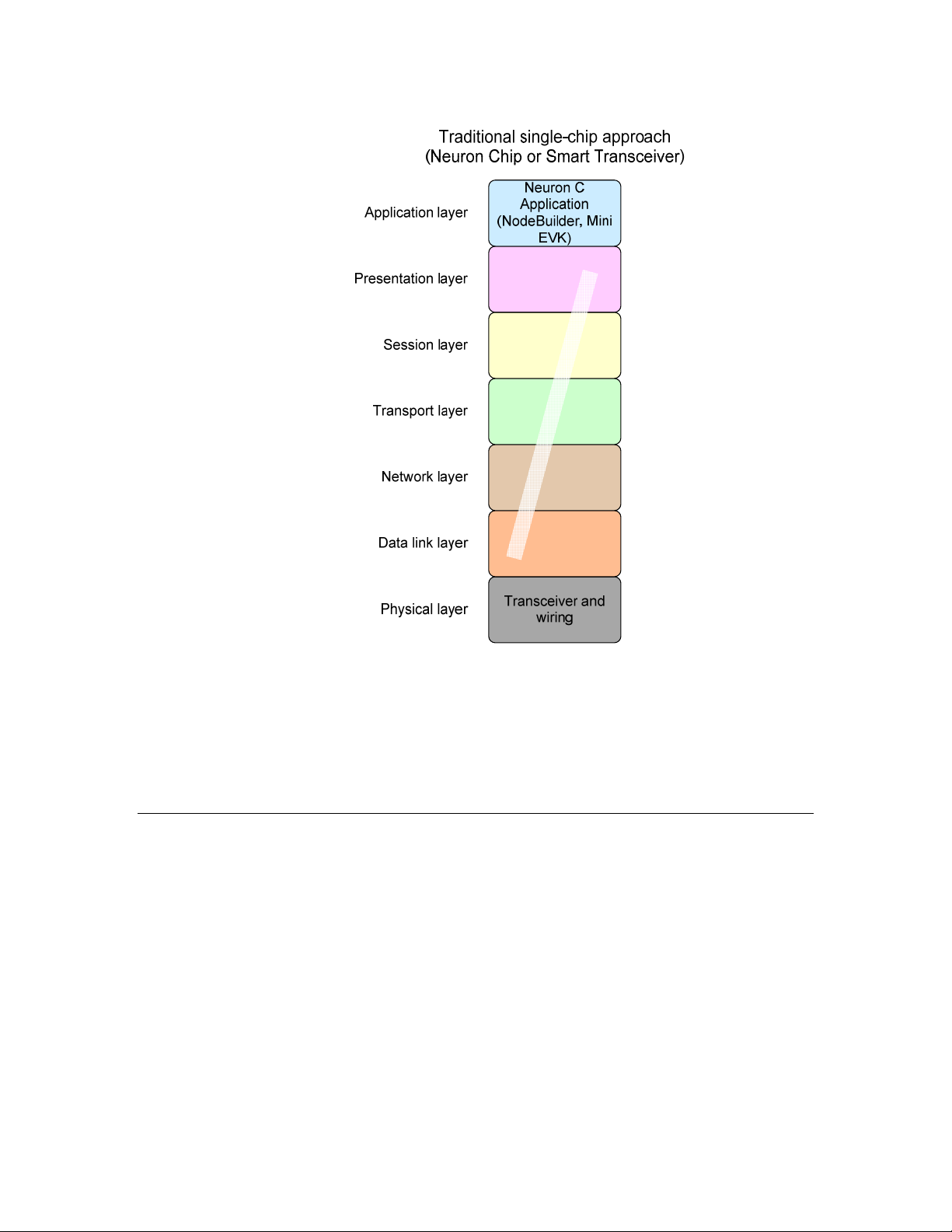
network communications through the seven abstract layers described in
The implementation of these layers in a L
interconnectivity for devices within a L
Table 2. L
ONWORKS Network Protocol Layers
ONWORKS device provides standardized
ONWORKS network.
Table 2.
OSI Layer Purpose Services Provided
7 Application Application compatibility Network configuration, self-installation,
network diagnostics, file transfer,
application configuration, application
specification, alarms, data logging,
scheduling
6 Presentation Data interpretation Network variables, application messages,
foreign frame transmission
5 Session Control Request/response, authentication
4 Transport End-to-end
communication reliability
Acknowledged and unacknowledged
message delivery, common ordering,
duplicate detection
3 Network Destination addressing Unicast and multicast addressing,
routers
2 Data Link Media access and framing Framing, data encoding, CRC error
checking, predictive carrier sense
multiple access (CSMA), collision
avoidance, priority, collision detection
1 Physical Electrical interconnect Media-specific interfaces and modulation
schemes
Echelon’s implementation of the ANSI/CEA-709.1 Control Network Protocol is
called the
LonTalk protocol
. Echelon has implementations of the LonTalk
protocol in several product offerings, including the Neuron firmware (which is
®
included in a ShortStack
i
.LON® servers, and the FTXL LonTalk protocol stack. This document refers to
Micro Server), LNS® Server, LNS remote client,
2 Introduction to FTXL
Page 15

the ANSI/CEA-709.1 (EN14908-1) Control Network Protocol as the “LonTalk
protocol”, although other interoperable implementations exist.
A LONWORKS Device with a Single Processor Chip
A basic LONWORKS device consists of four primary components:
1. An application processor that implements the application layer, or both
the application and presentation layers, of the LonTalk protocol
2. A protocol engine that implements layers 2 through 5 (or 2 through 7) of
the LonTalk protocol
3. A network transceiver that provides the physical interface for the
L
ONWORKS network communications media, and implements the physical
layer of the LonTalk protocol
4. Circuitry to implement the device I/O
These components can be combined in a physical device. For example, Echelon’s
Smart Transceiver product can be used as a single-chip solution that combines all
four components in a single chip. When used in this way, the Smart Transceiver
runs the device’s application, implements the LonTalk protocol, and interfaces
with the physical communications media through a transformer.
4 shows the seven-layer LonTalk protocol on a single Neuron Chip or Smart
page
Transceiver.
A L
ONWORKS device that uses a single processor chip is called a
device, which means that the Neuron-based processor (the Smart Transceiver)
runs both the application and the LonTalk protocol.
Figure 1 on
Neuron-hosted
FTXL User’s Guide 3
Page 16
re
wa
m
r
i
F
n
o
r
u
e
N
Figure 1. A Single-Chip L
For a Neuron-hosted device that uses a Neuron Chip or Smart Transceiver, the
physical layer (layer 1) is handled by the Neuron Chip or Smart Transceiver.
The middle layers (layers 2 through 6) are handled by the Neuron firmware. The
application layer (layer 7) is handled by your Neuron C application program. You
create the application program using the Neuron C programming language in
either the NodeBuilder
®
Development Tool or the Mini EVK Evaluation Kit.
ONWORKS Device
A LONWORKS Device with Two Processor Chips
Some LONWORKS devices run applications that require more memory or
processing capabilities than a single Neuron Chip or Smart Transceiver can
provide. Other L
an existing processor and application. For these applications, the device uses two
processor chips working together:
• An Echelon Smart Transceiver
• A microprocessor, microcontroller, or embedded processor in a field-
programmable gate array (FPGA) device, typically called the
processor
A L
ONWORKS device that uses two processor chips is called a
which means that the device includes a Smart Transceiver plus a host processor.
4 Introduction to FTXL
ONWORKS devices are implemented by adding a transceiver to
host
host-based
device,
Page 17

Compared to the single-chip device, the Smart Transceiver implements only a
subset of the LonTalk protocol layers. The host processor implements the
remaining layers and runs the device’s application program. The Smart
Transceiver and the host processor communicate with each other through a linklayer interface.
For a single-chip, Neuron-hosted, device you write the application program in
Neuron C. For a host-based device, you write the application program in ANSI C,
C++, or other high-level language, using a common application framework and
application programming interface (API). This API is called the
addition, for a host-based device, you select a suitable host processor and use the
host processor’s application development environment, rather than the
NodeBuilder Development Tool or the Mini EVK application, to develop the
application.
LonTalk API
. In
Echelon provides the following solutions for creating host-based L
devices:
• The LonTalk Platform for ShortStack Micro Servers
• The LonTalk Platform for FTXL Transceivers
ONWORKS
LonTalk Platform for ShortStack Micro
Servers
The LonTalk Platform for ShortStack Micro Servers is a set of development tools,
APIs, and firmware for developing host-based L
LonTalk Compact API and a ShortStack Micro Server.
A ShortStack Micro Server is a Smart Transceiver with firmware, the
firmware
protocol, as shown in
application layer (layer 7) and part of the presentation layer (layer 6).
The ShortStack firmware allows you to use almost any host processor for your
device’s application and I/O. The Smart Transceiver implements layers 2 to 5
(and part of layer 6) of the LonTalk protocol and provides the physical interface
for the L
A simple serial communications interface provides communications between the
ShortStack Micro Server and the host processor. Because a ShortStack Micro
Server can work with any host processor, you must provide the serial driver
implementation, although Echelon does provide the serial driver API and an
example driver for some host processors. Currently, example drivers are
available for an Atmel
processor.
For ShortStack device development, you use the C programming language
use the Echelon LonTalk Interface Developer utility to create the application
framework. Your application uses an ANSI C API, the Echelon LonTalk
Compact API, to manage communications with the ShortStack Micro Server and
devices on the L
, that implements layers 2 to 5 (and part of layer 6) of the LonTalk
Figure 2 on page 6. The host processor implements the
ONWORKS communications channel.
®
ARM7 microprocessor and an Altera Nios II embedded
ONWORKS network.
ONWORKS devices that use the
ShortStack
1
. You
1
For ShortStack device development, you could alternatively use any programming language
supported by the host processor if you port the LonTalk Compact API and the application framework
generated by the LonTalk Interface Developer utility to that language.
FTXL User’s Guide 5
Page 18

Using a ShortStack Micro Server makes it easy to add LONWORKS networks to
any existing smart device.
ShortStack Device
Application in any
suitable language
Link layer
Link layer
Transceiver and
wiring
FT 3120, PL 3120,
FT 3150, or PL 3150
Smart Transceiver
SCI or SPI serial I/O
link layer and driver
software
Host Processor
Figure 2. The ShortStack Solution for a Host-Based L
ONWORKS Device
LonTalk Platform for FTXL Transceivers
The LonTalk Platform for FTXL Transceivers is a set of development tools, APIs,
firmware, and chips for developing host-based L
LonTalk API and an FTXL Transceiver.
An FTXL Transceiver is an FT 3190 Smart Transceiver with firmware that
implements the data link layer (layer 2) of the LonTalk protocol, as shown in
Figure 3 on page 8. The host processor implements the remaining layers (layers
3 to 7). Included with the FTXL development tools is the FTXL LonTalk protocol
stack, which implements layers 3 to 6 of the LonTalk protocol and runs on the
host processor. Your application implements the application layer (layer 7).
6 Introduction to FTXL
ONWORKS devices that use the
Page 19

For an FTXL device, you use an Altera Nios II processor as the host processor for
your device’s application and I/O. The Nios II processor runs on an Altera
Cyclone II or Cyclone III FPGA device. The FTXL LonTalk protocol stack
implements layers 3 to 6 of the LonTalk protocol, and the FTXL Transceiver
implements layers 1 and 2, including the physical interface for the L
ONWORKS
communications channel.
The FTXL LonTalk protocol stack includes a communications interface driver for
the parallel link layer that manages communications between the FTXL LonTalk
protocol stack within the Nios II host processor and the FTXL Transceiver. You
need to include the physical implementation of the parallel link layer in your
FTXL device design. However, you do not need to provide the software
implementation of the parallel interface driver because it is included with the
FTXL LonTalk protocol stack, nor can you modify the Echelon-provided
implementation.
For FTXL device development, you use a C or C++ compiler that supports the
Nios II processor. As with ShortStack development, you use the Echelon
LonTalk Interface Developer utility to create the application framework. Your
application uses an ANSI C API, the Echelon LonTalk API, to manage
communications with the FTXL LonTalk protocol stack, FTXL Transceiver, and
devices on the L
ONWORKS network.
Using an FTXL Transceiver, it is easy to add L
performance FPGA-based smart device.
ONWORKS networking to a high-
FTXL User’s Guide 7
Page 20
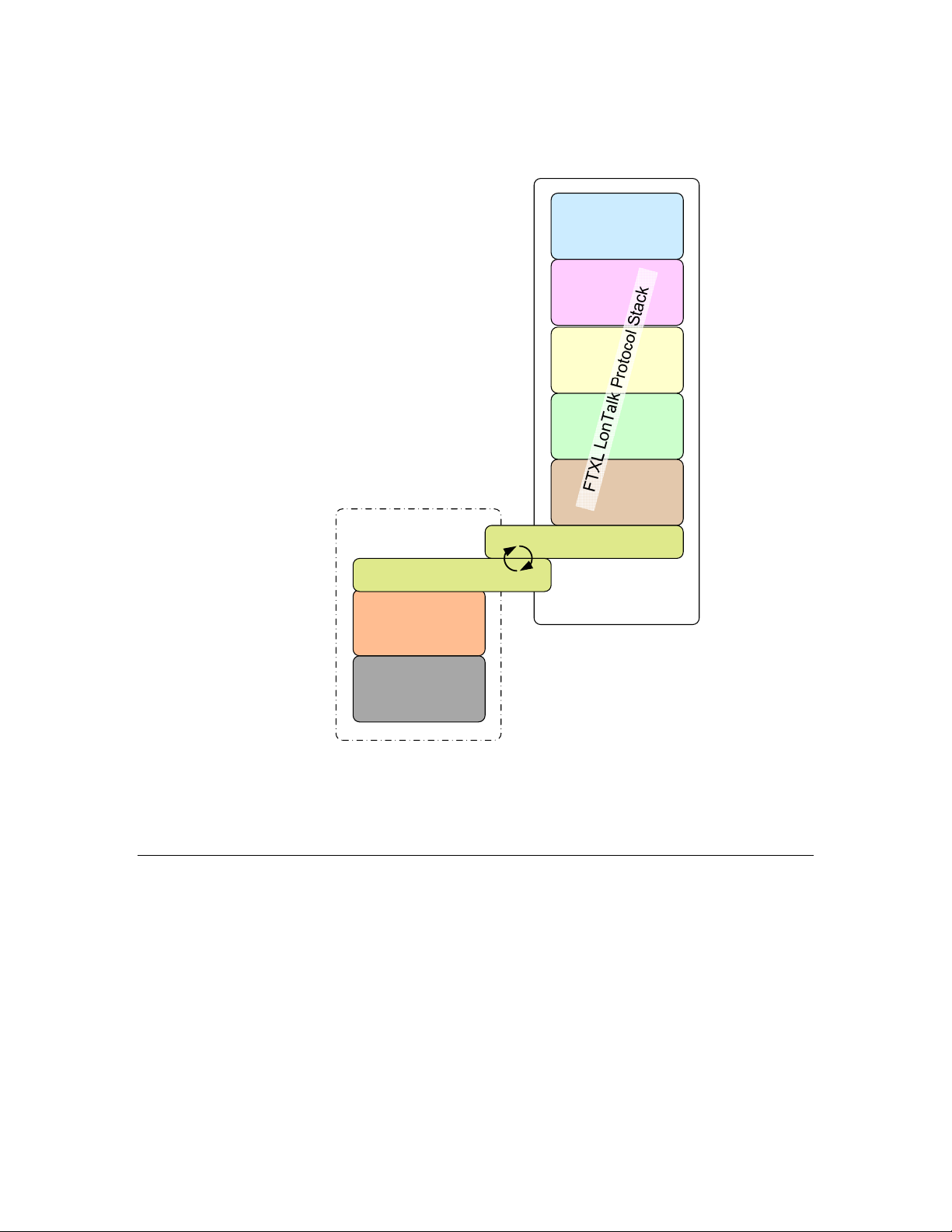
FTXL Device
Application in C
Link layer
Link layer
Transceiver and
wiring
FTXL 3190 Free
Topology Smart
Transceiver
Figure 3. An FTXL Device
11-pin parallel I/O
link layer and driver
software
Nios II
Host Processor
Comparing Neuron-Hosted, ShortStack, and FTXL Devices
Table 3 on page 9 compares some of the key characteristics of the Neuron-hosted
and host-based solutions for L
ONWORKS devices.
8 Introduction to FTXL
Page 21

Table 3. Comparing Neuron-Hosted and Host-Based Solutions for L
NeuronHosted
Characteristic
Maximum number of
Solution ShortStack Solution FTXL Solution
62 254
[1]
4096
network variables
Maximum number of
62 127
[2]
8192
aliases
Maximum number of
15 15 4096
addresses
Maximum number of
0 0 4096
dynamic network
variables
Maximum number of
16 16 200
receive transaction
records
Maximum number of
2 2 2500
transmit transaction
records
ONWORKS Devices
Support for the
No No Yes
LonTalk Extended
Command Set
File access methods
supported
FTP
DMF
[4]
,
FTP
[4]
, DMF FTP
Link-layer type N/A 4- or 5-line SCI
or
6- or 7-line SPI
Typical host API
runtime footprint
N/A 5-6 KB code with 1 KB RAM
(includes serial driver, but
does not include optional
API or ISI API)
Host processor type N/A Any 8-, 16-, 32-, or 64-bit
microprocessor or
microcontroller
Application
Neuron C Any (typically ANSI C) ANSI C or C++ for the
development
language
[3]
[4]
, DMF
11-line parallel I/O
[5]
[6]
540 KB (includes
LonTalk protocol stack,
but does not include the
application or operating
system)
Altera Nios II embedded
processor
Nios II processor
FTXL User’s Guide 9
Page 22

Notes:
1. ShortStack Micro Servers running on FT 3150 or PL 3150 Smart Transceivers
support up to 254 network variables. ShortStack Micro Servers running on FT
3120 Smart Transceivers support up to 240 network variables, and ShortStack
Micro Servers running on PL 3120 Smart Transceivers support up to 62 network
variables. A custom Micro Server can support up to 254 network variables,
depending on available resources.
2. ShortStack Micro Servers running on FT 3150 or PL 3150 Smart Transceivers
support up to 127 aliases. ShortStack Micro Servers running on FT 3120 Smart
Transceivers support up to 120 aliases. ShortStack Micro Servers running on PL
3120 Smart Transceivers support up to 62 aliases. A custom Micro Server can
support up to 127 aliases, depending on available resources.
3. See the
more information about the extended command set (ECS) network management
commands. This document is available from the IHS Standards Store:
global.ihs.com/doc_detail.cfm?item_s_key=00391891&item_key_date=971131&rid=
CEA.
4. An implementation of the L
with the product.
5. For more information about the direct memory files (DMF) feature, see
Memory Files
6. The FTXL parallel I/O link-layer driver is included with the FTXL LonTalk protocol
stack.
LonTalk Control Network Protocol Specification
ONWORKS file transfer protocol (FTP) is not provided
on page 96.
The FTXL solution provides the best performance and highest network capacity,
but is limited using to an Altera Nios II host processor and the TP/FT-10 channel.
The ShortStack solution provides support for any host processor (with available
examples for both an Atmel ARM7 host processor and an Altera Nios II host
processor), and supports both the TP/FT-10 and PL-20 channels. The ShortStack
solution supports fewer network variables and aliases that the FTXL solution,
but more network variables and aliases than the Neuron-hosted solution.
Because the ShortStack and FTXL solutions are both built on the LonTalk
platform, they share a very similar API (the FTXL LonTalk API and the
ShortStack LonTalk Compact API). Thus, migrating applications from one
solution to the other is fairly easy. In addition, you can create applications that
share a common code base for devices that use both solutions.
, EIA/CEA 709.1-B-2002, for
Using Direct
Requirements and Restrictions for FTXL
The FTXL Developer’s Kit supports only the FTXL 3190 Free Topology Smart
Transceiver. It does not support other transceiver types.
The FTXL LonTalk protocol stack requires that the FTXL application use an
embedded operating system. The FTXL Developer’s Kit includes an example
application that uses the Micrium μC/OS-II operating system, but you can use
any embedded operating system that meets your application’s requirements.
And although the μC/OS-II operating system is a real-time operating system, the
FTXL LonTalk protocol stack does not require the operating system to be a realtime operating system.
10 Introduction to FTXL
Page 23

The FTXL LonTalk protocol stack and API require about 540 KB of program
memory on the Nios II host processor, not including the application program or
the operating system. In addition, you must provide sufficient additional nonvolatile memory for device configuration data and any non-volatile data that you
include in your application.
You can implement configuration properties as configuration network variables
or in configuration files. To access configuration files, you can implement the
ONWORKS file transfer protocol (FTP) or use the direct memory files (DMF)
L
feature. See
when to use FTP or the DMF feature.
Using Direct Memory Files
on page 96 for more information about
Development Tools for FTXL
To develop an application for a device that uses an FTXL Transceiver, you need a
development system for the Nios II processor. In addition, you need the FTXL
Developer’s Kit, which includes:
• The FTXL LonTalk API
• The LonTalk
your FTXL device and generating the application framework
• Example FTXL applications
• A reference design for a Nios II processor and associated hardware for
the FPGA device
You also need a network management tool to install and test your FTXL device.
You can use the LonMaker Integration Tool, or any other tool that can install and
monitor L
information on the LonMaker tool.
You do not need the NodeBuilder Development Tool to use the FTXL Developer's
Kit; however, the NodeBuilder Code Wizard that is included with the
NodeBuilder tool, version 3 or later, can help you develop your Neuron C model
file. The model file is used to define the device’s interoperable interface.
ONWORKS devices. See the
Interface Developer utility for defining the interface for
FTXL Architecture
An FTXL device consists of the following components:
• The FTXL 3190 Free Topology Smart Transceiver running the FTXL
firmware
• A Nios II embedded processor running the following software:
• An FTXL host application that uses the FTXL LonTalk API
LonMaker User's Guide
for more
• The FTXL LonTalk protocol stack
• The FTXL hardware abstraction layer (HAL)
• The FTXL non-volatile data (NVD) driver
• The FTXL operating system abstraction layer (OSAL)
• An embedded operating system
• The Altera SOPC Builder hardware abstraction layer (HAL)
FTXL User’s Guide 11
Page 24
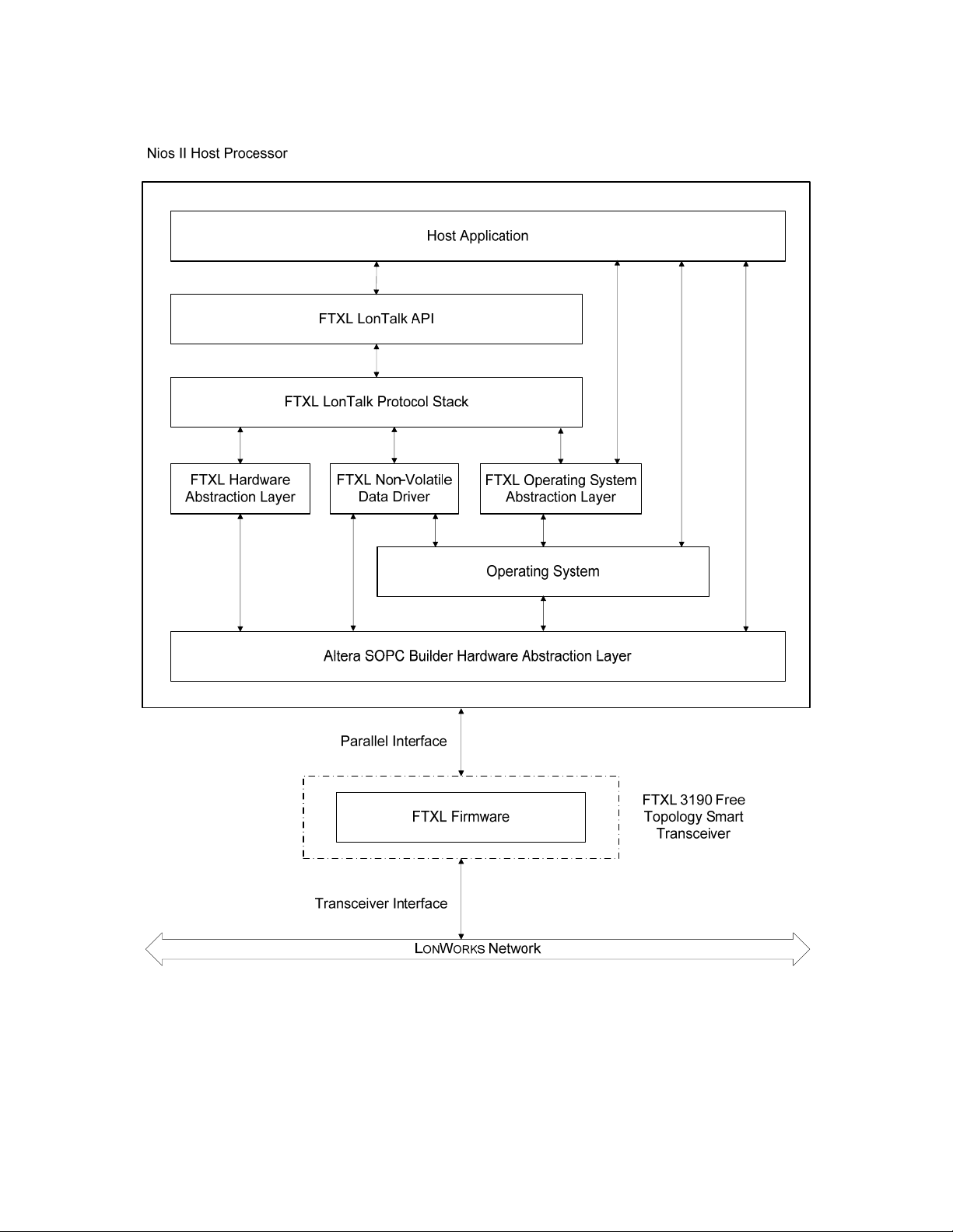
Figure 4 shows the basic architecture of an FTXL device.
Figure 4. FTXL Architecture
The FTXL Developer's Kit includes the FTXL LonTalk API and a precompiled
library that implements the FTXL LonTalk protocol stack. The kit also includes
source code for additional operating system and hardware APIs that you compile
and link with your application. The FTXL LonTalk API defines the functions
that your application calls to communicate with other devices on a L
network. The API code provides ANSI C interfaces for the host application.
12 Introduction to FTXL
ONWORKS
Page 25

The FTXL LonTalk API consists of the following types of functions:
• Functions to initialize the FTXL device after each reset.
• A function that the application must call periodically. This function
processes messages pending in any of the data queues.
• Various functions to initiate typical operations, such as the propagation
of network variable updates.
• Event handler functions to notify the application of events, such as the
arrival of network variable data or an error in the propagation of an
application message.
• Functions to interface with the operating system.
The FTXL Developer’s Kit
The FTXL Developer’s Kit consists of two components: a hardware component
and a software component. See the
the hardware component of the FTXL Developer’s Kit.
The software component contains the software required to develop FTXL
applications that use an FTXL Transceiver:
1. The FTXL LonTalk protocol stack library and FTXL LonTalk API
2. ANSI C source code for event handler functions.
FTXL Hardware Guide
for information about
3. Portable ANSI C source code for the reference implementations of the
APIs for the operating system and hardware.
4. The LonTalk Interface Developer utility that you use to generate device
interface data, device interface files, and a skeletal application
framework.
5. Example applications that run on the reference design hardware.
The software component of the FTXL Developer’s Kit is available as a free
download from the Echelon Web site:
must acquire a licence from Echelon to use the FTXL Developer’s Kit.
www.echelon.com/downloads. You also
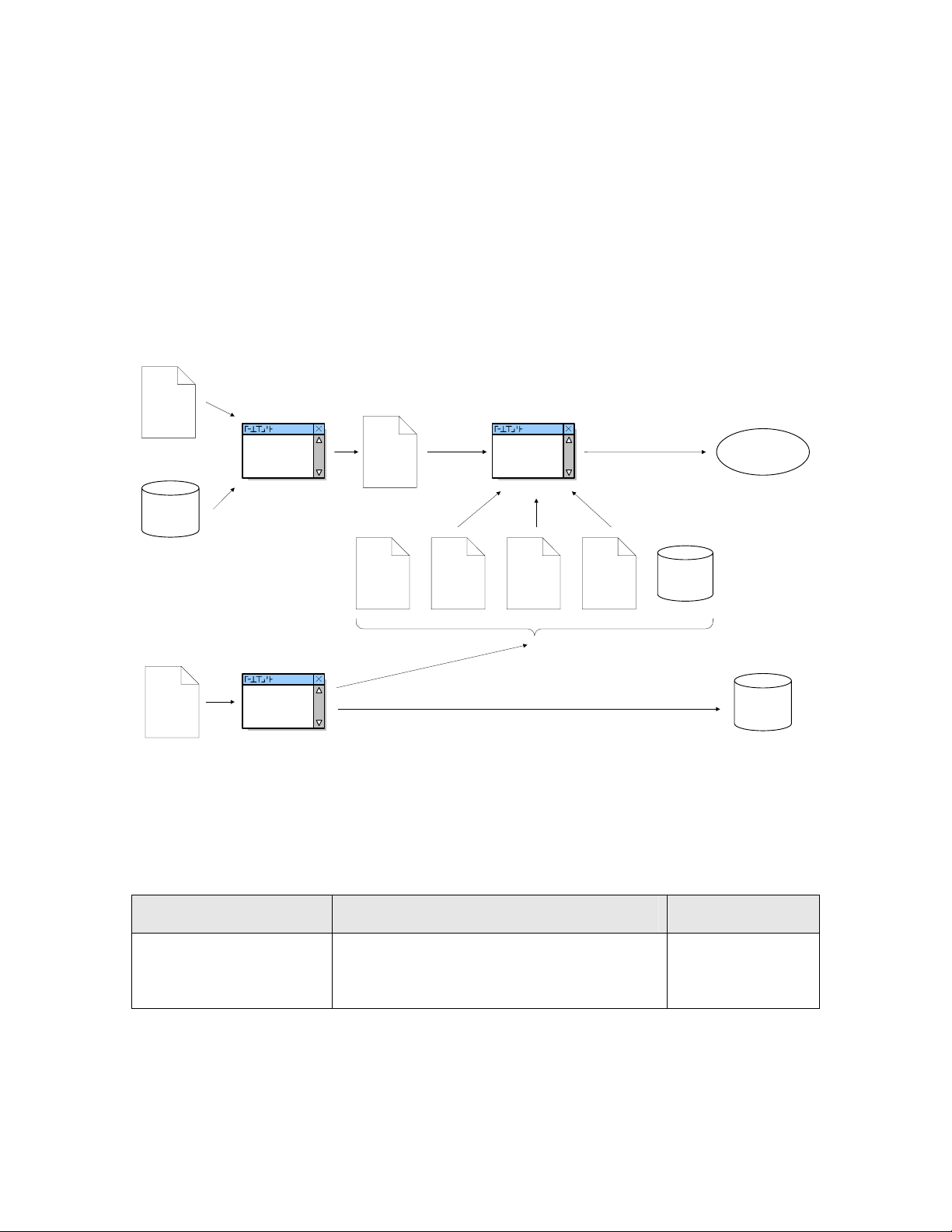
Overview of the FTXL Development Process
Figure 5 on page 14 shows a high-level overview of the development process for
an FTXL application. The basic process includes the following steps:
1. Use the Altera Quartus II software and SOPC Builder tool, with input
from FTXL hardware components and your FPGA design, to generate
compiled hardware description files.
2. Use the LonTalk Interface Developer utility, with input from a model file
that you create, to generate application framework files and interface
files.
3. Use the Altera Nios II EDS IDE to create the FTXL application, with
input from:
• The application framework files generated by the LonTalk Interface
Developer utility
FTXL User’s Guide 13
Page 26
Source
FPGA
Hardware
Description
Files
FTXL Hardware
Components
• The FTXL hardware abstraction layer (HAL) files, which you might
need to modify
• The FTXL operating system abstraction layer (OSAL) files, which you
might need to modify
• The FTXL non-volatile data (NVD) driver files, which you might need
modify
• The FTXL LonTalk protocol stack
Because an FTXL device is comprised of both hardware and software
components, different people can be involved in the various steps, and these steps
can occur in parallel or sequentially. The figure does not imply a required order
of steps.
Quartus II
Software and
SOPC Builder
Compiled
FPGA
Hardware
Description
Files
Nios II EDS
IDE
FTXL Application
Source
Model File
(*.nc)
LonTalk
Interface
Developer
Generated
Application
Framework
Files
FTXL HAL FTXL OSAL
FTXL NVD
Driver
FTXL LonTalk
Protocol Stack
Interface Files
(*.xif and *.xfb)
Figure 5. Overview of the FTXL Development Process
For more information about hardware development for an FTXL device, see the
FTXL Hardware Guide
.
This manual describes the software development process for creating an FTXL
device, which includes the general tasks listed in
Table 4.
Table 4. Tasks for Developing Software for an FTXL Device
Task Additional Considerations Reference
Install the FTXL
Developer’s Kit and
become familiar with it
Chapter
Started with
FTXL
2,
, on page 17
Getting
14 Introduction to FTXL
Page 27

Task Additional Considerations Reference
Select an FPGA device
and load it with Nios II
processor and related
hardware
Integrate the FTXL
application with your
device hardware
Test and verify your
hardware design
Select and define the
functional profiles and
resource types for your
device using tools such as
the NodeBuilder
Resource Editor and the
SNVT and SCPT Master
List
The FTXL application runs on a Nios II
embedded processor, which is implemented
on an FPGA device. You must meet the
FTXL hardware and software requirements
to ensure that the FTXL device has
sufficient RAM and non-volatile memory.
You integrate the FTXL Transceiver with
the device hardware. You can reuse many
parts of a hardware design for different
applications to create different FTXL
devices.
You must ensure that the host processor
and the FTXL Transceiver can
communicate using the parallel interface.
The FTXL Developer’s Kit includes a BringUp application to help test and verify the
communications interface.
You must select profiles and types for use in
the device’s interoperable interface for each
application that you plan to implement.
This selection can include the definition of
user-defined types for network variables,
configuration properties or functional
profiles. A large set of standard definitions
is also available and is sufficient for many
applications.
FTXL
The
Hardware Guide
FTXL
The
Hardware Guide
Chapter 6,
Working with the
Nios II
Development
Environment
101
page
FTXL
The
Hardware Guide
Chapter
, on
3,
Creating a Model
, on page 23
File
Structure the layout and
interoperable interface of
your FTXL device by
creating a model file
FTXL User’s Guide 15
You must define the interoperable interface
for your device in a model file, using the
Neuron C (Version 2.1) language, for every
application that you implement. You can
write this code by hand, derive it from an
existing Neuron C or ShortStack
application, or use the NodeBuilder Code
Wizard included with the NodeBuilder
Development Tool to create the required
code using a graphical user interface.
Chapter
Creating a Model
File
Appendix
Neuron C Syntax
for the Model File
on page
3,
, on page 23
125
C,
,
Page 28

Task Additional Considerations Reference
Use the LonTalk
Interface Developer
utility to generate device
interface data, device
interface files, and a
skeleton application
framework
Complete the FTXL
LonTalk API event
handler functions and
callback handler
functions to process
application-specific
ONWORKS events
L
Modify the FTXL
Operating System
Abstraction Layer
(OSAL) files for your
application’s operating
system
You must execute this utility, a simple
click-through wizard, whenever the model
file changes or other preferences change.
The utility generates the interface files
(including the XIF file) and source code that
you can compile and link with your
application. This source code includes data
that is required for initialization and for
complete implementations of some aspects
of your device.
You must complete the event handler
functions and callback handler functions for
every application that you implement,
because they provide input from network
events to your application, and because
they are part of your networked device’s
control algorithm.
If you use the Micrium μC/OS-II operating
system, you can use the OSAL files that are
included with the FTXL Developer’s Kit.
4,
Chapter
Using
the LonTalk
Interface
Developer Utility
on page
Chapter
55
5,
,
Developing an
FTXL Application
147
73
D,
FTXL
, on
on page
Appendix
LonTalk API
page
The FTXL
Operating System
Abstraction Layer
on page
157
,
Modify the non-volatile
data (NVD) driver files
Modify your application
to interface with a
ONWORKS network by
L
using the FTXL LonTalk
API function calls
Test, install, and
integrate your FTXL
device using a
ONWORKS network tool
L
such as the LonMaker
Integration Tool
Depending on the type of non-volatile
memory that your device uses, you can use
one of the non-volatile data drivers
provided with the FTXL Developer’s Kit,
make minor modifications to one of these
drivers, or implement your own driver.
You must make these function calls for
every application that you implement.
These calls include, for example, calls to the
LonPropagateNv() function that propagates
an updated network variable value to the
network. Together with the completion of
the event and callback handler functions,
this task forms the core of your networked
device’s control algorithm.
The
Providing
Persistent Storage
for Non-Volatile
on page 77
Data
Chapter
5,
Developing an
FTXL Application
147
73
D,
FTXL
, on
on page
Appendix
LonTalk API
page
LonMaker
User's Guide
,
16 Introduction to FTXL
Page 29

2
Getting Started with FTXL
This chapter describes the FTXL Developer’s Kit and how to install it.
FTXL User’s Guide 17
Page 30

FTXL Developer’s Kit Overview
The FTXL Developer’s Kit is a development toolkit that contains the hardware
designs, software designs, and documentation needed for developing applications
that use an FTXL Transceiver. The kit includes the following components:
• Hardware and software design files for the FPGA design, including
Quartus II files, SOPC Builder files, and Nios IDE files
• Hardware component files for the FPGA development board
• The FTXL LonTalk protocol stack and FTXL LonTalk API, delivered as a
C object library
• Software source files for the FTXL LonTalk API
• A set of example programs that demonstrate how to use the FTXL
LonTalk API to communicate with a L
• The LonTalk Interface Developer utility, which defines parameters for
your FTXL host application program and generates required device
interface data for your device
ONWORKS network
• Documentation, including this
, and HTML documentation for the FTXL API
Guide
The FTXL Developer’s Kit also refers to three hardware development boards that
are available from devboards GmbH,
can also obtain these boards from EBV Elektronik GmbH,
FTXL Developer’s Kit uses these boards for its examples and reference designs.
These boards are:
• The
• The
• The
Contact your Altera representative for information about acquiring a Nios II
development license.
See the
development boards and the reference designs for the FTXL Developer’s Kit.
The software for the FTXL Developer’s Kit is available as a free download from
www.echelon.com/ftxl.
DBC2C20 Altera Cyclone II Development Board
FPGA device and peripheral I/O
FTXL Adapter Board
between the DBC2C20 development board and the FTXL Transceiver
Board
FTXL Transceiver Board
Transceiver Chip and a L
FTXL Hardware Guide
for more information about the hardware
FTXL User’s Guide
www.devboards.de. European customers
, which primarily provides voltage regulation
, which includes the FTXL 3190 Smart
ONWORKS network connector
, the
FTXL Hardware
www.ebv.com. The
, which provides the
Installing the FTXL Developer’s Kit
The FTXL Developer’s Kit requires the following software:
• Altera Quartus II software, Version 7.2 or later
• Altera Nios II EDS integrated development environment (IDE), Version
7.2 or later
18 Getting Started with FTXL
Page 31

• Driver software for the Altera USB-Blaster download cable
• FPGA configuration data and software for the DBC2C20 development
board (included with the FTXL Developer’ Kit)
For more information about the Altera software products, see see Chapter
Working with the Nios II Development Environment
Web site for the Nios II processor,
www.altera.com/products/ip/processors/nios2/ni2-index.html.
The following sections describe the hardware and software requirements, and
how to install the FTXL Developer’s Kit.
Hardware Requirements
For the FTXL Developer’s Kit plus the Altera design software, your computer
system must meet the following minimum requirements:
®
• Intel
• 256 MB RAM
• 5 GB available hard disk space (includes the space required for the Altera
• CD-ROM drive
• 1 available Universal Serial Bus (USB) port
The recommended specifications for your computer system include:
• Intel Pentium 4 2.0 GHz processor
• 1 GB RAM
Pentium® III 866 MHz processor
tools)
6,
, on page 101, and the Altera
• 5 GB available hard disk space
• CD-ROM or DVD-ROM drive
• 2 available USB ports
In addition, you must have the following hardware for L
• L
ONWORKS compatible network interface, such as a U10 USB Network
i
Interface or an
• A L
ONWORKS TP/FT-10 network cable, with network terminator
.LON 100 Internet Server
Software Requirements
For the FTXL Developer’s Kit plus the Altera design software, your computer
system must meet one of the following minimum requirements:
®
• Microsoft
• Microsoft Windows Vista
The following software is optional, depending on your requirements:
• Adobe Reader 7.0.8 or later
Windows® XP, plus Service Pack 2 or later
ONWORKS connectivity:
FTXL User’s Guide 19
Page 32

DBC2C20 Software
Although the DBC2C20 Altera Cyclone II Development Board includes a set of
software for general FPGA development, you do not need to install any of the
DBC2C20 software to work with the FTXL Developer’s Kit. All of the necessary
FPGA components and other software for the DBC2C20 development board are
installed with the FTXL Developer’s Kit.
Installing the FTXL Developer’s Kit
To install the FTXL Developer’s Kit, perform the following steps:
1. Download the FTXL Developer’s Kit from
Although the download is free, you must agree to the licence terms for the
FTXL Developer’s Kit when you download it.
2. Double click the FtxlDevKit100.exe file that you downloaded. The
Echelon FTXL Developer’s Kit main installer window opens.
3. Follow the installation dialogs to install the FTXL Developer’s Kit onto
your computer.
After you install the kit, you can integrate it into your Nios II application
development environment, as described in Chapter
Development Environment
In addition to the FTXL Developer’s Kit, the installation program also installs:
• L
ONMARK
• L
ONMARK Standard Program ID Calculator
• NodeBuilder Resource Editor
FTXL API Files
The FTXL LonTalk protocol stack and FTXL LonTalk API are provided as a C
object library. In addition, the FTXL Developer’s Kit includes a set of portable
ANSI C files that accompany the API, which are listed in
contained in the [
you installed FTXL, usually C:\LonWorks\FTXL). In addition, there is a backup
of these files in a ZIP file in the [
, on page 101.
®
Resource Files
FTXL
]\Core directory (where [
FTXL
www.echelon.com/ftxl.
6,
Working with the Nios II
Table 5. These files are
FTXL
] is the directory in which
]\SourceArchive directory.
The LonTalk Interface Developer utility automatically copies these files into the
project folder, but does not overwrite existing files with the same names.
Table 5. FTXL LonTalk API Files
File Name Description
FtxlApi.h Function definitions for the FTXL LonTalk API
FtxlHal.h
FtxlHal.c
20 Getting Started with FTXL
Functions for the FTXL hardware abstraction layer (HAL)
Page 33

File Name Description
FtxlHandlers.c
FtxlNvdFlashDirect.c
FtxlNvdFlashFs.c
FtxlNvdUserDefined.c
FtxlOsal.h
FtxlOsal.c
FtxlTypes.h C type definitions that are used by the FTXL LonTalk API
libFtxl100.a C library for the FTXL LonTalk protocol stack and FTXL LonTalk
LonPlatform.h Definitions for adjusting your compiler and development
Function definitions for the FTXL event handler functions and
callback handler functions
Functions for managing non-volatile data
Functions for the FTXL operating system abstraction layer (OSAL)
API
environment to the requirements of the FTXL LonTalk API
LonTalk Interface Developer
The LonTalk Interface Developer utility generates the device interface data and
device interface files required to implement the device interface for your FTXL
device. It also creates a skeleton application framework that you can modify and
link with your application. This framework contains most of the code that is
needed for initialization and other required processing.
The executable for the LonTalk Interface Developer utility is named LID.exe, and
is installed in the LonTalk Interface Developer directory (usually,
C:\LonWorks\InterfaceDeveloper).
The LonTalk Interface Developer utility also includes a command-line interface
that allows make-file and script-driven use of the utility. For more information
about the command-line interface, see Appendix
Command Line Usage
For more information about the LonTalk Interface Developer utility, see Chapter
4,
Using the LonTalk Interface Developer Utility
, on page 111.
Example FTXL Applications
The FTXL Developer’s Kit includes two example applications that run on the
reference designs for the development boards that are available from
devboards.de GmbH. The first example is a simple FTXL application that
simulates a voltage amplifier, whereas the second example demonstrates the use
of dynamic network variables and changeable-type network variables.
G,
See Appendix
about these examples.
Example FTXL Applications
A,
LonTalk Interface Developer
, on page 55.
, on page 195, for more information
FTXL User’s Guide 21
Page 34

22 Getting Started with FTXL
Page 35

3
Creating a Model File
You use a model file to define your device’s interoperable
interface, including its network inputs and outputs. The
LonTalk Interface Developer utility converts the information
in the model file into device interface data and a device
interface file for your application. This chapter describes
how to create a model file using the Neuron C programming
language.
Syntax for the Neuron C statements in the model file is
C,
described in Appendix
, on page 125.
File
Neuron C Syntax for the Model
FTXL User’s Guide 23
Page 36

Model File Overview
The interoperable application interface of a LONWORKS device consists of its
functional blocks, network variables, configuration properties, and their
relationships. The
receiving data using interoperable data types. The
the device’s means of providing externally exposed configuration data, again
using interoperable data types. The configuration data items can be read (and
typically also written) by a network tool. The device interface is organized into
functional blocks
and configuration properties that are used to perform one task. These network
variables and configuration properties are called the
The model file describes the functional blocks, network variables, configuration
properties, and their relationships, that make up the interoperable interface for
an FTXL device, using the Neuron C programming language. Neuron C is based
on ANSI C, and is designed for creating a device’s interoperable interface and
implementing its algorithms to run on Neuron Chips and Smart Transceivers.
However, you do not need to be proficient in Neuron C to create a model file for
an FTXL application because the model file does not include executable code. All
tools required to process model files are included with FTXL; you do not need to
license another Neuron C development tool to work with an FTXL model file.
The model file uses Neuron C Version 2.1 declaration syntax.
The LonTalk Interface Developer utility uses the model file to generate device
interface data and device interface files. You can use any of the following
methods to create a model file:
network variables
, each of which groups together a collection of network variables
are the device’s means of sending and
configuration properties
functional block members
are
.
• Manually create a model file
A model file is a text file that you can create with any text or
programming editor, including Windows Notepad. Model files have the
.nc file extension. This chapter describes the types of Neuron C
statements you can include in a model file. Appendix
syntax for the Neuron C statements.
• Reuse existing Neuron C code
You can reuse an existing Neuron C application that was originally
written for a Neuron Chip or a Smart Transceiver as a model file. The
LonTalk Interface Developer utility uses only the device interface
declarations from a Neuron C application program, and ignores all other
code. You might have to delete some code from an existing Neuron C
application program, or exclude this code using conditional compilation,
as described later in this chapter.
• Automatically generate a model file
You can use the NodeBuilder Code Wizard, included with Release 3 or
later of the NodeBuilder Development Tool, to automatically generate a
model file. Using the NodeBuilder Code Wizard, you can define your
device interface by dragging functional profiles and type definitions from
a graphical view of your resource catalog to a graphical view of your
device interface, and refine them using a convenient graphical user
interface. When you complete the device interface definition, click the
Generate Code and Exit button to automatically generate your model file.
Use the main file produced by the NodeBuilder Code Wizard as your
model file. NodeBuilder software is not included with the FTXL
C describes the
24 Creating a Model File
Page 37

Developer’s Kit, and must be licensed separately. See the
User’s Guide
for details about using the NodeBuilder Code Wizard.
NodeBuilder
See Appendix
detailed Neuron C syntax for each type of statement that can be included in the
model file.
C,
Neuron C Syntax for the Model File
Defining the Device Interface
You use a model file to define the device interface for your device. The device
interface for a L
• Functional blocks
• Network variables
• Configuration properties
A
functional block
properties, which are used together to perform one task. These network
variables and configuration properties are called the
Functional blocks are defined by
to describe common units of functional behavior. Each functional profile defines
mandatory and optional network variables and configuration properties. Each
functional block implements an instance of a functional profile. A functional
block must implement all of the mandatory network variables and configuration
properties defined by the functional profile, and can also implement any of the
optional network variables and configuration properties defined by the functional
profile. In addition, a functional block can implement network variables and
configuration properties that are not defined by the functional profile – these are
implementation-specific
called
ONWORKS device consists of its:
is a collection of network variables and configuration
functional profiles
network variables and configuration properties.
, on page 125, for the
functional block members
. A functional profile is used
.
The primary inputs and outputs to a functional block are provided by network
variables. A
get from other devices on a network (an
make available to other devices on a network (an
Network variables are used for operational data such as temperatures, pressures,
switch states, or actuator positions.
configuration property
A
device (its network variables and functional blocks). Configuration properties are
used for configuration data such as set points, alarm thresholds, or calibration
factors. Configuration properties can be set by a network management tool (such
as the LonMaker Integration tool or a customized plug-in created for the device),
and allow a network integrator to customize a device’s behavior.
These interface components, and the resource files used to define them, are
described in the following sections.
network variable
is a data item that specifies the configurations for a
is a data item that a device application expects to
input network variable
) or expects to
output network variable
Defining the Interface for an FTXL Application
Within the model file, you define a simple input network variable with the
following syntax:
network input
type name
;
).
FTXL User’s Guide 25
Page 38

Example: The following declaration defines an input network variable of type
“SNVT_type” with the name “nviAmpere”.
network input SNVT_amp nviAmpere;
You define a simple output network variable using the same syntax, but with the
output modifier:
network output
Example: The following declaration defines an output network variable of type
“SNVT_type” with the name “nvoAmpere”.
network output SNVT_amp nvoAmpere;
By convention, input network variable names have an
network variables have an
See
Network Variable Syntax
declaration syntax.
The LonTalk Interface Developer utility reads the network variable declarations
in the model file to generate device-specific code. For the example of the
nviAmpere
a standard ANSI C type definition for the
implements two global C-language variables:
typedef ncsLong SNVT_amp;
…
volatile SNVT_amp nviAmpere;
SNVT_amp nvoAmpere;
The ncsLong data type defines the host equivalent of a Neuron C signed long
variable. This type is defined in the LonPlatform.h file.
Your FTXL application can simply read the
retrieve the most recently received value from that input network variable.
Likewise, your application can write the result of a calculation to the
global C variable, and call the appropriate FTXL LonTalk API function to
propagate the network variable to the L
type name
and
nvoAmpere
;
nvi
prefix and output
nvo
prefix.
on page 132 for the full network variable
pair of network variables above, the utility generates
SNVT_amp
nviAmpere
network variable type and
global C variable to
nvoAmpere
ONWORKS network.
Choosing the Data Type
Many functional profiles define the exact type of each member network variable.
SNVT_amp
The
different network variable type within a functional profile that requires this
network variable type renders the implementation of the profile not valid.
Other profiles are generic profiles that allow various network variable types to
implement a member. The
Defining a Functional Block
the
functional profile. This profile defines the
SNVT_xxx
Implementing a generic profile allows you to choose the standard network
variable type from a range of allowed types when you create the model file.
For added flexibility, if the specific functional profile allows it, your application
can implement changeable-type network variables. A
variable
26 Creating a Model File
is network variable that is initially declared with a distinct default type
type used in the previous section is such a type. Using a
SFPTopenLoopSensor
on page 27) is an example for such a generic
nvoValue
, which means “any standard network variable type.”
functional block (described in
member to be of type
changeable-type network
Page 39

(for example,
different type (for example,
Using changeable-type network variables allows you to design a generic device
(such as a generic proportional-integral-derivative (PID) controller) that supports
a wide range of numeric network variable types for set-point, control, and
process-value network variables.
SNVT_volt
), but can be changed during device installation to a
SNVT_volt_mil
).
Defining a Changeable-Type Network Variable
See
information about implementing changeable-type network variables for FTXL
applications.
You can also define your own nonstandard data types. The NodeBuilder
Resource Editor utility, which is included with the FTXL Development Kit,
allows you to define your own, nonstandard data types for network variables or
configuration properties, and allows definition of your own, nonstandard
functional profiles. These nonstandard types are called user-defined types and
user-defined profiles.
Defining a Functional Block
The first step for defining a device interface is to select the functional profile, or
profiles, that you want your device to implement. You can use the NodeBuilder
Resource Editor to look through the standard functional profiles, as described in
Defining a Resource File
each of the standard functional profiles at
For example, if your device is a simple sensor or actuator, you can use one of the
following standard profiles:
• Open-loop sensor (SFPTopenLoopSensor)
• Closed-loop sensor (SFPTclosedLoopSensor)
• Open-loop actuator (SFPTopenLoopActuator)
on page 40. You can find detailed documentation for
on page 30 for more
types.lonmark.org2.
• Closed-loop actuator (SFPTclosedLoopActuator).
If your device is more complex, look through the other functional profiles to see if
any suitable standard profiles have been defined. If you cannot find an existing
profile that meets your needs, you can define a user functional profile, as
described in
Example: The following example shows a simple functional block declaration.
network output SNVT_amp nvoAmpere;
fblock SFPTopenLoopSensor {
nvoAmpere implements nvoValue;
} fbAmpMeter;
This functional block:
• Is named
• Implements the standard profile SFPTopenLoopSensor
Defining a Resource File
fbAmpMeter
you include the external_name keyword to define a more human-readable
name)
(network management tools use this name unless
on page 40.
2
Use the Windows Internet Explorer browser to view this site.
FTXL User’s Guide 27
Page 40

• Includes a single network variable, named
implements the nvoValue network variable member of the standard
profile
nvoAmpere
, which
Declaring a Functional Block
A functional block declaration, by itself, does not cause the LonTalk Interface
Developer utility to generate any executable code, although it does create data
that implements various aspects of the functional block. Principally, the
functional block creates associations among network variables and configuration
properties. The LonTalk Interface Developer utility uses these associations to
create the self-documentation (SD) and self-identification (SI) data in the device
and in its associated device interface file (.xif or .xfb extension).
The functional block information in the device interface file, or the SD and SI
data, communicates the presence and names of the functional blocks contained in
the device to a network management tool.
Network-variable or configuration members of a functional block also have selfdocumentation data, which is also automatically generated by the LonTalk
Interface Developer utility. This self-documentation data provides details about
the particular network variable or configuration property, including whether the
network variable or configuration property is a member of a functional block.
Functional blocks can be implemented as single blocks or as arrays of functional
blocks. In a functional block array, each member of the array implements the
same functional profile, but has different network variables and typically has
different configuration properties that implement its network variable and
configuration property members.
Example: The following example shows a simple array of 10 functional blocks.
network output SNVT_amp nvoAmpere[10];
fblock SFPTopenLoopSensor {
nvoAmpere[0] implements nvoValue;
} fbAmpMeter[10];
This functional block array:
• Contains ten functional blocks,
implementing the SFPTopenLoopSensor profile.
• Distributes the ten nvoAmpere network variables among the ten
functional blocks, starting with the first network variable (at network
variable array index zero). Each member of the network variable array
applies to a different network variable member of the functional block
array.
Defining a Network Variable
Every network variable has a type, called a
the units, scaling, and structure of the data contained within the network
variable. To connect a network variable to another network variable, both must
have the same type. This type matching prevents common installation errors
from occurring, such as connecting a pressure output to a temperature input.
fbAmpMeter[0]
to
network variable type
fbAmpMeter[9]
, that defines
, each
28 Creating a Model File
Page 41

Type translators are also available to convert network variables of one type to
another type. Some type translators can perform sophisticated transformations
between dissimilar network variable types. Type translators are special
functional blocks that require additional resources, for example, a dedicated typetranslating device in your network.
You can minimize the need for type translators by using standard network
variable types (SNVTs) for commonly used types, and by using changeable-type
network variables, where appropriate. You can also define your own user
network variable types (UNVTs).
You can use the NodeBuilder Resource Editor to look through the standard
network variable types, as described in
you can browse the standard profiles online at
You can connect network variables on different devices that are of identical type,
but opposite direction, to allow the devices to share information. For example, an
application on a lighting device could have an input network variable of the
switch type, while an application on a dimmer-switch device could have an
output network variable of the same type. You can use a network tool, such as
the LonMaker Integration Tool, to connect these two devices, allowing the switch
to control the lighting device, as shown in
Defining a Resource File
types.lonmark.org.
Figure 6.
on page 40, or
Figure 6. Simple Switch Controlling a Single Light
A single network variable can be connected to multiple network variables of the
same type but opposite direction. The example in
switch being used to control three lights.
Figure 7 shows the same
Figure 7. Simple Switch Controlling Three Lights
FTXL User’s Guide 29
Page 42

The FTXL application in a device does not need to know anything about where
input network variables come from or where output network variables go. After
the FTXL application updates a value for an output network variable, it uses a
simple API function call to have the FTXL LonTalk protocol stack propagate it.
Through a process called
installation, the FTXL stack is configured to know the logical address of the other
devices (or groups of devices) in the network that expect a specific network
variable, and the FTXL stack assembles and sends the appropriate packets to
these devices. Similarly, when the FTXL stack receives an updated value for an
input network variable required by its application program, it reads the data
from the network and passes the data to the application program.
The binding process creates logical connections between an output network
variable in one device and an input network variable in another device or group
of devices. You can think of these connections as “virtual wires.” For example,
the dimmer-switch device in the dimmer-switch-light example above could be
replaced with an occupancy sensor, without requiring any changes to the lighting
device.
Network variable processing is transparent, and typical networked applications
do not need to know whether a local network variable is bound (“connected”) to
one or more network variables on the same device, to one or more other devices,
or not bound at all. For those applications that do require such knowledge, API
functions (such as LonQueryNvConfig(), LonQueryAliasConfig(),
LonNvIsBound(), and LonMtIsBound()) are supplied to query the related
information.
binding
that takes place during network design and
Defining a Changeable-Type Network
Variable
A
changeable-type network variable
installation-time changes to its type and its size.
You can use a changeable-type network variable to implement a generic
functional block that works with different types of inputs and outputs. Typically,
an integrator uses a network management tool plug-in that you create to change
network variable types.
For example, you can create a general-purpose device that can be used with a
variety of sensors or actuators, and then create a functional block that allows the
integrator to select the network variable type depending on the physical sensor or
actuator that is attached to the device during installation.
Restrictions:
• Each changeable-type network variable must be declared with an initial
type in the model file. This initial type defines the default type and the
maximum size of the network variable.
• A changeable-type network variable must be a member of a functional
block.
• Only network variables that are not bound can change their type. To
change the type of a bound network variable, you must first unbind
(disconnect) the network variable.
is a network variable that supports
30 Creating a Model File
Page 43

• Only a network management tool, such as the LonMaker Integration tool,
can change the type of a changeable-type network variable. The FTXL
device does not initiate type changes.
To create a changeable-type network variable for an FTXL application, perform
the following tasks:
1. Declare the network variable with the changeable_type keyword. You
must declare an initial type for the network variable, and the size of the
initial type must be equal to the largest network variable size that your
application supports. The initial type must be one of the interoperable
standard or user network variable types.
2. Select Has changeable interface in the L
ONMARK Standard Program ID
Calculator (included with the LonTalk Interface Developer utility) to set
the changeable-interface bit in the program ID when you create the
device template.
3. Declare a SCPTnvType configuration property that applies to the
changeable-type network variable. This configuration property is used by
network management tools to notify your application of changes to the
network variable type.
4. You can optionally also declare a SCPTmaxNVLength configuration
property that applies to the changeable-type network variable. This
configuration property informs network management tools of the
maximum type length supported by the changeable-type network
variable. This value is a constant, so declare this configuration property
with the const modifier.
5. Implement code in your FTXL application to process changes to the
SCPTnvType value. This code can accept or reject a type change. Ensure
that your application can process all possible types that the changeabletype network variable might use at runtime.
6. Implement code to provide information about the current length of the
network variable.
The LonMaker browser provides integrators with a user interface to change
network variable types. However, you might want to provide a custom interface
for integrators to change network variable types on your device. For example,
the custom interface could restrict the available types to those types supported by
your application, thus preventing configuration errors.
The LonMaker Integration tool, Turbo Edition, supports changeable-type
network variables. However, if you use LonMaker 3.0 or earlier to manage an
FTXL device with changeable-type network variables, you must explicitly set the
CP value in the LonMaker browser (or in a device plug-in) to inform the FTXL
device of the type changes in addition to using the “Change Network Variable
Type” facility that is provided with LonMaker 3.0 or earlier to change the type of
a network variable in the LNS database.
Handling Changes to Changeable-Type Network Variables
See
on page 88 for
information about how your application should handle changes to changeabletype network variables.
FTXL User’s Guide 31
Page 44

Defining a Configuration Property
Like network variables, configuration properties have types, called
property types
they contain. Unlike network variable types, configuration property types also
specify the meaning of the data. For example, standard network variable types
represent temperature values, whereas configuration property types represent
specific types of temperature settings, such as the air temperature weighting
used during daytime control, or the weighting of an air temperature sensor when
calculating an air temperature alarm.
, that determine the units, scaling, and structure of the data that
configuration
Declaring a Configuration Property
You declare a configuration property in a model file. Similar to network variable
types, there are standard and user-defined configuration property types. You can
use the NodeBuilder Resource Editor to look through the standard configuration
property types, as described in
browse the standard profiles online at
your own configuration property type, if needed.
You can implement a configuration property using either of the following
techniques:
• A configuration property network variable
• A configuration file
A
configuration network variable
network variable or CPNV) uses a network variable to implement the
configuration property. In this case, a L
configuration property, just like any other network variable. A CPNV can also
provide your application with detailed notification of updates to the configuration
property. However, a CPNV is limited to a maximum of 31 bytes, and an FTXL
application is limited to a maximum of 4096 network variables, including
CPNVs. Use the network … config_prop syntax described in
Configuration Network Variable
property as a configuration network variable. By convention, CPNV names start
nci
with an
prefix, and configuration properties in files start with a cp prefix.
Defining a Resource File
types.lonmark.org. You can also define
(also known as a configuration property
ONWORKS device can modify the
on page 143 to implement a configuration
on page 40, or you can
Declaring a
A
configuration file
two blocks of data called value files, rather than as separate externally exposed
data items. A value file consists of configuration property records of varying
length concatenated together. Each value file must fit as contiguous bytes into
the memory space in the device. When there are two value files, one contains
writeable configuration properties, and the second contains read-only data. To
allow a network management tool to access the data items in the value file, you
specify a provided template file, which is an array of text characters that
describes the elements in the value files. When you use the Direct Memory Files
feature, the total size of the directory, template file, and value files cannot exceed
65 535 bytes (64 KB -1). When you use FTP, individual files cannot exceed 2 147
483 647 bytes (2 GB -1, or 2
Other devices cannot connect to or poll a configuration property implemented in a
configuration file. To modify a configuration property implemented in a
configuration file, a network management tool must modify the configuration file,
for which your application must provide an appropriate access method.
32 Creating a Model File
implements the configuration properties for a device as one or
31
-1 bytes).
Page 45

You must implement configuration properties within a configuration file if any of
the following apply to your application:
• The total number of network variables (including configuration network
variables and dynamic network variables) exceeds the total number of
available network variables (a maximum of 4096 for an FTXL device, but
potentially fewer than 4096 depending on the resources available).
• The size of a single configuration property exceeds the maximum size of a
configuration network variable (31 bytes).
• Your device cannot use a configuration network variable (CPNV). For
example, for a device that uses a configuration property array that
applies to several network variables or functional blocks with one
instance of the configuration property array each, the configuration
property array must be shared among all network variables or functional
blocks to which it applies. In this case, the device must implement the
configuration properties within a configuration file.
In addition, you might decide whether to implement configuration properties
within a configuration file for performance reasons. Using the direct memory
files (DMF) feature can be faster than using configuration network variables
(CPNVs) if you have more than a few configuration properties because multiple
configuration properties can be updated during a single write to memory
(especially during device commissioning). However, FTP can be faster than DMF
if there are many configuration properties to be updated.
Use the cp_family syntax described in
The Configuration Property Type
on page
140 to implement a configuration property as a part of a configuration file.
When implementing configuration property files, the LonTalk Interface
Developer utility combines all configuration properties declared using the
cp_family keyword, and creates the value files and a number of related data
structures.
However, you must provide one of two supported mechanisms to access these
files:
• An implementation of the L
ONWORKS file transfer protocol
• Support for the direct memory files feature
The LonTalk Interface Developer utility provides most of the required code to
support direct memory files. However, if you use FTP, you must also implement
ONWORKS file transfer protocol within your application program. You would
the L
typically implement the L
ONWORKS file transfer protocol only if the total amount
of related data exceeds (or is likely to exceed) the size of the direct memory file
window.
See the
information about the L
Files
File Transfer engineering bulletin at www.echelon.com for more
ONWORKS file transfer protocol; see
Using Direct Memory
on page 96 for more information about the direct memory files feature.
To indicate which file access method the application should use, you must declare
the appropriate network variables in your model file:
• For direct memory files, declare an output network variable of type
SNVT_address. If your device implements the SFPTnodeObject
functional profile, you use this network variable to implement the
profile’s nvoFileDirectory member. If your device does not implement the
FTXL User’s Guide 33
Page 46

SFPTnodeObject functional profile, simply add this network variable to
the model file. You do not need to initialize this network variable (any
initial value is ignored – the LonTalk Interface Developer utility
calculates the correct value).
• For FTP, declare at least two mandatory network variables, an input
network variable of type SNVT_file_req, and an output network variable
of type SNVT_file_status. You also need to define a message tag for the
transfer of the data. In addition, you need an input network variable of
type SNVT_file_pos to support random access to the various files. You
must also implement the L
application program.
The LONWORKS file transfer protocol and the direct memory files feature are
mutually exclusive; your device cannot implement both.
ONWORKS file transfer protocol within your
Responding to Configuration Property
Value Changes
Events are not automatically generated when a configuration property
implemented in a configuration file is updated, but you can declare your
configuration property so that a modification to its value causes the related
functional block to be disabled and re-enabled, or causes the device to be taken
offline and brought back online after the modification, or causes the entire device
to reset. These state changes help to synchronize your application with new
configuration property values.
Your application could monitor changes to the configuration file, and thus detect
changes to a particular configuration property. Such monitoring would be
implemented in the FTP server or direct memory files driver.
However, many applications do not need to know that a configuration property
value has changed. For example, an application that uses a configuration
property to parameterize an algorithm that uses some event as a trigger (such as
a network variable update or a change to an input signal) would not typically
need to know of the change to the configuration property value, but simply
consider the most recent value.
Defining a Configuration Property Array
You can define a configuration property as:
• A single configuration property
• An array of configuration properties
• A configuration property array
A single configuration property either applies to one or more network variables or
functional blocks within the model file for the device, or the configuration
property applies to the entire device.
When you define an array of configuration properties, each element of the array
can apply to one or more network variables or functional blocks within the model
file.
34 Creating a Model File
Page 47

When you define a configuration property array, the entire array (but not each
element) applies to one or more network variables or functional blocks within the
model file. That is, a configuration property array is atomic, and thus applies in
its entirety to a particular item.
Assuming that the device has sufficient resources, it is always possible to define
arrays of configuration properties. However, configuration property arrays are
subject to the functional profile definition. For each member configuration
property, the profile describes whether it can, cannot, or must be implemented as
a configuration property array. The profile also describes minimum and
maximum dimensions for the array. If you do not implement the configuration
property array as the profile requires, the profile’s implementation becomes
incorrect.
Example:
This example defines a four-channel analog-to-digital converter (ADC), with the
following properties:
• Four channels (implemented as an array of functional blocks)
• One gain setting per channel (implemented as an array of configuration
properties)
• A single offset setting for the ADC (implemented as a shared
configuration property)
• A linearization setting for all channels (implemented as a configuration
property array)
#include <s32.h>
#define CHANNELS 4
network output SNVT_volt nvoAnalogValue[CHANNELS];
network input cp SCPTgain nciGain[CHANNELS];
network input cp SCPToffset nciOffset;
network input cp SCPTsetpoint nciLinearization[5];
fblock SFPTopenLoopSensor {
// the actual network variable that implements the
// mandatory 'nvoValue' member of this profile:
nvoAnalogValue[0] implements nvoValue;
} fbAdc[CHANNELS] external_name("Analog Input")
fb_properties {
// one gain factor per channel:
nciGain[0],
// one offset, common to all channels:
static nciOffset,
// one linearization array for all channels:
static nciLinearization = {
{0, 0}, {2, 0}, {4, 0}, {6, 0}, {8, 0}
};
};
This example implements a single output network variable, of type SNVT_volt,
per channel to represent the most recent ADC reading. This network variable
has a fixed type, defined at compile-time, but could be defined as a changeabletype network variable if needed for the application.
FTXL User’s Guide 35
Page 48

There is one gain setting per channel, implemented as an array of configuration
network variables (CPNVs), of type SCPTgain, where the elements of the array
are distributed among the four functional blocks contained in the functional block
array. Because the SCPTgain configuration property has a default gain factor of
1.0, no explicit initialization is required for this configuration property network
variable.
There is a single offset setting, implemented as a configuration network variable
(CPNV), of type SCPToffset. This CPNV applies to all channels, and is shared
among the elements of the functional block array. The SCPToffset configuration
property has a default value of zero.
The SCPToffset configuration property is a type-inheriting configuration
property. The true data type of a type-inheriting property is the type of the
network variable to which the property applies. For an SFPTopenLoopSensor
standard functional profile, the SCPToffset configuration property applies to the
functional block, and thus implicitly applies to the profile's primary member
network variable. In this example, the effective data type of this property is
SNVT_volt (inherited from nvoAnalogValue).
The example also includes a five-point linearization factor, implemented as a
configuration property array of type SCPTsetpoint. The SCPTsetpoint
configuration property is also a type-inheriting configuration property, and its
effective data type is also SNVT_volt in this example.
Because the SCPTsetpoint linearization factor is a configuration property array,
it applies to the entire array of functional blocks, unlike the array of SCPTgain
configuration property network variables, whose elements are distributed among
the elements of the functional block array. In this example, the linearization
configuration property array is implemented with configuration property network
variables, and must be shared among the elements of the functional block array.
To implement the linearization array of configuration properties such that each
of the four functional blocks has its own linearization data array, you must
implement this configuration property array in files, and declare the
configuration property with the cp_family modifier.
Table 6 shows the relationships between the members of the functional-block
array. As the table shows, each channel has a unique gain value, but all
channels share the offset value and linearization factor.
Table 6. Functional-Block Members for the Four-Channel ADC
Channel Gain Offset Linearization
fbAdc[0] nciGain[0]
fbAdc[1] nciGain[1]
nciOffset nciLinearization[0..4]
fbAdc[2] nciGain[2]
fbAdc[3] nciGain[3]
36 Creating a Model File
Page 49

Sharing a Configuration Property
The typical instantiation of a configuration property is unique to a single device,
functional block, or network variable. For example, a configuration property
family whose name appears in the property list of five separate network variables
has five instantiations, and each instance is specific to a single network variable.
Similarly, a network variable array of five elements that includes the same
configuration property family name in its property list instantiates five members
of the configuration property family, and each one applies to one of the network
variable array elements.
Rather than creating extra configuration property instances, you can specify that
functional blocks or network variables share a configuration property by
including the static or global keywords in the configuration property declaration.
The global keyword causes a configuration property member to be shared among
all the functional blocks or network variables whose property list contains that
configuration property family name. The functional blocks or network variables
in the configuration property family can have only one such global member.
Thus, if you specify a global member for both the functional blocks and the
network variables in a configuration property family, the global member shared
by the functional blocks is a
the network variables.
The static keyword causes a configuration property family member to be shared
among all elements of the array it is associated with (either network variable
array or functional block array). However, the sharing of the static member does
not extend to other network variables or functional blocks outside of the array.
different
member than the global member shared by
Example 1:
// CP for throttle (default 1 minute)
SCPTmaxSndT cp_family cpMaxSendT = { 0, 0, 1, 0, 0 };
// NVs with shared throttle:
network output SNVT_lev_percent nvoValue1
nv_properties {
global cpMaxSendT
};
network output SNVT_lev_percent nvoValue2
nv_properties {
global cpMaxSendT // the same as the one above
};
network output SNVT_lev_percent nvoValueArray[10]
nv_properties {
static cpMaxSendT // shared among the array
// elements only
};
In addition to sharing members of a configuration property family, you can use
the static or global keywords for a configuration network variable (CPNV) to
specify sharing. However, a shared configuration property network variable
cannot appear in two or more property lists without the global keyword because
there is only one instance of the network variable (configuration property
families can have multiple instances).
A configuration property that applies to a device cannot be shared because there
is only one device per application.
FTXL User’s Guide 37
Page 50

Example 2:
The following model file defines a three-phase ammeter, implemented with an
array of three SFPTopenLoopSensor functional blocks. The hardware for this
device contains a separate sensor for each phase, but a common analog-to-digital
converter for all three phases. Each phase has individual gain factors, but shares
one property to specify the sample rate for all three phases.
#define NUM_PHASES 3
SCPTgain cp_family cpGain;
SCPTupdateRate cp_family cpUpdateRate;
network output SNVT_amp nvoAmpere[NUM_PHASES];
fblock SFPTopenLoopSensor {
nvoAmpere[0] implements nvoValue;
} fbAmpereMeter[NUM_PHASES] external_name("AmpereMeter")
fb_properties {
cpGain,
static cpUpdateRate
};
Inheriting a Configuration Property Type
You can define a configuration property type that does not include a complete
type definition, but instead references the type definition of the network variable
to which it applies. A configuration property type that references another type is
called a
family member for a type-inheriting configuration property appears in a property
list, the instantiation of the configuration property family member uses the type
of the network variable. Likewise, a configuration property network variable can
be type-inheriting; however, for configuration network variable arrays and arrays
of configuration network variables (CPNVs), each element of the array must
inherit the same type.
type-inheriting configuration property
. When the configuration property
Type-inheriting configuration properties that are listed in an nv_properties
clause inherit the type from the network variable to which they apply. Typeinheriting configuration properties that are listed in an fb_property clause
inherit their type from the functional profile’s principal network variable
member, an attribute that is assigned to exactly one network variable member.
Recommendation: Because the type of a type-inheriting configuration property is
not known until instantiation, you should specify the configuration property
initializer option in the property list rather than in the declaration. Likewise,
you should specify the
range-mod
Restrictions:
• Type-inheriting configuration network variables that are also shared can
• A type-inheriting configuration property cannot be used as a device
A typical example of a type-inheriting configuration property is the
SCPTdefOutput configuration property type. Several functional profiles list the
38 Creating a Model File
strings can apply to different instantiations of the property.
only be shared among network variables of identical type.
property, because the device has no type from which to inherit.
range-mod
string in the property list because different
Page 51

SCPTdefOutput configuration property as an optional configuration property,
and use it to define the default value for the sensor's principal network variable.
The functional profile itself, however, might not define the type for the principal
network variable.
The following example implements a SFPTopenLoopSensor functional block with
an optional SCPTdefOutput configuration property. The configuration property
inherits the type from the network variable it applies to, SNVT_amp in this case.
Example 1:
SCPTdefOutput cp_family cpDefaultOutput;
network output SNVT_amp nvoAmpere nv_properties {
cpDefaultOutput = 123
};
fblock SFPTopenLoopSensor {
nvoAmpere implements nvoValue;
} fbAmpereMeter;
The initial value (123) must be provided in the instantiation of the configuration
property, because the type for cpDefaultOutput is not known until it is
instantiated.
You can also combine type-inheriting configuration properties with network
variables that are of changeable type. The type of such a network variable can be
changed dynamically by a network integrator when the device is installed in a
network.
Example 2:
SCPTdefOutput cp_family cpDefaultOutput;
SCPTnvType cp_family cpNvType;
network output changeable_type SNVT_amp nvoValue
nv_properties {
cpDefaultOutput = 123,
cpNvType
};
fblock SFPTopenLoopSensor {
nvoValue implements nvoValue;
} fbGenericMeter;
The nvoValue principal network variable, although it is of changeable type, must
still implement a default type (SNVT_amp in the example). The SCPTdefOutput
type-inheriting configuration property inherits the type information from this
initial type. Therefore, the initializer for cpDefaultOutput must be specific to
this instantiation. Furthermore, the initializer must be valid for this initial type.
If the network integrator decides to change this type at runtime, for example, to
SNVT_volt, then it is in the responsibility of the network management tool to
apply the formatting rules that apply to the new type when reading or writing
this configuration property. However, your application has the responsibility to
propagate the new type to this network variable’s type-inheriting configuration
properties (if any).
FTXL User’s Guide 39
Page 52

Declaring a Message Tag
You can declare a message tag in a model file. A
point for application messages. Application messages are used for the
ONWORKS file transfer protocol, and are also used to implement proprietary
L
interfaces to L
Application
Message tag declarations do not generate code, but result in a simple
enumeration, whose members are used to identify individual tags. There are two
basic forms of message tags: bindable and nonbindable.
Example:
msg_tag myBindableMT;
msg_tag bind_info(nonbind) myNotBindableMT;
Similar to network variables, you can connect bindable message tags together,
thus allowing applications to communicate with each other through the message
tags (rather than having to know specific device addressing details). Each
bindable message tag requires one address-table space for its exclusive use.
Sending application messages through bindable message tags is also known as
sending application messages with implicit addressing.
Nonbindable message tags enable (and require) the use of explicit addresses,
which the sending application must provide. However, these addresses do not
require address-table space.
ONWORKS devices as described in Chapter 5,
, on page 73.
message tag
Developing an FTXL
is a connection
Defining a Resource File
Functional profiles, network variable types, and configuration property types are
defined in
recognized by all interoperable network management tools, such as the
LonMaker Integration Tool. This standard format enables device manufacturers
to create definitions for user functional profiles, user network variable types
(UNVTs), and user configuration property types (UCPTs) that can be used during
installation by a network integrator using any interoperable network
management tool.
A set of standard functional profiles, standard network variable types (SNVTs),
and standard configuration property types (SCPTs) is defined by a standard
resource file set distributed by L
functional profile defined in a resource file is also called a
template
Resource files are grouped into
specified range of program IDs. A complete resource file set consists of a type file
(.TYP extension), a functional profile definitions file (.FPT extension), a format
file (.FMT extension), and one or more language files (.ENG, .ENU, or other
extensions).
Each set defines functional profiles, network variable types, and configuration
properties for a particular type of device. The program ID range is determined by
program ID template
a
scope value specifies which fields of the program ID template are used to match
resource files
.
. LONWORKS resource files use a standard format that is
in the file, and a
ONMARK International (www.lonmark.org). A
functional profile
resource file sets
scope
, where each set applies to a
value for the resource file set. The
40 Creating a Model File
Page 53

the program ID template to the program ID of a device. That is, the range of
device types to which a resource file applies is the scope of the resource file.
The program ID template has an identical structure to the program ID of a
device, except that the applicable fields might be restricted by the scope. The
scope value is a kind of filter that indicates the relevant parts of the program ID.
For example, the scope can specify that the resource file applies to an individual
device type, or to all device types.
You can specify a resource file for any of the following scopes:
0 – Standard
Applies to all devices.
1 – Device Class
Applies to all devices with the specified device class.
2 – Device Class and Subclass
Applies to all devices with the specified device class and subclass.
3 – Manufacturer
Applies to all devices from the specified manufacturer.
4 – Manufacturer and Device Class
Applies to all devices from the specified manufacturer with the specified
device class.
5 – Manufacturer, Device Class, and Device Subclass
Applies to all devices from the specified manufacturer with the specified
device class and device subclass.
6 – Manufacturer, Device Class, Device Subclass, and Device Model
Applies to all devices of the specified type from the specified
manufacturer.
For scopes 1 through 6, the program ID template included in the resource file set
specifies the components. Network management tools match this template
against the program ID for a device when searching for an appropriate resource
file.
For a device to be able to use a resource file set, the program ID of the device
must match the program ID template of the resource file set to the degree
specified by the scope. Thus, each L
ONWORKS manufacturer can create resource
files that are unique to their devices.
Example: Consider a resource file set with a program ID template of
81:23:45:01:02:05:04:00, with manufacturer and device class scope (scope 4). Any
device with the manufacturer ID fields of the program ID set to 1:23:45 and the
device class ID fields set to 01:02 would be able to use types defined in this
resource file set. However, resources on devices of the same class, but from a
different manufacturer, could not access this resource file set.
A resource file set can also use information in any resource file set that has a
numerically lower scope, as long as the relevant fields of their program ID
templates match. For example, a scope 4 resource file set can use resources in a
scope 3 resource file set, assuming that the manufacturer ID components of the
resource file sets’ program ID templates match.
Scopes 0 through 2 are reserved for standard resource definitions published by
Echelon and distributed by L
ONMARK International. Scope 0 applies to all
FTXL User’s Guide 41
Page 54

devices, and scopes 1 and 2 are reserved for future use. Because scope 0 applies
to all devices, there is a single scope 0 resource file set called the
resource file set
The FTXL Developer's Kit includes the scope 0 standard resource file set that
defines the standard functional profiles (SFPTs), SNVTs, and SCPTs (updates
are also available from L
also includes the NodeBuilder Resource Editor that you can use to view the
standard resource file set, or use to create your own user functional profiles
(UFPTs), UNVTs, and UCPTs.
You can define your own functional profiles, types, and formats in scope 3
through 6 resource files.
Most LNS tools, including the LonMaker tool assume a default scope of 3 for all
user resources. LNS automatically sets the scope to the highest (most specific)
applicable scope level. However, if you use LNS 3.0 or earlier with scope 4, 5, or
6 resource files, you must explicitly set the scope in LNS so that LNS uses the
appropriate scope. See the
developing a plug-in to set the scope, or see the
help) for information about modifying a device shape to set the scope.
.
ONMARK International at www.lonmark.org). The kit
NodeBuilder User’s Guide
for information about
LonMaker User's Guide
standard
(or online
Implementation-Specific Scope Rules
When you add implementation-specific network variables or configuration
properties to a standard or user functional profile, you must ensure that the
scope of the resource definition for the additional item is numerically less than or
equal to the scope of the functional profile, and that the member number is set
appropriately. For example:
• If you add an implementation-specific network variable or configuration
property to a standard functional block (SFPT, scope 0), it must be
defined by a standard type (SNVT, or SCPT).
• If you implement a functional block that is based on a manufacturer
scope resource file (scope 3), you can add an implementation-specific
network variable or configuration property that is defined in the same
scope 3 resource file, and you can also add an implementation-specific
network variable or configuration property that is defined by a SNVT or
SCPT (scope 0).
You can add implementation-specific members to standard functional profiles
using inheritance by performing the following tasks:
1. Use the NodeBuilder Resource Editor to create a user functional profile
with the same functional profile key as the standard functional profile.
2. Set Inherit members from scope 0 in the functional profile definition.
This setting makes all members of the standard functional profile part of
your user functional profile.
3. Declare a functional block based on the new user functional profile.
Add implementation-specific members to the functional block.
42 Creating a Model File
Page 55

Writing Acceptable Neuron C Code
When processing the model file, the LonTalk Interface Developer utility
distinguishes between three categories of Neuron C statements:
• Acceptable
• Ignored – ignored statements produce a warning
• Unacceptable – unacceptable statements produce an error
Appendix
and ignored compiler directives for model files. All other compiler directives are
not accepted by the LonTalk Interface Developer utility and cause an error if
included in a model file. A statement can be unacceptable because it controls
features that are meaningless in an FTXL device, or because it refers to
attributes that are determined by the FTXL protocol stack or by other means.
The LonTalk Interface Developer utility ignores all executable code and I/O
object declarations. These constructs cause the LonTalk Interface Developer
utility to issue a warning message. The LonTalk Interface Developer utility
predefines the _FTXL and _MODEL_FILE macros, so that you can use #ifdef or
#ifndef compiler directives to control conditional compilation of source code that
is used for standard Neuron C compilation and as an FTXL model file.
All constructs not specifically mentioned as unacceptable or ignored are
acceptable.
B,
Model File Compiler Directives
Anonymous Top-Level Types
Anonymous top-level types are not acceptable. The following Neuron C construct
is not acceptable:
network output struct {int a; int b;} nvoZorro;
This statement is not acceptable because the type of the nvoZorro network
variable does not have a name. The LonTalk Interface Developer utility issues
an error when it detects such a construct.
, on page 119, lists the acceptable
Using a named type solves the problem, for example:
typedef struct {
int a;
int b;
} Zorro;
network output Zorro nvoZorro;
The use of anonymous sub-types is permitted. For example, the LonTalk
Interface Developer utility allows the following type definition:
typedef struct {
int a;
int b;
struct {
long x;
long y;
long z;
} c;
} Zorro;
network output Zorro nvoZorro;
FTXL User’s Guide 43
Page 56

Legacy Neuron C Constructs
You must use the Neuron C Version 2.1 syntax described in this manual. You
cannot use legacy Neuron C constructs for defining L
interfaces. That is, you cannot use the config modifier for network variables, and
you cannot use Neuron C legacy syntax for declaring functional blocks or
configuration properties. The legacy syntax used an sd_string() modifier
containing a string that starts with a ‘&’ or ‘@’ character.
ONMARK-compliant
Using Authentication for Network Variables
Authentication is a special acknowledged service between one source device and
one or more (up to 63) destination devices. Authentication is used by the
destination devices to verify the identity of the source device. This type of service
is useful, for example, if a device containing an electronic lock receives a message
to open the lock. By using authentication, the electronic lock device can verify
that the “open” message comes from the owner, not from someone attempting to
break into the system.
Authentication doubles the number of messages per transaction. An
acknowledged message normally requires two messages: an update and an
acknowledgment. An authenticated message requires four messages, as shown
Figure 8 on page 46. These extra messages can affect system response time
in
and capacity.
A device can use authentication with acknowledged updates or network variable
polls. However, a device cannot use authentication with unacknowledged or
repeated updates.
For a program to use authenticated network variables or send authenticated
messages, you must perform the following steps:
1. Declare the network variable as authenticated, or allow the network
management tool to specify that the network variable is to be
authenticated.
2. Specify the authentication key to be used for this device using a network
management tool, and enable authentication. You can use the LonMaker
Integration Tool to install a key during network integration, or your
application can use the LonQueryDomainConfig() and
LonUpdateDomainConfig() API functions to install a key locally.
Specifying the Authentication Key
All devices that read or write a given authenticated network variable connection
must have the same authentication key. This 48-bit authentication key is used
in a special way for authentication, as described in
45. If a device belongs to more than one domain, you must specify a
page
separate key for each domain.
The key itself is transmitted to the device only during the initial configuration.
All subsequent changes to the key do not involve sending it over the network.
The network management tool can modify a device’s key over the network, in a
secure fashion, with a network management message.
How Authentication Works
on
44 Creating a Model File
Page 57

Alternatively, your application can use a combination of the
LonQueryDomainConfig() and LonUpdateDomainConfig() API calls to specify the
authentication keys during application start-up.
If you set the authentication key during device manufacturing, you must perform
the following tasks to ensure that the key is not exposed to the network during
device installation:
1. Specify that the device should use network-management authentication
(set the configuration data in the LonConfigData data structure, which is
defined in the FtxlTypes.h file).
2. Set the device’s state to configured. An unconfigured device does not
enforce authentication.
3. Recommended: Set the device’s domain to an invalid domain value to
avoid address conflicts during device installation.
If you do not set the authentication key during device manufacturing, the device
installer can specify authentication for the device using the network management
tool, but must specify an authentication key because the device has only a default
key.
How Authentication Works
Figure 8 on page 46 illustrates the process of authentication:
1. Device A uses the acknowledged service to send an update to a network
variable that is configured with the authentication attribute on Device B.
If Device A does not receive the challenge (described in step
retry of the initial update.
2. Device B generates a 64-bit random number and returns a challenge
packet that includes the 64-bit random number to Device A. Device B
then uses an encryption algorithm (part of the FTXL LonTalk protocol
stack) to compute a transformation on that random number using its 48bit authentication key and the message data. The transformation is
stored in Device B.
3. Device A then also uses the same encryption algorithm to compute a
transformation on the random number (returned to it by Device B) using
its 48-bit authentication key and the message data. Device A then sends
this computed transformation to Device B.
4. Device B compares its computed transformation with the number that it
receives from Device A. If the two numbers match, the identity of the
sender is verified, and Device B can perform the requested action and
send its acknowledgment to Device A. If the two numbers do not match,
Device B does not perform the requested action, and an error is logged in
the error table.
If the acknowledgment is lost and Device A tries to send the same message again,
Device B remembers that the authentication was successfully completed and
acknowledges it again.
2), it sends a
FTXL User’s Guide 45
Page 58

ACKD Message or
1
Request
Device A
(Writer)
Challenge
2
Reply to challenge
3
4
ACK or Response
Device B
(reader)
Figure 8. Authentication Process
If Device A attempts to update an output network variable that is connected to
multiple readers, each receiver device generates a different 64-bit random
number and sends it in a challenge packet to Device A. Device A must then
transform each of these numbers and send a reply to each receiver device.
The principal strength of authentication is that it cannot be defeated by simple
record and playback of commands that implement the desired functions (for
example, unlocking the lock). Authentication does not require that the specific
messages and commands be secret, because they are sent unencrypted over the
network, and anyone who is determined can read those messages.
It is good practice to connect a device directly to a network management tool
when initially installing its authentication key. This direct connection prevents
the key from being sent over the network, where it might be detected by an
intruder. After a device has its authentication key, a network management tool
can modify the key, over the network, by sending an increment to be added to the
existing key.
You can update the device’s address without having to update the key, and you
can perform authentication even if the devices’ domains do not match. Thus, an
FTXL device can set its key during device manufacturing, and you can then use a
network management tool to update the key securely over the network.
Managing Memory
The LonTalk Interface Developer Neuron C compiler generates four tables that
affect memory usage. The FTXL LonTalk protocol stack and network
management tools use these tables to define the network configuration for a
device. The LonTalk Interface Developer utility allocates space for the following
tables:
• The address table
• The alias table
• The domain table
• The network variable configuration table
See the
for more information about these tables. This document is available from the
IHS Standards Store:
46 Creating a Model File
LonTalk Control Network Protocol Specification
, EIA/CEA 709.1-B-2002,
Page 59

http://global.ihs.com/doc_detail.cfm?item_s_key=00391891&item_key_date=9711
31&rid=CEA.
See Appendix
181, for information about how to calculate the memory requirements for you
FTXL application.
Address Table
The address table contains the list of network addresses to which the device
sends network variable updates or polls, or sends implicitly-addressed
application messages. You can configure the address table through network
management messages from a network management tool.
By default, the LonTalk Interface Developer utility calculates the size of the
address table. The utility calculates the required number of address table entries
based on parameters defined in the device’s interface, such as the number of
static polling input network variables, static non-constant output network
variables, bindable message tags, the number of aliases, and the number of
dynamic network variables. The utility always allocates at least 15 address table
entries. Within the LonTalk Interface Developer utility, you can override the
automatic calculation of the table size and specify any number of entries, from 0
to 4096.
Recommendation: Whenever possible, use the LonTalk Interface Developer
utility-generated size for the address table.
The maximum number of address table entries that a device could require is
determined by the expected maximum number of different destination entries
that the device requires for connections (network variables and bindable message
tags).
E,
Determining Memory Usage for FTXL Applications
, on page
The size of the address table affects the amount of RAM and non-volatile memory
required for the device. When the LonTalk Interface Developer utility calculates
the size of the address table, it attempts to balance the need to limit the amount
of resources required (small address table) and the need for comprehensive
coverage (large address table). Although you generally do not need to, you can
override the automatically calculated value with one that reflects the use of the
device.
Alias Table
An alias is an abstraction for a network variable that is managed by network
management tools and the FTXL LonTalk protocol stack. Network management
tools use aliases to create connections that cannot be created solely with the
address and network variable tables. Aliases provide network integrators with
more flexibility for how devices are installed into networks.
The alias table has no default size, and can contain up to 8192 entries. The
LonTalk Interface Developer utility calculates the size of the alias table. The
utility calculates the required number of alias table entries based on parameters
defined in the device’s interface, such as the number of static network variables
and the number of supported dynamic network variables. The utility always
allocates at least 5 alias table entries, unless the device does not support any
network variables. Within the LonTalk Interface Developer utility, you can
FTXL User’s Guide 47
Page 60

override the automatic calculation of the table size and specify any number of
entries, from 0 to 8192.
Recommendation: Whenever possible, use the LonTalk Interface Developer
utility-generated size for the alias table.
The maximum number of aliases that a device could require depends on its
involvement in network variable connections and the characteristics of these
connections. The size of the alias table also affects the performance of the device,
because the alias table must be searched whenever network variable updates
arrive. When the LonTalk Interface Developer utility calculates the size of the
alias table, it attempts to balance the need for performance (small alias table)
and the need for comprehensive coverage (large alias table). Although you
generally do not need to, you can override the automatically calculated value
with one that reflects the use of the device.
Domain Table
The number of domain table entries is dependent on the network in which the
device is installed; it is not dependent on the application.
The LonTalk Interface Developer utility always allocates 2 domain table entries.
From the command-line interface for the LonTalk Interface Developer utility, you
can override the number of entries. However, L
all interoperable L
the size of the domain table to one entry will prevent certification.
ONMARK International requires
ONWORKS devices to have two domain table entries. Reducing
Recommendation: Whenever possible, use the LonTalk Interface Developer
utility-generated number of domain table entries.
Network Variable Configuration Table
This table contains one entry for each network variable that is declared in the
model file. Each element of a network variable array counts separately.
The maximum size of the network variable configuration table is 4096 entries.
You cannot change the size of this table, except by adding or deleting static
network variables or by increasing or decreasing the number of dynamic network
variables.
Example Model files
This section describes a few example model files, with increasing levels of
complexity.
See
Network Variable and Configuration Property Declarations
information about mapping types and items declared in the model file to those
shown in the LonTalk Interface Developer utility-generated application
framework.
Simple Network Variable Declarations
on page 68 for
This example declares one input network variable and one output network
variable. Both network variables are declared with the SNVT_count type. The
names of the network variables (nviCount and nvoCount) are arbitrary.
48 Creating a Model File
Page 61

However, it is a common practice to use the “nvi” prefix for input network
variables and the "nvo" prefix for output network variables.
network input SNVT_count nviCount;
network output SNVT_count nvoCount;
The LonTalk Interface Developer utility compiles this model file into an
application framework that contains, among other things, two global C variables
in the FtxlDev.c file:
volatile SNVT_count nviCount;
SNVT_count nvoCount;
When an update occurs for the input network variable (nviCount), the FTXL
LonTalk protocol stack stores the updated value in the global variable. The
application can use this variable like any other C variable. When the application
needs to update the output value, it updates the nvoCount variable, so that the
FTXL LonTalk protocol stack can read the updated value and send it to the
network.
For more information about how the LonTalk Interface Developer utilitygenerated framework represents network variables, see
Important: This example is not interoperable because it does not use functional
blocks to define the purpose of these network variables. However, this type of
declaration can define a functioning device for an initial test application.
Using Types
on page 64.
Network Variables Using Standard Types
A more complete example includes the use of more complex standard network
variable types and declarations. This example provides the model for a simple
electricity meter, where all input data is retrieved from the network through the
nviAmpere, nviVolt, and nviCosPhi input network variables. The result is posted
to the nvoWattage output network variable. A second nvoUsage output network
variable is polled and uses non-volatile storage to count the meter's total lifetime.
network input SNVT_amp nviAmpere;
network input SNVT_volt nviVolt;
network input SNVT_angle nviCosPhi;
network output SNVT_power nvoWattage;
network output polled eeprom SNVT_elapsed_tm nvoUsage;
The LonTalk Interface Developer utility generates type definitions in the
LonNvTypes.h file for all of the above network variables. However, it does not
generate type definitions in the LonCpTypes.h file because there are no
configuration properties.
In addition to the type definitions and other data, the LonTalk Interface
Developer utility generates the following global C variables for this model file:
volatile SNVT_amp nviAmpere;
volatile SNVT_volt nviVolt;
volatile SNVT_angle nviCosPhi;
SNVT_power nvoWattage;
SNVT_elapsed_tm nvoUsage;
The declaration of the nvoUsage output network variable uses the network
variable modifiers polled and eeprom. The LonTalk Interface Developer utility
stores these attributes in the network-variable table (nvTable[]) in the FtxlDev.c
FTXL User’s Guide 49
Page 62

file. The API uses this table to access the network variables when the application
runs. In addition, the application can query the data in this table at runtime.
Important: This example is not interoperable because it does not use functional
blocks to define the purpose of these network variables. However, this type of
declaration can define a functioning device for an initial test application.
Functional Blocks without Configuration Properties
The following model file describes a similar meter application as in the previous
example, but implements it using functional blocks to provide an interoperable
interface:
• A node object based on the
the entire device
• An array of three meters, each based on the same user-defined
UFPTenergyMeter
Configuration properties are not used in this example.
// node object:
network input SNVT_obj_request nviNodeRequest;
network output polled SNVT_obj_status nvoNodeStatus;
fblock SFPTnodeObject {
nviNodeRequest implements nviRequest;
nvoNodeStatus implements nvoStatus;
} NodeObject external_name("NodeObject");
// UFPTenergyMeter
// Implements the meter from the previous example.
network input SNVT_amp nviAmpere[3];
network input SNVT_volt nviVoltage[3];
network input SNVT_angle nviCosPhi[3];
network output SNVT_power nvoWattage[3];
network output polled eeprom SNVT_elapsed_tm nvoUsage[3];
fblock UFPTenergyMeter {
nvoWattage[0] implements nvoWattage;
nviAmpere[0] implements nviAmpere;
nviVoltage[0] implements nviVoltage;
nviCosPhi[0] implements nviCosPhi;
nvoUsage[0] implements nvoUsage;
} Meter[3] external_name("Meter");
profile, implementing three identical meters.
SFPTnodeObject
functional profile to manage
Because functional blocks only provide logical grouping of network variables and
configuration properties, and meaning to those groups, but do not themselves
contain executable code, the functional blocks appear only in the selfdocumentation data generated by the LonTalk Interface Developer utility, but
not in any generated executable code.
50 Creating a Model File
Page 63

Functional Blocks with Configuration Network Variables
The following example takes the above example and adds a few configuration
properties implemented as configuration network variables. A cp modifier in the
network variable declaration makes the network variable a configuration
network variable (CPNV). The nv_properties and fb_properties modifiers apply
the configuration properties to specific network variables or the functional block.
// Configuration properties for the node object
network input cp SCPTlocation nciLocation;
// network variables for the node object
network input SNVT_obj_request nviNodeRequest;
network output polled SNVT_obj_status nvoNodeStatus;
fblock SFPTnodeObject {
nviNodeRequest implements nviRequest;
nvoNodeStatus implements nvoStatus;
} NodeObject external_name("NodeObject")
fb_properties {
nciLocation
};
// config properties for the Meter
network input cp SCPTminSendTime nciMinSendTime[3];
network input cp SCPTmaxSendTime nciMaxSendTime[3];
network input cp UCPTcoupling nciCoupling;
// network variables for the meter
network input SNVT_amp nviAmpere[3];
network input SNVT_volt nviVoltage[3];
network input SNVT_angle nviCosPhi[3];
network output SNVT_power nvoWattage[3] nv_properties {
nciMinSendTime[0],
nciMaxSendTime[0]
};
network output polled eeprom SNVT_elapsed_tm nvoUsage;
fblock UFPTenergyMeter {
nvoWattage[0] implements nvoWattage;
nviAmpere[0] implements nviAmpere;
nviVoltage[0] implements nviVoltage;
nviCosPhi[0] implements nviCosPhi;
nvoUsage[0] implements nvoUsage;
} Meter external_name("Meter") fb_properties {
static nciCoupling
};
This example implements two arrays of configuration network variables,
nciMinSendTime
applies to one element of the
nciMinSendTime[0]
array of network variables in turn implements the
FTXL User’s Guide 51
and
nciMaxSendTime
and
nciMaxSentTime[0]
. Each element of these two arrays
nvoWattage
array, starting with
. Each element of the
nvoWattage
nvoWattage
member of one
Page 64

element of the
nvoWattage[0]
Meter
array of functional blocks, again starting with
.
The user-defined
among all three meters, configuring the meters as three single-phase meters or
as one three-phase meter in this example. There is only a single
configuration property, and it applies to every element of the array of three
UFPTenergyMeter
The LonTalk Interface Developer utility creates a network variable table for the
configuration network variables and the persistent
UCPTcoupling
functional blocks.
configuration property
nciCoupling
nvoUsage
is shared
nciCoupling
network variable.
Functional Blocks with Configuration Properties Implemented in a Configuration File
This example implements a device similar to the one in the previous example,
with these differences:
1. All configuration properties are implemented within a configuration file
instead of as a configuration network variable
2. A
SNVT_address
these files through the direct memory files feature
3. An
// config properties for the node object:
SCPTlocation cp_family cpLocation;
// network variables for the node object
network input SNVT_obj_request nviNodeRequest;
network output polled SNVT_obj_status nvoNodeStatus;
const network output polled SNVT_address nvoFileDirectory;
// node object
fblock SFPTnodeObject {
nviNodeRequest implements nviRequest;
nvoNodeStatus implements nvoStatus;
nvoFileDirectory implements nvoFileDirectory;
} NodeObject external_name("NodeObject") fb_properties {
cpLocation
};
// config properties for the Meter
SCPTminSendTime cp_family cpMinSendTime;
SCPTmaxSendTime cp_family cpMaxSendTime;
UCPTcoupling cp_family cpCoupling;
// network variables for the meter
network input SNVT_amp nviAmpere[3];
network input SNVT_volt nviVoltage[3];
network input SNVT_angle nviCosPhi[3];
network output SNVT_power nvoWattage[3] nv_properties {
cpMinSendTime,
cpMaxSendTime
};
SFPTnodeObject
address network variable
type network variable is declared to enable access to
node object has been added to support the SNVT
52 Creating a Model File
Page 65

network output polled eeprom SNVT_elapsed_tm nvoUsage[3];
fblock UFPTenergyMeter {
nvoWattage[0] implements nvoWattage;
nviAmpere[0] implements nviAmpere;
nviVoltage[0] implements nviVoltage;
nviCosPhi[0] implements nviCosPhi;
nvoUsage[0] implements nvoUsage;
} Meter[3] external_name("Meter") fb_properties {
static cpCoupling
};
The addition of the
SNVT_address
typed network variable
nvoFileDirectory
is
important for enabling the direct memory files feature for access to the
configuration property files. The LonTalk Interface Developer initializes this
network variable’s value correctly, and creates all required structures and code
for direct memory file access; see
Using Direct Memory Files
on page 96 for more
information.
Alternatively, you can use the LONWORKS File Transfer Protocol (FTP) to access
the file directory and the files in the directory. In this case, you need to
implement the network variables and message tags as needed for the
implementation of a L
application code in your host to implement the protocol. See the
ONWORKS FTP server in the model file, and provide
File Transfer
engineering bulletin at www.echelon.com for more information about the
ONWORKS file transfer protocol.
L
FTXL User’s Guide 53
Page 66

Page 67

4
Using the LonTalk Interface
Developer Utility
You use the model file, described in Chapter 3, and the
LonTalk Interface Developer utility to define the network
inputs and outputs for your device, and to create your
application’s skeleton framework source code. You use this
skeleton application framework as the basis for your FTXL
application development.
The utility also generates device interface files that are used
by a network management tool when designing a network
that uses your device.
This chapter describes how to use the LonTalk Interface
Developer utility and its options, and describes the files that
it generates and how to use them.
FTXL User’s Guide 55
Page 68

Running the LonTalk Interface Developer
You use the LonTalk Interface Developer utility to create the application
framework files that are required for your FTXL application. The LonTalk
Interface Developer utility also generates the device interface files (*.xif and
*.xfb) that can be used by network management tools to design a network that
uses your device.
To create the device interface data and device interface files for your device,
perform the following tasks:
3,
1. Create a model file as described in Chapter
23.
page
2. Start the LonTalk Interface Developer utility: from the Windows Start
menu, select Programs → Echelon FTXL Developer’s Kit → LonTalk
Interface Developer.
3. In the LonTalk Interface Developer utility, specify the program ID, the
model file for the device, and other preferences for the utility. The utility
uses this information to generate a number of files that your application
uses. See
4. Add the FtxlDev.h ANSI C header file to your FTXL application with an
include statement:
#include "FtxlDev.h"
Using the LonTalk Interface Developer Files
Creating a Model File
on page 61.
, on
The LonTalk Interface Developer utility creates the application framework files
and copies other necessary files (such as the FTXL LonTalk API files and FTXL
LonTalk protocol stack library, libFtxl100.a) to your project directory.
In general, you should limit changes to the LonTalk Interface Developer utilitygenerated files. Any changes that you make will be overwritten the next time
you run the utility. However, the LonTalk Interface Developer utility does not
overwrite or modify the FTXL LonTalk API files.
After you have created the LonTalk Interface Developer utility-generated files,
you need to modify and add code to your application, using the FTXL LonTalk
API, to implement desired L
5,
See Chapter
about how to use the FXTL LonTalk API calls to implement L
Developing an FTXL Application
ONWORKS functionality into your FXTL application.
Specifying the Project File
From the Welcome to LonTalk Interface Developer page of the utility, you can
enter the name and location of a new or existing FTXL project file (.lidprj
extension). The LonTalk Interface Developer utility uses this project file to
maintain your preferences for this project. The base name of the project file is
also used as the base name for the device interface files that the utility generates.
Recommendation: Include a project version number in the name of the project to
facilitate version control and project management for your LonTalk Interface
Developer projects.
, on page 73, for information
ONWORKS tasks.
The utility creates all of its output files in the same directory as the project file.
Your application’s model file does not need to be in this directory; from the
56 Using the LonTalk Interface Developer Utility
Page 69

utility’s Model File Selection page, you can specify the name and location of the
model file.
The location of the LonTalk Interface Developer project file can be the same as
your application’s project folder, but you can also generate and maintain the
LonTalk Interface Developer’s project in a separate folder, and manually link the
latest generated framework with your application by copying or referencing the
correct location.
Specifying the FTXL Transceiver Configuration
From the FTXL Transceiver Configuration page of the utility, you can specify the
clock speed for the FTXL Transceiver.
Specifying Service Pin Held Events
When you press the local service pin on the device, the FTXL LonTalk protocol
stack sends a service-pin message on the L
service-pin event to the application. However, when you press
service pin on the device, whether the FTXL LonTalk protocol stack sends a
service-pin-held event depends on how you configure it.
From the System Preferences page of the utility, you can configure the following
behavior for how the FTXL LonTalk API handles a service-pin-held event:
ONWORKS network and signals a
and hold
the local
• Whether the FTXL LonTalk API sends a notification of a service-pin-held
event to the application.
• How long the local service pin must be pressed and held before the FTXL
LonTalk API notifies the application of the event. You can specify from 1
to 30 seconds, or accept a default of 10 seconds.
Receiving service-pin-held events is optional, and how the application processes
the events depends on the requirements of the application. For example, many
devices support an emergency recovery feature that is triggered by pressing and
holding the service pin for a prolonged amount of time (typically 10 or 20s). Then
the device moves to the unconfigured state (that is, calls LonGoUnconfigured())
or uses another method to return to a factory state.
Configuring the FTXL LonTalk Protocol Stack
From the Stack Configuration page of the utility, you can specify override values
for the following system definitions:
• The size of the address table (the number of addresses)
• The size of the alias table (the number of aliases)
• The number of receive transaction records
• The number of transmit transaction records
• The maximum lifetime of a transmit transaction
If you do not specify an override value, the LonTalk Interface Developer utility
generates appropriate values based on other preferences that you specify for the
project.
FTXL User’s Guide 57
Page 70

Recommendation: Allow the LonTalk Interface Developer utility to calculate
appropriate values for the stack configuration.
See
Managing Memory
on page 46 for more information about these values.
Configuring the Buffers
From the Buffer Configuration page of the utility, you can specify the number for
each of the following application buffer types:
• Input buffers
• Non-priority output buffers
• Priority output buffers
You can also specify the number of link-layer buffers.
In addition, you can specify both the size and number for the transceiver buffers:
• Input buffers
• Non-priority output buffers
• Priority output buffers
Recommendation: Allow the LonTalk Interface Developer utility to calculate
appropriate values for the buffer configuration.
Configuring the Application
From the Application Configuration page of the utility, you can specify the
following parameters for the application:
• The number of dynamic network variables
• The average amount of memory to reserve for self-documentation data for
dynamic network variables
By default, the number of supported dynamic network variables is zero, but you
can specify up to 4096. During compilation, the utility verifies that the sum of
static and dynamic network variables does not exceed a total of 4096 for the
device.
The average amount of memory to reserve for dynamic network variable selfdocumation strings is used, along with the number of dynamic network variables,
to calculate the maximum amount of non-volatile data that might be required for
the FTXL device. The actual size of a particular dynamic variable’s selfdocumentation string can exceed the specified average, as long as the actual
average size is less than or equal to the specified average size.
The default size for the dynamic network variable self-documentation data is 16
bytes, but you can specify up to 128 bytes.
Configuring Support for Non-Volatile Data
From the Non-Volatile Data Support page of the utility, you can specify the
following parameters for the application:
• The non-volatile data driver model
58 Using the LonTalk Interface Developer Utility
Page 71

• The non-volatile data flush guard timeout value
• The name for the top-level root segment for the non-volatile data
The non-volatile data driver model can be one of the following types, depending
on your application’s requirements:
• Flash file system (such as the Micrium μC/FS embedded file system)
• Flash direct memory (with no file system) if you do not have, or do not
want to use, a flash file system for your non-volatile data
• User defined if you have another non-volatile data support model that
your application uses
You can only select one driver model for the specified application.
The non-volatile data flush timeout value determines how long the FTXL
LonTalk protocol stack waits to receive additional updates before writing them to
the non-volatile data.
The non-volatile root name is used to configure the non-volatile data support
driver. If you use the flash file system, the non-volatile root name is used as a
file system directory name in which to create non-volatile data files. If you use
the direct flash model, the name represents a Nios II flash device name. If you
use unstructured flash memory, leave the Root field blank.
Within the Nios development environment, the system.h file defines the root
name. For the examples that are included with the FTXL Developer’s Kit, the
root name is /dev/cfi_flash, which is the root directory for the flash file system.
The FTXL source files that handle non-volatile data (FtxlNvdFlashDirect.c,
FtxlNvdFlashFs.c, and FtxlNvdUserDefined.c) use conditional compilation based
on the selected model to include the appropriate code. If you select a user-defined
model, the related callback handler functions are not defined and cause a linker
error if they are not implemented.
Specifying the Device Program ID
From the Program ID Selection page of the utility, you specify the device
program ID or use the L
device program ID. The program ID is a 16-digit hexadecimal number that
uniquely identifies the device interface for your device.
The program ID can be formatted as a standard or non-standard program ID.
When formatted as a standard program ID, the 16 hexadecimal digits are
organized into six fields that identify the manufacturer, classification, usage,
channel type, and model number of the device. The L
ID Calculator simplifies the selection of the appropriate values for these fields by
allowing you to select from lists contained in a program ID definition file
distributed by L
ONMARK International. A current version of this list is included
with the FTXL Developer’s Kit.
Within the device’s program ID, you must include your manufacturer ID. If your
company is a member of L
Manufacturer ID assigned by L
within the Standard Program ID Calculator utility, or online at
www.lonmark.org/mid.
ONMARK Standard Program ID Calculator to specify the
ONMARK International, you have a permanent
ONMARK International. You can find those listed
ONMARK Standard Program
FTXL User’s Guide 59
Page 72

If your company is not a member of the LONMARK International, you can obtain a
temporary manufacturer ID from
ONMARK International to obtain a temporary manufacturer ID.
L
For prototypes and example applications, you can use the F:FF:FF manufacturer
ID, but you should not release a device that uses this non-unique identifier into
production.
If you want to specify a program ID that does not follow the standard program ID
format, you must use the command-line interface for the LonTalk Interface
Developer utility. L
devices to use a standard-format program ID. Using a non-standard format for
the program ID will prevent the use of functional blocks and configuration
properties, and will prevent certification.
ONMARK International requires all interoperable LONWORKS
Specifying the Model File
From the Model File Selection page of the utility, you specify the model file for
the device. You can also click Edit to open the model file in whatever editor is
associated with the .nc file type, for example, Notepad or the NodeBuilder
Development Tool.
The model file is a simple source file written using a subset of the Neuron C
Version 2.1 programming language. The model file contains declarations of
network variables, configuration properties, functional blocks, and their
relationships.
www.lonmark.org/mid. You do not have to join
The LonTalk Interface Developer utility uses the information in the model file,
combined with other user preferences, to generate the application framework
files and the interface files. You must compile and link the application
framework files with the host application.
3,
See Chapter
model file.
Creating a Model File
, on page 23 for more information about the
Specifying Neuron C Compiler Preferences
From the Neuron C Compiler Preferences page of the utility, you can specify
macros for the Neuron C compiler preprocessor and extend the include search
path for the compiler.
For the preprocessor macros (#define statements), you can only specify macros
that do not require values. These macros are optional. Use separate lines to
specify multiple macros.
The _FTXL macro is always predefined by the LonTalk Interface Developer
utility, and does not need to be specified explicitly. You can use this macro to
control conditional compilation for FTXL applications. In addition, the utility
predefines the _MODEL_FILE macro for model file definitions and the _LID3
macro for LonTalk Interface Developer utility macros.
For the search path, you can specify additional directories in which the compiler
should search for user-defined include files (files specified within quotation
marks, for example, #include "my_header.h").
Specifying additional directories is optional. Use separate lines to specify
multiple directories.
60 Using the LonTalk Interface Developer Utility
Page 73

The LonTalk Interface Developer project directory is automatically included in
the compiler search path, and does not need to be specified explicitly. Similarly,
the Neuron C Compiler system directories (for header files specified with angled
brackets, for example, #include <string.h>) are also automatically included in the
compiler search path.
Specifying Code Generator Preferences
From the Interface Developer Code Generator Preferences page of the utility, you
can specify preferences for the LonTalk Interface Developer compiler, such as
whether to generate verbose source-code comments.
Compiling and Generating the Files
From the Summary and Confirmation page of the utility, you can view all of the
information that you specified for the project. When you click Next, the LonTalk
Interface Developer utility compiles the model file and generates a number of C
source files and header files, as described in
Developer Files
The Build Progress and Summary page shows the results of compilation and
generation of the FTXL project files.
Any warning or error messages have the following format:
on page 61.
Using the LonTalk Interface
Error-type: Model_file_name Line_number(Column_number): Message
Example: A model file named “tester.nc” includes the following single network
variable declaration:
network input SNVT_volt nviVolt
Note the missing semi-colon at the end of the line. When you use this file to build
a project from the LonTalk Interface Developer utility, the compiler issues the
following message:
Error: TESTER.NC 1( 32):
Unexpected END-OF-FILE in source file [NCC#21]
The message type is error, the line number is 1, the column number is 32 (which
corresponds to the position of the error, in this case, the missing semi-colon), and
the compiler message number is NCC#21. To fix this error, add a semi-colon to
the end of the line.
See the
NodeBuilder Errors Guide
for information about the compiler messages.
Using the LonTalk Interface Developer Files
The LonTalk Interface Developer utility takes all of the information that you
provide and automatically generates the following files that are needed for your
FTXL application:
• LonNvTypes.h
• LonCpTypes.h
• FtxlDev.h
• FtxlDev.c
FTXL User’s Guide 61
Page 74

•
project
•
project
These files form the FTXL application framework, which defines the FTXL device
initialization data and self-identification data for use in initialization phase,
including communication parameters and everything you need to begin device
development. The framework includes ANSI C type definitions for network
variable and configuration property types used with the application, and
implements them as global application variables.
To include these files in your application, include the FtxlDev.h file in your FTXL
application using an ANSI C #include statement, and add the FtxlDev.c file to
your project so that it can be compiled and linked.
The following sections describe the copied and generated files.
Copied Files
The LonTalk Interface Developer utility copies the following files into your
project directory if no file with the same name already exists:
• FtxlApi.h
• FtxlHal.c
• FtxlHal.h
.xif
.xfb
• FtxlHandlers.c
• FtxlNvdFlashDirect.c
• FtxlNvdFlashFs.c
• FtxlNvdUserDefined.c
• FtxlOsal.c
• FtxlOsal.h
• FtxlTypes.h
• libFtxl100.a
• LonPlatform.h
Existing files with the same name, even if they are not write-protected, are not
overwritten by the utility.
Other than FtxlDev.h, you do not normally have to explicitly include any of the
header files with your application source, because the FtxlDev.h file already
includes the required files.
You must ensure that the libFtxl100.a library and the various C files are
available to your project so that they can be compiled and linked with your
application.
LonNvTypes.h and LonCpTypes.h
The LonNvTypes.h file defines network variable types, and includes type
definitions for standard or user network variable types (SNVTs or UNVTs). See
Using Types
62 Using the LonTalk Interface Developer Utility
on page 64 for more information on the generated types.
Page 75

The LonCpTypes.h file defines configuration property types, and includes
standard or user configuration property types (SCPTs or UCPTs) for
configuration properties implemented within configuration files.
Either of these files might be empty if your application does not use either
network variables or configuration properties.
FtxlDev.h
The FtxlDev.h file is the main header file that the LonTalk Interface Developer
utility produces. This file provides the definitions that are required for your
application code to interface with the application framework and the FTXL
LonTalk API, including C extern references to public functions, variables, and
constants generated by the LonTalk Interface Developer utility.
You should include this file with all source files that your application uses, but
you do not normally have to edit this file. Any manual changes to this file are not
retained when you rerun the LonTalk Interface Developer utility. The file
contains comments that describe how you can override some of the preferences
and assumptions made by the utility.
FtxlDev.c
The FtxlDev.c file is the main source file that the LonTalk Interface Developer
utility produces. This file includes the FtxlDev.h file header file, declares the
network variables, configuration properties, and configuration files (where
applicable).
It defines the device’s LonInit() function. It also defines variables and constants,
including the network variable table, the device’s initialization data block, and a
number of utility functions.
You must compile and link this file with your application, but you do not
normally have to edit this file. Any manual changes to this file are not retained
when you rerun the LonTalk Interface Developer utility, but the file contains
comments that describe how you can override some of the preferences and
assumptions made by the utility.
project.xif and project.xfb
The LonTalk Interface Developer utility generates the device interface file for
your project in two formats:
project
•
•
project
For both files,
Welcome to LonTalk Interface Developer window of the LonTalk Interface
Developer utility. Thus, these files have the same name as the FTXL project file
(.lidprj extension).
These files comply with the L
Important: If your device is defined with a non-standard program ID, the device
interface file cannot contain interoperable LONMARK constructs.
.xif (a text file)
.xfb (a binary file)
project
is the name of the FTXL project that you specified in the
ONMARK device interface revision 4.401 format.
FTXL User’s Guide 63
Page 76

Using Types
The LonTalk Interface Developer utility produces type definitions for the network
variables and configuration properties in your model file. For maximum
portability, all types defined by the utility are based on a small set of host-side
equivalents to the built-in Neuron C types. For example, the LonPlatform.h file
contains a type definition for a Neuron C signed integer equivalent type called
ncsInt. This type must be the equivalent of a Neuron C signed integer, a signed
8-bit scalar. For most target platforms, the ncsInt type is defined as signed char
type.
A network variable declared by a Neuron C built-in type does not require a hostside type definition in the LonNvTypes.h file, but is instead declared with its
respective host-side Neuron C equivalent type as declared in LonPlatform.h.
Important: Network variables that use ordinary C types, such as int or long, are
not interoperable. For interoperability, network variables must use types defined
within the device resource files. These network variable types include standard
network variable types (SNVTs) and user-defined network variable types
(UNVTs). You can use the Resource Editor tool to define your own UNVT.
Example:
A model file contains the following declarations:
network input int nviInteger;
network output SNVT_count nvoCount;
network output SNVT_switch nvoSwitch;
• The nviInteger declaration uses a built-in Neuron-C type, so the LonTalk
Interface Developer utility uses the ncsInt type defined in LonPlatform.h.
• The nvoCount declaration uses a type that is not a built-in Neuron C
type. The utility produces the following type definition:
typedef ncuLong SNVT_count;
The ncuLong type represents the host-side equivalent of a Neuron C
unsigned long, a 16-bit unsigned scalar. It is defined in LonPlatform.h,
and typically maps to the LonWord type. LonWord is a platformindependent definition of a 16-bit scalar in big-endian notation:
typedef struct {
LonByte msb;
LonByte lsb;
} LonWord;
To use this platform-independent type for numeric operations, you can
use the optional LON_GET_UNSIGNED_WORD or
LON_SET_UNSIGNED_WORD macros. Similar macros are provided for
signed words (16 bit), and for signed and unsigned 32-bit scalars
(DOUBLE).
Important: If a network variable or configuration property is defined
with an initializer in your device’s model file, and if you change the
default definition of multibyte scalars (such as the ncuLong type), you
must modify the initializer generated by the LonTalk Interface Developer
utility if the type is a multibyte scalar type.
64 Using the LonTalk Interface Developer Utility
Page 77

• The nvoSwitch declaration is based on a structure. The LonTalk
Interface Developer utility redefines this structure using built-in Neuron
C equivalent types:
typedef LON_STRUCT_BEGIN(SNVT_switch){
ncuInt value;
ncsInt state;
} LON_STRUCT_END(SNVT_switch);
Type definitions for structures assume a padding of 0 (zero) bytes and a packing
of 1 byte. The LON_STRUCT_BEGIN and LON_STRUCT_END macros enforce
platform-specific byte packing and padding. These macros are defined in the
LonPlatform.h file, which allows you to adjust them for your compiler.
Bit Field Members
For portability, none of the types that the LonTalk Interface Developer utility
generates use bit fields. Instead, the utility defines bit fields with their enclosing
bytes, and provides macros to extract or manipulate the bit field information.
By using macros to work directly with the bytes of the bit field, your code is
portable to both big-endian and little-endian platforms (that is, platforms that
represent the most-significant bit in the left-most position and platforms that
represent the most-significant bit in the right-most position). The macros also
reduce the need for anonymous bit fields to achieve the correct alignment and
padding.
Example: The following macros and structure define a simple bit field of two
flags, a 1-bit flag alpha and a 4-bit flag beta:
typedef LON_STRUCT_BEGIN(Example) {
LonByte flags_1; // contains alpha, beta
} LON_STRUCT_END(Example);
#define LON_ALPHA_MASK 0x80
#define LON_ALPHA_SHIFT 7
#define LON_ALPHA_FIELD flags_1
#define LON_BETA_MASK 0x70
#define LON_BETA_SHIFT 4
#define LON_BETA_FIELD flags_1
When your program refers to the flags_1 structure member, it can use the bit
mask macros (LON_ALPHA_MASK and LON_BETA_MASK), along with the bit
shift values (LON_ALPHA_SHIFT and LON_BETA_SHIFT), to retrieve the two
flag values. These macros are defined in the LonNvTypes.h file. The
LON_STRUCT_* macros enforce platform-specific byte packing.
To read the alpha flag, use the following example assignment:
Example var;
alpha_flag = (var.LON_ALPHA_FIELD & var.LON_ALPHA_MASK) >>
var.LON_ALPHA_SHIFT;
You can also use the LON_GET_ATTRIBUTE() and LON_SET_ATTRIBUTE()
var
macros to access flag values. For example, for a variable named
these macros to get or set the attributes:
alpha_flag = LON_GET_ATTRIBUTE(var, LON_ALPHA);
…
, you can use
FTXL User’s Guide 65
Page 78

LON_SET_ATTRIBUTE(var, LON_ALPHA, alpha_flag);
These macros are defined in the FtxlTypes.h file.
Enumerations
The LonTalk Interface Developer utility does not produce enumerations. FTXL
requires an enumeration to be of size byte. The ANSI C standard requires that
an enumeration be an int, which is larger than one byte for many platforms.
An FTXL enumeration uses the LON_ENUM_BEGIN and LON_ENUM_END
macros. For many compilers, these macros can be defined to generate native
enumerations:
#define LON_ENUM_BEGIN(name) enum
#define LON_ENUM_END(name) name
Some compilers support a colon notation to define the enumeration’s underlying
type:
#define LON_ENUM_BEGIN(name) enum : signed char
#define LON_ENUM_END(name)
When your program refers to an enumerated type in a structure or union, it
should not use the enumeration’s name, but should use the LON_ENUM_*
macros.
For those compilers that support byte-sized enumerations, it can be defined as:
#define LON_ENUM(name) name
For other compilers, it can be defined as:
#define LON_ENUM(name) signed char
Example:
LON_ENUM_* macros, and the equivalent ANSI C enumeration.
FTXL Enumeration Equivalent ANSI C Enumeration
LON_ENUM_BEGIN(Color) {
} LON_ENUM_END(Color);
typedef struct {
} Example;
Table 7 shows an example enumeration using the FTXL
Table 7. Enumerations in FTXL
red, green, blue
…
LON_ENUM(Color) color;
Floating Point Variables
Floating point variables receive special processing, because the Neuron C
compiler does not have built-in support for floating point types. Instead, it offers
an implementation for floating point arithmetic using a set of floating-point
support functions operating on a float_type type. The LonTalk Interface
Developer utility represents this type as a float_type structure, just like any
other structured type.
enum {
red, green, blue
} Color;
typedef struct {
…
Color color;
} Example;
66 Using the LonTalk Interface Developer Utility
Page 79

This floating-point format can represent numbers with the following
characteristics:
1038
•
•
10*1± approximate maximum value
7
approximate relative resolution
10*1−±
The float_type structure declaration represents a floating-point number in IEEE
754 single-precision format. This format has one sign bit, eight exponent bits,
and 23 mantissa bits; the data is stored in big-endian order. The float_type type
is identical to the type used to represent floating-point network variables.
For example, the LonTalk Interface Developer utility generates the following
definitions for the floating point type SNVT_volt_f:
/*
* Type: SNVT_volt_f
*/
typedef LON_STRUCT_BEGIN(SNVT_volt_f)
{
LonByte Flags_1; /* Use bit field macros, defined
below */
LonByte Flags_2; /* Use bit field macros, defined
below */
ncuLong LS_mantissa;
} LON_STRUCT_END(SNVT_volt_f);
/*
* Macros to access the sign bit field contained in
* Flags_1
*/
#define LON_SIGN_MASK 0x80
#define LON_SIGN_SHIFT 7
#define LON_SIGN_FIELD Flags_1
/*
* Macros to access the MS_exponent bit field contained in
* Flags_1
*/
#define LON_MSEXPONENT_MASK 0x7F
#define LON_MSEXPONENT_SHIFT 0
#define LON_MSEXPONENT_FIELD Flags_1
/*
* Macros to access the LS_exponent bit field contained in
* Flags_2
*/
#define LON_LSEXPONENT_MASK 0x80
#define LON_LSEXPONENT_SHIFT 7
#define LON_LSEXPONENT_FIELD Flags_2
/*
* Macros to access the MS_mantissa bit field contained in
* Flags_2
*/
#define LON_MSMANTISSA_MASK 0x7F
#define LON_MSMANTISSA_SHIFT 0
FTXL User’s Guide 67
Page 80

#define LON_MSMANTISSA_FIELD Flags_2
See the IEEE Standard for Binary Floating-Point Arithmetic (ANSI/IEEE Std
754-1985) documentation for more information.
Network Variable and Configuration Property Declarations
The LonTalk Interface Developer utility generates network variables and
configuration properties using the built-in types defined in LonPlatform.h along
with the types defined in LonNvTypes.h and LonCpTypes.h. Both network
variables and configuration properties are declared in the FtxlDev.c file, where
input network variables (including configuration network variables) appear as
volatile variables of the relevant type, and configuration properties that are not
implemented with network variables appear as members of configuration files.
Example:
A model file contains the following Neuron C declarations:
SCPTlocation cp_family cpLocation;
network input SNVT_obj_request nviNodeRequest;
network output polled SNVT_obj_status nvoNodeStatus;
const network output polled SNVT_address nvoFileDir;
fblock SFPTnodeObject {
nviNodeRequest implements nviRequest;
nvoNodeStatus implements nvoStatus;
nvoFileDir implements nvoFileDirectory;
} NodeObject external_name("NodeObject") fb_properties {
cpLocation
};
The LonTalk Interface Developer utility generates the following variables in the
FtxlDev.c file for the nviNodeRequest, nvoNodeStatus, and nvoFileDir network
variables:
volatile SNVT_obj_request nviNodeRequest;
SNVT_obj_status nvoNodeStatus;
SNVT_address nvoFileDir = {
LON_DMF_WINDOW_START/256u, LON_DMF_WINDOW_START%256u
};
The FTXL LonTalk API, upon receipt of an incoming network variable update,
automatically moves data into the corresponding input network variable and
signals this event by calling an event handler function, which allows your
application to respond to the arrival of new network variable data. Your
application then reads the input variable to obtain the latest value.
To send an update to the nvoNodeStatus output network variable, your
application writes the new value to the nvoNodeStatus variable, and then calls
the LonPropagateNv() function to propagate the new value onto the network.
Developing an FTXL Application
See
development of a FTXL application using the LonTalk Interface Developer
utility-generated code.
on page 73 for information about the
68 Using the LonTalk Interface Developer Utility
Page 81

The utility generates a configuration file in FtxlDev.c for the cpLocation
configuration property:
/*
*
* Writable configuration parameter value file
*/
volatile LonWriteableValueFile lonWriteableValueFile = {
{{'\x0', '\x0', '\x0', '\x0', '\x0', '\x0', '\x0',
'\x0', '\x0', '\x0', '\x0', '\x0', '\x0', '\x0', '\x0',
'\x0', '\x0', '\x0', '\x0', '\x0', '\x0', '\x0', '\x0',
'\x0', '\x0', '\x0', '\x0', '\x0', '\x0', '\x0', '\x0'}}
};
/*
* CP template file
*/
const char lonTemplateFile[] = \
"1.1;" \
"1,0,0\x80,17,31;";
#ifndef LON_FILEDIR_USER_DEFINED
/*
* Variable: File Directory
*/
const LonFileDirectory lonFileDirectory =
{
LON_FILE_DIRECTORY_VERSION,
LON_FILE_COUNT,
{
LON_REGISTER_FILE("template",
sizeof(lonTemplateFile), LonTemplateFileType,
LON_DMF_WINDOW_START+sizeof(lonFileDirectory)),
LON_REGISTER_FILE("rwValues",
sizeof(lonWriteableValueFile), LonValueFileType,
LON_DMF_WINDOW_START+sizeof(lonFileDirectory)
+sizeof(lonTemplateFile)),
LON_REGISTER_FILE("roValues", 0, LonValueFileType,
0)
}
};
#endif /* LON_FILEDIR_USER_DEFINED */
The LonWriteableValueFile data structure is defined in the FtxlDev.h header
file:
typedef LON_STRUCT_BEGIN(LonWriteableValueFile)
{
SCPTlocation cpLocation_1;
/* sd_string("1,0,0\x80,17,31;") */
} LON_STRUCT_END(LonWriteableValueFile);
extern volatile LonWriteableValueFile
lonWriteableValueFile;
FTXL User’s Guide 69
Page 82

Similarly, a LonReadOnlyValueFile type is defined and used to declare a
lonReadOnlyValueFile variable if the model file declares read-only configuration
properties.
The LonTalk Interface Developer utility generates resource definitions for
configuration properties and network variables defined with the eeprom keyword.
Your application must provide sufficient persistent storage for these resources.
You can use any type of non-volatile memory, or any other media for persistent
data storage. The template file and the read-only value file would normally be
declared as const, and can be linked into a code segment, which might relate to
non-modifiable memory such as PROM or EPROM (these files must not be
changed at runtime). However, writable, non-volatile storage must be
implemented for the writable configuration property value file.
The details of such persistent storage are subject to the host platform
requirements and capabilities; persistent storage options include: flash memory,
EEPROM memory, non-volatile RAM, or storage in a file or database on a hard
drive.
You can specify initializers for network variables or configuration properties in
the model file. Alternatively, you can specify initializers for configuration
properties in the resource file that defines the configuration property type or
functional profile. For network variables without explicit initialization, the rules
imposed by your host development environment apply. These values might have
random content, or might automatically be preset to a well-defined value.
Constant Configuration Properties
In general, a configuration property can be modifiable, either from within the
FTXL application or from a network management tool. However, the LonTalk
Interface Developer utility declares constant configuration property files as
constants (using the C const keyword), so that they are allocated in nonmodifiable memory.
A special class of configuration properties is the
property. A device-specific configuration property is considered variable to the
application (that is, your application can change it), but constant to the external
interface. These properties might, for example, be used to store calibration data
that is gathered during the device’s auto-tuning procedure.
However, a paradox arises because the network manager expects this
configuration property within the read-only value file, but the read-only value file
must be writable from the local application. This paradox is known as the
writeable read-only value file.
FTXL presents the following solution to resolve this paradox:
• Before the inclusion of the FtxlDev.h header file into the FtxlDev.c file,
you can define the LON_READONLY_FILE_IS_WRITEABLE macro to a
value of 1 (one). If you do not define this macro, or define it to equate to
zero, the read-only value file is constant. This is the default state. The
LON_READONLY_FILE_IS_WRITEABLE macro is used within the
FtxlDev.h header to define the read-only file’s storage type with the
LON_READONLY_FILE_STORAGE_TYPE macro, which in turn is used
in declaration and specification of the lonReadOnlyValueFile variable.
device-specific
configuration
70 Using the LonTalk Interface Developer Utility
Page 83

• Defining the LON_READONLY_FILE_IS_WRITEABLE macro to 1
causes the read-only value file to be writeable by the local application.
Because it is now allocated in volatile memory, your driver for nonvolatile data must also be able to read and write the read-only value file.
For the network management tool, however, the read-only file remains nonwriteable. If your application uses the direct memory files feature to access the
files, the LonTalk Interface Developer utility generates code that declares this
direct memory files window segment as non-modifiable. If your application uses
ONWORKS FTP to access the files, your implementation of the LONWORKS file
L
transfer protocol and server must prevent write operations to the read-only value
file under all circumstances.
The Network Variable Table
The network variable table lists all the network variables that are defined by
your application. It contains a pointer to each network variable and the initial
(or declared) length of each network variable, in bytes. It also contains an
attribute byte that contains flags which define the characteristics of each
network variable.
The network variable table acts as a bridge between your application and the
FTXL LonTalk API. The LonTalk Interface Developer utility generates the
network variable table, along with the LonInit() function that reads the table and
register the network variables with the FTXL LonTalk API.
An FTXL application typically accesses a network variable value through the C
global variable that implements the network variable. However, the FTXL
LonTalk API also provides a function that returns the pointer to a network
variable’s value as a function of its index:
void* const LonGetNvValue(unsigned index);
You can use this function for any network variable, including static network
variables, dynamic network variables, and configuration property network
variables. The LonGetNvValue() function returns NULL for an invalid index, or
returns a pointer to the value.
For dynamic network variables, you must use the LonGetNvValue() function
because there is no global C variable or network variable table entry for a
dynamic network variable.
Network Variable Attributes
The network variable table (nvTable[])in the FtxlDev.c file includes a bitmask for
each network variable to define the network variable’s attributes, including, for
example, whether the network variable is:
• An output network variable
• Persistent
• Polled
• Synchronous
• Of changeable type
FTXL User’s Guide 71
Page 84

The FtxlTypes.h file defines the bitmasks for these attributes. For example,
LON_NV_IS_OUTPUT is the mask for an output network variable,
LON_NV_POLLED is the mask for a polled network variable, and so on.
The FTXL LonTalk API does not propagate a polled output network variable's
value to the network when your application calls the LonPropagateNv() function.
For input network variables, the polled attribute changes the behavior of the
network management tool’s binder, which determines how a network variable
connection is managed.
Developing an FTXL Application
See
propagation of network variable updates.
The Message Tag Table
Although the FTXL LonTalk protocol stack does not use the message tag table,
the LonTalk Interface Developer utility declares the message tag table in
FtxlDev.c if you declare one or more message tags in the model file.
The message tag table lists all the message tags that are defined by your
application. It contains a flag for each message tag which indicates that the
message tag is not associated with an address table entry and therefore can only
be used for sending explicitly addressed application messages. This flag is set for
all message tags declared with the bind_info(nonbind) modifier in the model file.
Communicating with Other Devices Using Application Messages
See
for more information about using message tags.
on page 73 for more information about
on page 93
72 Using the LonTalk Interface Developer Utility
Page 85

5
Developing an FTXL Application
This chapter describes how to develop an FTXL application.
It also describes the various tasks performed by the
application.
FTXL User’s Guide 73
Page 86

Overview of an FTXL Application
This chapter describes how to use the FTXL LonTalk API and the application
framework produced by the LonTalk Interface Developer utility to perform the
following tasks:
• Use the FTXL LonTalk API and FTXL LonTalk protocol stack
• Integrate the application with an operating system
• Provide persistent storage for non-volatile data
• Initialize the FTXL device
• Periodically call the FTXL event pump
• Send information to other devices using network variables
• Receive information from other devices using network variables
• Handle network variable poll requests from other devices
• Handle updates to changeable-type network variables
• Handle dynamic network variables
• Communicate with other devices using application messages
• Handle management tasks and events
• Handle local network management commands
• Handle reset events
• Query the error log
• Use the direct memory files feature
• Shut down the FTXL device
Most FTXL applications need to perform only the tasks that relate to persistent
storage, initialization, calling the event pump, and sending and receiving
network variables.
This chapter shows you the basic control flow for each of the above tasks. It also
provides a simple code example to illustrate some of the basic tasks.
Using the FTXL LonTalk API
Within the seven-layer OSI Model protocol, the FTXL LonTalk API forms the
majority of the Presentation layer, and provides the interface between the FTXL
LonTalk protocol stack in the Session layer and the host application in the
Application layer, as shown in
Figure 9 on page 75.
74 Developing an FTXL Application
Page 87

Host Application
FtxlApi.h
FtxlDev.h
Application Framework
FTXL LonTalk API
FTXL LonTalk Protocol Stack
FTXL
Operating System Abstraction Layer
Hardware Abstraction Layer
Transceiver
ANSI/CEA-709.1 control network
Figure 9. The FTXL LonTalk API within the OSI Model
The [
FTXL
]\Core\libFtxl100.a file contains the FTXL LonTalk protocol stack,
the FTXL LonTalk API, and the parallel interface driver, which together allow
your FTXL application to handle network events, propagate network variables,
respond to network variable poll requests, and so on.
An FTXL application must include the FtxlDev.h file to be able to use the FTXL
LonTalk API. This file is generated by the LonTalk Interface Developer utility,
and is located in your application project directory. The FtxlDev.h file includes
FTXL
the [
]\Core\FtxlApi.h file, which contains definitions for accessing the
FTXL LonTalk API.
The [
FTXL
]\Core\FtxlHandlers.c source file contains stubs for the event handler
functions and callback handler functions that the FTXL LonTalk API calls. You
must add code to these stubs to respond to specific events. For example, the
LonNvUpdateOccurred() event handler function could inform the application of
the arrival of new data for a set-point value, and the related code could recalculate the device’s response, assign output values to peripheral I/O devices,
update the appropriate network variables, and propagate the changes to the
network.
The following recommendations can help you manage your FTXL application
project:
• Keep edits to LonTalk Interface Developer utility-generated files to a
minimum, that is, do not edit the LonNvTypes.h, LonCpTypes.h,
FtxlDev.h or FtxlDev.c files unless necessary
• Add #include “FtxlDev.h” to your application source files to provide access
to network variable types and instantiations and the FTXL LonTalk API
• Keep changes to the FtxlHandlers.c file to a minimum
o Add calls to your own functions in files that you create and
maintain
FTXL User’s Guide 75
Page 88

o Future versions or fixes to the FTXL product might affect these
API files
Callbacks and Events
The FTXL LonTalk API uses two types of notifications for occurrences within the
system: callbacks and events.
The FTXL LonTalk API uses a
the application immediately. A callback can occur in one of the FTXL LonTalk
protocol stack contexts (tasks or threads).
When you implement a callback handler function to process a callback, you must
ensure that the function completes its work as quickly as possible. Generally, a
callback handler function must not call FTXL LonTalk API functions or perform
time-intensive operations.
The FTXL LonTalk API uses an
application. The protocol stack does not wait for the processing of the event to
complete before continuing.
The FTXL LonTalk protocol stack holds events in an internal queue for
processing. Thus, the application program must periodically call the
LonEventPump() function to process the event queue. This function also calls the
related event handler functions.
Because event processing in the event handler functions is not tied to the context
of the protocol stack, an event handler function can call FTXL LonTalk API
functions or perform time-intensive operations. An event handler function runs
within the same context (task or thread) as its caller (the LonEventPump()
function).
D,
See Appendix
handler functions and event handler functions.
FTXL LonTalk API
callback
event
when the API needs a return value from
to deliver a one-way notification to the
, on page 147, for a list of the callback
Integrating the Application with an Operating System
The FTXL LonTalk protocol stack requires an FTXL application to use an
operating system. The FTXL Developer’s Kit includes example applications that
use the Micrium μC/OS-II operating system, but you can use any embedded
operating system that meets your application’s requirements. Although the
μC/OS-II operating system is a real-time operating system, the FTXL LonTalk
protocol stack does not require the operating system to be a real-time operating
system.
To allow the FTXL LonTalk protocol stack to use any operating system, the FTXL
LonTalk protocol stack library is linked with the FTXL Operating System
Abstraction Layer (OSAL) files, FtxlOsal.h and FtxlOsal.c. The FTXL OSAL files
provide macros and C functions for general operating system functions, such as
creating semaphores and waiting for events. The FTXL OSAL functions also
include error handling and basic debug tracing for the operating system
functions.
Your FTXL application can call the FTXL OSAL functions when it needs to call
operating system functions, or it can call the operating system functions directly.
By calling FTXL OSAL functions, your FTXL application can be more easily
ported to another operating system, if needed.
76 Developing an FTXL Application
Page 89

The FTXL OSAL function prototypes are generic, and do not depend on the
operating system’s syntax. For example, to create a binary semaphore, your
application can call the OsalCreateBinarySemaphore() function, which in turn
calls the operating system’s function to create the semaphore. The FTXL OSAL
function assigns a pointer to the created semaphore and returns a status variable
that indicates whether the function was successful.
The FTXL Developer’s Kit includes source code for FTXL OSAL files that use the
syntax of the Micrium μC/OS-II operating system. To use a different operating
system, you must modify the OSAL files to implement the API for that operating
system.
For more information about the FTXL OSAL functions, see
System Abstraction Layer
operating system, see
on page 156. For information about configuring the
Configuring the Operating System
Configuring the Micrium μC/OS-II Operating System
The FTXL Operating
on page 160 and see
on page 165.
Providing Persistent Storage for Non-Volatile Data
The FTXL LonTalk protocol stack provides an API for managing non-volatile
data (NVD). Because non-volatile data is stored and managed by the host
processor rather than the FTXL Transciever, the FTXL application must
implement the API’s functions so that both the FTXL LonTalk protocol stack and
the application can read and write NVD to non-volatile memory (typically, flash
memory). Two example implementations, one using a flash file system, and one
using raw flash access (through the HAL flash access routines) are provided in
the FtxlNvdFlashDirect.c and FtxlNvdFlashFs.c files.
The implementations of the NVD-management functions are contained in one of
the following files (all of which are copied to the project directory by the LonTalk
Interface Developer utility):
• FtxlNvdFlashDirect.c for direct-access flash memory management
• FtxlNvdFlashFs.c for file-system flash memory management
• FtxlNvdUserDefined.c for your own flash memory management
Typically, if you select either the direct flash model or the flash file system model,
you need only specify the appropriate value for the non-volatile root in the
LonTalk Interface Developer Utility. This section describes how the FTXL API
uses the non-volatile memory driver, in case you need to implement your own
user-defined non-volatile data driver or modify one of the provided drivers.
Non-volatile data is stored in segments. Two of the segments are used to store
data maintained by the FTXL LonTalk protocol stack, and the third segment is
used to store data maintained by the application. Examples of data maintained
by the FTXL LonTalk protocol stack include network variable configuration and
address tables. Examples of data maintained by the application include
configuration network variable values and persistent memory files (used for
configuration property value files and user files). Each data segment is identified
by an enumeration of type LonNvdSegmentType, defined in the FtxlTypes.h file.
The FTXL LonTalk protocol stack reads non-volatile data (loads it into RAM)
only during device initialization. Included with the data is a header that the
FTXL LonTalk protocol stack uses for validation. Within this header is an
application identifier, generated by the LonTalk Interface Developer utility, that
allows the FTXL LonTalk protocol stack to ensure that the data belongs to the
FTXL User’s Guide 77
Page 90

current application. The header also includes a checksum to ensure that the data
is free of errors. If any of these validations fails, the FTXL LonTalk protocol
stack deletes all non-volatile data in the segment and sets the device to the
unconfigured state.
When data that must be stored persistently is updated in RAM, the FTXL
LonTalk protocol stack does not immediately update the corresponding persistent
memory. Instead, the FTXL LonTalk protocol stack defers writing the data to
persistent memory so that it can continue to respond to network management
commands in a timely fashion. The reasons for deferred writing of persistent
memory include:
• Flash sectors sizes tend to be large and can take a long time to write.
• Each network management update generally affects only a small amount
of data, and typically, a single logical operation consists of many
messages (commissioning of the device generally being the most common
and most extensive).
• The FTXL LonTalk protocol stack supports large configurations.
If the FTXL LonTalk protocol stack has not received any updates to a particular
segment for a short (configurable) time (for example, 1 second), it uses the
application callback handler functions to write the data to persistent memory. If
the FTXL LonTalk protocol stack is shut down by calling the LonExit() function,
the FTXL LonTalk protocol stack completes the write process before returning
from the function. However, a sudden power outage or an unexpected CPU reset
can prevent an orderly shutdown. The FTXL LonTalk protocol stack maintains a
set of flags (one for each segment) that survive an unorderly shutdown so that
the FTXL LonTalk protocol stack can detect the unorderly shutdown at the next
restart.
The FTXL LonTalk protocol stack checks the flag, by calling the
LonNvdIsInTransaction() callback handler function, during device startup before
it reads the non-volatile data. If the flag is set, integrity of the non-volatile data
has been compromised. Even if the configuration is internally consistent, the
FTXL device has likely lost updates from a network manager that it has already
acknowleged. If the FTXL device reverted to the last known configuration, this
inconsistency would likely be undetected and could result in errors that are
difficult to isolate. Instead, the FTXL LonTalk protocol stack deletes the
configuration data, logs a configuration checksum error, and goes unconfigured.
You can restore the configuration by recommissiong the device from network
management tool.
If you use either of the standard non-volatile drivers, you can enable tracing by
setting the global variable nvdTraceEnabled to a non-zero value. If create your
own custom non-volatile data driver, be sure to add some tracing capability to it.
Restoring Non-Volatile Data
During device startup, the FTXL LonTalk protocol stack reads the non-volatile
data for each segment and initializes the corresponding data structures stored in
RAM by performing the following steps:
1. Calling the LonNvdIsInTransaction() callback handler function. The
application returns whether an NVD transaction for this segment was in
progress when the FTXL LonTalk protocol stack was stopped. Typically,
78 Developing an FTXL Application
Page 91

this function returns FALSE, but if the device was reset while a
transaction was in progress, this function returns TRUE and the nonvolatile data segment is considered corrupt, so the restore fails.
2. Calling the LonNvdOpenForRead() callback handler function to open the
segment that corresponds to the specified type.
3. Calling the LonNvdRead() callback handler function to read the header of
the NVD image. This function verifies the header and, if it is valid, uses
the size information in the header to allocate the appropriate buffers.
4. Calling the LonNvdRead() callback handler function again (perhaps
many times) to read the entire configuration and de-serialize the image.
5. Deserializing the image and updating the FTXL LonTalk protocol stack’s
control structures.
6. Calling the LonNvdClose() callback handler function to close the file.
If, at any time during this process any error occurs, the FTXL LonTalk protocol
stack sets the device to the unconfigured state, generates a configuration
checksum error, and calls the LonNvdDelete() callback handler function.
The FTXL LonTalk protocol stack handles the deserialization of the data for the
LonNvdSegNetworkImage and LonNvdSegNodeDefinition segments, but not for
the application-defined LonNvdSegApplicationData segment. Instead, the FTXL
LonTalk protocol stack calls the LonNvdDeserializeSegment() callback handler
function during step
segment. The LonNvdDeserializeSegment() callback handler function is
generated by the LonTalk Interface Developer utility.
5 above when it processes the LonNvdSegApplicationData
Writing Non-Volatile Data
When the FTXL LonTalk protocol stack processes a network management
message that affects any of its configuration data, the FTXL LonTalk protocol
stack checks whether there is an NVD transaction for the affected segment. If
not, FTXL LonTalk protocol stack starts a timer and calls the
LonNvdEnterTransaction() callback handler function for the segment. If there is
already a transaction pending, the FTXL LonTalk protocol stack simply resets
the timer.
When the timer expires, the FTXL LonTalk protocol stack writes the data to
persistent memory by performing the following steps:
1. Determining the size of the serialized image.
2. Allocating a buffer large enough to hold the serialized image.
3. Serializing the data.
4. Calling the LonNvdOpenForWrite() callback handler function to open the
segment with write access. If the segment does not already exist, this
function must create it. If the segment exists, but is the wrong size, the
application might need to delete it before writing to it.
5. Calling the LonNvdWrite() callback hanlder function one or more times to
write the image.
6. Calling the LonNvdClose() callback handler function to close the file.
FTXL User’s Guide 79
Page 92

7. Calling the LonNvdExitTransaction() callback handler function to clear
the transaction.
8. Freeing the buffer that contains the serialized image.
The FTXL LonTalk protocol stack determines the size of the serialized image and
handles the serialization of the data for the LonNvdSegNetworkImage and
LonNvdSegNodeDefinition segments, but not for the application-defined
LonNvdSegApplicationData segment. Intstead, theFTXL LonTalk protocol stack
calls the LonNvdGetApplicationSegmentSize() callback handler function in step
above, and the LonNvdSerializeSegment() callback handler function during step
3 above when it processes the LonNvdSegApplicationData segment. Both of
these callback handler functions are generated by the LonTalk Interface
Developer utility.
The FTXL LonTalk protocol stack uses a low-priority operating system task or
thread (typically lower than the application task) to write NVD to persistent
memory. By using a low-priority task or thread, writing NVD should not block
the running of the application or the FTXL LonTalk protocol stack. In addition,
FTXL LonTalk protocol stack ensures that these NVD-management functions are
never called by more than one task or thread at a time.
The application can update configuration network variables (CPNVs) and user
files directly, without the FTXL LonTalk protocol stack’s knowledge. The
application must inform the FTXL LonTalk protocol stack when this occurs so
that the FTXL LonTalk protocol stack can manage the write transaction. Thus,
the application should call the LonNvdAppSegHasBeenUpdated() function to
initiate an NVD transaction for the application segment.
1
Tasks Performed by an FTXL Application
The main() function of an FTXL application typically performs only the following
actions:
1. Creates one or more operating system contexts (tasks or threads)
2. Starts the operating system (if it is not already started)
Within one of the newly created tasks, the application life cycle includes two
phases:
• Initialization
• Normal processing
The initialization phase of an FTXL application includes a call to the LonInit()
API function to initialize the FTXL LonTalk protocol stack and the FTXL
Transceiver. The initialization phase defines basic parameters for L
network communication, such as the communication parameters for the physical
transceiver in use, and defines the application’s external interface: its network
variables, configuration properties, and self-documentation data. Successful
completion of the initialization phase causes the FTXL Transceiver to leave Quiet
mode, after which it can send and receive messages over the network. During the
initialization phase, the application also creates at least one operating system
event (or other protected shared resource).
During normal processing, which is often implemented within an infinite loop,
the application waits for an operating system event whenever it is not busy.
When the event occurs, the application calls the LonEventPump() API function to
ONWORKS
80 Developing an FTXL Application
Page 93

process FTXL events. This function then calls event handler functions (such as
LonNvUpdateOccurred() or LonNvUpdateCompleted()).
The following sections describe the tasks that an FTXL application performs
during its life cycle.
Initializing the FTXL Device
Before your application initializes the FTXL LonTalk protocol stack, it must
initialize the C runtime environment and the operating system.
Your application must call the LonInit() function once during device startup. The
implementation of this function is generated by the LonTalk Interface Developer
utility, and is included in the FtxlDev.c file. This function initializes the FTXL
LonTalk API, the FTXL LonTalk protocol stack, and the FTXL Transceiver. The
main application thread must call this function before it calls any other FTXL
LonTalk API functions.
The LonInit() registers the FTXL device interface data with the FTXL LonTalk
protocol stack. This data defines the network parameters and device interface. If
your application needs to change the network parameters or change the device
interface, it can call the LonExit() function to shut down the FTXL LonTalk
protocol stack, and then call the LonInit() function to restart the protocol stack
with the updated interface.
Add a call the LonInit() function to the beginning of the application’s main
thread. If this function is successful, your application can begin normal
operations, including calling the event pump, as described in
the Event Pump
.
Periodically Calling
Example:
void myMainThread(void) {
LonApiError sts;
sts = LonInit();
if (sts == LonApiNoError) {
// begin normal operations
}
}
Periodically Calling the Event Pump
As described in
periodically call the LonEventPump() function to check if there are any
ONWORKS events to process. This function calls specific API functions based on
L
the type of event, then calls event handler functions to notify the application
layer of these network events. You can call this function from the idle loop
within the main application thread or from any point in your application that is
processed periodically. However, you must call this function from the same
application context (task or thread) that called the the LonInit() function.
The FTXL LonTalk API calls the LonEventReady() callback handler function
whenever an event has been posted. This function is typically called from an
FTXL LonTalk protocol stack task or thread, and you must not call the
LonEventPump() function directly from the callback. However, your application
could define an operating system event which is signaled by the
LonEventReady() callback handler function. From within your application’s
Callbacks and Events
on page 76, your FTXL application must
FTXL User’s Guide 81
Page 94

main thread, the application should implement an infinite loop that waits on this
operating system event. Whenever the event is signaled, the application should
call the LonEventPump() API function to process FTXL events.
You can signal this same operating system event to schedule your main
application thread to perform other functions as well. For example, you could
signal the operating system event from within an interrupt handler to signal the
main application task to process application I/O. Calling the LonEventPump()
function when there are no FTXL events is acceptable.
The host application should be prepared to process the maximum rate of
ONWORKS traffic delivered to the device. Although events are enqueued within
L
the FTXL LonTalk protocol stack, your application should call the
LonEventPump() function frequently to process events. Use the following
formula to determine the minimum call rate for the LonEventPump() function:
=
rate
where
for this device, and
your application (that is, buffers that hold incoming data until your application is
ready to process it). The formula subtracts one from the number of available
buffers to allow new data to arrive while other data is being processed.
However, the formula also assumes that your application has more than one
input buffer; having only one input buffer is generally not recommended.
If the application expects periods of inactivity, it can simply wait for the FTXL
LonTalk protocol stack to post an event. If the application expects periods where
it is busy for several milliseconds at a time, it should call the LonEventPump()
function during the busy time to ensure that events are processed. Use the
formula above to determine a baseline for how often to call the LonEventPump()
function.
Recommendation: In the absence of measured data for the network, assume 90
packets per second arriving for the device. This packet rate meets the TP/FT-10
channel’s throughput figures, assuming that most traffic uses acknowledged or
request/response service. Use of other service types will increase the required
packet rate, but not every packet on the network is necessarily addressed to this
device.
Using the formula, devices that implement two input buffers and are attached to
a TP/FT-10 network that expect high throughput should call the
LonEventPump() function approximately once every 10 ms.
MaxPacketRate
InputBufferCount
ateMaxPacketR
rCountInputBuffe
is the maximum number of packets per second arriving
1−
is the number of input buffers defined for
When an event occurs, the LonEventPump() function calls the appropriate event
function for your host application to handle the event. Your event handler
functions must be designed for this minimum call rate, and should defer timeconsuming operations (such as lengthy flash writes) whenever possible, or
manage them in separate contexts (tasks or threads).
D,
See Appendix
handler and callback handler functions.
82 Developing an FTXL Application
FTXL LonTalk API
, on page 147, for a list of the available event
Page 95

Example:
while (1) {
// process application-specific data
...
if (OsalWaitForEvent(readyHandle, OSAL_WAIT_FOREVER) ==
OSALSTS_SUCCESS)
LonEventPump();
}
...
void LonEventReady(void)
{
OsalSetEvent(readyHandle);
}
In the example, the readyHandle variable is the handle to an OSAL event; this
handle is defined using the OsalCreateEvent() function during the application’s
initialization phase, and is signaled by the LonEventReady() callback handler
function whenever an event is ready to be processed.
Sending a Network Variable Update
Your FTXL device typically communicates with other LONWORKS devices by
sending and receiving network variables. Each static network variable is
represented by a global variable declared by the LonTalk Interface Developer
utility in the FtxlDev.c file, with extern declarations provided in the FtxlDev.h
file. To send an update for a static output network variable, first write the new
value to the network variable declared in FtxlDev.c, and then call the
LonPropagateNv() function to send the network variable update. The
LonPropagateNv() function uses the index of the network variable, which is
defined in the LonNvIndex enumeration in FtxlDev.h. The index names use the
following format:
Name
LonNvIndex
Example: A network variable that is named nviRequest has the index name
LonNvIndexNviRequest.
For dynamic network variables, the application must call the LonGetNvValue()
function to retrieve the address of the value of a dynamic network variable.
The LonPropagateNv() function forwards the update to the FTXL LonTalk
protocol stack, which in turn transmits the update to the network. This function
returns an error status that indicates whether the update was delivered to the
FTXL LonTalk protocol stack, but does not indicate successful completion of the
update itself.
The FTXL device must be configured and online to be able to propagate a
network variable value. If the LonPropagateNv() function is called when the
FTXL device is not configured or not online, the function returns LonApiOffline.
After the update is complete, the FTXL LonTalk protocol stack informs the
LonEventReady() callback handler function in the FTXL application. The
application then calls the LonEventPump() function, which in turn calls your
LonNvUpdateCompleted() callback handler function, to notify your application of
the success or failure of the update. You can use this function for any
FTXL User’s Guide 83
Page 96

application-specific processing of update completion. Figure 10 shows the control
flow for processing a network variable update.
FTXL Application
LonPropagateNv()
LonEventPump()
LonNvUpdateCompleted()
FTXL LonTalk Protocol
Stack and API
Send Network Variable
Update to Network
Add “Update Complete”
Event to Queue
LonEventReady()
Figure 10. Control Flow for Sending a Network Variable Update to the Network
In the case of an unacknowledged or repeated service type, the FTXL LonTalk
protocol stack considers the update complete when it has finished sending the
update to the network. In the case of an acknowledged service type, the FTXL
LonTalk protocol stack considers the update complete when it receives
n
acknowledgements from all receiving devices, or when the retry timer expires
n
times (where
To process an update failure, edit the LonNvUpdateCompleted() callback handler
function in the FtxlHandlers.c file. This function is passed the network variable
index (the same one that you passed to the LonPropagateNv() function), and is
also passed a success flag. The function is initially empty, but you can edit it to
add your application-specific processing. The function initially appears as:
void LonNvUpdateCompleted(const unsigned index, const
LonBool success)
{
/* TBD */
}
84 Developing an FTXL Application
is the retry count for the network variable + 1).
Page 97

Do not handle an update failure with a repeated propagation; the FTXL LonTalk
protocol stack automatically retries a number of times based on the network
variable’s retry count. A completion failure generally indicates a problem that
should be signaled to the user interface (if any), flagged by an error or alarm
output network variable (if any), or by signaled as a comm_failure error through
the nvoStatus network variable of the Node Object functional block (if there is
one).
Example: The following model file defines the device interface for a simple power
converter. This converter accepts current and voltage inputs on its nviAmpere
and nviVolt input network variables. It computes the power and sends the value
on its nvoWatt output network variable:
network input SNVT_amp nviAmpere;
network input SNVT_volt nviVolt;
network output SNVT_power nvoWatt;
fblock UFPTpowerConverter {
nvoWatt implements nvoPower;
nviAmpere implements nviCurrent;
nviVolt implements nviVoltage;
} powerConverter;
The following code fragment, implemented in your application’s code, uses the
data most recently received by either of the two input network variables,
computes the product, and stores the result in the nvoWatt output network
variable. It then calls the LonPropagateNv() function to send the computed
value.
#include "FtxlDev.h"
void myController(void)
{
nvoWatt = nviAmpere * nviVolt;
if (LonPropagateNv(LonNvIndexNvoWatt)!= LonApiNoError) {
// handle propagation error here
// such as lack of buffers or validation
...
}
}
Receiving a Network Variable Update from the Network
When the FTXL LonTalk protocol stack receives a network variable update from
the network, it enqueues the event and signals the arrival of the event by calling
the LonEventReady() callback handler function. When the application calls the
LonEventPump() function, the FTXL LonTalk protocol stack writes the update to
your network variable (by using the variable’s address stored in the network
variable table), and then calls the LonNvUpdateOccurred() event handler
function to inform your application that the update occurred. The application can
read the current value of any input network variable by reading the value of the
variable declared in the FtxlDev.c file.
FTXL User’s Guide 85
Page 98

If a network variable update is received while the FTXL device is offline, the
value of the network variable is updated, but the LonNvUpdateOccurred() event
handler function is not called.
To process notification of a network variable update, modify the
LonNvUpdateOccurred() event handler function (in the FtxlHandlers.c file) to
call the appropriate functions in your application. The API calls this function
with the index of the updated network variable.
for receiving a network variable update.
Figure 11 shows the control flow
Receive Network
Variable Update from
Network
FTXL LonTalk Protocol
Stack and API
Update
Add “Update Received”
Event to Queue
LonNvUpdateOccurred()
FTXL Application
nviCount
LonEventPump()
Figure 11. Control Flow for Receiving a Network Variable Update
Configuration network variables are used much in the same way as input
network variables, with the exception that the values must be kept in persistent
storage, and the application does not always respond to changes immediately.
Example 1, below, shows the processing flow for regular network variable
updates, and example 2 shows the same flow but with the addition of a
configuration network variable.
Example 1:
This example uses the same power converter model file from the example in the
previous section,
demonstrated how to read the network variable inputs asynchronously by
reading the latest values from the network variables declared in the FtxlDev.c
file.
86 Developing an FTXL Application
Sending a Network Variable Update
, on page 83. That example
Page 99

This example extends the previous example and shows how your application can
be notified of an update to either network variable. To receive notification of a
network variable update, modify the LonNvUpdateOccurred() callback function.
In FtxlHandlers.c:
extern void myController(void);
void LonNvUpdateCompleted(unsigned index, const LonBool
success) {
switch (index) {
case LonNvIndexNviAmpere: /* fall through */
case LonNvIndexNviVolt:
myController();
break;
default:
/* handle other NV updates (if any) */
}
}
In your application source file:
#include "FtxlDev.h"
void myController(void) {
// nvoWatt = nviAmpere * nviVolt;
LON_SET_UNSIGNED_WORD(nvoWatt,
LON_GET_UNSIGNED_WORD(nviAmpere)
* LON_GET_UNSIGNED_WORD(nviVolt));
if (LonPropagateNv(LonNvIndexNvoWatt) != LonApiNoError)
{
// handle propagation error here
...
}
}
This modification calls the myController() function defined in the example in the
previous section,
network variable types are defined as type LonWord, this example uses the
LON_GET_UNSIGNED_WORD macros to get the nviAmpere and nviVolt
network variable values, and LON_SET_UNSIGNED_WORD to set the value for
the nvoWatt network variable.
Example 2:
This example adds a configuration network variable to Example 1. A SCPTgain
configuration property is added to the device interface in the model file:
network input SNVT_amp nviAmpere;
network input SNVT_volt nviVolt;
network output SNVT_power nvoWatt;
network input cp SCPTgain nciGain;
fblock UFPTpowerConverter {
nvoWatt implements nvoPower;
nviAmpere implements nviCurrent;
nviVolt implements nviVoltage;
} powerConverter fb_properties {
FTXL User’s Guide 87
Sending a Network Variable Update
, on page 83. Because
Page 100

nciGain
};
You can enhance the myController() function to implement the new gain factor:
void myController(void)
{
// nvoWatt = nviAmpere * nviVolt * nciGain.multiplier;
LON_SET_UNSIGNED_WORD(nvoWatt,
LON_GET_UNSIGNED_WORD(nviAmpere)
* LON_GET_UNSIGNED_WORD(nviVolt)
* LON_GET_UNSIGNED_WORD(nciGain.multiplier));
// nvoWatt /= nciGain.divider;
LON_SET_UNSIGNED_WORD(nvoWatt,
LON_GET_UNSIGNED_WORD(nvoWatt)
/ LON_GET_UNSIGNED_WORD(nciGain. divider));
if (LonPropagateNv(LonNvIndexNvoWatt) != LonApiNoError)
{
// handle propagation error here
...
}
}
Configuration network variables must be persistent, that is, their values must
withstand a power outage.
Handling a Network Variable Poll Request from the Network
Devices on the network can request the current value of a network variable on
your device by polling or fetching the network variable. The FTXL LonTalk
protocol stack responds to poll of fetch requests by sending the current value of
the requested network variable.
Handling Changes to Changeable-Type Network Variables
When a network management tool plug-in or the LonMaker browser changes the
type of a changeable-type network variable, it informs your application of the
change by describing the new type in the SCPTnvType configuration property
that is associated with the network variable.
When your application detects a change to the SCPTnvType value:
• It determines if the change is valid.
• If the change is valid, it processes the change.
• If the change is not valid, it reports an error.
Valid type changes are those that the application can support. For example, an
implementation of a generic PID controller might accept any numerical floatingpoint typed network variables (such as SNVT_temp_f, SNVT_rpm_f, or
SNVT_volt_f), but can reject other types of network variables. Or a data logger
device might support all types that are less than 16 bytes in size, and so on.
88 Developing an FTXL Application
 Loading...