

Page 1

EN1B-0101GE51 R1000
Excel 50
CONTROLLER
INSTALLATION INSTRUCTIONS
Page 2

EXCEL 50 INSTALLATION INSTRUCTIONS
EN1B-0101 2
Trademark Information Echelon, LON, LONMARK, LONWORKS, LonBuilder, NodeBuilder, LonManager,
LonTalk, LonUsers, LonPoint, Neuron, 3120, 3150, the Echelon logo, the L
ONMARK
logo, and the LonUsers logo are trademarks of Echelon Corporation registered in
the United States and other countries. LonLink, LonResponse, LonSupport, and
LonMaker are trademarks of Echelon Corporation.
Page 3

EXCEL 50 INSTALLATION INSTRUCTIONS
3 EN1B-0101
CONTENTS
Revision overview ........................................................................................................................................................................5
General ..........................................................................................................................................................................................5
Safety Instructions ....................................................................................................5
Hardware Overview...................................................................................................6
Version Overview...................................................................................................... 6
Dimensions ............................................................................................................... 7
Mounting........................................................................................................................................................................................8
Housing..................................................................................................................... 8
Front Door ............................................................................................................8
Inside Cabinet without MMI .................................................................................. 9
Inside Cabinet with MMI ..................................................................................... 10
Application Module..................................................................................................10
Installation................................................................................................................................................................................... 11
Terminal Details......................................................................................................11
Block A ...............................................................................................................11
Block B ...............................................................................................................12
Cabling.................................................................................................................... 13
Cable Routing..................................................................................................... 13
Shielding............................................................................................................. 13
Cable Lengths and Cross Sectional Areas......................................................... 13
Analog Inputs..........................................................................................................14
Technical Description ......................................................................................... 14
Technical Specification....................................................................................... 14
Sensors and Transducers ..................................................................................14
Digital Inputs ........................................................................................................... 16
Technical Description ......................................................................................... 16
Technical Specification....................................................................................... 16
Connection Examples.........................................................................................16
Analog Inputs..........................................................................................................17
Technical Description ......................................................................................... 17
Technical Specification....................................................................................... 17
Relay Modules.................................................................................................... 17
Digital Outputs ........................................................................................................18
Technical Description ......................................................................................... 18
Technical Specification....................................................................................... 18
Connection Examples.........................................................................................18
Power Supply.......................................................................................................... 19
CRT-Series......................................................................................................... 19
1450 Series ........................................................................................................19
Standard Transformers.......................................................................................19
Screw Terminal Block Installation...........................................................................20
Phoenix Terminal Block Installation........................................................................21
Adjusting the MMI Display Contrast........................................................................ 22
Front Door Mounted with MMI ............................................................................22
DIN-rail Mounted with MMI .................................................................................22
Communication...........................................................................................................................................................................23
C-Bus ...................................................................................................................... 23
C-Bus Termination..............................................................................................23
Cable Specification............................................................................................. 23
C-Bus Extension by Using Repeaters ................................................................ 24
C-Bus Connection Procedure............................................................................. 24
L
ONWORKS Network Interface .................................................................................25
L
ONWORKS Bus Termination...............................................................................25
L
ONWORKS Service LED Diagnostics ...................................................................... 26
Controller Serial Port............................................................................................... 27
MMI Connection .................................................................................................27
Page 4

EXCEL 50 INSTALLATION INSTRUCTIONS
EN1B-0101 4
Cable Specifications........................................................................................... 27
Modem or ISDN Terminal Adapter Connections................................................ 27
Changing Between MMI and Modem Connection .............................................. 27
Remote Communications .......................................................................................................................................................... 28
Modem Requirements ............................................................................................28
No Set-up for Standard Modem Behavior............................................................... 28
Automatic Baudrate Synchronization...................................................................... 28
Auto / Manual Answer Detection ............................................................................28
Resetting the Modem.............................................................................................. 28
Set-up for Special Modem Behavior....................................................................... 28
Set-up for In-house Telephone Systems ................................................................ 28
Set-up for Limited Communication Speed.............................................................. 29
Troubleshooting...................................................................................................... 29
TCP/IP Dial-Up via TCP/IP Modem XM500 ............................................................ 29
GSM Communication (Europe, only) ........................................................................................................................................ 29
M20T Safety Precautions ....................................................................................... 29
Required Third-Party Equipment ............................................................................ 29
Serial Cable........................................................................................................ 30
GSM Antenna Requirements .............................................................................30
Antenna Examples ............................................................................................. 30
GSM Antenna Installation....................................................................................... 31
M20 Terminal Set-up .............................................................................................. 31
Meter-Bus Connection ............................................................................................................................................................... 33
Meter-Bus Connection Procedure...................................................................... 33
Start-up Sequence...................................................................................................................................................................... 35
Controller Setup...................................................................................................... 35
B-Port ................................................................................................................. 36
C-Bus .................................................................................................................36
LON-Bus (i.e. LonWorks Network)..................................................................... 36
Meter-Bus........................................................................................................... 36
Modem Communication ..................................................................................... 36
Select Application ................................................................................................... 37
Request Download .................................................................................................38
Datapoint Wiring Check.......................................................................................... 38
Page 5
EXCEL 50 INSTALLATION INSTRUCTIONS
5 EN1B-0101
REVISION OVERVIEW
On the following pages changes have been made compared to the previous release of this document:
Page: Change:
13 Added section "Lightning Protection"
Pull-up resistor disabled.
14, 15 Changed Fig. 24, Fig. 25, and Fig. 26
16 NO/NC attribute.
23 Added XD52-FC and XD52FCS.
28 Added Reset Modem available in System Info sequence, added note ISDN for Europe, only.
29 Added “Europe, only” for GSM, added comment about separate telephone numbers for voice and data.
33 Added alternate way to verify signal quality, new note about PUK, new step 15.
35 New Start-up Sequence.
29 Added section "TCP/IP Dial-Up via TCP/IP Modem XM500"
GENERAL
Safety Instructions
• When performing any work (installation, mounting,
start-up), all instructions given by the manufacturer and
in particular the safety instructions provided in the Installation Instructions are to be observed.
• The Excel 50 Controller may be installed and mounted
only by authorized and trained personnel.
• If the unit is modified in any way, except by the manu-
facturer, all warranties concerning operation and safety
are invalidated.
• Make sure that certain local standards and regulations
are observed at all times. Examples of such regulations
are VDE 0800 and VDE 0100.
• Use only accessory equipment that comes from or has
been approved by Honeywell.
• Before the system is dismantled, disconnect the power
supply. Do this by removing the terminal block or by installing an additional 3
rd
-party switch onto the DIN-rail
close to the controller; see the following caution and
note.
CAUTION
Disconnect the power supply before you start to install the Excel 50 Controller. Do not reconnect the
power supply until you have completed installation.
IMPORTANT
To comply with CE requirements, devices with a
voltage in the range of 50 to 1000 Vac or 75 to
1500 Vdc which are not provided with a supply
cord and a plug or with other means for disconnection from the supply having a contact
separation of at least 3 mm in all poles, must have
the means for disconnection incorporated in the
fixed wiring.
CAUTION
Disconnect the power supply before removing or
plugging in the application module.
Page 6
EXCEL 50 INSTALLATION INSTRUCTIONS
EN1B-0101 6
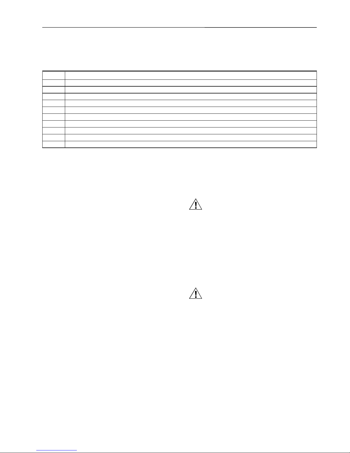
Hardware Overview
Fig. 1. Excel 50 Controller housing.
Fig. 2. Screw terminal blocks.
Fig. 3. Phoenix terminal blocks.
Fig. 4. Fuse, 4 A quick-acting (behind Terminal Block A)
12345
9678
PW3
M+ M-
On Short Slave
M+ M-
M-Bus
M+ M-
Power RS232C
V+ V- RX T X
Fig. 5. Application module. Fig. 6. Meter-Bus adapter.
Fig. 7. Mounting accessories.
Version Overview
Housing:
With Man-Machine-Interface (MMI)
Without MMI
Application Module:
Standalone (EPROM)
Standalone (Flash-EPROM)*
C-Bus (Flash-EPROM)*
C-Bus/serial port for Meter-Bus (Flash-EPROM)*
L
ONWORKS network (Flash-EPROM)*
C-Bus/L
ONWORKS network (Flash-EPROM)*
*Version can be upgraded by firmware. Firmware with
integrated modem communication is available for downloading to the controller.
Mounting:
Front door
Cabinet, front side facing DIN-rail
Cabinet, back side facing DIN-rail
Terminals:
Screw Terminal blocks
Phoenix Terminal blocks for flat strip cabling
Page 7
EXCEL 50 INSTALLATION INSTRUCTIONS
7 EN1B-0101
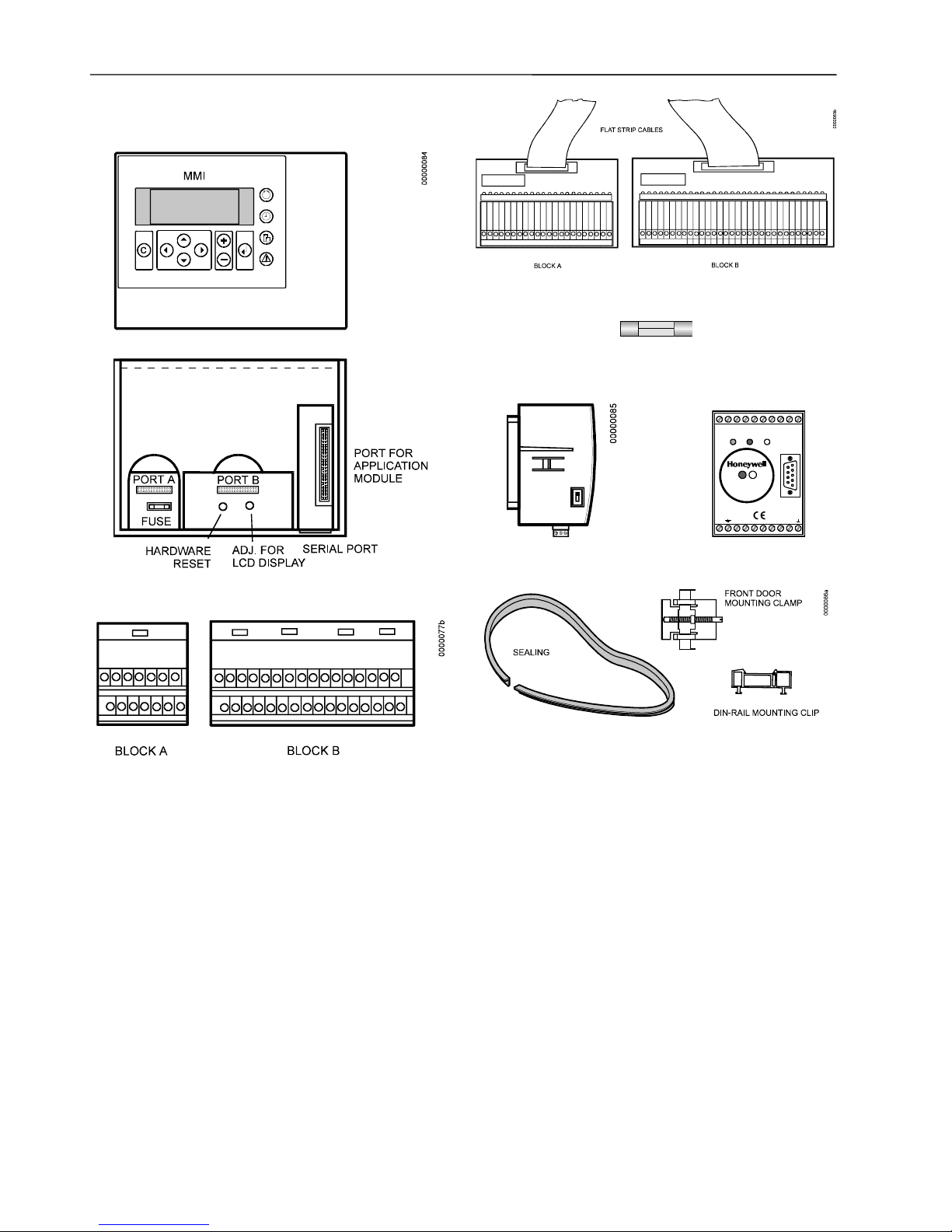
Dimensions
7.79 in. (198 mm)
5.90 in. (150 mm)
3.19 in. (81 mm)
2.76 in. (70 mm)
CUTOUT
7.32 in. (186 mm)
CUTOUT
5.43 in. (138 mm)
0000042a
PORT A PORT B
FUSE
HARDWARE
RESET
A
DJ. FOR
LCD DISPLAY
PORT FOR
APPLICATION
MODULE
2.83 in. (72 mm)
3.94 in. (100 mm)
A
PPLICATION
MODULE
C-BUS PORT
SERIAL -PORT
STANDARD DIN-CUTOUT
FAST ACCESS
KEYS
BASIC FUNCTION KEYS
LCD DISPLAY
1.34 in.
(34 mm)
1.34 in.
(34 mm)
3.34 in. (85 mm)
3.34 in. (85 mm)
DIN-RAIL
MOUNTING
CLIP
DIN-RAIL
MOUNTING
CLIP
3.82 in. (97 mm)
4.96 in. (126 mm)
4.17 in. (106 mm)
1
1
= DIN-rail clip position when installed
without MMI (connectors to front).
2
2
= DIN-rail clip position when installed
with MMI
(
MMI to front).
Fig. 8. Dimensions.
Page 8
EXCEL 50 INSTALLATION INSTRUCTIONS
EN1B-0101 8
MOUNTING
If the Excel 50 Controller has an MMI, the housing is
mounted either in the front door of a cabinet or on a DIN-rail
with the back facing to the DIN-rail.
The controller without an MMI is mounted on a DIN-rail with
the front facing to the DIN-rail.
Table 1. Mounting Versions.
MMI Version Where
mounted
Necessary accessory*
Front door Cutout in
front door
XL 50 ACC3 - Rubber
sealing ring and front door
mounting clamps
Yes
Inside cabinet DIN-rail DIN-rail mounting clips
No Inside cabinet DIN-rail DIN-rail Mounting clips
*The DIN-rail mounting clips are part of the delivery. The
Accessory kit XL 50 ACC3 for front door mounting must be
ordered separately.
Housing
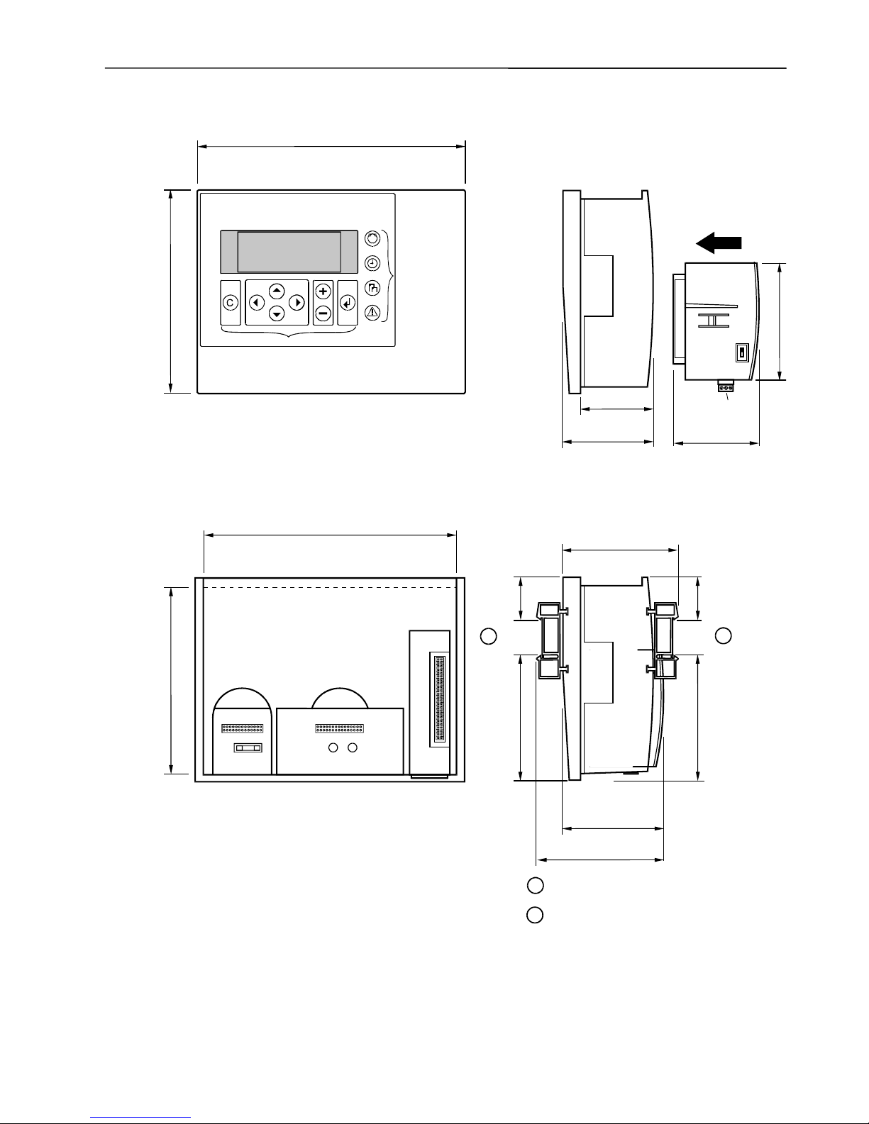
Front Door
1. Choose the position of the controller in the front door.
Observe the minimum and maximum distances to other
devices in the front door.
2. Cut a rectangle measuring 7-21/64 in. x 5-7/16 in.
(186 mm x 138 mm) out of the front door (standard DIN
cutout).
Fig. 9. Front door cutout dimensions.
3. Insert the rubber sealing ring into the gap around the
front plate of the Excel 50 Controller.
Fig. 10. Inserting sealing ring.
4. Insert the controller into the cutout in the front door.
Fig. 11. Inserting controller in front door cutout.
Page 9

EXCEL 50 INSTALLATION INSTRUCTIONS
9 EN1B-0101
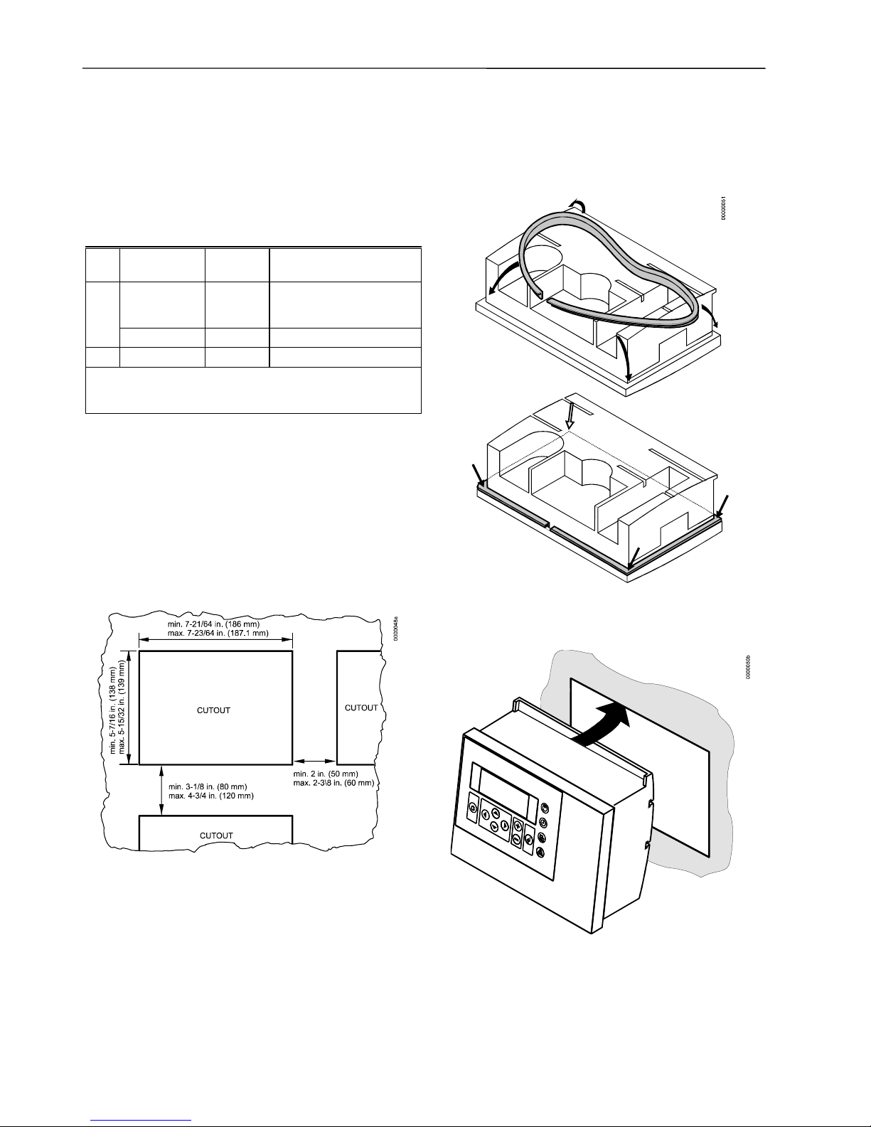
5. Attach Front Door Mounting clamps on both sides of
the controller and tighten the screws with a screwdriver
as is shown in Fig. 12.
Fig. 12. Fixing controller with front door
mounting clamps.
Inside Cabinet without MMI
1. Break plastic tabs covering the slots on the controller
for the DIN-rail mounting clips using a screwdriver.
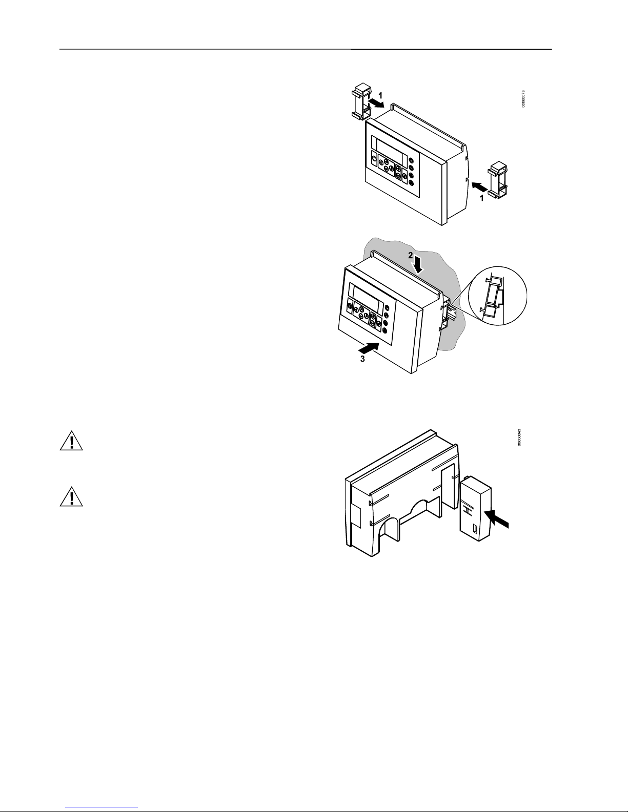
2. Attach the DIN-rail mounting clips to the housing as is
shown in Fig. 13.
3. Mount the controller on the DIN-rail as is shown in Fig.
13.
Fig. 13. Cabinet mounting without MMI.
Page 10
EXCEL 50 INSTALLATION INSTRUCTIONS
EN1B-0101 10
Inside Cabinet with MMI
The screw terminal blocks and the switch for the bus termination cannot be accessed after the controller with MMI is
mounted on the DIN-rail.
Although the Flat Strip cables and the Bus Terminal socket
can still be plugged in and unplugged, it is easier to do the
complete installation before mounting the controller on the
DIN-rail:
1. Plug in the application module as is shown in Fig. 14.
2. Read the complete chapter "Installation" carefully.
3. Depending on which terminal block type you have
chosen:
— Follow the instructions from chapter "Screw
Terminal Block Installation Procedure".
or
— Follow the instructions from chapter "Phoenix Ter-
minal Block Installation Procedure".
4. Optional: Connect the C-Bus to the application module
as described in chapter "C-Bus Connection Procedure"
and/or connect the application module serial port to the
Meter-Bus adapter as described in chapter “Meter-Bus
Connection Procedure”.
5. Break plastic tabs covering the slots on the controller
for the DIN-rail mounting clips using a screwdriver.
6. Attach the DIN-rail mounting clips at the housing as is
shown in Fig. 13.
7. Mount the controller on the DIN-rail.
Fig. 14. Cabinet mounting with MMI.
Application Module
CAUTION
Always plug in the application module before
connecting the power supply.
CAUTION
Always disconnect the power supply before
unplugging the application module.
— Plug in the application module until it snaps into the
controller housing.
Fig. 15. Plug-in of application module.
NOTE: If the application module has been replaced or
plugged out and in again, please push the Reset
button (behind I/O terminals) after power on.
Page 11
EXCEL 50 INSTALLATION INSTRUCTIONS
11 EN1B-0101
INSTALLATION
With the Excel 50, two different types of input/output terminals can be used: Screw terminal blocks for direct wiring
and Phoenix terminal blocks for remote wiring within the
same cabinet.
The installation procedures for the two types are different.
For proper installation, follow these instructions:
1. Read the complete chapter "Installation" carefully.
2. Depending on which terminal block type you have
chosen:
— Follow the instructions from the chapter "Screw
Terminal Block Installation Procedure".
or
— Follow the instructions from the chapter "Phoenix
Terminal Block Installation Procedure".
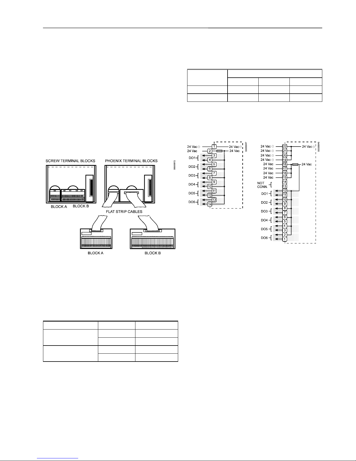
Fig. 16. Wiring options.
The two screw terminal blocks are attached directly to the
controller housing.
The Phoenix terminal blocks are connected to the controller
via flat strip cables. The use of Phoenix terminal blocks together with the flat strip cables will reduce the installation
effort as well as wiring mistakes.
Table 2. Terminal blocks.
Name Code No. of terminals
XS 50 Block A 14
Screw terminal block
XS 50 Block B 34
XSP 526 22
Phoenix terminal block
XSP 534 34
Table 3. Flat Strip Cables.
Length
For Phoenix
terminal block
5 ft (1.5 m) 8 ft (2.5) m 11 ft (3.5 m)
XSP 526 XW 572 XW 573 XW 574
XSP 534 XW 575 XW 576 XW 577
Terminal Details
Block A
Fig. 17. Screw Terminal
Block A.
Fig. 18. Phoenix Terminal
Block A.
Page 12
EXCEL 50 INSTALLATION INSTRUCTIONS
EN1B-0101 12
Block B
A01
A02
A03
A04
DI1
DI2
DI3
DI4
AI1
AI2
AI3
AI4
AI5
AI6
AI7
AI8
+10V/5mA REF.
DI-POWER
AGND
GND
00000
046
15
17
19
21
23
25
27
29
31
33
35
37
39
41
43
45
47
16
18
20
22
24
26
28
30
32
34
36
38
40
42
44
46
48
Fig. 19. Screw Terminal
Block B.
1
2
3
4
5
6
7
8
9
10
11
12
13
14
15
16
17
18
19
20
21
22
23
24
25
26
27
28
29
30
31
32
33
34
A01
A02
A03
A04
DI1
DI2
DI3
DI4
AI1
AI2
AI3
AI4
AI5
AI6
AI7
AI8
A
GND
GND
00000
0
44
+10V/5mA REF.
DI-POWER
Fig. 20. Phoenix Terminal
Block B.
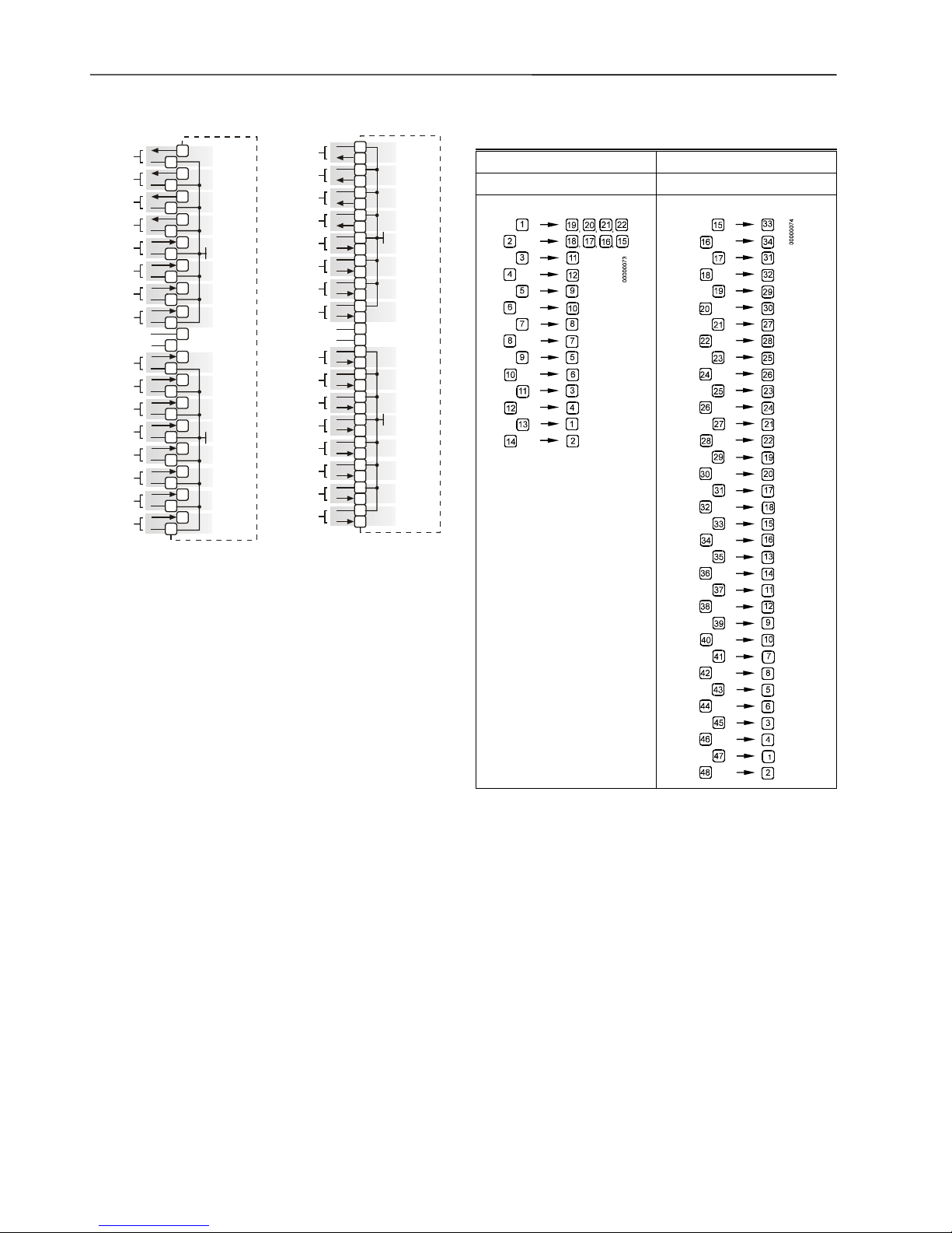
IMPORTANT
The numbering of the Phoenix terminals differs completely from the screw terminal numbering. Using
screw terminal blocks will be the more common
solution. Therefore, in the following connection
examples, only the connections for screw terminal
blocks are shown. Refer to Table 4 when using
Phoenix terminal blocks.
Table 4. Translation table for screw to Phoenix
terminal numbering.
Block A Block B
Screw Phoenix Screw Phoenix
Page 13

EXCEL 50 INSTALLATION INSTRUCTIONS
13 EN1B-0101
Cabling
Cable Routing
All signal (input/output, low voltage) cables are communication circuits in accordance with VDE 0100, VDE 0800 and
local regulations and should therefore be routed separately
from line voltage.
Table 5. Minimum Distances to Line Voltage.
Cable Type Minimum Distance
unshielded cable 4 in. (100 mm)
shielded cable 3/8 in. (10 mm)
IMPORTANT
Avoid joining sensor cables.
Shielding
Fig. 21. Sensor shielding.
Shielding of sensor and actuator cables with low protective
voltages is not necessary if the general guidelines on cable
routing are observed (see "Cable Routing", page 13). If these
guidelines cannot be observed, shielded cable must always
be used. The shielded cable must be grounded as is shown
in Fig. 21.
IMPORTANT
Shielding of I/O cables that are connected to
peripherals such as sensors and actuators must be
grounded at the control cabinet side only in order to
avoid ground loops.
All Honeywell actuators are RFI suppressed in accordance
with VDE 0871/B and VDE 0875/N.
Lightning Protection
Please check with your local Honeywell representative for
information on lightning protection.
Cable Lengths and Cross Sectional Areas
Table 6. Signal types and cross-sectional areas.
Cross-sectional areaType of signal
≤≤≤≤ 300 ft
(100 m)
≤≤≤≤ 550 ft
(170 m)
≤≤≤≤ 1,300 ft
(400 m)
Power supply
(24 Vac)
≤ 16 AWG
(≥ 1.5 mm
2
)
≤ 14 AWG
(≥ 2.5 mm2)
-
Low-current
signals*
≤ 20 AWG (≥ 0.5 mm2)
*E.g. for 0-10 V sensors, totalizers, digital inputs, 0-10 V
signals for actuators.
IMPORTANT
The maximum length of a signal cable with 24 Vac
supply is 550 ft (170 m). The maximum length of a
two-wire, 0 to 10 Vdc signal cable is 1,300 ft
(400 m). The secondary side of the transformer must
not be connected to earth ground.
TRANSFORME R
MAX. 550 ft (170 m)
MIN. 14 AWG
(
2.5 mm
)
2
PRIMARY
VOLTAGE
Y
GND
24 Vac
2
24 V
1
0000056
b
Fig. 22. Cabling of actuator with 24 Vac supply and
max. 550 ft (170 m).
If the distance between the controller and actuator or sensor
with 24 Vac supply is greater than 550 ft (170 m), a separate
external transformer for the actuator or sensor is necessary.
TRANSFORM ER
EXTERNAL
TRANSFORMER
PRIMARY
VOLTAGE
MAX. 1300 ft (400 m)
MIN.20 AWG (0.5 mm )
2
24 Vac
230 Vac
120 Vac
230 Vac
120 Vac
0 TO 10 Vdc
GND
PRIMARY
VOLTAGE
24 Vac
00000057d
2
1
Fig. 23. Cabling of actuator with 24 Vac supply from
external transformer and max. 1,300 ft (400 m).
IMPORTANT
We recommend installing a fuse on the secondary
side of the transformer in order to protect the devices
against miswiring.
Page 14

EXCEL 50 INSTALLATION INSTRUCTIONS
EN1B-0101 14
Analog Inputs
Technical Description
The analog inputs convert data from passive sensors and
active sensors with voltage output. The analog inputs can be
used as current inputs for active sensors, but then an external resistor parallel to the sensor is necessary. It is also
possible to feed digital signals to the analog inputs.
Technical Specification
Number:
Eight analog inputs
Types of input signals:
NTC 20k ohms
0 to +10 V (max. +11 V)
0 (4) to 20 mA (with an external resistor of 499 ohms
±0.25% [see Fig. 24])
Each input is switched automatically via software either as
input for NTC 20k ohms (high impedance) or voltage source
0 to +10V (max. +11V, low impedance).
NTC 20k ohms:
Range -58 °F to +302 °F (-50 °C to
+150 °C)
Voltage source:
Range 0 to 10 V
IMPORTANT
The analog inputs are protected against short circuit
and overvoltage up to 24 Vac and 40 Vdc. If any
input is sourced with more than 40 Vdc or negative
voltage, the other inputs will be influenced. This
could result in wrong values.
Sensors and Transducers
A
GND
0000006
1
31
33
35
37
39
41
43
45
47
32
34
36
38
40
42
44
46
48
A
I1
A
B
C
AI6A
I8
R1
A
CTIVE
SENSOR
TRANSFOR MER FOR
ACTIVE SENSOR
1
2
0-10V
0(4) to
20 mA
499
0.25
%
SENSOR
NTC 20 k
AI2AI3AI4AI5A
I7
4 33
3
2
34
31
SAF25
0 - 5 V
I = 1 mA
10 33
11
12
34
31
VMP
0 - 10 V
I = 1 mA
10 Vdc
max. 5 mA
Fig. 24. Analog inputs, sensor connections.
Passive sensors (NTC 20k ohms)
Room temperature sensor RF 20
Inlet temperature sensor VF 20A
External temperature sensor AF 20
Active sensors (0 to 10V):
Duct Humidity Sensor H7011A1000
Duct Humidity Sensor H7012A1009
Active sensors (0 (4) to 20 mA):
Immersion temperature sensor VF 100
Air duct temperature sensor LF 100
Wind sensor:
Wind sensor WS21
Further connections:
Temperature sensor terminal TF26
Solar Sensor SAF 25
VMP Feedback Potentiometer
The characteristic curves for other types of sensors can be
entered manually in the data point description (see Excel 50
User Guide, EN2B-137).
Page 15

EXCEL 50 INSTALLATION INSTRUCTIONS
15 EN1B-0101
Firmware Release 2.03.xx and older
L
N
A
GND
00000
62a
31
NORMALLY OPEN
230 Vac/ 50 Hz
120 Vac/ 60 Hz
230 Vac/ 50 Hz
120 Vac/ 60 Hz
L
N
NOT CONNECTED
NORMALLY OPEN
NOT CONNECTED
NORMALLY CLOSED
10 Vdc
max. 10 mA
32
33
34
35
36
37
38
39
40
41
42
43
44
45
46
47
48
AI1
AI3AI6A
I8
AI4
AI2AI7A
I5
Fig. 25. Analog inputs used as digital inputs.
For normally open contacts, a digital signal must be switched
via the changeover contact of an additional relay.
Unconnected analog inputs have a default voltage of 8.5 V.
This is interpreted by the controller as a logical 1. This means
that, in general, no external relay is needed for normally open
contacts.
IMPORTANT
The relay contact must be suitable for switching low
voltage. For long cable distances, the analog input
signal may be sensitive to interference. In this case,
an external relay may also be used for normally
closed contacts.
Firmware Release 2.04.xx
L
N
A
GND
00000
6
2m
31
POWER
10 Vac
230 Vac/ 50 Hz
120 Vac/ 60 Hz
230 Vac/ 50 Hz
120 Vac/ 60 Hz
L
N
NOT CONNECTED
NORMALLY CLOSED
NOT CONNECTED
NORMALLY OPEN
10 Vdc
max. 10 mA
32
33
34
35
36
37
38
39
40
41
42
43
44
45
46
47
48
AI1
AI3AI6A
I8
AI4
31
AI2
31
A
I7
Fig. 26. Analog inputs used as digital inputs.
Table 7. Accuracy of analog inputs with NTC sensors
Range Deviation / ± Kelvin
(without sensor tolerance)
NTC (20k ohms)
-58 to <-40°F (-50 to <-40°C) ≤ 5.5 K
-40 to <-22°F (-40 to <-30°C) ≤ 3.0 K
32 to <-4°F (-30 to <-20°C) ≤ 1.8 K
86 to <14°F (-20 to <-10°C) ≤ 1.1 K
158 to <32°F (-10 to <0°C) ≤ 0.8 K
212 to <50°F (0 to <10°C) ≤ 0.6 K
266 to <122°F (10 to <50°C) ≤ 0.4 K
266 to <158°F (50 to <70°C) ≤ 0.6 K
266 to <194°F (70 to <90°C) ≤ 1.0 K
266 to <212°F (90 to <100°C) ≤ 1.5 K
266 to <248°F (100 to <120°C) ≤ 2.4 K
266 to <302°F (120 to <150°C) ≤ 5.3 K
Page 16

EXCEL 50 INSTALLATION INSTRUCTIONS
EN1B-0101 16
Digital Inputs
Technical Description
Fig. 27. Input switching voltages.
The digital inputs signals can be DC voltage signals. If an
input voltage is higher than 5 V, the digital signal switches to
logic "1" status. With a hysteresis of 2.5 V, the input signal
must fall below 2.5 V before the digital status switches to
logic "0".
Three out of four digital inputs can be used as totalizers.
Beginning with V2.04.00 firmware, the online point attribute
Normally Open / Normally Closed (NO/NC) defines the
relation between the physical state (open/closed) and its
logical status. See Table 8.
Technical Specification
Number:
4 digital inputs
Type of signals:
DC signal max. 24 Vdc
Input resistance:
10k ohms
IMPORTANT
The digital inputs are protected against short circuit
and overvoltage up to 24 Vac and 40 Vdc.
Parameter requirements:
If the digital inputs are used for normal digital or analog
signals, the signals have to meet the static and dynamic
requirements stated in Table 8 and Table 9.
If three out of four digital inputs are used as totalizers, the
signals at the totalizer inputs have to fulfill the static and
dynamic requirements stated in Table 8 and Table 10 while
the signal at the fourth input has to meet only the static requirements of Table 8.
Table 8. Static Parameters of Digital Inputs.
Contact
Position
NO/NC
attribute
Logical
Status
Input Voltage
Open NO 0 ≤ 2.5 V
Closed NO 1 ≥ 5 V
Open NC 1 ≤ 2.5 V
Closed NC 0 ≥ 5 V
Table 9. Dynamic Parameters of Digital Inputs.
Frequency Pulse
duration
Pause
interval
Bounce
time
max. 0.4 Hz min. 1.25 s min. 1.25 s max. 50 ms
Table 10. Dynamic Parameters of Totalizers.
Frequency Pulse
duration
Pause
interval
Bounce
time
max. 15 Hz min. 20 ms min. 30 ms max. 5 ms
Connection Examples
Fig. 28. Digital inputs, connection examples.
Page 17

EXCEL 50 INSTALLATION INSTRUCTIONS
17 EN1B-0101
Analog Inputs
Technical Description
Analog outputs can be used, for example, to operate valve or
damper actuators. The characteristic curves for these
actuators can be defined via MMI (see Excel 50 User Guide).
Each analog output can also be used as a digital output.
Technical Specification
Number:
Four analog outputs
Analog output details:
Voltage 0 to 10 V, max. 11 V
Current max. 1 mA
Resolution 8-Bit
Min. step: 0.043 mV
Accuracy ±100 mV ±1 digit
Relay Modules
The relay modules facilitate the control of peripheral devices
with high load via the analog outputs of the controller. The
connection examples (for the relay modules MCD 3 and
MCE 3) are shown here.
IMPORTANT
The external supply of the relay modules must be
24 Vac, the same as of the supply of the controllers.
The analog outputs are protected against
overvoltage up to 24 Vac and 35 Vdc.
Supply:
Several relay modules can be connected in series via the
bridged terminal pair:
24 Vac: Terminals 11/12 of the relay
24 Vac (-): Terminals 13 to 16 of the relay
Fig. 29. Analog outputs, connection of relay MCD 3.
MCD 3:
Relay terminal 17 controls the changeover contact K3.
Relay terminal 18 controls the ON contacts K1, K2.
Ground can be looped through terminals 2/3.
Fig. 30. Analog outputs, connection of relay MCE 3.
MCE 3:
Relay terminal 16 controls the ON contact K3.
Relay terminal 17 controls the changeover contact K2.
Relay terminal 18 controls the changeover contact K1.
Page 18

EXCEL 50 INSTALLATION INSTRUCTIONS
EN1B-0101 18
Digital Outputs
Technical Description
The digital outputs are switched by a triac that can be
connected directly to an external relay.
Technical Specification
Number:
Six digital outputs
Output stages:
Low signal 0 V
High signal 24 Vac
Type Close, only
Load:
Per output min. 0.01 A
max. 0.8 A
Total max. 2.4 A
Cos ϕ 0.5 to 1
IMPORTANT
The digital outputs are protected against short
circuit current via internal fuse, but they are not
protected against overload. All digital outputs are
protected via one fuse, only; if any digital output is
short-circuited, the fuse will be blown and will
interrupt the main power. In that case, the controller does not work. If the CPU is running into the
WATCHDOG caused by a software or hardware
error, all digital outputs will be set to low signal,
which means all digital outputs are inactive.
Beginning with V2.04.00 firmware, the online point attribute
Normally Open / Normally Closed (NO/NC) defines the
relation between the physical state (relay on/off) and its
logical status. See Table 11.
Table 11. Digital Output Parameters.
Relay
ON/OFF
NO/NC
attribute
Logical
Status
Output
Voltage
On NO 1 24V
Off NO 0 0V
On NC 0 0V
Off NC 1 24V
Connection Examples
Fig. 31. Digital outputs, connection of relay.
Fig. 32. Digital outputs, direct connection of 3-position
actuators.
Page 19

EXCEL 50 INSTALLATION INSTRUCTIONS
19 EN1B-0101
Power Supply
The Excel 50 Controller is powered by an external transformer.
Transformer requirements for one Excel 50 Controller:
Voltage 24 Vac ±20%
Current 3 A, if fully equipped (6 DO's x 0.4 A)
2 A, if current of DO's does not exceed 1.8 A
Power 72 VA, if fully equipped
The transformer, already installed in the cabinet, can be used
to supply several controllers, communication devices or peripherals like actuators, etc. if the transformer provides
sufficient power.
Fig. 33. Transformer example.
CRT-Series
Table 12. Number of controllers connected to one
transformer.
Transformer Controller Excel 50
CRT 2 1 (1.8A max.)
CRT 6 2
CRT 12 4
Use quick-acting backup fuse 10 A (or automatic H16 or L16)
to protect transformer primary side. On the primary side of
the CRT 2, there is a fusible output of type M 0.315 A (T)
250 V for the purpose of fine fusing.
Table 13. Overview of CRT Series AC/DC current.
Transformer max. AC current max. DC current
CRT 2 2 A 0.5 A = 500 mA
CRT 6 6 A 1.3 A = 1300 mA
CRT 12 12 A 2.5 A = 2500 mA
Fig. 34. AC/DC current graphs.
1450 Series
All transformers of the 1450 series are designed for 50/60 Hz
AC and have insulated accessory outputs. The transformers
include built-in fuses, line transient/surge protection and AC
convenience outlets and meet NEC class 2 requirements.
Table 14. 1450 Series transformers.
Part #
1450 7287
Primary Side Secondary Side
-001 120 Vac 24 Vac, 50 VA
-002 120 Vac 2 x 24 Vac, 40 VA and
100 VA from separate
transformer
-003 120 Vac 24 Vac, 100 VA and
24 Vdc 600 mA
-004 240/220 Vac 24 Vac, 50 VA
-005 240/220 Vac 2 x 24 Vac, 40 VA and
100 VA from separate
transformer
-006 240/220 Vac 24 Vac, 100 VA and
24 Vdc 600 mA
Standard Transformers
Standard commercially available transformers must fulfill the
following specifications:
Table 15. Requirements for Standard Transformers.
Output voltage Impedance AC current
24.5 Vac to 25.5 Vac ≤ 1.15 ohms max. 2 A
24.5 Vac to 25.5 Vac ≤ 0.40 ohms max. 6 A
24.5 Vac to 25.5 Vac ≤ 0.17 ohms max. 12 A
Page 20

EXCEL 50 INSTALLATION INSTRUCTIONS
EN1B-0101 20
Screw Terminal Block Installation
1. Make sure that the power supply of the cabinet is
disconnected.
2. Make sure that the power supply of the cabinet is
disconnected and the application module is plugged in
the housing.
3. Choose the minimum cross sectional areas for all
cables to and from sensors, actuators, valves, relays,
etc. you want to connect to the Excel 50 Controller from
Table 6.
4. Connect sensors, transducers, etc. to the analog input
terminals.
Fig. 35. Connecting a cable to a screw terminal.
IMPORTANT
When installing a separate external transformer, do
not connect the cabinet ground to the controller
system ground.
5. If the distance between the controller and an actuator
or sensor with 24 Vac supply is greater than 550 ft
(170 m):
a) Choose a transformer from the transformers listed
in chapter "Power Supply".
b) Connect the chosen transformer directly to the
actuator or sensor.
6. Connect sensors, transducers, etc. to the digital input
terminals.
7. Connect valves, actuators, relays, etc. to the analog
output terminals.
8. Connect relays, actuators etc. to the digital output
terminals.
9. Select one of the transformers of the CRT series or
1450 series from the Table 13 or Table 14 or take a
commercially available standard transformer fulfilling
the requirements from Table 15.
10. Make sure that the application module is attached to
the controller housing.
WARNING
High Voltage
Risk of death or electrical shock.
— Do not connect line power supply directly to the
terminals.
— Insulate devices with 120 Vac / 230 Vac by a
transformer.
IMPORTANT
The transformer feeding the Excel 50 Controller
must be in the same cabinet. For the selection of the
transformer the max. DC current must be considered
if field devices with DC load are used.
The secondary side of the transformer must not be
connected to earth ground.
11. Connect the 24 Vac (-) on the secondary side of the
transformer to terminal 1 on Screw Terminal block A.
12. Connect the 24 Vac on the secondary side of the
transformer to terminal 2 on Screw Terminal block A.
Fig. 36. Connecting the power supply.
IMPORTANT
If there already are additional transformers, for
example supplying actuators or active sensors:
— Connect the 24 Vac (-) (secondary side) of the
transformers together.
13. Attach the terminal blocks to the housing as is shown in
Fig. 37.
Fig. 37. Attaching of screw terminal blocks.
Page 21

EXCEL 50 INSTALLATION INSTRUCTIONS
21 EN1B-0101
Phoenix Terminal Block Installation
IMPORTANT
The numbering of the Phoenix terminals differs completely from the screw terminal numbering which is
shown in the connection example figures. Translate
the terminal numbers from screw terminal blocks to
Phoenix terminal blocks according to Table 4.
1. Mount Phoenix terminal blocks on DIN-rail as is shown
in Fig. 38.
Fig. 38. Mounting the Phoenix terminal blocks.
2. Make sure that the power supply of the cabinet is
disconnected.
3. Make sure that the application module is plugged in the
housing.
4. Choose the minimum cross sectional areas for all
cables to and from sensors, actuators, valves, relays,
etc. you want to connect to the Excel 50 Controller from
Table 6.
5. Connect sensors, transducers, etc. to the analog input
terminals.
Fig. 39. Connecting a cable to a Phoenix terminal.
IMPORTANT
When installing a separate external transformer, do
not connect the cabinet ground to the controller system ground.
6. If the distance between the controller and an actuator
or sensor with 24 Vac supply is greater than 550 ft (170
m):
a) Choose a transformer from the transformers listed
in chapter "Power Supply" (page 15).
b) Connect the chosen transformer directly to the
actuator or sensor.
7. Connect sensors, transducers, etc. to the digital input
terminals.
8. Connect valves, actuators, relays, etc. to the analog
output terminals.
9. Connect relays, actuators etc. to the digital output
terminals.
10. Select one of the transformers of the CRT series or
1450 series from Table 13 or Table 14 or take a
commercially available standard transformer fulfilling
the requirements from Table 15.
11. Make sure that the application module is attached to
the controller housing.
WARNING
High voltage
Risk of death or electrical shock.
— Do not connect line power supply directly to the
terminals.
— Insulate devices with 120 Vac / 230 Vac by a
transformer.
IMPORTANT
The transformer feeding the Excel 50 Controller
must be in the same cabinet.
For the selection of the transformer, the max. DC
current must be considered if field devices with DC
load are used.
The secondary side of the transformer must not be
connected to earth ground.
12. Connect the 24 Vac (-) on the secondary side of the
transformer with the system ground to all of the terminals 19 to 22 on Phoenix Terminal block A.
13. Connect the 24 Vac on the secondary side of the
transformer with the system ground to all of the terminals 15 to 18 on Phoenix Terminal block A.
Page 22

EXCEL 50 INSTALLATION INSTRUCTIONS
EN1B-0101 22
Fig. 40. Connecting the power supply.
IMPORTANT
If there already are additional transformers, for
example supplying actuators or active sensors:
— Connect the 24 Vac (-) (secondary side) of the
transformers together.
14. Plug the flat strip cables into the sockets of the terminal
blocks and the housing as is shown in Fig. 41.
IMPORTANT
Make sure pins match properly with their sockets
when mating connectors.
Fig. 41. Plug-in of flat strip cables.
Adjusting the MMI Display Contrast
Front Door Mounted with MMI
1. Unplug the screw terminal block B or Flat Strip cable to
Port B while the controller is connected to the power
supply.
2. Adjust the display contrast with a slotted screwdriver or
a cross-tip screwdriver.
Fig. 42. Adjusting the display contrast.
3. Attach screw terminal block B or connect Flat Strip
Cable to Port B.
DIN-rail Mounted with MMI
1. Unmount the controller from the DIN-rail.
2. Unplug the screw terminal block B or Flat Strip cable to
Port B while the controller is connected to the power
supply.
3. Adjust the display contrast with a slotted screwdriver or
a cross-tip screwdriver as is shown in Fig. 42.
4. Attach screw terminal block B or connect Flat Strip
Cable to Port B.
5. Mount the controller on the DIN-rail again.
Page 23

EXCEL 50 INSTALLATION INSTRUCTIONS
23 EN1B-0101
COMMUNICATION
The Excel 50 Controller has the capability to communicate
with the Excel Building Supervisor (XBS) and other
EXCEL 5000 devices via the C-Bus. The Excel 50 Controller
also has the capability to communicate with devices on a
L
ONWORKS network. A further communication option is con-
nection to a Meter-Bus. All communications options are dependent upon the application module, and not all options are
available on one module (see Table 16).
A modem/ISDN terminal adapter may be connected to Flash
EPROM versions with V2.01.00 software or newer to allow
remote communication with the controller.
Table 16. Application Module Versions.
Module model Module type
XD50-E Standalone
XD50-F Standalone/Flash EPROM
XD50-FC C-Bus/Flash EPROM
XD50-FCS C-Bus/Meter-Bus/Flash EPROM
XD50-FL LONWORKS BUS/Flash EPROM
XD50-FCL C-Bus/LONWORKS BUS/Flash EPROM
XD52-FC C-Bus/Flash EPROM (Large RAM)
XD52-FCS C-Bus/Flash EPROM (Large Ram),
Meter-Bus
NOTE: EPROM versions can be upgraded by direct firm-
ware download via serial port or C-Bus.
IMPORTANT
Electrostatic discharge can damage the application
module. Always disconnect the power supply when
plugging in and unplugging the application module.
C-Bus
C-BUS
LEDs
SHIELD
C +
C -
C-BUS TxD, YEL
POWER, GRN
C-BUS RxD, YEL
RESERVED
RESERVED
C-BUS
TERMINATION
SWITCH
000
0060c
45
6
Fig. 43. C-Bus connection and LEDs.
Up to 30 controllers can communicate with one another and
the Excel Building Supervisor PC (XBS) via the C-Bus.
Instead of an Excel 500/600 Controller, other C-Buscompatible components can also be connected (Excel IRC
Multicontroller; Excel EMC; Modem Device XM 100A).
C-Bus Termination
Fig. 44. DIP Switch settings for C-bus.
The application module is equipped with a DIP switch for the
C-Bus to set the bus termination appropriate for the communication speed.
Table 17. DIP Switch Settings for C-Bus Termination.
DIP Switch
setting
Communication
speed (max.)
Controller
Location
Compatibility
up 9.6 Kbaud - XD505A,
XL20XD
middle 76.8 Kbaud middle of
bus
XD508,
XL20XD508
down 76.8 Kbaud beginning or
end of bus
XD508,
XL20XD508
NOTE: Modules listed in Compatibility column are used in
Excel 20/100B/500/600 Controllers.
NOTE: The controllers with the termination need to be
switched on prior to the controllers in the middle of
the C-Bus. The C-Bus may not work if the controllers
with termination are switched off.
Cable Specification
The maximum cable length is 4,000 ft (1,200 m). There are
regional differences as to whether shielded or unshielded
cable must/can be used.
IMPORTANT
In Europe, only shielded cable is permitted while in
the US, shielded or unshielded cable can be used.
Inside the cabinet:
J-Y-(ST)Y 2 x 2 x 0.8
Outside the cabinet:
A-Y-(ST) 2 x 2 x 0.8
In principle, data transmitting cables should be shielded in
case of RFI.
Page 24

EXCEL 50 INSTALLATION INSTRUCTIONS
EN1B-0101 24
Table 18 summarizes cable types and gives selection
guidance. Note that baud rate and maximum bus length are
related to each other.
Table 18. C-Bus Cable Types.
Cable type Description Recommended for
J-Y-(ST)Y
2 x 2 x 0.8
shielded,
twisted pair
Europe
Inside cabinet
A-Y-(ST)Y
2 x 2 x 0.8
shielded,
twisted pair
Europe
Outside cabinet
AK 3702 unshielded,
twisted pairUSnot approved for Europe
AK 3740A shielded US (low-cost)
not approved for Europe
Belden 9842 twisted pair Europe
US also possible
Belden 9841 shielded US
AK 3702 unshielded,
twisted pairUSnot approved for Europe
AK 3740A shielded US (low-cost)
not approved for Europe
Each end of the shield on the C-Bus should be connected to
the shield terminal of the respective device. Do not connect it
to the cabinet ground or any other ground points.
C-Bus Extension by Using Repeaters
The C-Bus length can be extended by using repeaters. Each
repeater extends the bus length by 4,000 ft (1,200 m).
For the US the repeater is available either with or without
housing. In Europe, only the version with housing is allowed.
Table 19. Ordering No. for Repeaters.
Description US
Ordering No.
European
Ordering No.
without housing 14507324-001 -
with housing 14507324-002 XD 509
C-Bus Connection Procedure
1. Choose a suitable C-Bus cable from Table 18.
IMPORTANT
Make sure that all bus devices connected to the
same C-Bus are set to the same baud rate otherwise
proper communication cannot be ensured.
2. Set the DIP switch according to Table 17.
IMPORTANT
The C-Bus must be connected through the individual
controllers (open ring). Star connection is not permitted because uncontrollable line reflections could
occur.
3. Connect the cable shield to C-Bus terminal 4 (Fig. 45).
4. Connect the C+ cable to C-Bus terminal 5 (Fig. 45).
5. Connect the C- cable to C-Bus terminal 6 (Fig. 45).
6. If the maximum C-Bus length for the chosen cable
(Table 18) is exceeded:
— Use repeaters to extend to the maximum C-Bus
length (see section "C-Bus Extension by Using
Repeaters").
It may take up to two minutes to re-initialize the bus when
adding or removing a controller to/from the C-Bus. During
this time, communication on the C-Bus is lost.
Page 25

EXCEL 50 INSTALLATION INSTRUCTIONS
25 EN1B-0101
LONWORKS Network Interface
Excel 50 Controllers may be equipped with an application
module (see Table 15) containing an FTT-10A Free Topology
Twisted Pair Transceiver which allows communication with
other device on a L
ONWORKS network. FTT-10A transceivers
communicate at 78 Kbaud and provide transformer isolation
so that the bus wiring does not have a polarity; that is, it is
not important which of the two bus terminals are connected
to each wire of the twisted pair.
LEDs
C-BUS TxD, YEL
POWER, GRN
C-BUS RxD, YEL
LON SERVICE, RED
RESERVED
00000124
C-BUS
SHIELD
C +
C -
45
6
LON
BUS
NOT USED
A1
A2
12
3
LON SERVICE BUTTON
C-BUS
TERMINATION
SWITCH
Fig. 45. LonWorks network connection.
FTT devices can be wired in daisy chain, star, loop or any
combination thereof as long as the maximum wire length requirements given below are met. The recommended configuration is a daisy chain with two bus terminations. This
layout allows for maximum bus length, and its simple structure presents the least number of possible problems, particularly when adding on to an existing bus.
NOTE: A doubly-terminated bus may have stubs of up to
10 ft (3 m) from the bus to each node.
Table 20. Doubly-terminated bus specifications.
Cable Type Max. bus length
Belden 85102 2,700 m (8,900 ft)
Belden 8471 2,700 m (8,900 ft)
Level IV, 22 AWG 1,400 m (4,600 ft)
JY (St) Y 2x2x0.8 900 m (3,000 ft)
TIA568A Categ. 5 24AWG, twisted pair 900 m (3,000 ft)
NOTES:
The cable types listed above are as recommended by
Echelon in their FTT-10A User Guide. The cable recommended by Honeywell is the level IV, 22 AWG, solid
core, nonshielded cable. Belden part numbers are
9H2201504 (plenum) and 9D220150 (non-plenum).
The FTT specification includes two components that must be
met for proper system operation. The distance from each
transceiver to all other transceivers and to the termination
must not exceed the maximum node-to-node distance. If
multiple paths exists, the maximum total wire length is the
total amount of wire used.
Table 21. Free topology (singly-terminated)
specifications.
Cable type
Maximum nodeto-node distance
Maximum total
wire length
Belden 85102 1,650 ft (500 m) 1,650 ft (500 m)
Belden 8471 1,300 ft (400 m) 1,650 ft (500 m)
Level IV, 22AWG 1,300 ft (400 m) 1,650 ft (500 m)
JY (St) Y 2x2x0.8 1,050 ft (320 m) 1,650 ft (500 m)
TIA568A Category 5
24AWG, twisted pair
825 ft (250 m) 1,500 ft (450 m)
IMPORTANT
Do not use different wire types or gauges on the
same L
ONWORKS network segment. The step change
in line impedance characteristics would cause
unpredictable reflections on the network.
NOTE: In the event that the limit on the total wire length is
exceeded, then FTT physical layer repeaters
(FTT 10A) can be added to interconnect segments
and increase the overall length by an amount equal
to the original specification for that cable type and
bus type for each repeater used. For example,
adding repeaters for a doubly-terminated bus using
JY (St) Y 2x2x0.8 cable increases the maximum
length 3,000 ft (900 m) for each repeater.
LONWORKS Bus Termination
One or two Termination Modules, part no. 209541B, are required for a L
ONWORKS Bus with FTT devices on it, de-
pending upon the configuration. The maximum lengths described in the previous section must be adhered to for either a
daisy chain or free topology L
ONWORKS network layout. See
Fig. 46 and Fig. 47 for connection details for the 2095401B
Termination Module.
Fig. 46. Termination Module connections for doubly-
terminated FTT network.
Fig. 47. Termination Module connections for a singly-
terminated FTT network.
(op
tional
)
Page 26

EXCEL 50 INSTALLATION INSTRUCTIONS
EN1B-0101 26
LONWORKS Service LED Diagnostics
The LONWORKS service LED is used to diagnose the state of
the Excel 50 controller. In general:
— The controller is applicationless if the LED illuminates
continuously*
— The controller has an application but it is not configured
if the LED is blinking
— The controller is running normally if L2 is off
The L
ONWORKS service LED is located on the application
module (see Fig. 45).
Pushing the L
ONWORKS service button will force a new
commissioning of the Excel 50. While commissioning, LED
L2 continuously illuminates red for less than 1 minute and
afterwards return to the normal state (L2 = OFF).
A more detailed diagnosis can be carried out by observing
the duration of the ON and OFF states of the service LED in
connection with power ON / OFF. The following figure
illustrates the different service LED behaviors. These are the
most common behaviors, but others are possible since the
state of the service LED is under firmware control and can be
affected both by hardware and software anomalies.
Fig. 48. LONWORKS Service LED behaviors.
The following table describes each of the behaviors shown in
the previous figure under different contexts. Again, this list is
not exhaustive and therefore does not provide explanations
for every possible service LED behavior.
Table 22. L
ONWORKS Service LED behavior descriptions.
Behavior Context Likely Explanation
1 Power-up of the node Bad node hardware.
2 Power-up of the node Bad node hardware.
3 Power-up / Reset of the node The controller is applicationless. May be caused by the Neuron chip firmware
when a mismatch occurs on application checksums. This behavior is normal if
the application was exported to come up applicationless.
4 Anytime Possible corrupt EEPROM. For a Neuron 3150 Chip-based node, use a newly
programmed PROM, or EEBLANK and follow bring-up procedure.
5 Anytime The controller is unconfigured.
6 First power-up, Applicationless
firmware state exported
The OFF duration is approximately 1 second. Service LED should then turn
ON and stay on indicating an applicationless state.
6 First power-up, Unconfigured
firmware state exported
The OFF duration is 1-15 seconds depending on the application size and
system clock. Service LED should then begin flashing as in behavior 5,
indicating an unconfigured state.
6 First power-up, Configured
firmware state exported
The OFF duration is indefinite (1-15 seconds to load internal EEPROM; stays
OFF indicating configured state.) The controller is configured and running
normally.
7 Anytime The controller is configured and running normally.
Page 27

EXCEL 50 INSTALLATION INSTRUCTIONS
27 EN1B-0101
Controller Serial Port
Fig. 49. Serial port.
The serial port has a 9-pin sub-D connector and has a default
communication speed of 9.6 Kbaud.
Table 23. Signals of Serial Port.
Signal type Controller output Controller input
Signal ground
Transmit x
Receive x
Carrier detect x
Clear to send x
Data terminal ready x
5V x
MMI Connection
For direct communication the external operator interface
XI582 and the PC-based MMI XI584 can be connected to the
serial port.
When the cable from XI582 or XI584 is plugged in during
normal operation of an Excel 50 Controller with MMI, the
functionality of the Excel 50 MMI is disabled.
After unplugging the external MMI it takes up to 15 sec until
the local MMI activates again.
Cable Specifications
Ready-made cables with the shield already connected to the
computer module plug end are available for the connection of
external MMIs.
Table 24. Cable Specifications.
MMI type Cable Length
XI582 (remote MMI) XW 582 17 ft (5 m)
XI584 (PC-based MMI) XW 585 17ft (5 m)
For connection to the XI584, a standard null modem cable
may be used.
Fig. 50. MMI Cable details.
Modem or ISDN Terminal Adapter Connections
For remote communications, a modem or ISDN terminal
adapter can be connected directly to the serial port of all
Flash-EPROM versions of the Excel 50 Controller.
NOTE: Remote communication via modem or ISDN terminal
adapter requires firmware version 2.01.00 or higher.
SERIAL PORT
EXCEL 50 (REAR VIEW)
Fig. 51. Modem connection.
The serial port of the Excel 50 controller accepts a standard
modem cable with a female 9-pin connector. Use the cable
that is supplied with the modem/ISDN terminal adapter.
The communication speed is 9.6 Kbaud by default but can be
set as high as 38.4 Kbaud.
For more details, see section "Remote Communication".
Changing Between MMI and Modem Connection
The XL50 will detect when an MMI or modem/ISDN terminal
adapter is connected and will adjust the communication
speed automatically according to the preset values. This
automatic detection can take up to 5 seconds.
Page 28

EXCEL 50 INSTALLATION INSTRUCTIONS
EN1B-0101 28
REMOTE COMMUNICATIONS
Firmware version number 2.01.00 or later supports the
direct connection of modems or ISDN terminal adapters for
communications to up to three remote XBS building supervisors.
NOTE: XBSi building supervisors are not supported for
remote communication.
NOTE: Communication via ISDN is applicable only for
Europe.
Modem Requirements
• Modem must support Hayes compatible command set
(not V150 or V151 = Microsoft command set)
• Modem must support alpha-numeric return codes
• Modem must follow serial baud rate of the CPU
• Modem must support auto-bauding (baud rate fall-back)
• W hen carrier detect (connect) is reported, the carrier
must be on simultaneously at both modems (on CPU
side and on XBS side) ⇒ use same modem
• After a switch-on of the DTR line by the CPU or XBS,
the modem must accept a dial command after 3
seconds
• Modem must answer AT commands in less than 3
seconds
No Set-up for Standard Modem Behavior
If no special modem behavior is required, there is no need
to set up or initialize the modem/ISDN terminal adapter.
The Excel 50 Controller will automatically detect the device
(MMI or modem) attached to the serial port and set the
appropriate communication speed. The controller will also
automatically adapt to alphanumeric return codes used by
the modem. This automatic detection and adjustment can
take up to 5 seconds.
NOTE: It is highly recommended to use a state-of-the-art
modem and leave it in its factory setting.
Automatic Baudrate Synchronization
The default communication speed between the Excel 50
Controller and the local modem/ISDN terminal adapter is
9.6 Kbaud.
The communication speed between the Excel 50 and XBS
modems/ISDN terminal adapters is automatically synchronized by the two devices to the highest speed that
both of the devices are capable of. This feature is called
autobauding and is provided by all state-of-the-art modems
/ ISDN terminal adapters when left in their factory default
settings.
The communication speed between the XBS and its
modem / ISDN terminal adapter is part of the modem setup at the XBS.
Auto / Manual Answer Detection
The Excel 50 Controller will automatically detect whether
the modem/ISDN terminal adapter is initialized in autoanswer or manual answer mode, and it will set the modem
to the manual answer mode (S0=0).
Resetting the Modem
For those cases where it is not clear if the modem to be
used is in its factory setting, the modem can be reset to its
factory setting by using the RESET MODEM command in
the Start-up sequence or through the HW Config. part of
the System Info. sequence on the MMI. This will allow a
quick and easy modem reset without having to run the
modem set-up software or the Windows™ terminal
program.
The RESET MODEM command causes the following commands to be sent to the modem:
1. ATZ: Executes hardware reset on modem
2. AT&FX3&W: Resets modem to factory configuration
settings, configures the modem to not wait for the
public phone system dial tone, and writes this to nonvolatile memory.
Set-up for Special Modem Behavior
If special modem/ISDN terminal adapter behavior is required, the communication device should be set up
according to the instructions provided with it. This typically
involves running a set-up program on a computer with the
device connected to the computer serial port or using the
Windows™ terminal program.
Set-up for In-house Telephone Systems
A common case of special modem behavior is when the
modem is connected to an in-house telephone network requiring a prefix to be dialed before the destination number
to provide access to the public telephone network. There
are two important aspects of the special initialization of the
modem to consider:
1. Do not wait for the public network dial tone. Typically,
the init command ATX3 will trigger the modem to dial
without waiting for a public network dial tone. Save
this modem set-up in the modem EEPROM with the
command AT&W. Check the modem handbook to
verify the correct commands. Note that these
commands are executed automatically with the
RESET MODEM command in the Excel 50 Controller
Start-up Sequence.
2. Add the prefix required for accessing the public telephone network to the destination telephone number.
Depending on the in-house telephone system, a
certain prefix may have to be added to the
destination number in the XBS system
configuration/site definition screen before sending
the set-up to the remote Excel 50 controller.
Page 29

EXCEL 50 INSTALLATION INSTRUCTIONS
29 EN1B-0101
Set-up for Limited Communication Speed
The communication speed of the modem can be fixed to a
lower rate in case of data transmission errors due to telephone line limitations. See section "Start-up Sequence" or
see the Excel 50 User Guide, EN2B-137, for the procedure
for fixing the baud rate.
Troubleshooting
In case of any problems the handbook of the modem or
ISDN terminal adapter must be consulted.
A “Frequently Asked Questions and Troubleshooting”
document is available via the Honeywell Technical
Assistance Center (TAC) or, for Honeywell employees, on
the HIVE under:
Technical Assistance Center/Controllers/Excel 80 and 100
and 500 and 600/ technical literature/modemfaq.doc
or on the Honeywell DocuServer under:
http://web.ge51.honeywell.de/dep/mc/TAC_Tips/
Modem FAQ.doc
TCP/IP Dial-Up via TCP/IP Modem XM500
The Honeywell TCP/IP modem XM500 allows use of a
TCP/IP network (e.g. Ethernet LAN/WAN networks) to
achieve a dial-up connection between an XBS building
supervisor and an Excel 50 controller. The set-up is
identical to that of a telephone modem connection, with the
exception of the additional need for definition of the
Ethernet address.
Details can be obtained from the XM500 Product Data
Documentation on the Honeywell Intranet under:
http://web.ge51.honeywell.de/dep/mc/HVAC_Products/Aut
omation_and_Control/Modem-Interface/xm500/xm500.zip
GSM COMMUNICATION (EUROPE, ONLY)
For communication via the Global System for Mobile communications (GSM), a Siemens M20 Terminal (cellular
engine) is required and must be connected directly to the
serial port of the Excel 50 controller. The M20T translates the
Excel CPU data received in transparent mode into the GSM
standard. The M20T behaves like a Hayes-compatible
modem connected to the Excel controller serial port, and it
then transmits via GSM like a cellular (mobile) phone.
NOTE: Communication via GSM requires firmware version
V2.3.0 or higher.
IMPORTANT
With the M20T, data communication is possible only
in 900 MHz GSM networks. GSM networks operating
at 1800 MHz or 1900 MHz are not supported.
The maximum communication speed is determined by the
current GSM standard, which is 9.6 Kbaud. Due to a special
transmission mechanism, the effective communication
throughput is lower than 9.6 Kbaud – however this will be
noticeable only when high data volumes are transmitted, e.g.
when application download is performed.
M20T Safety Precautions
CAUTION
Use of the M20 Terminal on-board aircraft is forbidden. Use of a Cellular Engine in an aircraft, such
as for the purpose of wireless connection of an
aircraft-based HVAC system to an XBS central, can
endanger navigation, it interferes with the cellular network, and it is illegal. Failure to comply with this prohibition may lead to temporary suspension or permanent cancellation of Cellular Engine services for
the person who disregards this prohibition and/or to
legal action against said person.
CAUTION
Users are advised to NOT use the M20T in automotive service stations.
Users are reminded of the necessity of complying
with restrictions regarding the use of radio devices in
fuel depots, chemical plants, and locations where explosives are detonated.
Additional precautions are as follows:
• When receiving calls on a public highway, such as
a cooling control system of a refrigeration truck
being called by an XBS central, the M20T is not
permitted to use "warning" devices which permit
the vehicle’s horn to sound or the lights to flash.
• Drivers are advised not to use the handheld micro-
phone or the telephone handset while their vehicle
is in motion, except in emergencies. Use the
hands-free facility to speak only if it does not divert
your attention from the traffic.
• Operation of the M20T can disrupt the operability
of inadequately protected medical devices. Please
address all questions to a doctor or the manufacturer of the medical device.
• The M20 Terminal shall not be used within wet
environment, such as in public baths.
• If your M20 Terminal, your SIM card, or both are
lost, notify your network operator immediately in
order to avoid misuse.
Required Third-Party Equipment
The Siemens M20 Terminal (shown below) is required for
GSM communication. In addition, a 3V Mini SIM card with
personal identification number (PIN) is required for the M20T.
The Mini SIM card, supplied by the GSM Network Provider,
must be released for data communication at 9.6 Kbaud. A
separate telephone number is required for data communication with the same SIM card (one telephone number for
voice communications and one for data).
Page 30

EXCEL 50 INSTALLATION INSTRUCTIONS
EN1B-0101 30
FME ANTENNA
CONNECTOR
POWER SUPPLY
AND AUDIO
INTERFA
C
E
V.24 INTERFACE
SUB-D SOCKET
OPERATING
STATUS LED
MOUNTING HOL ES
SIM CARD READE
R
TOP
BOTTOM
HANDSET INTE RFACE
Fig. 52. Siemens M20 Terminal.
Mechanical characteristics:
Weight 145 g
Dimensions (max) LxWxH 107.0 x 63.5 x 31.3 mm
Temperature range -20°C to 55°C
Protection-class IP40
Mechanical vibrations Amplitude 7.5 mm at
5 to 200 Hz sine
Max. pulse-acceleration 30 g pulse with 18 ms
duration
Air humidity 5–98%
Electrical characteristics:
Operating voltage range 8 to 28.8 Vdc, +/- 5% ripple
Undervoltage/overvoltage
protection: 0 V / 45 V
Power consumption at 12V <200 mA speech mode,
<14 mA idle mode
Max. line-in/out cable length 2 m (e.g. modified NOKIA
2110 for M20T)
Protection fuse 1 A, fast blow
Max. RF power 2 W at 900 MHz
Power supply connector 6-pin modular
CE conformity:
• 89/336/EC (EMC guideline)
• 73/23/EC (Low voltage guideline)
• 91/263/EC (Telecommunications devices guideline)
Standards:
• EMC: ETS 300 342-1
• Safety: EN 60950
• GSM network: TBR 19, TBR 20
Serial Cable
For connecting the M20T to the Excel controller, a standard
RS232 cable (9-pin V24 sub-D sockets) is required.
GSM Antenna Requirements
All major suppliers of GSM antennas can supply GSM900
Antennas with FME plugs to connect with the M20 Terminal
for a variety of applications. Some antenna examples are
shown below. The antenna must satisfy the following
electrical requirements:
Antenna electrical requirements:
Frequency TX 890-915 MHz
Frequency RX 935-960 MHz
Impedance 50 ohms
VSWR TX: max. 1.7:1 installed
VSWR RX: max. 1.9:1 installed
Gain > 1.5 dB referenced to λ/2
dipole
3dB width of cone vertical: 80°
horizontal: 360°
Maximum power: 1 W (cw), 2 W peak; at
ambient temperature of 55 °C
Depending on the application and the RF field at the local
site, the GSM antenna may be mounted directly or via cable.
The maximum antenna cable length is 8.0 m (including 20
cm M20 Terminal-cable)
NOTE: The maximum number of push/pull cycles shall not
exceed 100.
The antenna interface connector of the M20 unit is an FME
connector (of type SMR nano (male)). Hence, the connector
on the GSM antenna or antenna cable has to be of type SMR
nano (female, or use a double female connector in between).
Antenna Examples
Fig. 53. Round Radiation Antenna,
Magnetic Base, 5 DBi.
Page 31

EXCEL 50 INSTALLATION INSTRUCTIONS
31 EN1B-0101
Fig. 54. Directional Antenna (YAGI), 12 DBi.
Fig. 55. Round Radiation Antenna, 6.5 DBi.
Fig. 56. Window Patch Antenna, 2 DBi.
GSM Antenna Installation
The maximum antenna cable length is 8.0 m (including the
20-cm M20 Terminal cable). Use a cable that is specified by
the supplier of the GSM antenna. Improper cables with resistances that are too high will reduce the antenna's amplification.
• Ideally you should know in which direction the next GSM
station is located in order to position of the antenna
accordingly.
• The easiest way to check the signal quality is to operate a
cellular (mobile) phone at the very place where you want
to place the antenna.
— The cellular phone must operate in the same GSM
network as the M20T.
— Drop-outs in voice communication indicate that the
reception is too weak. The data communication will
never work where you have drop-outs in voice communication with the cellular phone. The preferred
way is to set-up the M20T on a terminal program and
check the reception with the SIEMENS AT commands – see the M20T handbook.
— An alternative way to verify the signal quality is to
use the terminal program on the CD supplied with
the M20T. You will find a special button on it that
allows checking on the signal quality.
• Dipole antennas (e.g. antennas with a magnetic foot) must
sit on metal ground to achieve the specified amplification.
The larger the metal ground, the better.
• The antenna must be mounted vertically, NOT horizontal-
ly.
• Avoid barriers for the antenna signal. Ideally, within a
range of approximately 3 meters, there should not be any
vertical barriers that would block the antenna signal, such
as doors, PCs, cupboards, etc.
• Select the most suitable antenna. Location and mounting
limitations may require that special antennas be used,
such as antennas with higher amplification or directional
antennas.
• Avoid loose contacts. All connections from the M20T to
the antenna must be tight.
• Increase the distance between the antenna and Excel
CPU if you experience electromagnetic interference of the
antenna signal to the CPU. An indication of this might be
that the functioning of the MMI of the CPU is disturbed or
that the outputs behave abnormally.
M20 Terminal Set-up
Prior to beginning the set-up, get the M20T manual (or CDROM, if it was delivered with one). Everything is described in
it and you will need it.
IMPORTANT
It is absolutely mandatory to use a serial data line
monitor for the set-up of the M20T. Without such a
device being connected between the serial port of
the PC and the M20T, you will get no information on
the set-up process.
1. Insert the SIM card into the M20T.
2. Connect the serial cable to the M20T and a PC or
laptop.
3. Connect the antenna cable and antenna to the M20T
connector.
4. Start a terminal program, e.g., Windows™
HyperTerminal
5. Connect the power supply to the M20 Terminal and
plug into mains.
The M20T LED will be blinking now.
6. Set terminal program to 19200 baud.
7. Verify the correct operation of the M20T serial interface
by entering: AT.
The M20T will respond: OK.
8. Change the M20T’s baud rate from 19200 (factory
default) to 9600: AT+IPR=9600.
9. Set terminal program back to 9600 baud.
10. Command the M20T to cut the line whenever the DTR
signal is dropped (OFF) or toggled ON/OFF: AT&D2
11. Store setting in nonvolatile memory: AT&W.
Page 32

EXCEL 50 INSTALLATION INSTRUCTIONS
EN1B-0101 32
12. You may now enter the PIN number or let the Excel
CPU do this. If you want to enter the PIN number now,
enter the PIN with the command AT+CPIN=”xxxx”,
where xxxx represents the PIN number.
NOTE: Regarding the PIN entry, the M20T shows the same
behavior as a regular cellular phone, as it uses the
same type of SIM card. This means, for example,
that after 3 false PIN inputs, the SIM card will lock
and need to be released via the “PUK” Personal
Unlocking Key (Master PIN).
Repeated input of the wrong “PUK” (more than 2
false inputs) will destroy the SIM card irrevocably.
13. Once the M20 has accepted the PIN it will log into the
GSM net.
The terminal window will show “OK”.
The M20T LED will be on continuously.
14. Disconnect the serial cable from the PC/laptop and
connect it to the Excel CPU.
15. Verify that the M20T dials out on the telephone number
for data communication, otherwise its call will not be
recognized by the XBS. The M20T can be forced to do
so by adding the letter <i> to the telephone number,
e.g. <ATDi1234567891234>
NOTE: As soon as the PIN is entered into the Excel con-
troller, the following mechanisms will take place
automatically:
— Cyclical check (once per minute) for existence
of the PIN number in the M20 (AT+CPIN?)
— Sending of PIN number to M20T, if it has lost it.
This guarantees that communication will resume automatically after exchange of the SIM
card or after power to the M20T has been lost.
Deletion of the PIN number or resetting the controller
will stop the above mechanisms.
Verification of the PIN
You can verify the PIN without connecting a terminal program
by following these steps:
1. Connect the XI582AH MMI.
2. Enter PIN.
3. Disconnect the XI582AH MMI.
4. Connect the M20T.
5. Reconnect the XI582AH MMI.
6. View the “PIN” field.
7. If it shows “0”, the PIN was wrong.
8. If it shows “PIN”, the PIN was correct.
Additional information about the M20 terminal may be found
at the following website:
http://www.siemens.de/ic/products/cd/english/index/products/
cellular/m20t.html
Page 33

EXCEL 50 INSTALLATION INSTRUCTIONS
33 EN1B-0101
METER-BUS CONNECTION
The meter bus adapter PW3 is connected with the cable
XW586 to the RJ45 plug of the XD50-FCS-HE01-xx ("xx""
depends upon the language). The cable XW586 has a length
of 1.8 m.
Table 25. Cable XW586
RJ45 Plug,
Pin Number
RS232 Function 9-Pin -Sub-D
Connector Pin No.
1 DCD 1
2RxD 2
3TxD 3
4DTR 4
5GND 5
6DSR 6
7RTS 7
8CTS 8
Not used 9
Up to three meter-bus devices can communicate with
Excel 50 via the application card XD50-FCS-HE01-xx and the
connected meter bus adapter PW3.
Meter-Bus Connection Procedure
1. Install PW 3 Meter-Bus Adapter on DIN rail. Insert a
screwdriver into the slot in the DIN rail clamp on the
underside of the PW3 and pry downward to loosen
clamp until the unit snaps onto the rail. See Fig. 57.
0000108a
1
2
3
DIN RAIL
Fig. 57. Mounting of PW3.
2. Connect Meter-Bus devices to PW3 Meter-Bus
Adapter. See Table 26 for a list of supported devices.
Insert wires into the terminals on the top of the PW3
and tighten the screws on the front of the unit.
XW586
INSERT
METER-BUS
WIRES
INSERT POWER
SUPPLY WIRES
0000106a
Fig. 58. PW3 Meter-Bus adapter connections.
3. Connect PW 3 Meter-Bus Adapter to Excel 50 Controller
using XW586 cable.
Fig. 59. Connecting Excel 50 to Meter-Bus adapter.
4. Connect 24 V power to the Meter-Bus Adapter
according to Fig. 60. Insert wires into the terminals on
the underside of the PW3 and tighten the screws on the
front of the unit.
CAUTION
Never connect V- of the PW3 to pin 2 of the Excel 50
Controller and V+ to pin 1. This could cause damage
to the Excel 50.
Page 34

EXCEL 50 INSTALLATION INSTRUCTIONS
EN1B-0101 34
Fig. 60. PW3 Meter Adapter power connections.
Meter-Bus activity can by monitored using the LEDs on the
HE01 application module (see Fig. 61).
C-BUS
METER BUS
(RJ45 JACK)
LEDs
SHIELD
C +
C -
C-BUS TxD, YEL
POWER, GRN
C-BUS RxD, YEL
METER BUS TxD, YEL
METER BUS RxD, YEL
00000123
45
6
C-BUS
TERMINATION
SWITCH
Fig. 61. XD50-FCS Application Module LEDs.
Table 26. Meter bus devices supported
Device Baud-
rates
Mode Energy Vol. Pwr. Flow Fwd.
Temp.
Ret.
Temp.
Temp.
Diff.
Energy at
Ref. Day
Ref.
Day
300
2400
1
normal
X XXXX X X XSiemens
2WR4
300
2400
2
fast
X XXXX X
300
2400
1
normal
X XXXX X XSchlumberger
CF50
300
2400
2
ref. day
X
Landis & Staefa
Sonogyr WSD
300 1 X X X X X X X X
Techem
Delta-tech
Kompact and Split
300
2400
1XX XXX X
ABB / SVM
SVM 840
300
2400
1 X XXXX X X
Raab Karcher
Sensonic
300
2400
1 X XXXX X X
Kamstrup
Multical 3
300
2400
1 X XXXX X X X
Zenner Multidata S142400 1 X X X X X X X X
1
X
1
DZG Elektro
Baureihe S30 /
DVS3016
300
2400
9600
1X
Relay
PadPuls M1C
300
2400
1X2X
2
Relay
PadPuls M4L
300
2400
1X2XX
3
X
1) Storage number 8.
2) PadPuls must be configured. Only one value can be counted.
3) Energy or volume at reference day depends on PadPuls configuration.
4) The Zenner meter requires twice as much power as other meters. Thus, only 1 Zenner meter can be connected to the PW3.
Page 35

EXCEL 50 INSTALLATION INSTRUCTIONS
35 EN1B-0101
START-UP SEQUENCE
After powering up the controller or after a RESET the initial
screen of the Start-up sequence appears. A RESET can be
achieved by pressing the 'DOWN' and '–' keys simultaneously.
NOTE: The screens of the Start-up sequence are always
displayed in English as they are a part of the
operating system.
NOTE: The sequence shown is for embedded applications.
The Start-up sequence for standard and custom
CARE applications is similar but does not include
entry of configuration codes. See the Excel 50 User
Guide, EN2B-137, for more details.
Honeywell
XL 50
V 2.04.00
>NEXT
This is the first screen of the Start-up sequence. It shows the
version of the company name, the controller name and the
firmware version. Confirm with ENTER.
Date:>13.06.1998
Time:>17:35
Ctr No:>1
>NEXT
Select:
— the 'Date' field to enter the current date.
— the 'Time' field to enter the current time.
— the 'Ctr. No' field to enter the controller number.
Confirm with ENTER.
If 'Date' is selected:
Set the date using the '+' or '–' keys. Use the arrow keys to
move from field to field. Confirm with ENTER. Select BACK.
Confirm with ENTER to return to the previous screen.
NOTE: The date must be entered in the following format:
DD. MM. YYYY; for example, the 23
rd
of July 1997
must be entered as 23. 07. 1997. Press the
CANCEL key to abort the operation or to cancel an
incorrect entry before ENTER has been pressed.
The value previously displayed will be restored.
If 'Time' is selected:
Set the time using the '+' or '–' keys. Use the arrow keys to
move from field to field. Confirm with ENTER. Use the
CANCEL key to return to the previous screen.
NOTE: The time must be entered in the following format:
HH:MM in 24 hour clock format; for example: 9:30
a.m. must be 09:30 and 9:30 p.m. must be 21:30.
Press the CANCEL key to abort the operation or to
cancel an incorrect entry before ENTER has been
pressed. The value previously displayed will be
restored.
If 'Ctr. No.' is selected:
Set the controller number using the '+' or '–' keys. Confirm
with ENTER.
IMPORTANT
If no controller number is set or if the number shown
is not reconfirmed, the controller will not go online on
the C-Bus after start-up.
Move the cursor to the 'NEXT' field with the ARROW keys.
Confirm with ENTER.
Modem Part:
<active/inactive>
Appl. Mem. Size
128 KB . >NEXT
This screen provides information about whether modem communication is enabled and about application memory size.
Enabling modem communication and changing the value for
application memory are done in a later screen. NEXT is highlighted. Confirm with ENTER.
>Contr. Setup
>Select Applic.
>Requ. Download
>DP Wiring Check
Select:
— 'Contr. Setup’ to configure the controller-specific
hardware interfaces.
— 'Select Applic.' to choose the application manually.
— 'Requ. Download' to download an application via the
XI584 PC MMI or the C-Bus.
— 'DP Wiring Check’ to set up the test mode with default
user addresses.
Confirm with ENTER.
Controller Setup
If 'Contr. Setup.' has been selected, the following screen will
appear:
HW-Interf. Cfg.
>B-Port ↑
C-Bus 1
LON-Bus ↓
Page 36

EXCEL 50 INSTALLATION INSTRUCTIONS
EN1B-0101 36
The contents of this listbox will depend upon the exact hardware configuration of the controller. The listed interfaces to
be configured will be from among the following:
• B-Port
• C-Bus.
• LON-Bus
• Meter Bus
• Modem
NOTE: The C-Bus configuration option may appear even on
controllers that do not have an application module
containing a C-Bus connection in order to support
use of the XI584 User Interface.
B-Port
Select ‘B-Port” and confirm with ENTER. The following
screen appears:
B-Port Config.
Baudrate: >9600
>BACK
Move the cursor with the arrow keys to the field to set baud
rate for the B-Port. Use the '+' and '–' keys to edit the fields.
Confirm with ENTER.
NOTE: Live CARE is now capable of autodetecting the con-
troller baud rate setting, then switching it temporarily
to 38.4 Kbaud. When Live CARE is disconnected,
the controller will switch back to the previous baud
rate setting automatically within 15 seconds.
Move the cursor to the 'BACK' field with the arrow keys.
Confirm with ENTER.
C-Bus
Select ‘C-Bus” and confirm with ENTER. The following
screen appears:
C-Bus Config.
Baudrate: >76800
Contr.No: >
>BACK
If 'Baudrate' is selected:
Move the cursor with the arrow keys to the field to set baud
rate for the C-Bus. Use the '+' and '–' keys to edit the fields.
Confirm with ENTER.
If 'Contr. No.' is selected:
Set the controller number using the '+' or '–' keys. Confirm
with ENTER.
IMPORTANT
If no controller number is set or if the number shown
is not reconfirmed, the controller will not go online on
the C-Bus after start-up.
Move the cursor to the 'BACK' field with the arrow keys.
Confirm with ENTER.
LON-Bus (i.e. LonWorks Network)
Select ‘LON-Bus” and confirm with ENTER. The following
screen appears:
LON-Bus Config.
Contr. Neuron ID
<neuron ID number>
>BACK
This screen displays the unique identification number for the
Neuron chip in the controller.
Move the cursor to the 'BACK' field with the arrow keys.
Confirm with ENTER.
Meter-Bus
Select ‘M-Bus” and confirm with ENTER. The following
screen appears:
M-Bus Config.
Baudrate: >9600
>BACK
Move the cursor with the arrow keys to the field to set baud
rate for the Meter Bus. Use the '+' and '–' keys to edit the
fields. Confirm with ENTER.
Move the cursor to the 'BACK' field with the arrow keys.
Confirm with ENTER.
Modem Communication
Select ‘Modem’ and confirm with ENTER. The following
screen appears:
Enable/Disable
Modem Part:
<ENABLE/DISABLE>
>NEXT
This screen allows the user to enable modem communication. If modem communication is enabled, ‘DISABLE’ will
appear, while ‘ENABLE’ will appear if it is currently disabled.
To change the current setting, move the cursor to the
enable/disable field, and select it by pressing ENTER.
Change the setting with the ‘+’ or ‘-‘ keys. Confirm with
ENTER.
If modem communication has been enabled, the following
two screens appear, otherwise the sequence returns to the
ENABLE/DISABLE screen.
Page 37

EXCEL 50 INSTALLATION INSTRUCTIONS
37 EN1B-0101
Modem Config.
Baudrate: 9600
GSM PIN ********
Reset Modm >NEXT
This screen appears only if modem communication is
enabled. Select:
— ‘Baudrate.’ to set the baud rate for the modem/ISDN
terminal adapter.
— ‘GSM PIN’ to set the GSM Personal Identification
Number (PIN).
— 'Reset Modem' to return modem to factory settings,
erasing any custom modem initialization. See section
"Remote Communications" for more information.
Move the cursor with the arrow keys to the appropriate fields.
Use the '+' and '–' keys to edit the fields.
NOTE: The GSM PIN must be entered right-justified.
NOTE: For GSM communication, the modem baud rate
must be set at 9600.
Or select Reset Modem to send a reset command to the
modem (if one is not yet attached to the controller, the
controller will send a reset when one is detected).
IMPORTANT
Resetting the modem will restore the factory defaults
and erase any custom initialization.
Confirm with ENTER. Move the cursor to the 'NEXT' field with
the arrow keys. Confirm with ENTER.
Appl. Mem. Size
128 KB RESTART
Rem. Trend Buf.
104 Entries>BACK
This screen is used to increase the size of the adjustable remote trend buffer by reducing the application memory size.
The number of entries (trend samples) that can be stored in
the buffer for Remote Building Central A is determined by a
calculation by the controller based upon the Application
Memory Size entered in this screen (remote trend buffer =
(128 Kbytes minus the Application Memory Size) * 1024
bytes / 47 bytes). The default for the Application Memory
Size is 128; the minimum Application Memory Size is 38
Kbytes. The default number of Remote Trend Buffer Entries
is 104.
If a new value for Appl. Mem. Size has not been entered, the
cursor is at NEXT. Confirm with ENTER and continue to the
next screen.
To increase the size of the buffer, use the arrow keys to
select the digits for ‘Appl. Mem. Size’ and use the ‘+’ and '–'
keys to enter a new value. Then select RESTART and confirm with ENTER. The controller will reset again, and the
‘Start-up’ sequence starts again from the beginning.
IMPORTANT
If the application being downloaded exceeds the
Maximum Application Size entered in this screen, an
error message will occur and the download will not
be executed (see Excel 50 User Guide, EN2B-137).
When this screen appears again, the cursor is at NEXT. The
new application memory size and the new number of trend
samples calculated by the controller are shown. Confirm with
ENTER and continue to the next screen.
Select Application
>Contr. Setup
>Select Applic.
>Requ. Download
>DP Wiring Check
If 'Select Applic.' has been selected from the screen shown
above, the following screen will appear listing applications
and their burn dates:
Select Applic.
>AH01 ↑
<applic.><date.>1
<applic.><date.> ↓
Select the application using the ARROW keys. Confirm with
ENTER.
Honeywell
XL 50 V 2.03.00
AH01 V 1.00
>NEXT
The initialization screen of the chosen application will show
up. It displays information about the versions of the controller
and the application. Confirm with ENTER.
If the Excel 50 controller is connected to a C-Bus, unless
using the HE01 application module (bus number appended
automatically), this screen will appear:
Append Busnumber
to User Addr. ?
>YES
>NEXT
Move the cursor to the 'YES' field. Confirm with ENTER.
IMPORTANT
If more than one Excel 50 Controller with the same
application program is connected to the C-Bus, the
user addresses must have the bus numbers
appended to them.
Page 38

EXCEL 50 INSTALLATION INSTRUCTIONS
EN1B-0101 38
In the case of HE01 applications, bus numbers are
appended automatically except for remote points
which must have the remote controller number
entered in through the Data Points sequence.
Move the cursor to the 'NEXT' field using the ARROW keys.
Confirm with ENTER.
>CONFIG
C1>-1 C2>-1
C3>-1 C4>-1
C5>-1 C6>-1
In this screen the codes of the configurable application can
be changed. The application codes can be generated with
the 'LIZARD-Excel 50 Application Selector'. This screen does
not appear with standard and custom CARE applications.
NOTE: Not all applications have six configuration code
numbers. Applications with eight configuration
codes have two on a second screen as shown
below.
First screen:
C1>-1 C2>-1
C3>-1 C4>-1
C5>-1 C6>-1
>NEXT
Second screen:
>CONFIG
C7>-1 C8>-1
NOTE If the 'LIZARD-Excel 50 Application Selector' is not
available, please contact your local Honeywell
branch for support.
Select the appropriate code and change its value using the
'+' and '–' keys.
Move the cursor to the 'CONFIG' field. Confirm with ENTER.
If the codes entered in the screen are allowed, the default
screen of normal operation will show up:
<1. time program>Init
MON 13.06. 10:27
TO: 20:30 20°C
>TODAY >NEXT
If one or more codes entered are not allowed, the initialization screen will show up again. Change the screens by
selecting NEXT and confirming with ENTER until you have
reached the configuration screen again. Codes which are not
allowed have the value '-1' instead of the previously entered
code. Change the codes until all codes are correct.
You will now come to the default screen of normal operation:
<1. time program>Init
MON 13.06. 10:27
TO: 20:30 20°C
>TODAY >NEXT
Refer to the chapter 'Plant key' for information about this
screen.
Request Download
>Contr. Setup
>Select Applic.
>Requ. Download
>DP Wiring Check
If 'Requ. Download’ has been selected from the screen
shown above, the following screen appears.
Please execute
Download
Follow the instructions for a download given in the XI584
User Guide or Lizard User Guide (if downloading via B-Port)
or the User Guide for the Building Central (if by C-Bus).
NOTE: After download of an application, the controller
checks the User ID via its checksum and will not
start the application if it is invalid. An alarm “Invalid
User ID” will be issued.
Datapoint Wiring Check
>Contr. Setup
>Select Applic.
>Requ. Download
>DP Wiring Check
If 'DP Wiring Check’ has been selected from the screen
shown above, default user addresses are generated following
the following pattern:
• AI0101: Analog input, board 1, input 1
• AO0201: Analog output, board 2, output 1
• DI0301: Digital input, board 3, input 1
• DO0401: Digital output, board 4, output 1
NOTE: The board numbers shown above are internal
references and are not relevant to the User. In Excel
50 Controllers the numbers are fixed for the I/O type,
i.e. analog inputs are always AI01, digital inputs are
always DI03, etc.
After generating the default addresses, the following screen
appears:
Page 39

EXCEL 50 INSTALLATION INSTRUCTIONS
39 EN1B-0101
>Default Points
>Alarm History
Select
— 'Default Points' to display I/O points for checking values
and manually setting outputs for testing.
— 'Alarm History' to display current alarms. This feature
allows the system to be checked out by a single person
opening and closing inputs and then later reading the
alarm buffer to see if they were detected by the controller.
Confirm with ENTER.
If ‘Default Points’ has been selected, the following screen will
be displayed showing all default user addresses and their
current values.
><user addr.> <val>↑
><user addr.> <val>1
><user addr.> <val>
><user addr.> <val>↓
To manually set outputs, move the cursor to select the output
point from the list box using the arrow keys. Confirm with
ENTER.
In the case of analog points, the following screen is
displayed.
<user addr.>
STATE/VALUE:
> 0.00%
Press ENTER to select the value. Change the value using
the '+' or '–' keys. Confirm with ENTER. In the case of digital
points, the following screen is displayed.
<user addr.>
STATE/VALUE:
>0%
Press ENTER to select the value. Change the value/state
using the '+' or '–' keys. Confirm with ENTER.
Press CANCEL to return to the previous screen (list of user
addresses).
If ‘Alarm History’ has been selected, the following screen will
be displayed showing all points in alarm as well as any
system alarms (max. 100 entries):
><user addr.> ↑
><user addr.>1
><user addr.>
><user addr.> ↓
NOTE: Alarms are generated for changes of state/value on
inputs, which allows shorting and opening the inputs
at the switches and/or sensors and then checking
the alarm buffer to verify the wiring.
To view an alarm, move the cursor to select the default user
address from the list box using the arrow keys. Confirm with
ENTER. The following screen will appear:
<date.><time>
<user addr.>
<value>
<alarm text>
Press CANCEL to return to the previous screen.
IMPORTANT
Reset the controller after using the test options to
clear the alarm buffer.
Page 40

EXCEL 50 INSTALLATION INSTRUCTIONS
Home and Building Control Home and Building Control Home and Building Control Products
Honeywell Inc. Honeywell Limited-Honeywell Limitee Honeywell AG
Honeywell Plaza 155 Gordon Baker Road Böblinger Straβe 17 Manufacturing
P.O. Box 524 North York, Ontario D-71101 Schönaich location certified to
Minneapolis, MN 55408-0524 M2H 3N7 Germany
USA Canada http://europe.hbc.honeywell.com
EN1B-0101GE51 R1000 printed in Germany 7157-230
 Loading...