

Page 1

Echelon
ANSI Electric Meter v3.1
User’s Guide
078-0384-01 Rev 01
PRELIMINARY DRAFT
Page 2

Echelon, Networked Energy Services Powered By Echelon,
NES Powered By Echelon and the Echelon logo are
registered trademarks of Echelon Corporation.
No part of this publication may be reproduced, stored in a
retrieval system, or transmitted, in any form or by any means,
electronic, mechanical, photocopying, recording, or
otherwise, without the prior written permission of Echelon
Corporation.
This document is furnished for informational use only, is
subject to change without notice, and should not be
construed as a commitment by Echelon Corporation.
Echelon Corporation assumes no responsibility or liability for
any errors or inaccuracies that may appear in this
document.
Echelon ANSI Electric Meter v3.1 User’s Guide
Printed in the United States of America.
Copyright ©2008 by Echelon Corporation.
Echelon Corporation
550 Meridian Ave
San Jose, CA 95126, USA
www.echelon.com
Page 3

FCC Compliance
If the WAN Card will be integrated into an ANSI IP Meter and used within the
United States of America, then the complete ANSI IP Meter (including the WAN
Card) must comply with FCC regulations. In addition, the accompanying
documentation for the complete product would need to include a notice such as the
following:
This equipment has been tested and found to comply with the limits for a Class B
digital device pursuant to Part 15 of the FCC Rules per sections 15.107 and
15.109. These limits are designed to provide reasonable protection against
harmful interference in a residential installation. This equipment generates,
uses, and can radiate radio frequency energy and, if not installed and used in
accordance with the manufacturer’s instruction manual, may cause interference
with radio communications. However, there is no guarantee that interference
will not occur in a particular installation. If this equipment does cause harmful
interference to radio or television reception, which can be determined by turning
the equipment off and on, you are encouraged to try to correct the interference by
one or more of the following measures:
Reorient or relocate the receiving antenna.
Increase the separation between the equipment and the receiver.
Connect the equipment into an outlet on a circuit different from that
which the receiver is connected.
Consult the dealer or an experienced radio/television technician for help.
Changes or modifications not expressly approved by the party responsible for
compliance could void the user’s authority to operate the equipment.
RF Statements
This equipment also complies with the limits for wireless devices per sections 15.203,
15.205, 15.207, 15.209 and 15.247. It uses frequency 2.4GHz per IEEE 802.15.42006, and uses a frequency bandwidth from 2400MHz to 2483.5MHz.
This equipment complies with the FCC RF radiation exposure limits set forth for an uncontrolled
environment. This equipment should be installed and operated with a minimum distance of 20
centimeters between the radiator and your body.
This transmitter must not be co-located or operating in conjunction with any other antenna or
transmitter.
ANSI Electric Meter v3.1 User’s Guide i
Page 4

Table of Contents
Introduction 1
About This Guide.............................................................................................1
Related Documentation...................................................................................1
Meter Features................................................................................................1
Meter Installation 1
Safety Warnings..............................................................................................1
Visual Meter Inspection.............................................................................1
Provisioning the Meter.....................................................................................1
Mounting the Meter..........................................................................................1
Operating Environment.............................................................................1
Mounting Surface ...............................................................................1
Meter Test Links........................................................................................1
Determining Load Disconnect and Relay State without Line Power...............1
Determining Load Disconnect State .........................................................1
Determining Control Relay State ..............................................................1
Testing for Correct Meter Operation................................................................1
Test Mode........................................................................................................1
Meter Operation 1
Meter Operation Overview...............................................................................1
Reading the Display ........................................................................................1
Error and Caution Display Messages .......................................................1
Display Value ID Code..............................................................................1
Nameplate Message Identifiers ................................................................1
Low Voltage Display..................................................................................1
Display Value Items.........................................................................................1
Push Button Operation....................................................................................1
Self Tests and Diagnostic Messages ..............................................................1
Understanding Display Diagnostic Codes ................................................1
Diagnostic Event Descriptions............................................................1
Reading Diagnostic Code Combinations............................................1
Diagnostic Code Interpretation Examples..........................................1
Look-Up Table for Code Combinations..............................................1
Power Quality ..................................................................................................1
THD Calculations......................................................................................1
Event Log.........................................................................................................1
Status Events .....................................................................................1
Alarm Events......................................................................................1
Standard Tables.................................................................................1
Manufacturer Tables...........................................................................1
Standard Procedures..........................................................................1
Manufacturer Procedures...................................................................1
Tamper Detection............................................................................................1
Main Cover Removal.................................................................................1
Display Indicator for Cover Tamper Switch........................................1
Reverse Energy ........................................................................................1
Phase Inversion ........................................................................................1
Current Flow with No Voltage...................................................................1
Magnetic Tamper......................................................................................1
ii Table of Contents
Page 5

Tilt Conditions ...........................................................................................1
Load Disconnect..............................................................................................1
Display Indicator for Disconnect Position and Load Side Voltage............ 1
Disconnect Push Button............................................................................1
Remote Disconnect...................................................................................1
Disconnect Status.....................................................................................1
Locking the Disconnect in the Open State................................................1
Prepaid Metering.......................................................................................1
Switching to Maximum Power when Prepay is Exhausted ................1
Emergency Prepay Credit .................................................................. 1
Audible Low Prepay Credit Alarm ......................................................1
Meter Settings for Prepay...................................................................1
Maximum Power Disconnect ....................................................................1
Primary and Secondary Maximum Power Level Thresholds .............1
Primary and Secondary Maximum Power Duration Thresholds ........1
Disconnect Power Trip Point Source..................................................1
Power Threshold on Exhausted Credit...............................................1
Load Disconnect Re-Synchronization.......................................................1
Disconnect Switch Error Event Argument Formats............................1
Low Voltage Operation .............................................................................1
Control Relay...................................................................................................1
Display Indicator for Control Relay Position .............................................1
Remote Relay Status................................................................................1
Pulse Output Signal (KYZ) ..............................................................................1
Optical Port Communication............................................................................1
Power Line Carrier Communication ................................................................1
PLC Display Indicators..............................................................................1
PLC Traffic Detection Indicator ..........................................................1
Received Message Quality Indicator..................................................1
Battery Backup ................................................................................................1
Clock Settings.................................................................................................. 1
Load Profile Back-fill Upon Power-up..............................................................1
Start-up Time...................................................................................................1
Energy Measurements and Calculations.........................................................1
Energy Register Capacity................................................................................1
Error Occurrence Recording............................................................................1
Self-Reads.......................................................................................................1
One-Time Reads.............................................................................................1
Daily Energy Consumption..............................................................................1
Time-of-Use (TOU) Tariffs...............................................................................1
TOU Calendar Identifier............................................................................1
Pending TOU Calendar.............................................................................1
Load Profiles....................................................................................................1
Meter UTC and DST Time Assignment...........................................................1
Meter Parameters Set to UTC ..................................................................1
Meter Parameters Set to Local Time........................................................1
Meter Data Collection...................................................................................... 1
Read-Only Key..........................................................................................1
Security............................................................................................................1
Group Broadcasting.........................................................................................1
Meter Firmware Updates.................................................................................1
Demand Metering 1
Demand Calculations and Settings.................................................................1
Demand Settings.......................................................................................1
Demand Calculations................................................................................1
ANSI Electric Meter v3.1 User’s Guide iii
Page 6

Demand Resets...............................................................................................1
Reset Lockout Period................................................................................ 1
Demand Interruptions......................................................................................1
End of Interval Display Icon.............................................................................1
MEP Devices 1
MEP Interface..................................................................................................1
Electrical Specification..............................................................................1
Meter Troubleshooting 1
Meter Specifications 1
Glossary 1
Model Changes 1
Model 83011-83301 Changes.........................................................................1
iv Table of Contents
Page 7

1
Introduction
This chapter provides a description of the content of
this document, a list of related documentation, and an
overview of the capabilities of the Echelon ANSI
electric meter.
ANSI Electric Meter v3.1 User’s Guide 1
Page 8

About This Guide
This document describes the installation and operation of the Echelon ANSI 8301183301 electric meter, and is intended for use by metering administrators, installers,
and meter technicians. ANSI electric meters are designed to be part of a utility
metering system that is supervised by Echelon’s Data Concentrator in conjunction
with Networked Energy Services (NES) System Software.
The following chapters are included:
Chapter 1: Introduction
Chapter 2: Meter Installation
Chapter 3: Meter Operation
Chapter 4: Demand Metering
Chapter 5: MEP Devices
Appendix A: Meter Troubleshooting
Appendix B: Meter Specifications
Appendix C: Glossary
Appendix D: Model Changes
Related Documentation
The following Echelon documentation provides operating instructions and
descriptions of the various components of the Networked Energy Services (NES)
metering system:
ANSI Electric Meter Quick Installation Guide
DC-1000/SL Data Concentrator User’s Guide
NES Provisioning Tool User’s Guide
NES System Getting Started Guide
NES System Software Installation Guide
NES System Software Programmer’s Guide
NES System Software API Reference Guide
NES System Software Version Compatibility Guide
Meter Features
Echelon electric meters and the NES system that the meters operate within provide
a comprehensive set of energy services. Some of these services are: automated twoway meter reading, Time-of-Use metering, remote electronic disconnect and local
physical reconnect, distribution system asset optimization, outage detection and
restoration management, blackout and brownout detection, comprehensive revenue
protection, real-time direct load control, and more.
ANSI electric meters include the following features:
Power line carrier (PLC) communication with an Echelon Data Concentrator,
using Echelon’s A-Band power line carrier technology
Optical communication port provides an interface for direct communication
with a computer or hand-held reader.
2 Introduction
Page 9

Meter display provides a scrolling list of up to 30 items (with an ID code for
each item) including energy data, time, date, remaining credit (if prepay
metering is in effect), tariff-specific energy values, and more.
Push button provides immediate advancement to next display item and is
used to silence the audible prepay low credit alarm.
Display characters and icons indicate various operating conditions, such as:
when main cover is properly installed, that PLC communication has occurred,
and the open/closed state of the load disconnect and control relay.
Nameplate message indicators are illuminated on the display when a listed
item or action is programmed into the meter.
Load disconnect switch with prepay and remote disconnect capability. When
remotely set to off state, cannot be turned on manually. 200 amps maximum.
Data log intervals of 5, 15, 30, 60 minutes, or 1-day.
Up to 180 days of single-channel load profile memory storage in meter at a
60-minute log interval and 2094 days at a 1-day interval. Up to 8 channels
can be recorded on the same interval.
Four Time-of-Use kWh and kvarh tariff registers. Perpetual calendar: 4
seasons, 15 holidays. 2 holiday day schedules per season, 3 separate day
schedules per season, 10 tariff periods per day schedule.
A second Time-of-Use calendar schedule can be programmed into the meter
for activation at a preset future date.
Daylight Saving Time changeover with perpetual calendar.
Battery-backed Real Time Clock (RTC) to maintain time accuracy and
tamper detection during power outages.
Alarms for customer tamper and meter operating variances.
Power quality measurements for: sag, swell, number of over-current
occurrences, number of long power outages, duration and time of the last 10
long power outages, number of short power outages, maximum and minimum
frequency, phase loss, and total harmonic distortion (THD) events.
Prepay metering. Energy credit is loaded into the meter and customer power
is automatically turned off when credit becomes zero. Emergency credit
allows power to continue after standard credit is exhausted, with the option
of a reduced power mode. A configurable audible alarm warns customer of
low credit.
Data transmission accuracy ensured using CRC for optical communication
and authentication and handshaking for PLC communication.
Security is provided by password protection for optical communication,
encryption and authentication for PLC communication.
Signal relay for control of external contactor or other devices, with activation
linked to the currently active tariff period or controlled by remote command
(optional feature).
KYZ pulse output (optional feature).
Demand metering. The meter optionally offers various types of demand
calculations that can be performed to measure the peak active and reactive
power being delivered to the system. Demand measurements are useful in
that they provide information on peak usage as opposed to accumulation over
time. Consult Chapter 4 for more information on demand metering.
ANSI Electric Meter v3.1 User’s Guide 3
Page 10
An optional MEP (Multipurpose Expansion Port) port that is capable of
connecting to a smart device and allowing that device (referred to as a MEP
device) to access meter data, run meter procedures, and have limited write
access to the meter.
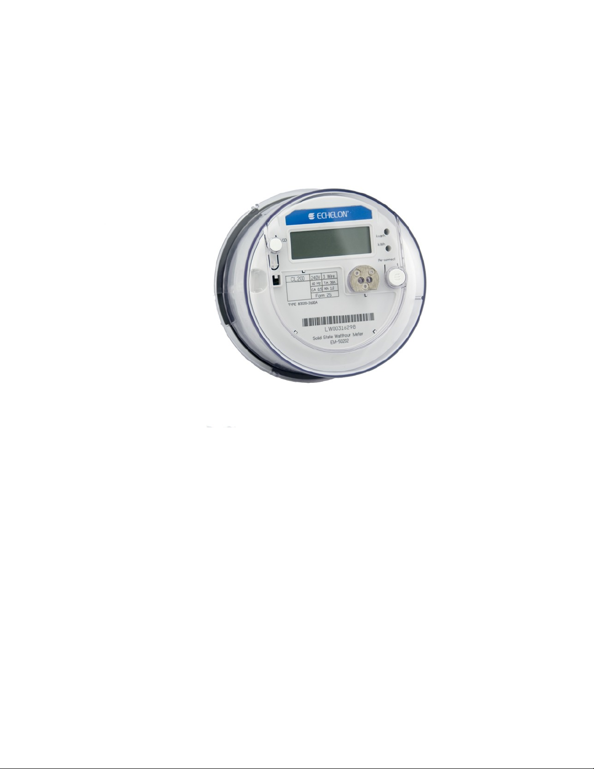
Figure 1.1: Echelon ANSI Electric Meter
4 Introduction
Page 11

2
Meter Installation
This chapter includes safety warnings, meter installation
instructions, and initial start-up procedures.
ANSI Electric Meter v3.1 User’s Guide 5
Page 12
Safety Warnings
Before you install and operate your meters, you should be familiar with all regulatory
agency, manufacturer, and utility industry safety precautions. Observe these safety
precautions during all steps of meter installation, operation, and service. Failure to
comply with these precautions, or with specific warnings or instructions elsewhere in this
guide, violates safety standards of design, manufacture, and the intended use of the
meter. Echelon assumes no liability for failure to comply with these requirements.
The information presented in this guide is intended to be an aid to qualified metering
personnel. It does not replace the extensive training necessary to handle metering
equipment in a safe manner.
!
Safety Warning: Any work on or near energized meters or other metering
equipment presents the danger of electrical shock. Only qualified electricians
and metering specialists should be authorized to work with the meters, in
accordance with local utility safety practices, utility requirements, and other
safety precautions as dictated by local code, regulations, or statutes.
Visual Meter Inspection
Before installing the meter, inspect the meter case, display, optical port, and blades to
make sure they are not damaged.
!
Safety Warning: Return damaged meters and components to Echelon; do
not attempt to repair the damage. The meter has no user-serviceable parts.
Any attempt to remove or repair internal parts voids the meter warranty.
Provisioning the Meter
Before a meter can operate correctly in your system, it must be configured with specific
operating parameters. This configuration is called “provisioning” and is performed by
writing programs with preset values into the meter, either from NES System Software
via the Data Concentrator, or directly to the meter optical port from a computer using
the NES Provisioning Tool application. The parameters in the Provisioning Tool
programs are set by administrative staff at the governing utility, and the programs can
be distributed to technicians for meter provisioning operations.
The meter provisioning may be performed by Echelon prior to shipment, at a service
depot before transportation to the meter installation site, or at the installation site.
After a meter is installed, updates to program settings are usually performed by sending
the updated information from NES System Software to the Data Concentrator that is
supervising the meter. The Data Concentrator writes the update to the meter and
confirms the successful implementation back to NES System Software. For more
information on the Data Concentrator, see the DC-1000/SL and DC-1000/SLE Data
Concentrator User’s Guide.
You can also use the Provisioning Tool to view meter data and diagnostic information.
For instructions on provisioning meters, see the NES Provisioning Tool User’s Guide.
6 Meter Installation
Page 13
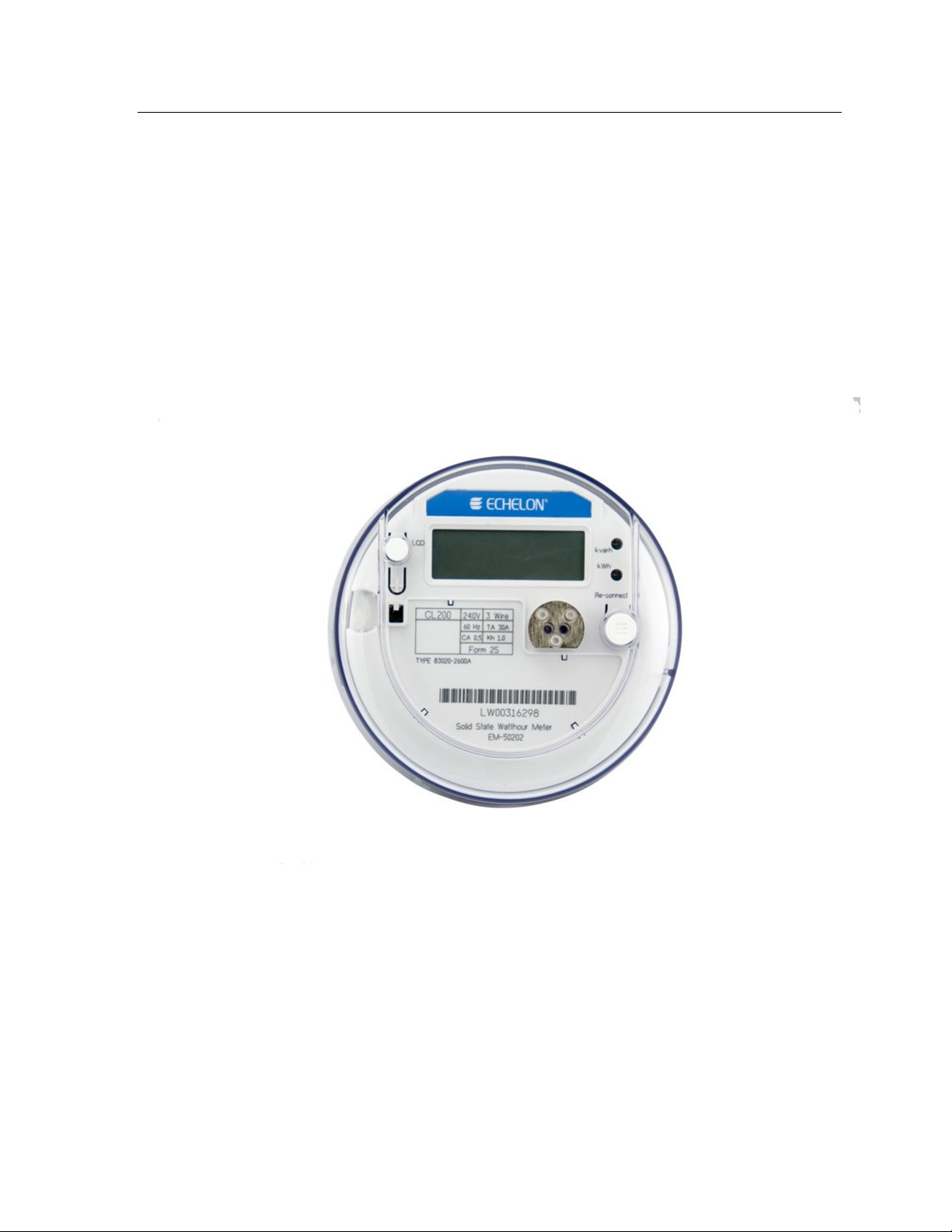
Mounting the Meter
The form, current class and rated voltage of the ANSI meter are marked on the front of
the meter, as shown in Figure 2.1. Before mounting the meter in its socket, you should
make sure that these settings match the form, maximum current and rated voltage for
the socket you are using.
Operating Environment
The meter is designed to operate in an indoor or outdoor (IP54 rating) location, in a nonhazardous environment. You should make sure to mount the meter in a well-ventilated
enclosure that will prevent condensation from forming inside the meter.
Mounting Surface
The meter is designed to be installed in an upright position on a flat vertical surface.
Figure 2.1 Form, Current Class and Rated Voltage
ANSI Electric Meter v3.1 User’s Guide 7
Page 14
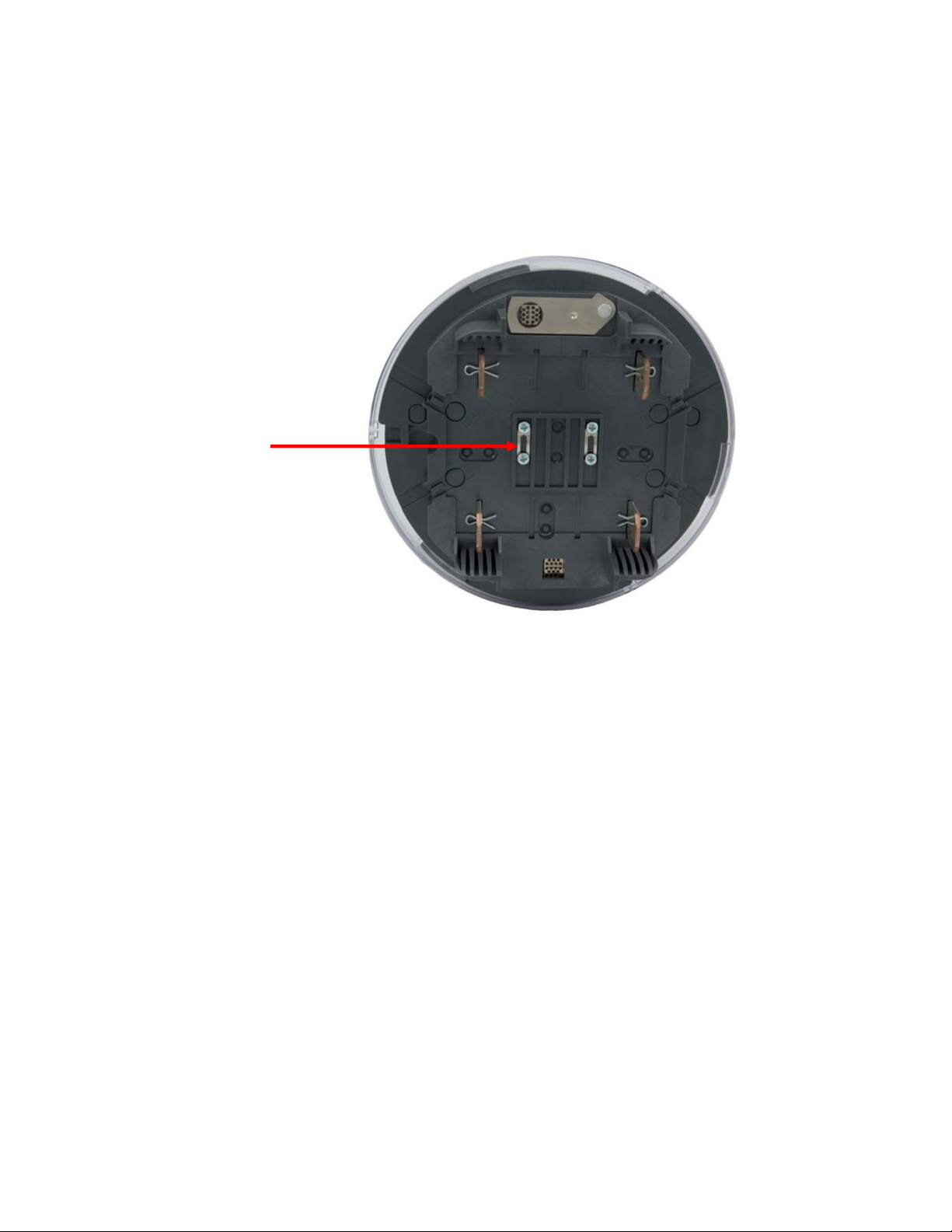
Meter Test Links
The test links of the back of the ANSI meter must be in the closed position before you
mount and begin using the ANSI meter, as shown in Figure 2.2.
Meter Test Links
Figure 2.2 Meter Test Links
8 Meter Installation
Page 15

Determining Load Disconnect and Relay State
without Line Power
The meter’s load disconnect contactor and control relay open or closed state cannot be
visually determined before line power is supplied to the meter. When in the closed state,
power will be delivered to the load when line power is supplied to the meter.
Determining Load Disconnect State
To determine if the meter load disconnect contactor is in the open or closed state when
power is not supplied to the meter, follow this procedure:
1. Set a multi-meter to continuity test mode or use a continuity tester.
2. Connect one continuity test probe to L1 line-in terminal and one probe to L1 load
terminal.
3. If there is NO continuity in the signal path the disconnect is Open (Off). If there
IS continuity in the signal path the disconnect is Closed (On).
Determining Control Relay State
To determine if the control relay is in the open or closed state when power is not
supplied to the meter, follow this procedure:
1. Set a multi-meter to continuity test mode or use a continuity tester.
2. Connect the continuity test probes to the two control relay wires.
3. If there is NO continuity in the signal path the control relay is Open (Off). If
there IS continuity in the signal path the control relay is Closed (On).
ANSI Electric Meter v3.1 User’s Guide 9
Page 16
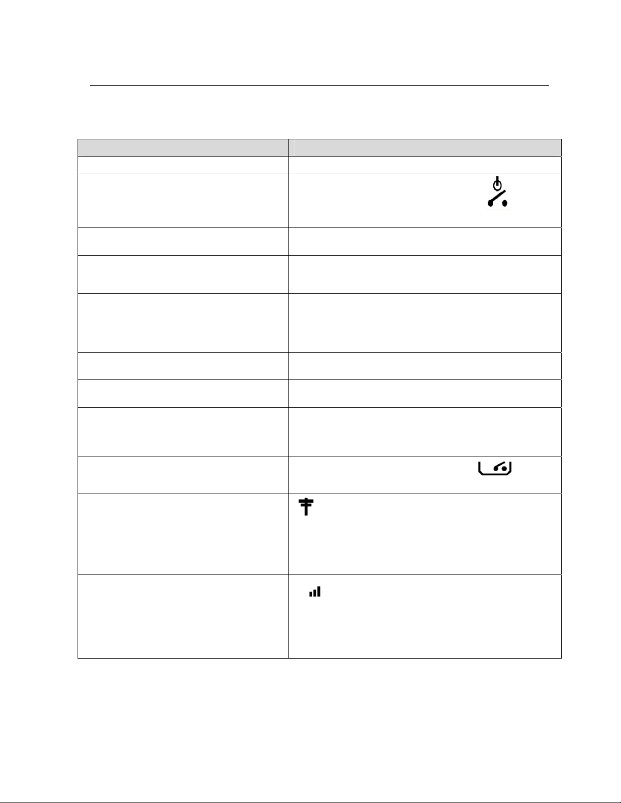
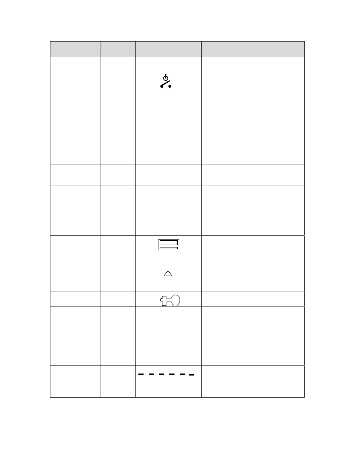
Testing for Correct Meter Operation
When power is applied to the meter, the following can be checked to determine if the
meter is operating properly:
Function/Operation Indicated By
Power to meter is On The display is active (shows information).
Power to load is On
(load disconnect contactor is in the On, or closed,
position)
All necessary phases are connected to the meter
and providing voltage
Polyphase only: The phases are connected to
the meter correctly (Does not detect reversed line
and load wires or swapped line and neutral)
Polyphase only: The phases are not connected
to the meter in the correct order (Does not detect
every possible incorrect connection order such as
L3L1L2, reversed line and load wires, or
swapped line and neutral)
The metered building is consuming active energy
(forward active)
The metered building is generating active energy
(reverse active)
A self-test failed, a tamper condition has been
detected, or an alarm condition has occurred
The main cover has been properly installed and
the cover tamper switch is closed
PLC network communication is occurring
PLC communication has occurred with the meter
(See “Reading the Display” in Chapter 3 for more
information)
The “disconnect open” display indicator
is Not illuminated, indicating that the
disconnect contactor is closed.
The L1 and/or L2 phase indicators are lit on the display,
signifying the phases that have voltage present
L1, L2, L3 (L1, L3 for 2s/12s) indicators are lit on the display
(verification only available for 3-phase, 4-wire electrical service)
L1, L2, L3 (L1, L3 for 2s/12s) indicators are lit on the display
(verification only available for 3-phase, 4-wire electrical service)
The ““ arrow is lit on the display
The ““ arrow is lit on the display
An error code may lock the display or a caution code may be
shown at the end of the scrolling display list, if these codes have
been configured to be active. See “Self Tests and Diagnostic
Messages” on page 1 for information on messages
The “tamper switch open” display indicator
is Not illuminated, indicating that the cover is installed properly
This icon is lit when PLC communication on the network
has been detected by the meter. This icon can be used during
installation to see if network communication can be ‘heard’ by
the meter before the meter is accepted by the system as an
active device. See “Power Line Carrier Communication” on
page 1 for detailed information.
This icon indicates that PLC communication occurred
with this specific meter within the last X minutes (X is
configurable from 1 to 65535 minutes) and shows the quality of
the most recent received PLC message.
See “Power Line Carrier Communication” on page 1 for detailed
information.
10 Meter Installation
Page 17

Test Mode
Test mode is an optional feature that is only supported by some NES version 3.1 ANSI
meters. While in test mode, the meter will suspend standard energy accumulations,
standard demand calculations, power quality analysis, tariff register calculations,
automated control of the disconnect switch, and automated control of the control relay.
In addition, all standard operation demand calculations that were interrupted by test
mode activation will be considered completed and the values will be calculated as if the
full time of the demand interval has elapsed (the non-elapsed time is considered to have
had an energy accumulation of zero). You may find test mode useful if you want to test
the meter’s accuracy without disrupting its billing registers. The meter display includes
an icon that will be enabled when the meter enters test mode.
ANSI Electric Meter v3.1 User’s Guide 11
Page 18

3
Meter Operation
This chapter describes the operation and features of the
Echelon ANSI electric meters.
12 Meter Operation
Page 19
Meter Operation Overview
The Echelon ANSI electric meter provides a comprehensive set of energy services
when operating within the NES system. The meter supplies automatic encrypted
data transfer and diagnostic reporting to NES System Software by communicating
with an Echelon Data Concentrator over local power lines using PLC technology. An
optical port provides local communication for direct programming and data reading.
The meter measures active power and energy for both forward and reverse, reactive
power and energy for import and export, voltage, current, power factor, and
frequency. Data can be recorded in up to 4 perpetual-calendar Time-of-Use (TOU)
registers. The data can be logged in intervals of 5, 15, 30, 60 minutes, or 1-day, with
up to 8 channels per interval.
A programmable display presents comprehensive local information on meter
operation and customer power consumption. Additional messaging features supply
power quality information and tamper detection. LEDs are included for test
functions. An optional KYZ output is also available.
Remote or local disconnect of customer power allows automatic prepay metering
functions, power limiting, and service cancellation control. An optional control relay
can turn an external device on or off based on tariff periods, or by command from
NES System Software or the Provisioning Tool.
NES version 3.1 meters optionally support demand metering, which offer various
types of calculations that can be performed to measure the peak active and reactive
power being delivered to the system over a designated time period. For more
information on demand metering, see Chapter 4, Demand Metering.
NES version 3.1 meters also include a Multipurpose Expansion Port (MEP) that
allows external MEP devices to connect to the meter and access meter data and run
meter procedures. For more information on MEP devices, see Chapter 6, MEP
Devices.
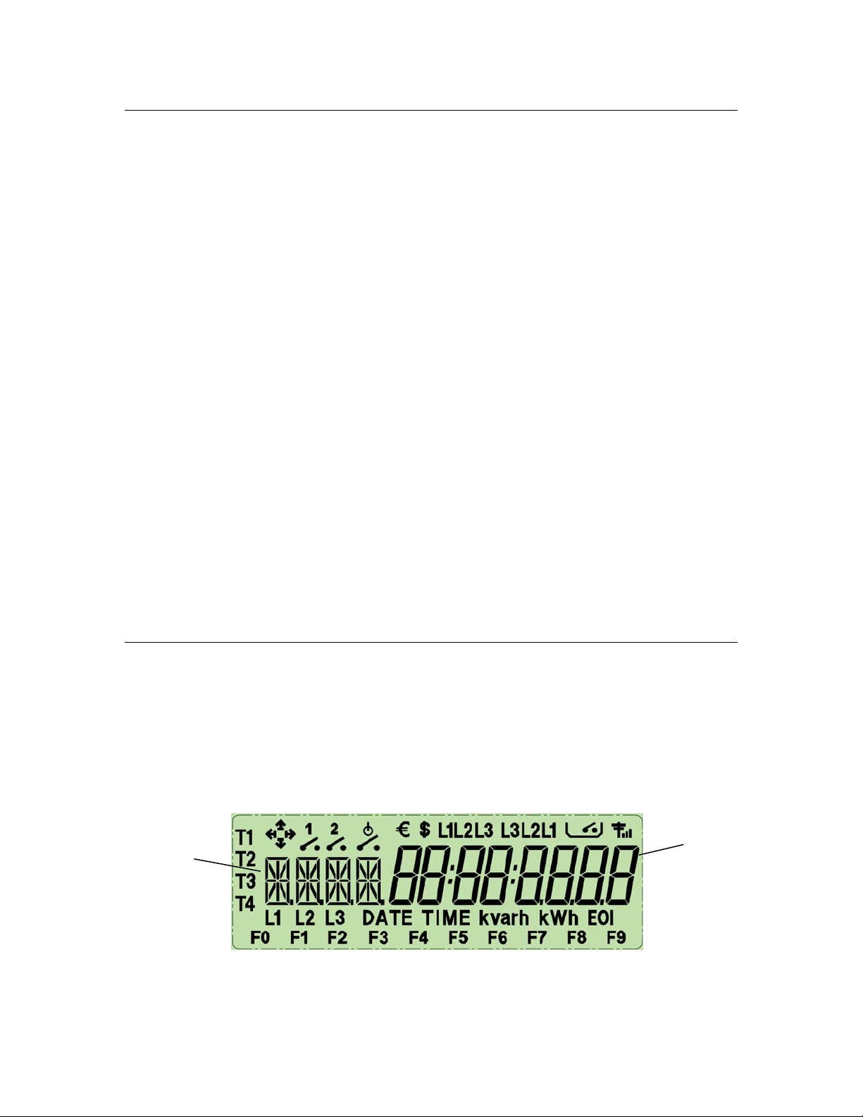
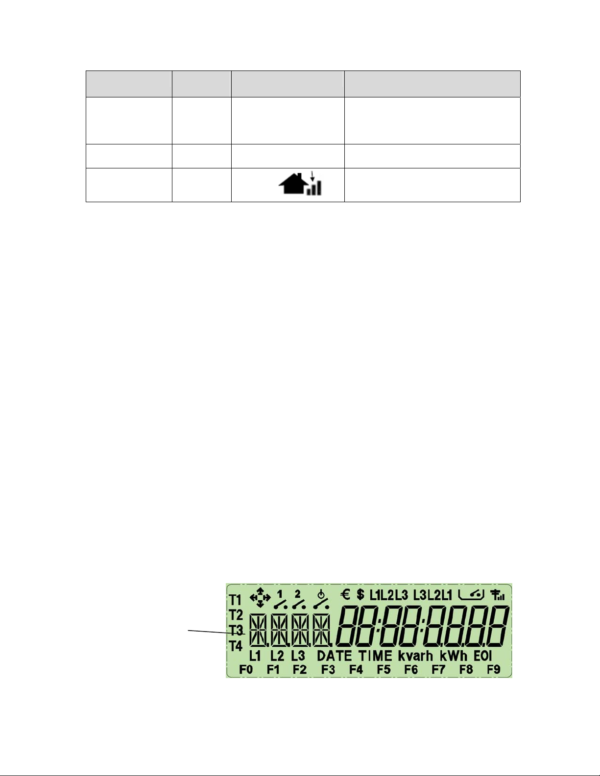
Reading the Display
The indicators on the meter display designate which value is being displayed and
provide indication of various operating parameters. The format of the 8-digit value is
configurable as to the number of digits, viewing of leading zeros, and the decimal
point location. See the NES Provisioning Tool User’s Guide for information on
configuring display options. Refer to Figure 3.1 and the following table for a
description of the display features:
Value ID
code, 4
characters.
Value,
8 digits.
Figure 3.1: Meter Display, All Segments Lit
ANSI Electric Meter v3.1 User’s Guide 13
Page 20
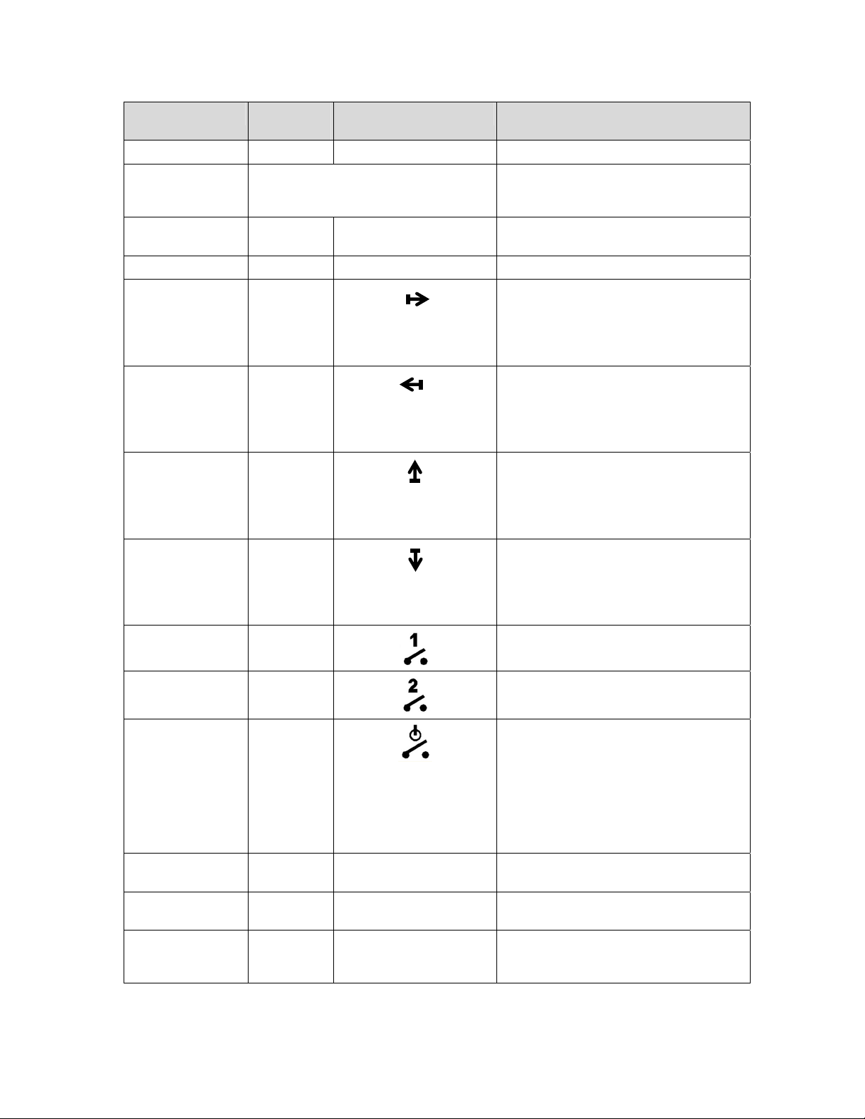
Item Displayed Value
Format
All segments lit All Confirms proper operation of the display.
Value ID code Any letter or number
x.x.x.x.
Value xxxxx.x.x.x Number value. Maximum of 8 numbers and
Present tariff period
Forward active
energy
Reverse active
energy
Import reactive
energy
Export reactive
energy
Control relay 1 open
Control relay 2 open
Indicator Function
Identification code for present displayed
value. Maximum of 4 characters, letters or
numbers.
decimal point of 3 possible places.
T1, T2, T3, T4
Indicates the present operating tariff period.
Indicates that forward active energy is
flowing.
This is also displayed if there is no present
active energy flow and the previous flow
was in the forward direction.
Indicates that reverse active energy is
flowing.
This is also displayed if there is no present
active energy flow and the previous flow
was in the reverse direction.
Indicates that import reactive energy is
flowing.
This is also displayed if there is no present
reactive energy flow and the previous flow
was in the import direction.
Indicates that export reactive energy is
flowing.
This is also displayed if there is no present
reactive energy flow and the previous flow
was in the export direction.
Indicates that control relay 1 is in the open
position.
Not used.
Load disconnect
open
Dollar value xxxxx.x.x.x
Euro value xxxxx.x.x.x
Correct 3-phase
wiring
$
€
L1L2L3
This display indicator can be configured by
the user to either reflect the current state of
the load disconnect contactor, or to indicate
whether or not load side voltage has been
detected by the meter.
For more information on this, see “Display
Indicator for Disconnect Position and Load
Side Voltage” on page 1.
(Not used) Currency value of prepay credit
remaining is displayed in Dollars.
(Not used) Currency value of prepay credit
remaining is displayed in Euros.
Correct wiring configuration order for all 3
phases. (Does not detect reversed line and
load wires or swapped line and neutral.)
14 Meter Operation
Page 21
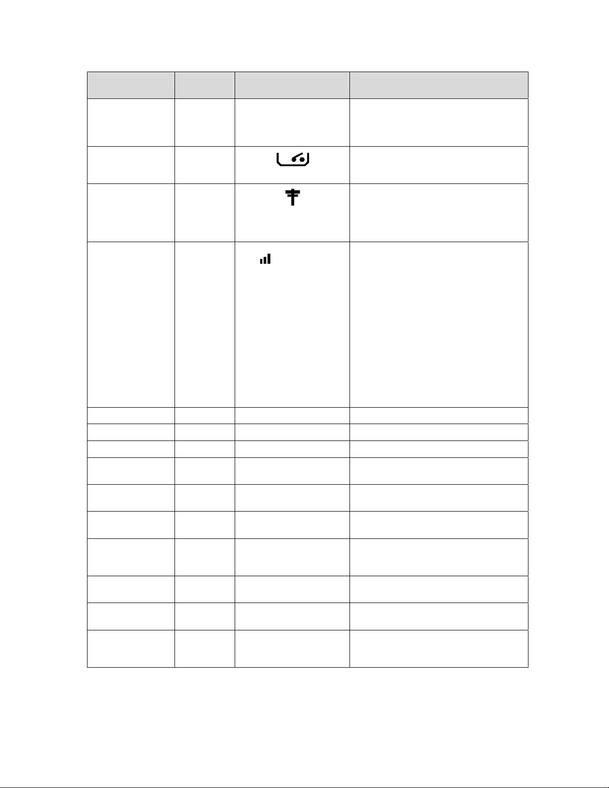
Item Displayed Value
Format
Reverse 3-phase
wiring
Tamper switch open
PLC traffic detection
PLC received
message occurrence
and quality
Line 1 voltage
Line 2 voltage
Line 3 voltage
Meter date dd:mm:20yy
Meter time hh:mm:ss
Reactive energy xxxxx.x.x.x
Active energy xxxxx.x.x.x
Reactive power xxxxx.x.x.x
Active power xxxxx.x.x.x
End of Interval
Indicator Function
L3L2L1
L1
L2
L3
DATE
TIME
kvarh
kWh
kvar
kW
EOI
Indicates that 3-phase wiring is installed in
the wrong order. (Does not detect reversed
line and load wires or swapped line and
neutral.)
Indicates that the main cover tamper switch
is open. The cover is not installed or not
installed correctly.
This icon is lit when PLC communication on
the network has been detected by the
meter. See “Power Line Carrier
Communication” on page 1 for detailed
information.
This icon indicates that PLC
communication occurred with this specific
meter within the last X minutes (X is
configurable from 1 to 65535 minutes) and
shows the quality of the most recent
received PLC message.
– No bars = no message received for this
meter
– Smallest bar = a poor quality message
– Both smallest and medium bar = a
medium quality message
– All three bars = a high quality message
See “Power Line Carrier Communication”
on page 1 for detailed information.
Indicates that voltage is present on line 1.
Indicates that voltage is present on line 2.
Indicates that voltage is present on line 3.
Present local date in meter, or a self-read
record date, is displayed.
Present local DST time in meter, or a self-
read record time, is displayed.
Accumulated import or export reactive
energy is displayed.
Accumulated kilowatt-hours of forward,
reverse, forward + reverse, or forward –
reverse active energy is displayed.
Import or export reactive power is
displayed.
Kilowatts of forward or reverse active power
is displayed.
(Not used) Indicates that a demand reset
has occurred and that a new demand
interval has started.
ANSI Electric Meter v3.1 User’s Guide 15
Page 22
Item Displayed Value
Format
Disconnect status
Nameplate message
active
Load side voltage
detected
Prepay enabled
Self-read/One-time
read error
Access lockout
override in effect
Negative number
indicator
Test mode indicator
Tilt sensor indicator
Simulated
mechanical wheel
Indicator Function
F0, F1, F2
F4
This display indicator, can be configured by
the user to either reflect the current state of
the load disconnect contactor, or to indicate
whether load side voltage has been
detected by the meter.
If it is configured to reflect the current state
of the load disconnect contactor, it will be
illuminated when the load disconnect
contactor is in the open position.
If it configured to indicate whether or not
load side voltage has been detected by the
meter, it will be illuminated when there is no
load side voltage detected by the meter.
For more information on this, see “Display
Indicator for Disconnect Position and Load
Side Voltage” on page 1.
Indicates the nameplate messages that are
presently active in the meter. See additional
description following this table.
Depending on your meter’s
configuration, this icon may be used to
indicate whether or not load side voltage
has been detected by the meter.
For more information on this, see “Display
Indicator for Disconnect Position and Load
Side Voltage” on page 1.
(-)
TEST
TILT
Prepay is enabled in the meter.
Indicates that the current Self-read or
One-time-read record that is being
displayed has errors that may affect
register accuracy.
The access lockout settings are
deactivated by hardware screw.
The number displayed is negative
The meter is in test mode. This icon turns
on when the meter enters test mode, and
turns off when it exits test mode.
The meter includes a sensor that will detect
when the meter has been tilted. This icon
indicates that the sensor has detected a tilt
condition.
The simulated mechanical wheel will scroll
through each of the six indicators at a rate
that indicates the amount of energy
consumed/produced as well as the
direction of energy flow.
16 Meter Operation
Page 23
Item Displayed Value
Format
ANSI meter form
indicator
Name plate
message
MEP communication
indicators
Indicator Function
2S
MP
This icon will be used to display the present
ANSI meter form being used. All ANSI v3.1
meters use form 2S.
Indicates that the MEP device connected to
the meter is registered.
These icons can be configured to flash or
remain on when communication with a
MEP device is occurring.
Error and Caution Display Messages
Various error and caution message codes can be shown on the display. A diagnostic
event can be configured by the user to be shown as either an error or caution
message, or can be set to not appear on the display. The action of each type is:
Caution message codes are shown at the end of the regular scroll list, when a
caution is present. Scrolling continues for all display items.
Error message codes override all regular display items and only the error
message codes are displayed. Scrolling stops for regular display items when
an error is displayed.
Once an error or caution occurs, the display continues to show the error or caution
code until it is cleared. The codes persist across power outages and continue to
display after the meter is powered down and back up. The error or caution codes are
read and cleared by NES System Software via PLC communication with the Data
Concentrator, or directly with the Provisioning Tool via the meter optical port.
All error and caution message codes can be read by the Data Concentrator and sent
to NES System Software, even when not selected to appear on the display.
If more than one error or caution is active, the displayed characters are a
combination of the error or caution values. See “Self Tests and Diagnostic Messages”
on page 1 for a list of the diagnostic messages and an explanation of display codes.
Display Value ID Code
The display value ID code is the user configurable 1 to 4 character alpha/numeric
identifying code for the value currently shown in the 8-digit value field of the meter
display. Different codes are used for power values and error and caution diagnostic
values. See the NES Provisioning Tool User’s Guide for more information on
creating value ID codes. Figure 3.2 shows the 4-character display value ID location.
4-character
value ID code.
Figure 3.2: Display, 4-Character Value ID Code
ANSI Electric Meter v3.1 User’s Guide 17
Page 24

Nameplate Message Identifiers
Various messages may be listed on the front of the meter in the nameplate area.
These messages describe certain states, functions, or actions that could be operating
in the meter. When any of the message states or functions are active in the meter,
the corresponding identifier F0, F1, or F2 is illuminated on the display. The meter
nameplate also includes an erasable strip that can be used to add more data to the
meter display.
Low Voltage Display
During a brownout condition, the meter display will show VOLT LO. This will
continue to be displayed until the meter is powered back up, or until it is completely
powered off. The meter display will also briefly show VOLT LO when the meter is
powered down normally, although the message will not persist in this case.
Display Value Items
The meter can display up to 30 numeric value items, which are chosen from the
available total and tariff energy measurements, as well as time, date, and prepay
energy credit remaining. The display scrolls through each item, with a
programmable scroll-time for each item of 6 to 15 seconds. The scroll-time is the time
that the value is shown on the display before scrolling to the next item. Each item
has a unique programmable 4-character ID code that is displayed along with the
value item.
You can use the meter push button to automatically advance to the next display
value item, before the scroll-time expires. Alternatively, you can disable automatic
scrolling, so that the push button must be used to advance the meter display to the
next item at all times. For more information on the meter push button, see “Push
Button Operation” on page 1.
The decimal point location for energy values is configurable, with an available range
of 1 to 8 digits to the left and 0 to 3 digits to the right of the decimal point. The
display of leading zeros can also be suppressed. The decimal point location and zero
suppression apply only to register values and prepay totals. Other display items,
such as date, time, firmware version, TOU calendar ID, and diagnostic codes are not
affected by the decimal point location and zero suppression settings.
When an actual value is larger than the number of digits configured to the left of the
decimal point, the most significant digits are not displayed. This allows the most
frequently changing digits to display. The actual stored values are not affected.
The following are the choices of items that are available to be shown on the meter
display. The summation and self-read items can be per-tariff or a total of all 4 tariffs,
except for the power outage values, the error counter, which show only totals.
Value Type Item Description
Summation / accumulators Forward active kWh L1+L2+L3
Summation / accumulators Reverse active kWh L1+L2+L3
Summation / accumulators Forward + reverse active kWh L1+L2+L3
Summation / accumulators Forward – reverse active kWh L1+L2+L3
18 Meter Operation
Page 25

Value Type Item Description
Summation / accumulators Import reactive kvarh L1+L2+L3
Summation / accumulators Export reactive kvarh L1+L2+L3
Summation / accumulators Power outage duration minutes (accumulation of all outages since last reset)
Summation / accumulators Power outage count (number of outages since count was last reset to 0)
Summation / accumulators Error Counter - A count of the number of alarms that have occurred for RAM
Failure, Non-Volatile Memory Failure, Clock Error, Measurement Error,
Cover Removed, and Save-All Aborted.
Present / instantaneous Forward active kW L1+L2+L3
Present / instantaneous Reverse active kW L1+L2+L3
Present / instantaneous Import reactive kvar L1+L2+L3
Present / instantaneous Export reactive kvar L1+L2+L3
Present / instantaneous RMS current L1
Present / instantaneous RMS current L2
Present / instantaneous RMS current L3
Present / instantaneous RMS voltage L1
Present / instantaneous RMS voltage L2
Present / instantaneous RMS voltage L3
Present / instantaneous Power factor L1
Present / instantaneous Power factor L2
Present / instantaneous Power factor L3
Present / instantaneous VA power L1+L2+L3
Present / instantaneous Frequency
Present / instantaneous Sine of phase angle L1 (angle between voltage and current on L1)
Present / instantaneous Sine of phase angle L2 (angle between voltage and current on L2)
Present / instantaneous Sine of phase angle L3 (angle between voltage and current on L3)
Demand Date/time
Demand Previous demand value
Demand Present demand value
Demand Cumulative demand value
Demand Continuous cumulative demand value
Demand Maximum demand value
Note: The demand values listed above are available to be displayed for any of the 8 configurable demand
sources. The 8 demand sources are forward power, reverse power, forward + reverse power, and forward
- reverse active power, as well as for reactive power for all 4 quadrants.
Self-read/One-time-read/
Historical demand reset
Self-read/One-time-read/
Historical demand reset
Self-read/One-time-read/
Historical demand reset
Forward active kWh L1+L2+L3
Reverse active kWh L1+L2+L3
Forward + reverse active kWh L1+L2+L3
ANSI Electric Meter v3.1 User’s Guide 19
Page 26

Value Type Item Description
Self-read/One-time-read/
Historical demand reset
Self-read/One-time-read/
Historical demand reset
Self-read/One-time-read/
Historical demand reset
Self-read/One-time-read/
Historical demand reset
Self-read/One-time-read/
Historical demand reset
Self-read/One-time-read/
Historical demand reset
Self-read/Historical
demand reset date and
time
Note: Self-read and One-time-read values can be configured to display from any of the 24 Self-read or
One-time-read data sets stored in the meter, and for 12 of the historical demand reset data stored in the
meter.
Date Local DST (Daylight Saving Time) date in meter
Time Local DST (Daylight Saving Time) time in meter
Pre-pay, total Prepay credit remaining, in Wh
Pre-pay, emergency Prepay emergency credit remaining, in Wh
TOU calendar ID Identifier of the Time-of-Use calendar that is presently operating
Firmware version Firmware version currently running in the meter. You can configure the
Disconnect Open The meter can be configured to display the reason the load disconnect
Demand Resets The number of demand resets that have occurred.
Load Side Voltage
Detected
Forward – reverse active kWh L1+L2+L3
Import reactive kvarh L1+L2+L3
Export reactive kvarh L1+L2+L3
Power outage duration seconds (accumulation of all outages since last
reset)
Power outage count (number of outages since count was last reset to 0)
Error Counter – A count of the number of alarms that have occurred for RAM
Failure, Non-Volatile Memory Failure, Clock Error, Measurement Error,
Cover Removed, and Save-All Aborted.
Date and time that a self-read occurred
meter to display its firmware version for 1-15 seconds on power-up, if
desired.
When the firmware version is shown on the meter display, the alphabet
character portion is shown as a numeric value. The letter “a” is shown as
01, “b” as 02, “c” as 03, and so on through the alphabet. For example,
firmware version 1.00a is shown on the meter display as 01 00 01.
contactor has been opened as a user-specified text string. The follo wing
characters are not supported: K, M, Q, V, W, X.
Note that the digit “2” is used to represent the letter “Z,” the digit “1” is used to
represent the letter “I” and the digit “5” is used to represent the letter “S.”
The meter can be configured to automatically reject remote closing of the
load disconnect contactor when load side voltage is present, and to display
the reason for this as a user-specified text string. The same character
restrictions as described for the Disconnect Open display item above apply.
For more information on this feature, see “Remote Disconnect” on page 1.
Push Button Operation
The push button on the front of the meter (next to the display and labeled LCD),
performs various functions. The button functions are:
20 Meter Operation
Page 27

Display Advance: When pushed and released in less than 3 seconds, the
display immediately advances to the next item. After a change to a new item
due to the activation of the push button, the display shows the item until
either the button is pushed again or the regular scroll time (on time) expires,
whichever occurs first. Once the regular scroll time expires, the display
returns to its normal operation.
Prepay Credit Alarm Silencing: When the audible prepay credit alarm is
activated (due to a low or exhausted prepay credit level) the button can be
pushed for any length of time to silence the alarm.
Push Button Hold Time: When the button is pushed and held down for
longer than 3 seconds, the display changes to show the number of seconds
that the button has been held, and the ID code changes to “PTIM.” This
allows you to track how long the button has been held in order to activate a
desired function.
Self Tests and Diagnostic Messages
The meter performs a comprehensive self-test at power-up and periodically performs
additional diagnostics and self-tests, with messages created to indicate the
occurrence of alarm or error conditions. Some self-tests are performed every second,
minute, hour, daily, or weekly, and some self-tests are performed on power-up only.
Detected faults can be read by the Data Concentrator and transmitted to NES
System Software, and can also be read directly from the meter via the optical port
using the Provisioning Tool. Diagnostic or alarm flags are set for the specific
condition and must be cleared either via the optical port (using the Provisioning Tool)
or by NES System Software through the Data Concentrator. You can configure the
meter to show selected message codes on the display as cautions or errors.
Understanding Display Diagnostic Codes
The diagnostic codes are hexadecimal values, which will allow all possible diagnostic
events to be shown on the display simultaneously. If more than one error or caution is
occurring, the displayed characters are a combination of the error or caution values.
Diagnostic Event Descriptions
The following table lists the diagnostic events that can generate error or caution
messages. The Display Code column shows the value for each event, and is the value
shown on the meter display when only one event in each digit position is being
reported. When more than one event is being reported for the same digit position, the
displayed value is the sum of the event codes. Message codes are displayed on 2
screens, with scrolling between them occurring at the standard scroll time set for the
normal display sequence.
Error or Caution
Item
Display
Code
Description Self-Test
Schedule
Screen 1
Configuration Error 00000002 PLC communications IC initialization failed At power-up
System Reset 00000004 Watch-dog reset or event buffer overflow occurred. May
ANSI Electric Meter v3.1 User’s Guide 21
Display Code Digit Position 8
be due to momentary voltage interruption.
Upon
occurrence
Page 28

r
Error or Caution
Item
RAM Failure 00000008 Memory corruption occurred. Upon
ROM Failure 00000010 Invalid CRC in Bootrom
Non-Volatile
Memory Failure
Clock Error 00000040 Loss of clock memory data or clock functions have been
Measurement Error 00000080 Metering error occurred. Once per
Low Battery 00000100 Real Time Clock backup battery is below 2.5V. Daily
Power Failure 00000800 Power failure occurred since this flag was last cleared.
Display
Code
Display Code Digit Position 7
00000020 CRC verification failed. Memor y may have been
Display Code Digit Position 6
Display Code Digit Position 5
Description Self-Test
corrupted.
suspended due to meter having been without AC power
for an extended period of time.
Detected upon occurrence at time of power-down.
Schedule
occurrence
At power-up
At power-up
second
Upon
occurrence
Cover Removed 00001000 The meter main cover has been removed. Considered a
tamper event.
Reverse Energy 00002000 Meter has registered reverse power for 10 consecutive
seconds. Considered a possible tamper event.
Data Backup
Incomplete
Disconnect Switch
Error
Load Profile
Overflow
Self-Read Occurred 02000000 New self-read has be en recorded. Diagnostic event
Load Disconnect
Open
00004000 A data backup procedure did not complete. At power-up
00008000 Disconnect open/closed state may be incorrect.
Note: This flag is also set when the voltage isolation link is
removed for accuracy testing.
Display Code Digit Position 2
01000000 Load profile memory overflow occurred; unread records
have been overwritten.
coincides with self-read schedule.
04000000 Disconnect switch has been o pened (turned off) by meter
internal command.
Once per
second
Once per
second
Upon
occurrence
Every loadprofile interval
At self-read
Upon
occurrence
and every hou
while off
command is
active
22 Meter Operation
Page 29

Error or Caution
Item
Control Relay Open 08000000 Control relay is in open state. Upon
Phase Loss 10000000 Phase loss detected. By default, this indicates that voltage
Phase Inversion 20000000 Phase inversion detected. Neutral and one phase have
PLC Config Failure 40000000 Error reading PLC configuration data. Data may be
General Error 80000000 Power-down process error and/or display read-back failed. Upon
Display
Code
Display Code Digit Position 1
Display Code Digit Position 8
Description Self-Test
below 61% of rated voltage has been detected on at least
one phase. However, the percentage that constitutes a
phase loss is user-configurable. Considered a possible
tamper event.
been swapped. Considered a possible tamper event.
corrupted.
Screen 2
Schedule
occurrence
and every hour
while relay is
open
Upon
occurrence
Upon
occurrence
At power-up
occurrence
Invalid Password 00000001 An invalid password was entered during optical
communications.
Remote
Communications
Inactive
Current on Missing
or Unused Phase
Reserved 00000008 N/A N/A
Reserved 00000010 N/A N/A
Software CRC Error 00000020 Image ID or CRC error during boot-up procedure. Upon
Code Bank
Changed
Load Profile Backfill
Failed
MEP Installed or
Removed
00000002 Remote communications (PLC) inactiv e for the last 24
hours, by default. The duration required to trigger this
alarm is now user-configurable.
00000004 Current flow greater than 2A detected on a phase with low
or no voltage. This usually indicates that a Potential Test
Link is open. Considered a possible tamper event.
Display Code Digit Position 7
00000040 Active (executing) code bank has been ch anged. Upon
00000080 Load profile was not backfilled at power-up because meter
was off across midnight.
Display Code Digit Position 6
00000100 Indicates that a MEP (Multipurpose Expansion Port)
module has been field installed or removed from the
electric meter.
Upon
occurrence
Daily
Upon
occurrence
occurrence
occurrence
Upon
occurrence
Upon
occurrence
ANSI Electric Meter v3.1 User’s Guide 23
Page 30

Error or Caution
Item
MEP Alarm 00000200 A MEP alarm has occurred. Upon
Reserved 00000400 N/A N/A
Phase Rotation
Changed
Prepay Credit
Exhausted
Prepay Warning
Acknowledged
Event Log Overflow 00004000 The event log is within 10% of using its total capacity. Upon
Mfg Log Entry
Available
Log Dimension
Changed
Display
Code
00000800 Wiring positions for a 3-phase meter have changed, or any
Display Code Digit Position 5
00001000 Prepay credit has gone to 0 (zero). Upon
00002000 User has pushed the button on the front of the meter to
00008000 A meter One-time-read or M-Bus One-time-read has
Display Code Digit Position 4
00010000 The size of one or more logs has chang ed, possibly
Description Self-Test
Schedule
occurrence
Once per
of the phases are inactive or missing.
turn off the audible prepay low credit alarm.
occurred.
impacting how the data is read. For internal use only.
second
occurrence
Upon
occurrence
occurrence
Upon
occurrence
Upon
occurrence.
Not used 00020000
Access Lockout
Override
Power Quality
Event Detected
Event Log Unread
Entries
THD Event
Detected
Unread Entries
Exist in Load Profile
00040000 The access lockout has been deactivated. The access
lockout settings were not, or are not, in effect.
00080000 A power quality event (sag/su rge/over-current) has been
detected on one or more phases.
Display Code Digit Position 3
00100000 One or more unread entries exist in the event log. This
alarm is cleared automatically when there are 0 unread
entries.
00200000 A THD (total harmonic distortion) event has occurred. Upon
00400000 Unread entries exist i n the load profile log. Upon
Reading Diagnostic Code Combinations
The diagnostic codes are assigned a display digit position, with up to 4 items
assigned to each position. When more than one diagnostic event is being reported for
the same digit position, the displayed value is the sum of all event codes. When the
Upon
occurrence
When any new
event is
detected on
any phase, or
when any
event is
removed from
any phase.
Upon
occurrence
occurrence
occurrence
24 Meter Operation
Page 31

added value of the code digits exceeds 9, it will be represented by a hexadecimal
letter. The following table shows the numeric equivalent of the hexadecimal letter.
Hexadecimal Character
Shown on Display
A 10
B 11
C 12
D 13
E 14
F 15
Numeric
Value
Figure 3.3 shows the reference numbering of the display digit positions, and the 4character value ID location.
Diagnostic code display digit position: 1 2 3 4 5 6 7 8
4-character
value ID.
Figure 3.3: Display, All Segments Lit. Diagnostic Code Display Character Locations
Diagnostic Code Interpretation Examples
The display shows on screen 1: 0E001000
For this example, “E” is in Display Code Digit Position 2. E = a numeric value of
14. The following diagnostic events are indicated since their display code sum is
14: “Self-Read Occurred, Disconnect Switch Open, and Control Relay Open.”
“1” is in Display Code Digit Position 5. The following diagnostic event is
indicated: “Cover Removed.”
The display shows on screen 2:
For this example, “1” is in Display Code Digit Position 6. The following diagnostic
event is indicated since its display code sum is 1: “Low Battery.”
“8” is in Display Code Digit Position 7. The following diagnostic event is indicated
since its display code sum is 8: “LP Fill Error.”
00000180
ANSI Electric Meter v3.1 User’s Guide 25
Page 32

r
Display
Characte
1
2
3
4
5
6
7
8
9
A
(=10)
B
(=11)
Look-Up Table for Code Combinations
The following look-up tables show the diagnostic events indicated for all possible
display characters in each digit position for screen 1 and screen 2.
Codes for screen 1:
Digit Position – Screen 1
1 2 3
(not used) 4 (not used)
Phase
Loss
Phase Inv. Self-Read Rev. Energy NV Mem
Phase
Loss
Phase Inv. Self-Read Rev. Energy
PLC Fail Disconnect
Phase
Loss
PLC Fail Disconnect
Phase Inv. Self-Read Rev. Energy NV Mem
PLC Fail Disconnect
Phase Loss LP Overflow Cover Off ROM
Phase Inv. Self-Read Rev. Energy NV Mem
PLC Fail Disconnect
General
Error
Phase
Loss
General
Error
Phase Inv. Self-Read Rev. Energy NV Mem
General
Error
Phase
Loss
Phase Inv. Self-Read Rev. Energy
LP Overflow Cover Off Low Battery ROM
LP Overflow Cover Off ROM
Backup
Open
LP Overflow Cover Off ROM
Backup
Open
Backup
Open
Backup
Open
Relay Open Disconnect
LP Overflow Cover Off Low Battery ROM
Relay Open Disconnect
Relay Open Disconnect
LP Overflow Cover Off ROM
5 6 7 8
Failure
Fail
Failure
NV Mem
Fail
Clock Error System
Incomplete
Failure
Clock Error
Incomplete
Fail
Clock Error System
Incomplete
Failure
Fail
Clock Error
Incomplete
Power Fail Meas. Error RAM Failure
Switch Error
Failure
Power Fail Meas. Error
Switch Error
Fail
Meas. Error RAM Failure
Switch Error
Failure
NV Mem
Fail
Config Error
Reset
Config Error
Reset
Config Error
26 Meter Operation
Page 33

r
ter
Display
Characte
C
(=12)
1 2 3
General
Error
PLC Fail Disconnect
General
Error
Relay Open Disconnect
Open
Relay Open Disconnect
Digit Position – Screen 1
5 6 7 8
(not used) 4 (not used)
Switch Error
Backup
Incomplete
Switch Error
Meas. Error
Clock Error System
Reset
Meas. Error RAM Failure
D
(=13)
E
(=14)
F
(=15)
Phase
Loss
PLC Fail Disconnect
General
Error
Phase Inv. Self-Read Rev. Energy NV Mem
PLC Fail Disconnect
General
Error
Phase
Loss
Phase Inv. Self-Read Rev. Energy NV Mem
PLC Fail Disconnect
General
Error
LP Overflow Cover Off ROM
Backup
Open
Relay Open Disconnect
Backup
Open
Relay Open Disconnect
LP Overflow Cover Off ROM
Backup
Open
Relay Open Disconnect
Incomplete
Switch Error
Incomplete
Switch Error
Incomplete
Switch Error
Failure
Clock Error
Meas. Error
Fail
Clock Error System
Meas. Error RAM Failure
Failure
Fail
Clock Error
Meas. Error
Config Error
Reset
Codes for screen 2:
Digit Position – Screen 2
Display
Charac-
1
2
3
ANSI Electric Meter v3.1 User’s Guide 27
1
(not used) 2 (not used) 3 (not used) 4 (not used)
Event Log
Unread
Entries
THD Event
Detected
Event Log
Unread
Entries
THD Event
Detected
Dimension
Change
Not Used Prepay
Dimension
Change
Not Used Prepay
5 6 7 8
Prepay
Exhausted
Warn Ack
Prepay
Exhausted
Warn Ack
MEP Install
/ Remove
N/A SW CRC
MEP Install
/ Remove
N/A SW CRC
N/A Bad PW
Error
N/A Bad PW
Error
No Comm
No Comm
Page 34

ter
Display
Charac-
4
5
6
7
8
9
A
(=10)
B
(=11)
Digit Position – Screen 2
1
(not used) 2 (not used) 3 (not used) 4 (not used)
Unread
Entries Exist
in Load
Profile
Event Log
Unread
Entries
Unread
Entries Exist
in Load
Profile
THD Event
Detected
Unread
Entries Exist
in Load
Profile
Event Log
Unread
Entries
THD Event
Detected
Unread
Entries Exist
In Load
Profile
Power
Dimension
Power
Not Used Prepay
Power
Dimension
Not Used Prepay
Access
Lockout
Override
Dimension
Change
Access
Lockout
Override
Not Used Prepay
Acces
Lockout
Override
Dimension
Change
Not Used Prepay
Acces
Lockout
Override
Quality
Event
Detected
Change
Quality
Event
Detected
Quality
Event
Detected
Change
5 6 7 8
Event Log
Overflow
Prepay
Exhausted
Event Log
Overflow
Warn Ack
Event Log
Overflow
Prepay
Exhausted
Warn Ack
Event Log
Overflow
Mfg Log
Entry
Available
Prepay
Exhausted
Mfg Log
Entry
Available
Warn Ack
Mfg Log
Entry
Available
Prepay
Exhausted
Warn Ack
N/A Code Bank
MEP Install
/ Remove
N/A Code Bank
N/A SW CRC
N/A Code Bank
MEP Install
/ Remove
N/A SW CRC
N/A Code Bank
Phase
Changed
MEP Install
/ Remove
Phase
Changed
N/A SW CRC
Phase
Changed
MEP Install
/ Remove
N/A SW CRC
0 V Current
Changed
N/A Bad PW
0 V Current
Changed
No Comm
Error
0 V Current
Changed
N/A Bad PW
No Comm
Error
0 V Current
Changed
LP Fill Error N/A
N/A Bad PW
LP Fill Error N/A
No Comm
Error
LP Fill Error N/A
N/A Bad PW
No Comm
Error
28 Meter Operation
Page 35

ter
Display
Charac-
C
(=12)
D
(=13)
E
(=14)
F
(=15)
Digit Position – Screen 2
1
(not used) 2 (not used) 3 (not used) 4 (not used)
Power
Quality
Event
Detected
Access
Lockout
Override
Power
Quality
Event
Detected
Dimension
Change
Access
Lockout
Override
Power
Quality
Event
Detected
Not Used Prepay
Access
Lockout
Override
Power
Quality
Event
Detected
Dimesnion
Change
Not Used Prepay
Access
Lockout
Override
Power
Quality
Event
Detected
5 6 7 8
Mfg Log
Entry
Available
Event Log
Overflow
Mfg Log
Entry
Available
Prepay
Exhausted
Event Log
Overflow
Mfg Log
Entry
Available
Warn Ack
Event Log
Overflow
Mfg Log
Entry
Available
Prepay
Exhausted
Warn Ack
Event Log
Overflow
Mfg Log
Entry
Available
Phase
Changed
N/A Code Bank
Phase
Changed
MEP Install
/ Remove
N/A Code Bank
Phase
Changed
N/A SW CRC
N/A Code Bank
Phase
Changed
MEP Install
/ Remove
N/A SW CRC
N/A Code Bank
Phase
Changed
LP Fill Error N/A
0 V Current
Changed
LP Fill Error N/A
N/A Bad PW
0 V Current
Changed
LP Fill Error N/A
No Comm
Error
0 V Current
Changed
LP Fill Error N/A
N/A Bad PW
No Comm
Error
0 V Current
Changed
LP Fill Error N/A
Power Quality
The meter monitors various parameters for power quality. Power quality events can
be read by the Data Concentrator and transmitted to NES System Software, and can
also be read directly from the meter via the optical port. When a power quality event
ANSI Electric Meter v3.1 User’s Guide 29
Page 36

occurs, the status must return to normal for at least 1 second for another power quality
event to be recorded. The meter provides power quality measurements for:
Voltage (RMS) sag (under voltage): Records the number of voltage sag
occurrences on any one phase. A voltage sag must last continuously for the
time set in the meter Sag/Swell Duration Threshold to be recorded as an
event. The threshold that determines if a voltage sag is recorded, is
configurable as a percentage below the factory-rated voltage. The threshold
range is 1 to 99%. The lowest voltage that occurred during the most recent
sag (after the duration threshold is met) is recorded, as well as the date and
time that the lowest recorded voltage occurred.
The user-configurable Sag/Swell Duration Threshold sets the number of
minutes that a voltage sag or swell must be sustained to be recorded as an
event. A setting of 0 (zero) forces the recording of every detected event. The
range is 0 to 255 minutes.
Voltage (RMS) swell (over voltage): Records the number of voltage swell
occurrences on any one phase. A voltage swell must last continuously for the
time set in the meter Sag/Swell Duration Threshold to be recorded as an
event. The threshold that determines if a voltage swell is recorded is
configurable as a percentage above the factory-rated voltage. The threshold
range is 1 to 99%. The highest voltage that occurred during the most recent
swell (after the duration threshold is met) is recorded, as well as the date and
time that the highest recorded voltage occurred.
Over-current (RMS): Records the number of over-current events on any one
phase. The over-current condition must last continuously for 10 seconds to be
recorded as an event. The threshold that determines if an over-current condition
is recorded is configurable as a percentage above the maximum current (as
labeled on the meter cover) on any one phase.
Power outages: Records the duration, power on date and time, and power off
date/time of the last 10 long power outages. Records a count of all short power
outages. The voltage must be below the internal power outage level and last
longer than the time (in seconds) set in the user-configurable Power Outage
Duration Threshold to be recorded as a long power outage event. The internal
power outage level is permanently set to approximately 74% of the rated voltage.
The range of the Power Outage Time Threshold is 0 to 65,535 seconds. Power
outages that are shorter than the Power Outage Time Threshold, but at least
200 milliseconds (approximately), are counted as a short power outage. If the
Power Outage Duration Threshold is set to 0 (zero) the duration and date/time of
every power outage event longer than approximately 200 milliseconds is
recorded, with complete records for the last 10 long outages. In this case, the
short outage count is not incremented.
Frequency: The frequency is constantly monitored (except for the first 1 to 2
seconds after power-up) and the maximum and minimum values, since last
reset, are recorded along with the time of the event.
Phase loss: Records the number of phase loss occurrences on any one phase
as well as the date and time of the last occurrence. Voltage (RMS) drop on
any phase below the internal phase loss level for a sustained duration of 10
seconds is considered a phase loss. The internal phase loss level is set to
approximately 61% of the rated voltage by default, although this figure is
user-configurable as of version 3.1. Since this event can affect the accuracy of
the meter, energy accumulation is automatically reconfigured to exclude the
lost phase. A phase loss error message can be shown on the display if
30 Meter Operation
Page 37

configured by the user. Phase loss also causes a diagnostic code to be
activated.
Total harmonic distortion (THD): Records three types of total harmonic
distortion: voltage total harmonic distortion (VTHD), current total harmonic
distortion (ITHD) and VA (volts-amperes) total harmonic distortion
(VATHD). THD is a ratio of the voltage or current at harmonic frequencies to
the voltage or current at the fundamental frequency for the meter, expressed
as a percentage. A THD event occurs when the value of any THD
measurement exceeds the defined threshold for the duration specified for that
threshold. For ANSI meters, THD measurements are made for the system
and not per phase, meaning that if you have different harmonics on separate
phases, the THD value reported by the ANSI meter will be a combination of
those values.
The number of total harmonic distortion events, the date/time of the last
occurrence, the average value of the last occurrence, and the maximum value
of the last occurrence are stored as power quality data, and can be recorded
in the meter event log. A THD event occurs when the value for any THD
measurement goes above the defined threshold for that THD value for the
duration specified for that threshold.
Note: ITHD calculations will be disabled when the current is lower than 200 mA,,
because the current wave form will be distorted under these circumstances and
the ITHD calculation will be invalid. VATHD calculation will also be affected
by this threshold since its calculation is related to ITHD.
Note: THD calculations may be impacted by the meter’s optical or PLC
communications, so the time required to perform each THD calculation may
vary.
THD Calculations
There are two methods of calculating the VTHD and ITHD. The method used is userconfigurable. The first method, shown below, is defined in IEC 61000-4-7.
10
2
N
2
VTHD
2
10
2
N
2
ITHD
The second method used to calculate VTHD and ITHD uses the RMS value to
calculate the THD.
VTHD
2
10
2
N
harmonicorderNthofrmsV
componentlfundamentaofrmsV
harmonicorderNthofrmsI
componentlfundamentaofrmsI
harmonicorderNthofVrms
componentlfundamentaofVrms
ANSI Electric Meter v3.1 User’s Guide 31
Page 38

10
harmonicorderNthofIrms
2
ITHD
N
componentlfundamentaofIrms
The following method is used to calculate VATHD.
10
2
N
VATHD
Event Log
The event log records the occurrence of meter events and fault conditions that are
selected to be logged. The date and time of each event occurrence is included in the
log. Some events include numeric codes to provide more detail about the event, such
as the specific type of action that occurred, a table or procedure number, or the new
season or tariff that took effect. The event log shows a zero (0) when no code value is
available for that event, or if one of the available codes is zero and that is the valid
indication.
*
harmonicorderNthofIrmsharmonicorderNthofVrms
)*(
componentlfundamentaofIrmscomponentlfundamentaofVrms
The event log stores up to 100 of the most recent events. When the event log is full,
the oldest events are over-written.
Status Events
The following are status events that can be selected for inclusion in the event log.
Status Name Description Event ID Descriptor
Primary Power
Down
Primary Power
Up
Time Changed
(old time)
Power off date and time.
Note: Power Up and Power Down
events are only logged after the Power
Outage Duration Threshold time has
elapsed.
Power on date and time. This event is
triggered upon power restoration and
also the other reset causes listed in the
Codes column.
The previous date and time in effect
when the time was changed.
1
2 3 = Power failure
4 = Watchdog reset
5 = Code Bank Switchover event
8 = Brown-out
11 = Bootrom Switchover
Other codes are for Echelon internal use
3 0 = A specific, absolute new time was written to the
meter.
A time = An amount of gradual time change
requested from the System Software.
See procedures 2064 and 10 in the meter procedure
tables below.
32 Meter Operation
Page 39

Status Name Description Event ID Descriptor
Time Changed
(new time)
Meter Accessed
for Write
Procedure
Invoked
Table Written To Date and time an outside source wrote to
Reset List
Pointers
If procedure 10 (absolute change) is used
for the time change, this event time is the
new time that was set.
If procedure 2064 (gradual change) is
used for the time change, this event time
is the resulting new time after completion
of the gradual change.
Date and time an outside source wrote
data into a meter table or via a meter
procedure into a table.
Date and time an outside source invoked
a specific meter procedure. Enabling this
event allows access to the procedure
folders. Choose those procedures that
are to trigger this event.
a specific meter table. Enabling this
event allows access to the table folders.
Choose those tables that, when written
to, are to trigger this event.
List pointers for load profile, self read or
event log were reset. This changes the
number of unread records to zero.
4
8
9 Procedure number
10 Table number
14 2 = self read
3, 7 = load profile
8 = event log
255 = all of the above
Update List
Pointers
Event Log
Erased
Event Log
Pointers
Changed
Demand Reset
Occurred
Self-Read
Occurred
Daylight Saving
Time On
Daylight Saving
Time Off
List pointers for load profile, self read, or
event log were updated. This changes
the number of unread records.
The event log was erased. 18
Event log pointer position was changed. 19 New value for pointer
A demand reset has occurred. 20
A Self-Read occurred. 21
The meter switched into Daylight Saving
Time.
The meter switched out of Daylight
Saving Time.
15 2 = self read
3, 7 = load profile
8 = event log
255 = all of the above
22
23
ANSI Electric Meter v3.1 User’s Guide 33
Page 40

Status Name Description Event ID Descriptor
Season Change A TOU season change occurred. 24 0 = Season 1
1 = Season 2
2 = Season 3
3 = Season 4
Special Schedule
Activation
Tier Switch
Change
Pending Table
Activation
Pending Table
Clear
Test Mode
Started
Test Mode
Stopped
Meter
Reprogrammed
A day deemed as a TOU holiday. 26 0 = Special schedule A
1 = Special schedule B
The meter switched from one tariff to
another per day table settings or via
procedure (forced tariff change).
The TOU pending table was activated. 28 4119 = Internal system use
The TOU pending table was cleared. 29 4119 = Internal system use
The meter has entered test mode. 30
The meter has exited test mode. 31
New firmware operating code was written
to the meter.
27 0 = Tariff 1
1 = Tariff 2
2 = Tariff 3
3 = Tariff 4
4150 = Preset TOU schedule changeover
4150 = Preset TOU schedule changeover was
cancelled
36 New firmware version number (Echelon-internal
formatting)
34 Meter Operation
Page 41

Status Name Description Event ID Descriptor
Load Disconnect
State Changed
The state of the load disconnect
contactor has changed. This event codes
return indicate the load disconnect
contactor’s current state, as well as the
reason for the change in state.
66 Bits 0..3 indicate the current state:
1 = closed
2 = opened
3 = locked open
Bit 4 indicates whether or not the change in state was
successful:
0 = successful
1 = failure
Bits 5 is reserved for future use.
Bit 6: Previous internal status (MP30 and power-up
resynchronizations only)
0 = open,
1 = closed
Bit 7: Previous external status (MP30 and power-up
resynchronizations only)
0 = open
1 = closed
High byte indicates the reason the state has
changed:
1 = MP02 operation
2 = Maximum Power
3 = Prepay
4 = Prepay Power
5 = MP23 operation
6 = Manual operation
7 = Schedule
8 = MP30 invoked
9 = Disconnect resynchronization occurred
10 = Power-up resynchronization occurred
Control Relay
Open
Invalid Password An invalid password was entered during
Code Bank
Changed
Load Profile
Backfill Failed
MEP AutoDiscovery
Complete
Manufacturer Log
Entry Occurred
Control relay is in open state. 67
72
optical communications.
Active (executing) code bank has been
changed.
Load profile was not backfilled completely
at power-up because meter was off
across midnight.
Indicates that the meter has completed a
MEP auto-discovery process.
An entry has been made in the
manufacturer log.
78
79
82
87
ANSI Electric Meter v3.1 User’s Guide 35
Page 42

Status Name Description Event ID Descriptor
Log Dimension
Changed
Unread Load
Profile Entries
Exist
MEP Status
Changed
The dimensions or semantics of the
meter’s interface have changed.
Unread entries exist in the load profile
log.
Status has changed for a MEP device. 96 0 = Device 0 is commissioned and assigned to
88 0000 = Initial meter load
0002 = Interface compatibility setting changed during
commissioning.
0003 = Interface compatibility changed via a table
write.
0xxx = Procedure invoked causing interface
compatibility change, where xxx is the number of the
procedure invoking the change
94
position 1, 2, 3, or 4
1 = Device 0 commission failed, no available position
2 = Device 0 commission failed, lost communication
4 = Device 0 removed logically from meter
8192 = Device 1 is commissioned
8193 = Device 1 commissioned failed, no available
position
8194 = Device 1 commission failed, lost
communication
8196 = Device 1 removed logically from meter
16384 = Device 2 is commissioned
16385 = Device 2 commission failed, no available
position
16386 = Device 2 commission failed, lost
communication
16388 = Device 2 removed logically from meter
24576 = Device 3 is commissioned
24577 = Device 3 commission failed, no available
position
24578 = Device 3 commission failed, lost
communication
24580 = Device 3 removed logically from meter
32768 = Device 4 is commissioned
32769 = Device 4 commission failed, no available
position
32770 = Device 4 commission failed, lost
communication
32772 = Device 4 removed logically from meter
40960 = Device 5 is commissioned
40961 = Device 5 commission failed, no available
position
40962 = Device 5 commission failed, lost
communication
40964 = Device 5 removed logically from meter
40965 = Device 5 registered ( MEP devices only)
36 Meter Operation
Page 43

Status Name Description Event ID Descriptor
Maximum Power
Level Threshold
Switched
Maximum Value
for Voltage THD
Event
Maximum Value
for Current THD
Event
The maximum power level has changed. 97 0 = Max power level changed from primary to
secondary
1 = Max power level changed from secondary to
primary. The event is not generated if switch
is attempted when meter is already in
primary mode.
Maximum THD (total harmonic distortion)
of the last finished voltage THD event, for
the peroid that VTHD goes beyond or
below the threshold.
Maximum THD of last finished ITHD
event, for the peroid that ITHD goes
beyond or below the threshold.
100 Bits 0-1 of the argument is used to indicate the
phase:
0 = phase A
1 = phase B
2 = phase C
The remaining bits are used for the VTHD value.
You can divide the argument value by 4 to get the
THD value
101 Bits 0-1 of the argument is used to indicate the
phase:
0 = phase A
1 = phase B
2 = phase C
The remaining bits are used for the ITHD value. You
can divide the argument value by 4 to get the THD
value
Maximum Value
for Apparent
Power THD
Event
Average Value
for Voltage THD
Event
Maximum THD of last finished VATHD
event, for the peroid that VATHD goes
beyond or below the threshold.
Average THD of last finished VTHD
event, for the peroid that VTHD goes
beyond or below the threshold
102 Bits 0-1 of the argument is used to indicate the
phase:
0 = phase A
1 = phase B
2 = phase C
The remaining bits are used for the VATHD value.
You can divide the argument value by 4 to get the
THD value
103 Bits 0-1 of the argument is used to indicate the
phase:
0 = phase A
1 = phase B
2 = phase C
The remaining bits are used for the VTHD value.
You can divide the argument value by 4 to get the
THD value
ANSI Electric Meter v3.1 User’s Guide 37
Page 44

Status Name Description Event ID Descriptor
Average Value
for Current THD
Event
Average Value
for Apparent
Power THD
Event
Disconnect
Pulsed
Average THD of last finished THD event,
for the peroid that THD goes beyond or
below the threshold
Average THD of last finished VATHD
event, for the peroid that VATHD goes
beyond or below the threshold.
The meter has pulsed the load
disconnect contactor. This may occur
when the physical state of the load
disconnect contactor does not match the
desired internal state. For more
information on this, see “Load Disconnect
Re-Synchronization” on page 1.
104 Bits 0-1 of the argument is used to indicate the
phase:
0 = phase A
1 = phase B
2 = phase C
The remaining bits are used for the ITHD value. You
can divide the argument value by 4 to get the THD
value
105 Bits 0-1 of the argument is used to indicate the
phase:
0 = phase A
1 = phase B
2 = phase C
The remaining bits are used for the VATHD value.
You can divide the argument value by 4 to get the
THD value.
106
This event is primarily for diagnostic purposes.
High byte nonzero Argument format 1
Bit 0 = desired external state
(0 = open, 1 = closed)
Bit 1 = power down pending
(0 => not pending)
Bit 2..15 = low 16 bits of the program counter of
the calling routine
divided by 4
High byte all 0s Argument format 2
Bits 0..7 = disconnect pulse count
Alarm Events
The following are alarm events that can be selected for inclusion in the event log.
Alarm Name Description Event ID Descriptor
Configuration
Error
System Reset Watch-dog reset or event buffer overflow
38 Meter Operation
Power Line Carrier (PLC)
communications IC initialization failed.
PLC may be non-functional. Urgent
reporting priority is recommended.
occurred. May be due to momentary
voltage interruption. An unexpected
software error has occurred. Urgent
reporting priority is recommended.
37 Echelon internal use
38 0 = Watch-dog timeout
1 = Event buffer overflow, some events may be lost
2 = Abnormal power interrupt
Other codes are for Echelon internal use
Page 45

Alarm Name Description Event ID Descriptor
RAM Failure Memory corruption occurred. 39 1 = LP value corrupted
3 = Disconnect or control relay value corrupted
4 = RAM memory test error
5 = RTC code in NVRAM corrupted
6 = NVRAM alarm variable corrupted
ROM Failure Invalid CRC in Bootrom. 40
Non-Volatile
Memory
Failure
Clock Error Loss of clock memory data or clock
Measurement
Error
Low Battery Real Time Clock (RTC) backup battery is
Cover
Removed / Tilt
Detected
Reverse
Energy
CRC verification failed. Memory may
have been corrupted.
functions have been suspended due to
meter having been without AC power for
an extended period of time.
Metering error occurred.
Note: This event is reported again on
every power-up if the condition
continues.
below 2.5V.
The meter main cover has been
removed, or the meter has detected a tilt
condition. Considered a tamper event.
Note: This event is reported again on
every power-up until the tamper
condition is cleared.
Meter has registered reverse power for
10 consecutive seconds. Considered a
possible tamper event.
41 Table number:
65534 = Bootrom FRAM CRC/signature invalid
65535 = all tables
42 Echelon-internal use
43 Echelon-internal use
44
47 If bit 0 is set to 1, then the cover has been removed.
If bit 3 is set to 1, then a tilt condition has been
detected.
48
Data Backup
Incomplete
A data backup procedure did not
complete. Up to one hour’s worth of
billing and other FRAM data may have
been lost. Urgent reporting priority is
recommended.
49
ANSI Electric Meter v3.1 User’s Guide 39
Page 46

Alarm Name Description Event ID Descriptor
Disconnect
Switch Error
Load Profile
Overflow
Phase Loss Phase loss detected. By default, this
Disconnect open/closed state may be
incorrect. This generally indicates that
the internal state of the load disconnect
contact does not match the acutal
physical state of the load disconnect
contactor.
Depending on your meter’s
configuration, this even may also
incicate that the meter has detected load
side voltage. You can configure the
meter to trigger either this alarm or the
Load Side Voltage Detected alarm when
load side voltage is detected. By default,
the meter will use the Load Side Voltage
Detected alarm, unless your meter was
upgraded to use the v3.1 firmware from
a version that did not include the Load
Side Voltage Detected alarm.
Note: This event is also set when the
voltage isolation link is removed for
accuracy testing.
Load profile memory overflow occurred;
unread records have been overwritten.
indicates that voltage below 61% of
rated voltage has been detected on at
least one phase. However, the
percentage that constitutes a phase loss
is user-configurable. Considered a
possible tamper event.
Note: This event is reported again on
every power-up until the phase has been
recovered.
50 For a complete description of the bits returned with
this event, see “Load Disconnect Re-
Synchronization” on page 1.
64
68 1 = Line 1 Phase Lost (L1)
2 = Line 2 Phase Lost (L2)
3 = L1 & L2
4 = Line 3 Phase Lost (L3)
5 = L1 & L3
6 = L2 & L3
7 = L1 & L2 & L3
Phase
Inversion
PLC Config
Failure
General Error Power-down process error and/or
Remote
Communicatio
ns Inactive
Phase inversion detected. Neutral and
one phase have been swapped.
Considered a possible tamper event.
Error reading PLC configuration data.
Data may be corrupted.
display read-back failed. An unexpected
power-down sequence occurred. Urgent
reporting priority is recommended.
Remote communications (PLC) inactive
for a user-specified length of time. You
can specify the duration required to
trigger this alarm (in minutes), and you
can also disable the alarm completely.
69 2 = Plus 120° Inverted
4 = Plus 180° Inverted
6 = Minus 120° Inverted
70
71 0 = Power-down
1 = Display
73
40 Meter Operation
Page 47

Alarm Name Description Event ID Descriptor
Current on
Missing or
Unused Phase
Software CRC
Error
MEP Installed
or Removed
MEP Alarm A MEP alarm has occurred. 81 The MEP Status event returns a 15-bit argument
Current flow greater than 2A detected on
a phase with low or no voltage. This
usually indicates that a Potential Test
Link is open. Considered a possible
tamper event.
Note: This event is reported again on
every power-up until the condition no
longer exists.
Downloaded firmware update image ID
or CRC error during boot-up procedure.
The code in the downloaded application
may be corrupted. Non-urgent reporting
priority is recommended.
Indicates that a MEP (Multipurpose
Expansion Port) module has been field
installed or removed from the electric
meter.
74 1 = On line 1 (L1)
2 = On line 2 (L2)
3 = L1 & L2
4 = On line 3 (L3)
5 = L1 & L3
6 = L2 & L3
7 = L1 & L2 & L3
77
80 0 = MEP module installed
1 = MEP module removed
indicating which MEP device the event has occurred
on, and what event has occurred. Bits 15..13 identify
the MEP device:
101 = MEP device
Bits 12..0 identify the event that has occurred:
0 = Scheduled billing read completed
1 = Scheduled billing read completed with
application
errors
2 = Status read completed with device alarms
3 = Billing read overflow
4 = Device read failed
5 = Serial number mismatch occurred on billing
read
Phase
Rotation
Changed
Prepay Credit
Exhausted
Prepay
Warning
Acknowledged
Magnetic
Tamper
Wiring positions for a 3-phase meter
have changed, or any of the phases are
inactive or missing.
Prepay credit has gone to 0 (zero). 84
User has pushed the button on the front
of the meter to turn off the audible
prepay low credit alarm.
A magnetic tamper event has been
detected.
83 Present status:
85
89
0 = L1L2L3
1 = L3L2L1
2 = Rotation Unknown
ANSI Electric Meter v3.1 User’s Guide 41
Page 48

Alarm Name Description Event ID Descriptor
Access
Lockout
Override
Power Quality
State Changed
Voltage Sag
The access lockout settings have been
deactivated.
A power quality event (sag/surge/overcurrent) has been detected. Bit mask, bit
value 1 means event detected, value 0
means event cleared.
The lowest voltage of the last finished
sag event. The timestamp indicates
when the lowest voltage was detected.
When a sag event occurs, the fractional
part of the voltage value that caused the
event is removed before it is recorded
into the meter event log. As a result of
this truncation, the voltage values in the
event log that correspond to some sag
events may not appear to exceed the
threshold defined for sag events.
90 0 = Override condition gone
1 = Override detected
91 Bit 0 = phase A sag
Bit 1 = phase B sag
Bit 2 = phase C sag
Bit 3 = phase A surge
Bit 4 = phase B surge
Bit 5 = phase C surge
Bit 6 = phase A over-current
Bit 7 = phase B over-current
Bit 8 = phase C over-current
98 Bits 0-1 of the argument are used to indicate the
phase:
0 = phase A
1 = phase B
2 = phase C
The remaining bits are used for the voltage value in
volts. You can divide the argument value by 4 to get
the voltage value
Voltage Swell
The highest voltage of last finished surge
event. The timestamp of this event
indicates when the highest voltage is
detected.
When a swell event occurs, the fractional
part of the voltage value that caused the
event is removed before it is recorded
into the meter event log. As a result of
this truncation, the voltage values in the
event log that correspond to some swell
events may not appear to exceed the
threshold defined for swell events.
99 Bits 0-1 of the argument are used to indicate the
phase:
0 = phase A
1 = phase B
2 = phase C.
The remaining bits are used for the voltage value, in
volts. You can divide the argument value by 4 to get
the voltage value.
42 Meter Operation
Page 49

Alarm Name Description Event ID Descriptor
Load Side
Voltage
Detected
Depending on your meter’s
configuration, this even may incicate that
the meter has detected load side voltage
when the load disconnect contactor is in
the open state. You can configure the
meter to trigger either this alarm or the
Disconnect Switch Error alarm when
load side voltage is detected.
By default, the meter will use the Load
Side Voltage Detected alarm, unless
your meter was upgraded to use the v3.1
firmware from a version that did not
include the Load Side Voltage Detected
alarm.
107 Bits 0-1 of the argument are used to indicate the type
of load side voltage detected:
0 = Unknown
1 = Load side present, but phase cannot be
determined.
2 = Load side voltage is present. If this is set to 1,
then the following rules regarding bits 2-4 apply:
If Bit 2 is set to 1, then load side voltage is
present on phase A.
If Bit 3 is set to 1, then load side voltage is
present on phase B.
If Bit 4 is set to 1, then load side voltage is
present on phase C.
Standard Tables
The following are the standard meter tables that can be selected for inclusion in the
event log, when the status event Table Written To is selected.
Table Name Description
3 Meter Alarms and Status Present meter status and all triggered alarms.
5 Device Identification Meter hardware configuration and user-specified
identification information.
6 Utility Information 1 Includes software version and vendor information and
username of last user to provision the meter.
15 Transformer Ratio Current transformer ratio.
23 Present Register Data Present register data of energy measurements and
calculations as well as error counters, total power outage
minutes and number of occurrences.
24 Previous Season Data A snapshot of the present register data taken at the time of
the last season change.
26 Self-Read Data A snapshot of the present register data taken at the
programmed Self-Read time intervals. The most recent
and up to 11 sets of previous Self-Read data are included.
33 Primary Display List Items included for display and the duration and order.
53 Time Offset Time zone offset and daylight saving time settings.
54 TOU Calendar The Time-of-Use and Self-Read schedule settings.
73 Event Log Setup Controls which events are logged.
4150 Pending TOU Calendar Contains the pending TOU calendar for the meter.
Manufacturer Tables
The following are the meter manufacturer tables that can be selected for inclusion in
the event log, when the status event Table Written To is selected.
ANSI Electric Meter v3.1 User’s Guide 43
Page 50

Table Name Description
2048 Calibration Data Contains the meter calibration data for power
measurement.
2049 KYZ Setup Contains the KYZ pulse rate and width.
2050 Clock Calibration Contains the calibration parameters for the Real Time
Clock.
2051 Utility Information 2 The utility serial number, program date and time, program
number and program ID, and metering point identifier.
2052 System Information Contains node, PLC setup information, as well as meter
configuration and LonTalk information.
2053 Disconnect and Control Relay
Settings
2055 Display Data Formatting Sets data formatting and name-plate message for the
2057 Power Quality Contains the power quality settings and recorded data.
2061 MEP Device Configuration Contains the programmable configuration settings for each
2070 Error Codes Configuration Configuration of error codes shown on meter display.
2075 Transaction Requests Contains records of transaction requests.
2078 Maximum Power Level Control Contains the configuration information and status of the
2079 One-time-read Data A snapshot of the present register data taken at the
2080 MEP One-time-read Data A snapshot of the present MEP data taken at the
2081 Group Configuration Contains the group IDs assigned to the meter for group
Contains settings for the load disconnect and control relay.
meter display.
commissioned MEP device.
maximum power level control.
programmed One-time-read time intervals. The most
recent data set and up to 11 sets of previous One-time-
read data sets are included.
programmed MEP One-time-read time intervals. The most
recent and up to 11 sets of previous MEP One-time-read
data are included.
broadcast messages.
2082 MEP Device Configuration
Parameters
2086 Configuration ID Log Contains a log of subsets of the meter’s configuration
2087 Previous Demand Conta ins the demand values calculated at the end of the
Contains additional M-Bus and MEP device configuration
parameters used for time synchronization and group
broadcasting.
parameters.
last demand sub-interval for each of the configured
demand registers. Its values are set to 0 before demand is
activated and configured.
44 Meter Operation
Page 51

Table Name Description
2088 Demand Configuration Contains some configuration for demand and demand
reset. Changing the demand reset time of day in this table
could cause a reset cycle to be missed.
2089 Historical Demand Reset Log Contains an adjustable log of previous demand reset data,
including the latest demand reset data.
2093 MEP Recurring Log Contains a log of MEP billing data.
2094 Control Output Read-Only Data Contains control output data that are read only.
2095 Calendar Override Settings Contains additional TOU calendar settings for manual
override.
2097 LCD Output DIsplay Contains the current contents of the meter display
2098 MEP Inbound Data Space Holds status and controls relevant to the MEP device, and
is normally only modified by the MEP device.
2099 MEP Device Configuration Holds configuration parameters for the MEP device that
control how the meter treats the MEP interface.
2100 MEP Transaction Request Contains transaction requests from the MEP device.
2101 MEP Transaction Response Contains transaction responses for the transactions
requested from the MEP device.
2102 Meter Status Holds meter status information.
2103 Meter Configuration Holds meter co nfiguration information.
2114 Load Profile Source ID Mapping Contains a mapping of mapped source IDs to extended
source IDs.
2115 Display Source ID Mapping Contains a mapping of mapped source IDs to extended
source IDs.
ANSI Electric Meter v3.1 User’s Guide 45
Page 52

Standard Procedures
The following are the standard meter procedures that can be selected for inclusion in
the event log, when the status event Procedure Invoked is also selected.
Procedure Name Description
4 Reset List Pointers Changes the number of unread records for load profile,
self-read, or when the event log is set to zero, and clears
the selected list.
5 Update Last Read Entry Changes the number of unread records for load profile,
self-read or event log.
10 Set Date and Time Sets initial meter UTC date and time and adjusts for DST
and time zone settings.
12 Activate all Pending Tables Activates all pending tables.
13 Activate Specific Pending Tables Activates specified pending tables (such as a pending
TOU calendar).
14 Clear all Pending Tables Clears all pending tables.
15 Clear Specific Pending Tables Clears specified pending tables.
Manufacturer Procedures
The following are the meter manufacturer procedures that can be selected for
inclusion in the event log, when the status event Procedure Invoked is also selected.
Procedure Name Description
2048 Self Calibration The manufactu rer self-calibration procedure started.
2049 Flash Refresh Erases the flash and reprograms it with the currently
executing code. A meter reset is invoked.
2050 Disconnect and Control Relay
Command
2051 Clear Alarms Used to clear some or all of the meter alarms .
2056 Erase Code Bank Used to erase memory for meter software updates.
2057 Download Code Packets Used to download a new software image to the meter.
2058 Switch Code Bank Switches to the code bank that is not currently in use.
2059 Configure/Reset Load Profile Used to configure and erase the load profile.
Used to change the state of the load disconnect or control
relay – forcing them open overrides the auto-determination
of output state setup via provisioning. Invoking the
procedure to close them either performs that action or, if
activated via the provisioning program, returns back to the
auto-determination state.
2060 Record Self-Read Used to perform an instanta neous Self-Read.
2061 Write Single Bit in Table Used to modify a single bit in a single b yte in a table.
2063 Force Tariff Used to set meter into a specific tariff period, either
indefinitely or until the next regularly scheduled change.
46 Meter Operation
Page 53

Procedure Name Description
2064 Update Clock Gradually Performs a gradual clock adjustment to avoid skipping
scheduled events and load profile records.
2066 Clear MEP Alarms Clears the MEP (Multi-Purpose Expansion Port) meter
detected and device alarms from table MT14.
2068 Change PLC Encryption Key Used to modify the PLC encryption key value.
2069 Add Prepay Credit Used to add prepay total or emergency credit.
2070 Switch Maximum Power Level Switches from the primary to the secondary maximum
power level, or vice versa.
2071 Remote Disconnect Reconnect Remotely closes the load disconnect contactor. T his will
only be enabled if the remote disconnect feature is
enabled in the meter.
2072 Post One-time-read Request Requests a meter or M-Bus One-time-read,
2073 Reset Manufacturer Table Logs
and Queues
2074 Update Mfg List Unread Entries Updates the number of unread entries in all of the
2075 Add/Remove Group ID Adds or removes the meter from a specific broadcast
2076 Enable/Disable Battery Enables or disables the battery circuit within the meter
2082 Demand Reset Triggers an immediate demand reset.
2084 Schedule Disconnect Lock Open Schedules the load disconnect contactor to be locked in
2087 Post MEP Data Posts on-demand MEP data to the MT16, or TOU-
2089 MEP Download Initialize Initializes firmware downloads to a MEP devic e.
Resets or clears all of the manufacturer logs and queues,
including all One-time-read data.
manufacturer logs and queues, including all One-time-read
data.
group.
hardware.
the open state.
scheduled MEP data into MT45.
Tamper Detection
Some diagnostic events can indicate a tamper condition. These tamper conditions are
each tracked separately. Detected tamper events are sent to the Data Concentrator
and transmitted to NES System Software, and can also be read directly from the
meter via the optical port using the Provisioning Tool. Diagnostic or alarm flags are
set for the specific condition and must be cleared either via the optical port, or by
NES System Software through the Data Concentrator.
You can configure each type of tamper message to be shown on the display as either
an error or caution message, or to not appear on the display.
ANSI Electric Meter v3.1 User’s Guide 47
Page 54

Main Cover Removal
Removal of the meter main cover will initiate a tamper event. A cover removal
tamper event is recorded whether power is on or off to the meter. Once power is
restored, a report of the tamper condition is sent to NES System Software, if the
meter is communicating with a Data Concentrator.
When the meter is installed, or the main cover is removed for servicing, a tamper
diagnostic event is set in the meter.
Note: When the main cover tamper event flag is set, additional activations of the
tamper switch are not recorded. In this state, unauthorized removal and
replacement of the cover could occur without detection. All tamper signals
should be recorded and cleared regularly by NES System Software to reset the
tamper event flag into a state to enable detection.
Display Indicator for Cover Tamper Switch
This display indicator, , is illuminated when the main cover tamper switch is
open. This indicates that the main cover is not installed or not installed properly.
Meter installation or service personnel should make sure this indicator is off after
they have replaced the cover, to be sure the cover is installed properly and that the
tamper switch is closed.
Reverse Energy
Reverse energy flow occurs when the meter has been installed upside down, or if the
premise being metered generates power. The meter can detect reverse current flow
on individual phases. If reverse current is detected for 10 consecutive seconds this
tamper event is signaled.
Phase Inversion
Phase inversion is detected by the Data Concentrator only for single-phase
applications and indicates that the neutral and the phase have been swapped. The
Data Concentrator can be programmed to alert NES System Software to this
condition.
The meter stores the last reported phase inversion status from the Data
Concentrator. If a meter is connected to a Data Concentrator and a phase inversion
is measured and reported to the meter, the alarm condition will persist, even if the
meter is later powered up without a Data Concentrator and there is no longer a
phase inversion present (unless this status was cleared by the system). A Data
Concentrator must be connected to the meter and must measure and report the
corrected phase status to the meter for the meter to stop logging this alarm.
Current Flow with No Voltage
When current flow greater than 2 amps is detected on a phase for which there is low
or no voltage, the meter can report the event as a tamper condition. For this tamper
detection to operate, at least one meter-phase must be powered (voltage present).
If a polyphase meter is configured for single-phase or two-phase operation, this
tamper detection is not reported on unused phases.
48 Meter Operation
Page 55

Magnetic Tamper
The meter is equipped with a sensor that detects large external magnetic fields. If
an external magnetic field is detected, the meter will automatically set an alarm.
The alarm is read and reset through NES System Software, or via the local optical
communications port. Typically, the magnetic tamper sensor is used to detect
potential fraud when strong magnets (such as rare earth magnets) are placed in close
proximity to the meter.
Tilt Conditions
The meter includes a sensor that will detect when the meter has been tilted,
indicating that it may have been moved or tampered with. This meter display
includes an icon that will appear when the sensor has detected a tilt condition. The
meter event log also now includes an alarm indicating when a tilt condition has been
detected.
Load Disconnect
The load disconnect contactor in the meter provides a manual means of load
disconnect, automatic prepay control, automatic trip at programmed power levels,
and remote disconnect operation. The load disconnect contactor can be electronically
turned off as a result of several configurable conditions. It can be turned on
manually using the disconnect switch push buttons. It can also be turned on remotely
with NES System Software, or directly via the optical port using the Provisioning
Tool. Note that the ability to turn on the load disconnect contactor remotely can be
disabled, as described later in this section.
Display Indicator for Disconnect Position and Load
Side Voltage
This display indicator, can be configured by the user to either reflect the
current state of the load disconnect contactor, or to indicate whether load side voltage
has been detected by the meter.
If it is configured to reflect the current state of the load disconnect contactor, it will
be illuminated when the load disconnect contactor is in the open position.
If it configured to indicate whether or not load side voltage has been detected by the
meter, it will be illuminated when there is no load side voltage detected by the meter.
When the load side voltage changes state, it can take up to one second for this icon to
reflect the change. You should take care to notice when this icon is not illuminated
and load side voltage is present for safety reasons, as the meter does not
automatically close the load disconnect contactor when there is load side voltage
present.
Note: If this display indicator is configured to reflect the current position of the load
disconnect contactor, the F4 icon will be used to indicate whether or not load
side voltage has been detected. In this case, the F4 icon will be illuminated
when there is no load side voltage detected.
There are two conditions that must be true for this display indicator (or the F4 icon)
to illuminate when load side voltage has been detected. First, the load disconnect
contactor must be open. Second, there must not be any load side generation (such as
ANSI Electric Meter v3.1 User’s Guide 49
Page 56

from a portable generator or solar panel). This is done for safety considerations, as it
is important to note that
Disconnect Push Button
The push button on the front of the meter closes the load disconnect contactor. If a
command has been sent to the meter to set the load disconnect into the off state,
manual activation of the button will not turn the disconnect contactor on.
The length of time that the button must be pushed to activate the load disconnect
contactor is programmable. The range is 0 to 2.5 seconds. A setting of 0 provides
immediate activation.
Remote Disconnect
The meter can be commanded to trigger the load disconnect contactor to the off-state,
either remotely from NES System Software, or directly via the optical port using the
Provisioning Tool. However, the capability to close the load disconnect contactor
remotely can be disabled, since it could create a hazardous situation if a user who has
opened the load disconnect contactor manually may not realize it has been closed
remotely. You can disable this feature completely, so that the ability to close the load
disconnect contactor remotely is always disabled. As an alternative, you can disable
the feature partially, so that the ability to close the load disconnect feature remotely
is only disabled if it has been manually opened.
You can also disable the ability to close the load disconnect contactor remotely if load
side voltage is present or if load has been sensed. There are two ways to configure
these settings. The meter can be configured to check if load side voltage is present
and if load has been sensed. If either case is true, the ability to close the load
disconnect contactor remotely will be disabled. The meter can also be configured to
check if load side voltage is present without also checking if load has been sensed. In
this case, the ability to close the load disconnect contactor remotely will be disabled if
load side voltage is detected.
If a user attempts to close the load disconnect contactor remotely while either of
these conditions exist, the operation will fail and a Load Disconnect State Changed
alarm indicating the failure will be logged. In addition, you can specify text that will
be shown on the meter display when an attempt to close the load disconnect
contactor fails due to either one of these settings. Attempts to remotely close the load
disconnect contactor will also fail if the meter is unable to determine whether or not
load side voltage or load exists. This may occur if someone attempts to close the load
disconnect contactor shortly after it was opened, as it will take the meter a moment
to detect whether or not load side voltage is present. You can specify text that will be
shown on the meter display when this occurs, as well.
Consumers will not be able to prevent or defeat load disconnect triggering since the
disconnect mechanism operates even if the button is continuously pressed.
Disconnect Status
The OFF (open) or ON (closed) status of the load disconnect can be determined
remotely via NES System Software and locally via the Provisioning Tool.
50 Meter Operation
Page 57

Locking the Disconnect in the Open State
You can configure the meter to lock the load disconnect contactor in the open state at
a specific time for a set period of time. This procedure can also be used to cancel
whatever schedule currently exists regarding the status of the load disconnect
contactor. The load disconnect contactor will be locked open at the scheduled
date/time until the configured duration has passed. If the duration is set to 0, the
load disconnect contactor will remain open indefinitely until another a new command
is issued that overrides the previous one.
If the meter is powered down at the preset date/time and the duration has not passed
when it is powered back on, the meter will be locked open until the specified duration
has elapsed (starting form the time the load disconnect contactor was locked open,
and not when the meter was powered back on). The scheduled date/time and
duration will be set to 0 if the duration expires while the meter is powered down,
meaning that the load disconnect contactor will no longer be locked in the open state
when power returns.
Prepaid Metering
The meter will automatically turn off the load disconnect contactor once the credit
level in energy (not currency) has gone to zero in a prepaid metering installation. The
meter reduces the amount of remaining credit based on energy usage and tariff level.
This feature can be enabled or disabled.
The consumer must manually reset the load disconnect once a credit level is reestablished in the meter. The meter will not allow re-engagement of the disconnect
until credit is loaded into it remotely from NES System Software, or directly via the
Provisioning Tool.
The meter can be configured so that a reverse energy flow deducts prepay credit just
as if it was forward energy, or the meter can be configured so reverse energy does not
deduct prepay credit.
Switching to Maximum Power when Prepay is
Exhausted
The meter can either be configured to turn off the load disconnect or to switch into
Maximum Power mode (to avoid complete power shutoff at the premises) once the
prepaid credit is exhausted (has reached zero). When switching to Maximum Power
mode, the Power Threshold on Exhausted Credit value (in watts) and the Maximum
Power Duration Threshold settings are in effect (see descriptions below). Normal
operation resumes when the prepay credit value is increased to above zero.
Emergency Prepay Credit
The meter can be configured to provide emergency credit after exhaustion of the
standard prepay credit. The maximum emergency credit amount is configurable. If
the emergency credit option is activated, it is automatically used upon exhaustion of
standard prepay credit. Once emergency credit is exhausted, the load disconnect
switch is turned off. It can only be turned back on when prepay credit level is
reestablished.
The emergency credit can be replenished separately from the standard prepay credit,
or they can be replenished together, with the emergency credit filling up to its
maximum value and the balance going into the standard prepay credit.
ANSI Electric Meter v3.1 User’s Guide 51
Page 58

Emergency credit can be used with either standard prepay mode or Prepay
Maximum Power mode. If used with Prepay Maximum Power mode, either
exhaustion of emergency credit or exceeding the maximum power threshold will
cause the load disconnect to be turned off.
Audible Low Prepay Credit Alarm
The audible meter alarm can be configured to activate on a low or exhausted prepay
credit level. The level of activation is configurable. You can turn the alarm off by
pushing the button on the front of the meter. Once the audible alarm is turned on, it
stays on until the button is pressed or until prepay credit is added above the alarm
threshold. An event can be logged when the user acknowledges the alarm by
pressing the button.
Meter Settings for Prepay
The values entered into the meter for prepay are in watt-hours (Wh). When there is
just one tariff, T1 (“Prepay tariff rate 1” in the Provisioning Tool) should be set to
1,000 Wh per kWh. (The currency rate is whatever the utility charges per kWh, and
that value is not entered into the provisioning program or meter.)
When there are additional prepay tariffs, the 1,000 Wh per kWh becomes the
baseline and other tariff settings are a ratio of the baseline. The lowest value should
always go into T1. Here’s an example with all four tariffs used:
Tariff Example Currency Rate, per kWh Equivalent Setting in Meter - Wh per kWh
T1
T2
T3
T4
0.09 750
0.12 1,000 (this is the baseline amount)
0.15 1,250
0.18 1,500
Maximum Power Disconnect
The trip point of the load disconnect for excessive power use is programmable, and is
based on a maximum active power value threshold and time duration that is utility
configurable. After an excessive power condition trips the load disconnect, the
consumer can manually reset it. If the trip point is still exceeded after manual relatching, the load disconnect will shut off again within less than a minute.
This feature is intended primarily to limit consumer power usage, and is not to be
used as the system safety over-current protection. This feature can be enabled or
disabled. If both the regular Maximum Power and Maximum Power when Prepay
Credit is Exhausted are active, either condition will turn off the disconnect contactor.
!
Warning: The load disconnect contactor does not have thermal overload or
over-current protection. External fuses or a circuit breaker must be provided
to protect the premises wiring system.
Primary and Secondary Maximum Power Level
Thresholds
The meter contains both a Primary Power Level Threshold and a Secondary Power
Level Threshold value. The meter can be programmed to use either value to
determine when the load disconnect reaches its trip point. This value is the active
52 Meter Operation
Page 59

power level setting, in watts, at which the load disconnect contactor will turn off.
This value is the sum of all 3 phases in a polyphase meter. The minimum value is
1,000 and the maximum is 72,000. As an example, a setting of 27,600 watts equals
40 amps per phase at 230 volts in a three-phase meter.
Switching the Maximum Power Level Thresholds
The meter can be programmed to switch from Primary Power Level Threshold to the
Secondary Power Level Threshold at a specific time. If the start time specified has
already passed, the switch will occur immediately.
The switch can be programmed to last indefinitely, or it can be programmed to last
for a specific switch duration which can be set in minutes. If a switch duration is
specified, the meter will use the Secondary Power Level Threshold for that duration
before automatically switching back to the Primary Power Level Threshold.
This section provides additional information describing the behavior of the meter
when switching between the two power level thresholds:
1. The meter tracks the switch duration across power outages. For example,
consider a case where the meter receives a switch command at 8:00 A.M. with
a start time of 9:00 A.M. and a switch duration of 4 hours. If a power outage
occurs at 10:00 A.M. and power is not restored until 11:00 A.M, then the meter
will still switch back to the Primary Maximum Power Level Threshold at 1:00
P.M.
2. The meter honors the start time of the switch in the event of a power outage.
In this example, the meter receives a command at 8:00 A.M. to perform a
switch at 9:00 A.M. with a switch duration of 4 hours. If a power outage occurs
at 8:30AM and power is restored at 9:30AM, the meter will switch power level
thresholds as soon as power is restored, and will switch back at 1:00 P.M, as
initially scheduled.
3. If the start time for a switch has already passed when the meter receives the
command, the meter will not prorate the switch duration for the difference
between the requested start time and the time the command was received.
The meter will evaluate at the new power level threshold for the entire switch
duration. For example, if the meter receives a command at 8:00 A.M. with a
start time of 7:00 A.M. and a switch duration of 4 hours, the switch will still
last 4 hours, and the meter will switch back to the Secondary Maximum Power
Level at 12:00 P.M.
4. If the meter receives a new switch command while it is already using the
Secondary Maximum Power Level Threshold or has a pending start time to
switch to the Secondary Maximum Power Level Threshold, the meter will
disregard the previous command and follow the instructions of the new switch
command. This results in the following 4 possible scenarios:
Old
Command
In the future In the future The parameters of the new command replace those of the old command.
New
Command
Comments
The meter acts as if the old command never existed.
In the future In the past The meter behaves as if the old command never existed. The meter
immediately switches to Secondary Maximum Power Level Threshold,
ANSI Electric Meter v3.1 User’s Guide 53
Page 60

Old
Command
In the past In the future The meter is already using the Secondary Maximum Power Level
In the past In the past The meter is already using the Secondary Maximum Power Level
New
Command
Comments
and remains at that level until the switch duration expires.
Threshold when the new command is received. Since the meter is to
ignore the old command and only follow the new command (which isn’t
active yet), it will immediately switch back to the Primary Maximum
Power Level Threshold. The new command will be executed at its
specified start time for its specified duration.
Threshold when the new command is received. Since the meter is
supposed to use the Secondary Maximum Power Level Threshold per
the new command, it will continue to do so. The switch duration will be
reset to use the entire duration specified for the new command.
For example, consider a case where the meter is evaluating at the
Secondary Maximum Power Level Threshold and is supposed to switch
back to the Primary trip point at 11:00 A.M, per the old command. If
the meter receives the new command at 10:00 A.M with a start time of
9:00 A.M. and a switch duration of 4 hours, the meter will switch back
to the Primary Maximum Power Level Threshold at 2:00 P.M, 4 hours
after receiving the new command.
Primary and Secondary Maximum Power Duration
Thresholds
The meter contains both a Primary Maximum Power Duration Threshold and a
Secondary Maximum Power Duration Threshold value. The Primary Maximum
Power Duration Threshold is used when the Primary Power Level Threshold value is
in use, and the Secondary Maximum Power Duration Threshold is used when the
Secondary Power Level Threshold is in use.
This setting determines the duration (in minutes) that the active Maximum Power
Level Threshold, or the Power Threshold on Exhausted Credit (described below),
must be continuously met or exceeded for the load disconnect contactor to turn off. If
the power drops below the level threshold, the duration is reset and starts counting
again from zero when the power exceeds the level threshold again. When set to 0, the
disconnect turns off immediately when the power value threshold is reached. The
range is 0 to 255 minutes.
After the disconnect is shut off due to exceeding the power threshold settings, if the
power threshold is still being exceeded after manual re-latching of the load
disconnect, the disconnect will turn-off again in less than 1 minute.
Disconnect Power Trip Point Source
You can specify the active power level to act as the source for the disconnect power
trip point source. The power value selected can be either the active forward and
active reverse energy, or active forward energy only.
54 Meter Operation
Page 61

Power Threshold on Exhausted Credit
This is the active power level setting, in watts, at which the load disconnect turns off
when prepay credit is exhausted (goes to 0). The Maximum Power Duration
Threshold setting also affects this feature.
Load Disconnect Re-Synchronization
In some situations, the internal state of the load disconnect contactor (meaning the
desired status of the load disconnect contactor as requested by NES System Software
or the meter program) may not match the actual physical state of the load disconnect
contactor. When this occurs, the meter may attempt to re-synchronize
by changing the physical state of the load disconnect contactor to match the internal
state. A Load Disconnect State Changed alarm will be reported if the
resynchronization attempt succeeds, and a Disconnect Switch Error alarm is
reported if it fails.
You should be aware that re-synchronizations will only be attempted if the load
disconnect contactor was synchronized properly before the error occurred, and no
Disconnect Switch Error alarm has yet been logged for this condition (meaning that
multiple re-synchronizations will not be attempted for the same error condition).
If the meter is not able to determine the physical state of the load disconnect
contactor and this condition persists for at least 2.5 seconds, then the meter logs a
Disconnect Switch Error alarm and no re-synchronization will be attempted. Some
examples of when this can occur are:
The load disconnect contactor is open, and there is load side
generation. Note that you can configure the meter to trigger the Load
Side Voltage Detected alarm when load side voltage is detected.
The meter is not wired correctly.
The link is open and the measured instantaneous power level is non-
zero or the sensor on the load disconnect contactor indicates closed.
Some form of hardware error has occurred.
Resynchronization can be configured to be always enabled, always disabled or
enabled only once the meter has been commissioned. The latter is recommended as it
avoids anomalous behavior when the meter is used in pre-installation lab situations
where the link is open.
Generally, the disconnect switch is not resynchronized when the meter powers up. If
an out-of-sync condition is detected when the meter powers up, the state of the load
disconnect contactor will be left as it is (meaning that it will be closed if it was closed
before it powered down, or open if it was open before it powered down).
Note: If voltage will be applied variably to the load conductors with the test voltage
link open, then it must not be not applied initially (for several seconds) after
the meter powers up to ensure that the meter has effectively disabled
resynchronization attempts.
However, if the state of the load disconnect contactor is changing as the meter
powers down, then the meter will resynchronize the internal state of the load
disconnect contactor so that it matches the current physical state when it powers
back on. A Load Disconnect State Change will be logged, as well as a Disconnect
Switch Error event (argument format 1) in this case.
ANSI Electric Meter v3.1 User’s Guide 55
Page 62

Disconnect Switch Error Event Argument Formats
The Disconnect Switch Error event has several different arguments that contain
information about why the event was logged and the state of the meter at that time.
In summary, an argument value of 0x0054 or 0x005C means that load side
generation was detected, and any other argument is indicative of an unexpected fault
related to the load disconnect contactor. Below is more detail on the argument
encoding.
Note: Your meter may be configured to use the Load Side Voltage Detected error to
indicate when load side voltage is present, in which case all arguments
relevant to load side voltage as described below are unused.
The argument type is identified by the lowest 3 bits of the argument itself.
Argument Format 2:
If Bits [2..0] are binary xx1 (where x can be either 0 or 1), then bits 1..3 represent the
current status of the load disconnect contactor and the remaining bits are reserved
for internal use. This argument is included every time the Disconnect Switch Error
event is logged:
Bits1..2: Internal State
1 = closed
o
o
2 = opened
o
3 = locked open
Bit 3: External State
0 = open
o
o
1 = closed
Argument Format 3:
If Bits [2..0] are set to binary x10, then it is a new occurrence of the condition. The
rest of the argument information is reserved for internal use, but the Disconnect
Switch Error event with argument format 2 will also be logged in this case and
should provide some information as to the current state of the load disconnect
contactor.
Argument Format 4:
If Bits [2..0] are set to 4 (binary 100), then the event has been logged because the
disconnect feedback is unreliable or because the meter has detected load side
generation when the disconnect is open. In this case, bits 3-6 indicate the following
status, and the remaining bits are reserved for internal use.
Bits 3..4: Internal State
1 = closed
o
o
2 = opened
o
3 = locked open
Bit 5: External State
0 = open (NES version 3.1 meter) or not applicable
o
(NES version 3.0 meter)
1 = closed
o
56 Meter Operation
Page 63

Bit 6: Load side voltage status
0 = none
o
o
1 = present
Bits 7..15: Instantaneous Power Level
o Sum of first four registers in ST28 (0 implies no power
Note: Remember that your meter may be configured to use the Load Side Voltage
Detected error to indicate when load side voltage is present, in which case the
values listed above for Argument Format 4 should not be used.
Low Voltage Operation
When operating below certain voltage levels and under different phase combination,
the operation of the load disconnect contactor may become unpredictable. This
section describes how to avoid disconnect operation under these conditions, and
describes how users can be made aware of these conditions.
A manufacturing configurable voltage threshold can also be used to decide if
disconnect operation is safe, as the power fail threshold is configurable and can be
configured to be lower than the safe threshold. The voltage threshold for each phase
is initially established based on the meter’s hardware configuration.
consumption measured in last 50 cycles)
Each active phase voltage in the meter is monitored at all times, including whenever
a disconnect push button action is acknowledged. An internal flag will be set in the
meter whenever the voltage combination is considered unsafe based on the voltage
threshold. The flag will be cleared when the unsafe condition ceases to exists. Until
the condition ceases to exist, all disconnect operations that require pulsing the load
disconnect contactor will trigger the Load Disconnect State Changed event to track
this. In addition, any local operation of the load disconnect contactor, will trigger the
Load Disconnect State Changed event. This includes use of the disconnect push
button, and the load disconnect contactor being turned off due to exhaustion of
prepay credit or maximum power thresholds being reached, You should also note that
if these conditions exist when a remote procedure is called to open or close the load
disconnect contactor, the procedure will fail and an error code will be returned.
However, an event will not be triggered.
If an attempt to manually open or close the load disconnect contactor using the
disconnect push buttons fails because of a low voltage condition, the meter display
will show scrolling text indicating this. The text that is displayed, and the amount of
time that the text will be displayed for, is user-configurable.
Control Relay
One optional control relay can operate an external low current device, such as a
contactor coil, which in turn can control a larger amperage device. The open or closed
state of the control relay is determined by the present tariff level that is in effect. The
tariff period that activates the relay is configurable. The relay can also be set into the
open or closed state remotely by NES System Software, or locally with the Provisioning
Tool.
When a broadcast command is sent to all meters to close the control relay, a userconfigurable maximum random number of seconds can allow the actual
implementation time to vary per meter. This is provided to reduce the possibility of
spikes or sags on the power grid when multiple loads come online at roughly the
ANSI Electric Meter v3.1 User’s Guide 57
Page 64

same time. When the maximum random number of seconds is set to 0 (zero), the
relay will close immediately.
The control relay is a single-pole single-throw normally-open (1P-1T NO) dry (no
output voltage) switch. The maximum load rating is 5A. Voltages above 40V, but not
exceeding 250V can be routed through the relay.
Note: The control relay is not fully electrically isolated in regard to certain safety
considerations. It is physically isolated.
Display Indicator for Control Relay Position
This display indicator is illuminated when the control relay is in the open
position.
Remote Relay Status
The OFF (open) or ON (closed) status of the control relay can be determined remotely
via NES System Software, or locally via the Provisioning Tool.
LED Pulse OutputFor accuracy verification the meter has 2 infrared LED pulse
outputs that blink at the rate of energy consumption for both active (kWh) and
reactive (kvarh) energy. The rate is 1,000 impulses per kWh or kvarh. These LEDs
can be read by test and calibration equipment.
Pulse Output Signal (KYZ)
An optional pulse output (KYZ) can be provided via a cable. The pulse rate is user
definable with a range of 1 to 1000 pulses per kWh. A typical setting is 1000 pulses
per kWh. The pulse width is user definable with a range of 10 to 500 milliseconds.
The KZ pulse output parameters are interlinked in that incorrect choices for these
parameters can cause saturation of the pulse output before reaching the maximum
power of the meter. As the pulse rate is increased, the pulse width must be
decreased. For example, a pulse rate of 1,000 is compatible with a pulse width of
30ms. However, a pulse width of 100ms will not allow correct operation in a 3-phase
meter.
The following formula provides the maximum pulse width that would cause
saturation exactly at maximum power (100% duty-cycle). For proper operation and
also dependent on the device to be connected to the KZ pulse output, a percentage of
this time should be used. For example, for a 50% duty cycle at maximum power, the
maximum pulse width must be divided by 2.
Maximum pulse width = (3.6 x 10
where:
9
) / (MP x PR)
PR = pulse rate
MP = maximum power = “rated voltage” x “maximum current” x “number of phases”
58 Meter Operation
Page 65

Note: The KZ output terminals are electrically and physically isolated in the
Echelon meter in regard to safety considerations.
Optical Port Communication
An optical port is provided for local communications at 9600 Baud.
The probe must be connected to a computer that is running the Echelon Provisioning
Tool application. The computer can perform programming operations and may also
be used to view accumulated data and diagnostic information. Refer to the NES
Provisioning Tool User’s Guide for more information about using the Provisioning
Tool to communicate with the meter over the optical port.
The following are required to communicate via the optical port:
A computer running the NES Provisioning Tool.
A non-echoing ANSI optical probe, such as Abacus Electrics’ ANSI Type 2
Optical Probe with DTR switch and USB Connector (model number: A9U-PU04M-2A). See www.abacuselectrics.com
for more information.
Power Line Carrier Communication
For data transfer to NES System Software, and operating maintenance and
supervision, the meter uses Echelon’s A-Band power line carrier (PLC) technology to
communicate with a Data Concentrator over the power lines. The meter and the Data
Concentrator must be installed on power lines supplied by the same transformer.
The meter supports broadcasting of PLC messages. Even though any valid PLC
command is accepted by the meter as a broadcasted message, many commands are
not suited to be broadcasted. The main use of broadcasting is to perform time critical
actions such as load control. Please see the NES System Software API Reference
Guide for the latest information on which messages can be broadcasted via the
system.
PLC communication to and from the meter can be encrypted. This ability can be
turned on or off in the meter using the Provisioning Tool.
PLC Display Indicators
The meter has two indicators on its display to show PLC traffic detection and
received-message quality.
PLC Traffic Detection Indicator
When initially installed, the meter checks for PLC network traffic
approximately every second. Once valid network traffic has been detected, the PLC
Traffic Detection indicator is shown on the display. It may take up to several
minutes for traffic to be detected, as communication on the network may not be
constant. This depends on the amount of data requests and the number of meters
per transformer. If communication with the specific meter never occurs, this
indicator will remain lit as long as network traffic has been detected within the last
X minutes (X is configurable from 1 to 65535 minutes).
ANSI Electric Meter v3.1 User’s Guide 59
Page 66

Received Message Quality Indicator
Once PLC communication with the specific meter occurs, the Received
Message Quality indicator (or at least part of it) is also displayed. It shows the
quality of the most recently received PLC message, in addition to indicating that PLC
communication occurred with that specific meter. PLC communication is checked for
received-message quality once each minute. After the PLC detection method has
switched from network traffic to received-message quality, all bars on the Received
Message Quality indicator and the PLC Traffic Detection indicator turn off, if no PLC
communication has occurred with this meter within the last X minutes (X is
configurable from 1 to 65535 minutes). This does not indicate that network traffic
has stopped, only that communication with that specific meter has been disrupted.
At this point, the meter returns to the initial network PLC detection method that
occurs once per second.
The PLC Received Message Quality indicator operates as follows:
No bars = no message received for this meter
Smallest bar = a poor quality message
Both smallest and medium bar = a medium quality message
All three bars = a high quality message
Battery Backup
A battery in the meter provides power to maintain clock accuracy and allow for cover
removal tamper detection during a power outage. The battery cannot be removed or
replaced.
If the battery voltage falls below its normal operating range, an error message is
generated and sent to NES System Software via the Data Concentrator. While
powered, the meter will continue to operate normally if the internal battery fails.
However, stop mode will be entered on the next power down.
This means that during power down, the meter clock will not be advanced, and
tamper and tilt conditions will not be detected. On power up, clock error and primary
power down entries will be recorded in the event log. The meter clock will resume
from where it stopped when the meter was powered down. The clock error causes the
following circumstances to occur:
Missed Self-reads are not checked for.
The One-time-read queue is not checked.
The TOU calendar will not be assessed for DST, seasons, holidays, etc.; tariff
1 is assumed
The load profile log will not include the power down time since the UTC clock
was not updated.
If the battery is disabled or the battery voltage is below its normal operating range,
then safe mode will not be entered following a switchover.
60 Meter Operation
Page 67

Clock Settings
The meter clock can be configured to synchronize itself internally at all times, or to
synchronize itself with the utility line’s frequency. If the utility line’s frequency is
selected and there is a power outage, the meter will synchronize the clock internally
until power is restored, at which point it will re-synchronize itself with the utility
line’s frequency.
Note: You can change this clock setting with the NES Provisioning Tool. However,
the meter must be power cycled after the change for it to take effect.
If the meter is powered up and starts without a valid clock setting, the following
actions will be performed as soon as the clock is set:
Any Self-read or One-time-read scheduled to occur during the power-off
duration, or after the power-up and before the clock was set.
The duration and date/time that the power outage occurred will be recorded
in the meter event log.
Load Profile Back-fill Upon Power-up
When the meter is powered-up, the load profile is either fully or partially filled with
records that would have been recorded, but were missed during the power outage
time-period. The data that is stored in those records is dependent on the values
selected for logging. Accumulators such as energy values, power-off minutes, and
power-off counts are stored as the values that are present in the meter at power-up.
Instantaneous values such as voltage, current, and power factor are stored as zero.
The following describes the load profile back-fill scenarios that could occur:
If the power to the meter is lost and is restored on the same day, the missing
entries are completely back-filled upon power-up.
If the power is lost on one day and power-up occurs on the next day, the
missing entries are completely back-filled upon power-up.
If the power outage occurs on one day and power-up occurs on a day other
than the same or the next day, data is only partially back-filled. The missing
records are created for the remainder of the day on which the power was lost
and for the start of the day on which power was restored. Data for any full
calendar days of power outage between the day the power went off and the
day it came back on is not included in the load profile. A full calendar day is
considered to be the 24-hour period from midnight to midnight.
Start-up Time
Metering energy measurements are started in less than 1 second after the meter is
powered-up at normal operating voltage. Full operation of all meter functions and
communication systems occurs a little over 2 seconds after the meter is powered-up.
Energy Measurements and Calculations
The electrical values that are provided by the meter include meter energy
(summation of phases; totals, or per individual tariff), instantaneous values such as
voltage and current. All values are updated once per second for usage such as
viewing, data logging, or communications.
ANSI Electric Meter v3.1 User’s Guide 61
Page 68

The measured electrical values are:
Active power (kW), summation: forward, reverse
Active energy (kWh), summation: forward, reverse, forward + reverse,
forward – reverse. Forward – reverse is limited to zero at the bottom of the
range, negative values are not accumulated.
Reactive power (kvar), summation: import, export
Reactive energy (kvarh), summation: import, export
RMS voltage, per phase
RMS current, per phase
Power factor, per phase
Frequency
Sine of phase angle, per phase
Apparent power (VA), summation
Maximum active power: forward, reverse
Maximum reactive power per quadrant
Maximum, continuous, and cumulative demand values
Previous demand values
Minimum and maximum per-phase voltages
Energy Register Capacity
The energy registers contain the present metering values of summation and
instantaneous items, previous season data, and self-read data. The capacity of the
energy registers is 999,999,999 Wh/varh (9 digits).
The Energy Register Capacity setting also affects the capacity of the number of
power-off minutes, the number of power outages recorded, and the number of alarms
occurrences in the error counter. When the capacity is reached by any of these
values (including Wh/varh), the value rolls back over to zero.
Note: The meter display shows 8 digits. When you set the energy register capacity to
9 digits, the highest number may not be shown on the display (depending on
display configuration).
Error Occurrence Recording
Certain errors can be recorded and are accumulated in a meter register. The count is
incremented by one for every error occurrence. The errors are:
RAM Failure
Non-Volatile Memory Failure
Clock Error
Measurement Error
Save-All Aborted
See “Diagnostic Event Descriptions” on page 1 for details of these errors.
62 Meter Operation
Page 69

Self-Reads
The meter can be programmed to perform an automatic periodic reading of
measurement data, along with a timestamp. This is called a self-read. The time of
day that a self-read occurs is configurable. A self-read can be set to repeat daily,
weekly, monthly, or yearly.
If the meter is powered-down at the time a self-read is scheduled to occur, the selfread will be recorded the next time the meter is powered-up, with a timestamp of
when the actual reading occurred.
The meter stores one copy of the most recent self-read data and up to 23 sets of
previous self-reads. Whenever a new self-read occurs, the oldest stored self-read data
set is overwritten if 24 sets are already stored. A snapshot of the following data is
recorded during a self-read:
Total and tariff-specific active and reactive energy values
Time, date, and season when data was captured
Total power outage minutes and counts that occurred since the meter went
into operation (or since all registers were reset to zero)
All demand metering data, if configured
One-Time Reads
You can also program the meter to perform a One-time-read. A One-time-read
returns the same set of data as described for a Self-read in the previous section. The
only difference between a One-time-read and a Self-read is the scheduling. Onetime-reads do not occur multiple times in a scheduled pattern as Self-reads do. Each
One-time-read is programmed to occur at a specific date and time, and occurs only
once. You can schedule up to 3 separate One-time-reads in the meter at once.
If the meter is powered-down at the time a One-time-read is scheduled to occur, the
One-time-read will be recorded the next time the meter is powered-up, with a
timestamp of when the actual reading occurred.
The meter stores up to 2 sets of One-time-reads. Whenever a new One-time-read
occurs, the oldest stored One-time-read data set is overwritten if 2 sets are already
stored.
Daily Energy Consumption
Each day at UTC midnight the meter stores the total active and reactive energy
consumption amounts for the previous 24 hours.
Time-of-Use (TOU) Tariffs
Time-of-Use (TOU) is the term used to describe the partitioning of energy usage into
different registers based on a schedule. The meter supports four such registers,
called tariffs (T1, T2, T3, and T4). The tariffs are selected for different time periods
within a day (midnight to midnight). The time at which a tariff is changed is called a
tier switch. Each 24-hour set of tier switches is called a day schedule. There may be
different day schedules for weekdays, Saturday, Sunday, and holidays. Each year is
identical with regard to season changes, holidays, and daylight saving time
scheduling. This is called a perpetual calendar implementation. All of the measured
ANSI Electric Meter v3.1 User’s Guide 63
Page 70

energy values are stored as totals into the four tariff registers based on the TOU
schedule.
The available options of the perpetual TOU calendar are:
Day schedules (per season):
o 1 weekday schedule
o 1 Saturday schedule
o 1 Sunday schedule
o 2 holiday schedules
4 seasons with programmable start dates
15 holidays per year
1 independent self-read schedule per year
10 tier switches per day
1 date for DST on, 1 date for DST off, with programmable time and minutes
adjustment. DST on and off can be set to occur at different times of the day
The meter will store the following values, per tariff:
Active energy, forward and reverse
Active energy, forward + reverse
Active energy, forward – reverse
Reactive energy, import and export
TOU Calendar Identifier
When a new calendar setup is created, using either NES System Software or the
NES Provisioning Tool, a corresponding numerical identifier can be set. This TOU
Calendar ID is downloaded to the meter at the same time as the calendar. The TOU
Calendar ID can be selected to appear on the meter display to show the Time-of-Use
calendar that is presently operating.
Pending TOU Calendar
A second TOU calendar schedule can be programmed into the meter. The meter can
be programmed by NES System Software to switch over to the second TOU schedule
on a preset future date and time.
Load Profiles
The meter load profile data log can be configured to record up to 16 different energy
values at once. The load profile log is divided into groups of data called blocks. You
will specify the duration of each block by setting the number of intervals per block, as
well as the length of each interval.
You can also specify the start time for each load profile block. When doing so, you
should be aware that if the total block time (i.e. the interval duration multiplied by
number of intervals per block) does not divide evenly into 24 hours or is not a integer
multiple of 24 hours, then the actual block start time will not always match the
configured block start time. For example, if you have a block start time of 00:00 and
a block duration of 18 hours, then the actual block start times will rotate through
these times: 00:00, 18:00, 12:00, 06:00.
64 Meter Operation
Page 71

Up to 16 channels can be recorded on the same interval. The 16 channels are selected
from the measured electrical values, which are listed in the “Energy Measurements
and Calculations” section on page 1. All channels are stored as total values (no
differential values).
The number of storage days available in the load profile register depends on the
meter channel and log interval configuration, as well as the memory available to the
load profile log. The following table shows the maximum number of days of profile log
capacity for the log interval and channel selections for log sizes of 22.5Kb, and
approximately 47Kb. When the number of maximum days is reached, the log becomes
full and wraps around to overwrite previous entries. The log intervals shown below
are for 5, 15, 30, 60 minutes and 1 day. Other interval lengths are supported,
although all interval lengths for ANSI meters must be in minutes. If you are using
another interval length, you can use the figures below to estimate how many storage
days will be available in the load profile register.
Load Profile Storage – 22.5Kb Log Size Load Profile Storage – 47.25Kb Log Size
Number of
Channels
1 1 day 2094 1 1 day 4398
1 60 minutes 180 1 60 minutes 378
1 30 minutes 91 1 30 minutes 192
1 15 minutes 46 1 15 minutes 97
1 5 minutes 15 1 5 minutes 32
2 1 day 1440 2 1 day 3024
2 60 minutes 92 2 60 minutes 195
2 30 minutes 46 2 30 minutes 98
2 15 minutes 23 2 15 minutes 49
2 5 minutes 7 2 5 minutes 16
3 1 day 1152 3 1 day 2419
3 60 minutes 66 3 60 minutes 140
3 30 minutes 33 3 30 minutes 70
3 15 minutes 16 3 15 minutes 35
3 5 minutes 5 3 5 minutes 11
4 1 day 921 4 1 day 1935
4 60 minutes 49 4 60 minutes 104
4 30 minutes 24 4 30 minutes 52
4 15 minutes 12 4 15 minutes 26
4 5 minutes 4 4 5 minutes 8
5 1 day 794 5 1 day 1668
5 60 minutes 41 5 60 minutes 86
5 30 minutes 20 5 30 minutes 43
5 15 minutes 10 5 15 minutes 21
5 5 minutes 3 5 5 minutes 7
6 1 day 677 6 1 day 1423
6 60 minutes 33 6 60 minutes 71
6 30 minutes 17
Log Interval Maximum
Days
Number of
Channels
6 30 minutes 35
Log Interval Maximum Days
ANSI Electric Meter v3.1 User’s Guide 65
Page 72

Number of
Channels
6 15 minutes 8 6 15 minutes 17
6 5 minutes 2 6 5 minutes 5
7 1 day 606 7 1 day 1273
7 60 minutes 29 7 60 minutes 62
7 30 minutes 14 7 30 minutes 31
7 15 minutes 7 7 15 minutes 15
7 5 minutes 2 7 5 minutes 5
8 1 day 535 8 1 day 1125
8 60 minutes 25 8 60 minutes 54
8 30 minutes 12 8 30 minutes 27
8 15 minutes 6 8 15 minutes 13
8 5 minutes 2 8 5 minutes 4
9 1 day 490 9 1 day 1029
9 60 minutes 23 9 60 minutes 48
9 30 minutes 11 9 30 minutes 24
9 15 minutes 4 9 15 minutes 12
9 5 minutes 1 9 5 minutes 4
10 1 day 443 10 1 day 930
10 60 minutes 20 10 60 minutes 43
10 30 minutes 10 10 30 minutes 21
10 15 minutes 5 10 15 minutes 10
10 5 minutes 1 10 5 minutes 3
11 1 day 411 11 1 day 864
11 60 minutes 19 11 60 minutes 40
11 30 minutes 9 11 30 minutes 20
11 15 minutes 4 11 15 minutes 10
11 5 minutes 1 11 5 minutes 3
12 1 day 377 12 1 day 793
12 60 minutes 17 12 60 minutes 36
12 30 minutes 8 12 30 minutes 18
12 15 minutes 4 12 15 minutes 9
12 5 minutes 1 12 5 minutes 3
13 1 day 354 13 1 day 744
13 60 minutes 16 13 60 minutes 33
13 30 minutes 8 13 30 minutes 17
13 15 minutes 4 13 15 minutes 8
13 5 minutes 1 13 5 minutes 2
14 1 day 329 14 1 day 691
Log Interval Maximum
Days
Number of
Channels
Log Interval Maximum Days
66 Meter Operation
Page 73

Number of
Channels
14 60 minutes 14 14 60 minutes 31
14 30 minutes 7 14 30 minutes 15
14 15 minutes 3 14 15 minutes 7
14 5 minutes 1 14 5 minutes 2
15 1 day 311 15 1 day 653
15 60 minutes 14 15 60 minutes 29
15 30 minutes 7 15 30 minutes 14
15 15 minutes 3 15 15 minutes 7
15 5 minutes 1 15 5 minutes 2
16 1 day 291 16 1 day 612
16 60 minutes 13 16 60 minutes 27
16 30 minutes 6 16 30 minutes 13
16 15 minutes 3 16 15 minutes 6
16 5 minutes 1 16 5 minutes 2
Log Interval Maximum
Days
Number of
Channels
Log Interval Maximum Days
Caution: When the profile log is filled to maximum capacity of unread records, the
oldest unread records start being overwritten one day at a time. Set the log
interval and number of channels so that the maximum number of log
capacity days between readings is not exceeded. It is important to read the
meter before the log becomes full to prevent loss of unread data.
Meter UTC and DST Time Assignment
The following is a list of parameters in the meter that are set to UTC (Coordinated
Universal Time, or GMT) and local DST (Daylight Saving Time).
Meter Parameters Set to UTC
The following date and time parameters are set to UTC in the meter:
Meter system clock
Load profile registers
Daily consumption of active and reactive power and energy registers
Power quality event reporting
Meter event log
Meter Parameters Set to Local Time
The following date and time parameters are set to local DST in the meter:
Meter display
Meter time displayed in the Provisioning Tool
Meter Time-of-Use clock and all TOU calendar events
DST on and off time
ANSI Electric Meter v3.1 User’s Guide 67
Page 74

Self-read (billing reads)
Meter Data Collection
Meter log data and diagnostic information is normally collected from meters by a
Data Concentrator, which in-turn sends the data to NES System Software. Data and
diagnostics can also be read and viewed in the Provisioning Tool application by
connecting a computer that is running the Provisioning Tool to the meter’s optical
port.
Read-Only Key
When accessing the meter via the optical port, the meter can be set to recognize an
authentication key that only provides access for data that is pertinent to on-site data
retrieval to be read from the meter. The Read-Only Key is set at the factory, and is
the same for all meters sent to an individual project. This key is included in the NES
Import File provided to the customer by Echelon. See the NES Provisioning Tool
User’s Guide for more information on using NES Import Files and authentication
keys (or “device keys”).
The meter readers in some utilities must be able to set the clock during a field visit.
Therefore, the meter can be set to also allow this interaction when accessed with the
Read-Only Key. This is per customer order and determined by permissions set in the
meter at the factory. No other data or values, except for the date and time, can be
written to the meter when this date/time option is enabled and access to the meter is
granted using the Read-Only Key.
Security
The meter has several security features, such as data encryption, data
authentication, and authentication keys that protect it against unauthorized access.
Data encryption operates over the power line networks. Most of the security features
are user-configurable. Additional details of meter and NES security functions are
described in the NES Provisioning Tool User’s Guide and NES System Software
Programmer’s Guide.
Group Broadcasting
Group IDs for up to 10 different broadcast groups can be programmed into each
meter. When a meter receives a message formatted for group broadcasting, it will
check the message header to determine whether it is being sent to a broadcast group
to which it belongs. If this is the case, the meter will accept the message. Otherwise,
the meter will discard the message. This allows you to send a single message to a
specific group of meters by addressing it to the broadcast group containing those
meters.
Meter Firmware Updates
The firmware of the meter can be updated remotely after the meter is installed. The
update is transmitted from NES System Software and then distributed to the
appropriate meters by a Data Concentrator. The meter will confirm a successful
firmware update. Refer to the NES System Software Programmer’s Guide for more
information about the meter firmware update procedure.
Normal operation of the meter is not disrupted by a firmware update procedure.
68 Meter Operation
Page 75

Note: This feature is subject to local regulations that may prohibit remote updates.
ANSI Electric Meter v3.1 User’s Guide 69
Page 76

4
Demand Metering
The meter offers various types of demand metering
calculations that can be performed to measure the peak
active and reactive power delivered to or by the system.
70 Meter Operation
Page 77

Demand Calculations and Settings
The ANSI v3.1 meter (83011-83301) offers various types of demand calculations that
can be performed to measure the peak active and reactive power being delivered to
the system over a designated time period. Demand measurements are useful in that
they provide information on peak usage as opposed to accumulation over time, and by
using averages instead of instantaneous maximum power values are not impacted by
spikes and short surges. This chapter describes the different demand calculations
you can make with the meter.
Demand metering is an optional feature for the ANSI version 3.1 meter (83011-
83301). Please contact your Echelon sales representative for more information on
this. Although demand metering can be enabled and configured in the field, Echelon
strongly recommends anticipating its use and configuring the demand settings before
installing your meters, so that system-wide resource allocations are not impacted
later.
Demand Settings
In general, demand values (D) are calculated by measuring the energy (E) levels at
the start (t-1) and end (t) of a time period, and dividing the difference between those
two power levels by the time that has elapsed between them (
an average power value for that interval.
) to come up with
You can customize exactly how the demand calculations will be made by configuring
the demand settings for a meter, including the sub-interval and the main interval.
You can create one of two demand scenarios, depending on how you configure these
settings:
Rolling demand. Rolling demand uses the interval and sub-interval to create
interlaced measurement periods. This provides a way to calculate the peak
power usage for a set period of time, and the meter continues to update the
value as more time elapses to generate a rolling average. In this scenario,
the sub-interval determines how frequently the value will be updated. The
main interval determines the length of time for which demand measurements
will be made. Each time a sub-interval elapses, the data for the oldest subinterval is thrown out and replaced by the data for the most recent subinterval, and the demand is measured again.
Note: To establish the main interval value, you need to set the value of the demand
multiplier. The demand multiplier determines how many sub-intervals exist
per main interval, and so the duration of the main interval is determined by
multiplying the sub-interval by the demand multiplier. You can set the subinterval to any value between 1 and 60 minutes. You can set the demand
multiplier to any value between 1 and 15.
For example, if you wanted to measure the peak power usage for a meter for
45-minute periods, and you wanted an updated value to be reported every
five minutes, you could use rolling demand. You would set the sub-interval
ANSI Electric Meter v3.1 User’s Guide 71
Page 78

to 5 minutes in this case, and you would set the demand multiplier to 9, so
that you would have main interval of 45 minutes.
In this scenario, if the meter begins calculating demand at 1:00, then the first
main interval would elapse at 1:45. At 1:45 a demand record would be made
for the first interval: the time period from 1:00-1:45. At 1:50, the end of the
next sub-interval, a new demand record would be made for the time period
from 1:05-1:50. At 1:55, a demand record would be made for the time period
from 1:10-1:55. This would continue until the end of the demand billing
cycle.
In Figure 4.1, the sub-interval is set to 5 minutes and the main interval is set
to 10 minutes. Therefore, demand calculations are made every 5 minutes
reflecting the last 10 minutes of data. For example, Interval 1 represents the
period between 0-10 minutes. Interval 2 is the period from 5-15 minutes.
Interval 3 is the period from 10-20 minutes, and so on.
Figure 4.1 Rolling Demand
Block demand. Block demand uses the interval setting to create independent
measurement periods. Block demand is intended to measure the peak power
usage for a specific time period, so that the values returned do not reflect
rolling averages.
To use block settings, set the sub-interval to the time period for which you
want to measure the peak power usage, and set the demand multiplier to 1,
so that the main interval value matches the sub-interval value.
For example, if the main interval and sub-interval are both set to 60 minutes,
demand values would be read and recorded once every hour, and would
reflect peak power usage for the hour since the last reading only. So if you
began calculating demand at 1:00, then the demand value at 2:00 would
reflect peak power usage from 1:00-2:00. The demand value recorded at 3:00
would reflect peak power usage from 2:00-3:00, and so on.
72 Demand Metering
Page 79

Figure 4.2 shows a line graph charting two demand values. In this scenario,
the main interval is set to 10 minutes, so values for each of the 6 intervals
are recorded at 10, 20, 30, 40, 50, and 60 minutes.
Figure 4.2 Block Demand
Demand Calculations
The previous section describes how the meter can calculate and record demand
measurements. This section describes which energy measurements can be made
using demand. The meter is capable of calculating the following energy
measurements for any of the 8 configurable demand sources. The 8 demand sources
are:
Forward energy (Fwd Active [kWh] L1+L2+L3)
Reverse energy (Rev Active [kWh] L1+L2+L3)
Forward + reverse energy (Fwd+Rev Active [kWh] L1+L2+L3)
Forward - reverse active energy (Fwd-Rev Active [kWh] L1+L2+L3)
Reactive energy for all 4 quadrants (Reactive [kvarh] Q[1..4])
The meter can measure the following measurements for any of the 8 demand sources:
Present Demand. Present demand is the demand value of the interval currently in
progress. It is updated every second. There are two ways to calculate present demand,
depending on the time value that is used to normalize the energy used in the interval.
The first measures the accumulated energy since interval start based on the time expired
since last end-of-interval, meaning that the demand value is calculated by dividing the
accumulated energy by the amount of time that has passed since the current interval
began. The second measures the accumulated energy since interval start based on the
total interval time, meaning that the demand value is calculated by dividing the
accumulated energy by the total length of the current interval (regardless of how much of
that time has expired).
ANSI Electric Meter v3.1 User’s Guide 73
Page 80

You can switch which type of calculation will be performed. If energy usage decreases
because of forward and reverse configuration, the present demand is calculated to be 0.
Previous Demand. Previous demand is the demand value for the last complete or partial
demand interval. The previous demand is updated every time a sub-interval expires, and
the demand value returned represents the accumulated energy for the main interval
divided by the interval time.
Maximum (Peak) Demand Maximum demand is the largest demand value
calculated since the last demand reset. At every sub-interval for rolling
demand or at every main interval for block demand, the previous demand
value (i.e. the maximum demand calculated for the previous interval) is
compared with the maximum value calculated for the present interval (i.e.
the interval that has just elapsed). If the previous maximum demand value is
greater than the present maximum demand value, the maximum demand for
the present interval will be updated to be the value of the previous maximum
demand value. In this way, the maximum value will be kept as each interval
(or sub-interval) passes.
In this way, the maximum demand is an average power calculation over the
configured interval of time. The beginning and end of an interval are both
synchronized to the top of each hour. This average mechanism avoids
recording momentary spikes but catches general peaks in trends. At each
demand reset, the maximum demand is reset to 0. Each maximum demand value
is recorded with the corresponding date and time of occurrence.
Cumulative Demand. Cumulative demand is the summation of all previous maximum
demand values that were present at the time of their respective demand resets. At each
demand reset, the cumulative demand is incremented with the value of the new maximum
demand.
Continuous Cumulative Demand. Continuous cumulative demand is the summation of
cumulative demand and the maximum demand value since the last demand reset.
Continuous cumulative demand is correctly calculated if cumulative demand is disabled
and continuous cumulative demand is enabled.
Coincident Sources. The meter can store up to two coincident values, chosen from the
available measured and calculated values, along with each maximum demand value.
When the maximum demand values are updated, the coincident values are also updated at
the same time.
Demand Resets
A demand reset marks the end of a demand billing cycle. The following tasks are
performed for each demand reset:
Update all calculations evaluated at demand reset.
Save the current demand values to previous (latest) demand reset table and
historical demand reset table. The meter can hold one or more copies of
demand reset data before the oldest data is overwritten. This figure is userconfigurable.
Reset current maximum demand and coincident values.
Demand resets can be scheduled into the meter with NES System Software, or with
the Provisioning Tool. Resets can be configured to occur daily, weekly, monthly, or at
any other daily interval up to once every 63 days (i.e. every second day, every third
day, and so on). The exact time of the reset is configurable. If the meter is powered
74 Demand Metering
Page 81

down at the time a demand reset was scheduled to occur, the demand reset data will
be recorded at the subsequent power-up with the timestamp of the power-up event.
You can also trigger a demand reset at any time manually by pressing the Demand
Reset push button on the meter front cover for 2 seconds and then releasing it, or by
using NES System Software. The Demand Reset button can be locked with a wire to
prevent it from being activated, as shown in Figure 1.1.
Reset Lockout Period
You can program a demand reset lockout period into the meter (measured in seconds). After a
demand reset has been performed, no subsequent demand reset of the same type can occur for the
programmed amount of time. The three types of demand reset are the push button reset, by
command via the optical port or power line channel, and through the TOU calendar.
Demand Interruptions
In general, any activity that interrupts or restarts the demand calculations results in
the end of the current interval, and the start of a new one. Both of these intervals
are classified as partial intervals by the meter. Their calculations are still performed
using the nominal interval time, and the end time of the new partial interval remains
synchronized to the hour. Examples of partial intervals are listed below:
Power failure. The demand for the previous interval is equivalent to the
energy measured from the start of the last main interval before the power
failed, to the time that that power failure occurred, divided by one main
interval duration. This will be computer after the meter is powered back on.
The demand for the present interval will be set to 0 after the meter is
powered back on, and demand calculations will resume normally.
A power failure demand lockout time can also be configured (in seconds) to specify how
long the meter should wait after powering up after a power failure before it starts making
demand calculations again.
Any demand reset, tier switch, absolute clock change, DST start and end, and
entry into (or exit from) test mode. The demand for the previous interval will
be set to the demand measured from the start of the interval to the time that
the interruptive event occurred, and the demand for the present interval will
begin measuring after the interruptive event has occurred.
End of Interval Display Icon
At the end of each demand main interval, an icon will display on the meter display
indicating that a demand interval has ended.
icon is displayed, it will not be displayed until the next end of interval after the
meter is powered back on. For more information on the meter display, see
Reading the Display on page 1.
If a power failure occurs while this
ANSI Electric Meter v3.1 User’s Guide 75
Page 82

76 Pulse Data Collection
Page 83

5
MEP Devices
This chapter provides an introduction to an optional new
bi-directional serial port that is called a MEP port. The
MEP port will allow a connected smart device to access
meter data, run meter procedures, and have limited write
access to the meter.
ANSI Electric Meter v3.1 User’s Guide 77
Page 84

MEP Interface
The ANSI v3.1 meter (83011-83301) optionally provides a new bi-directional, isolated
UART serial port that is called a MEP port. The MEP port allows a connected smart
device to access meter data, run meter procedures, and have limited write access to
the meter.
The device that connects to the meter using the MEP port is referred to as a MEP
device. The MEP device is controlled and accessed through NES in largely the same
way as an M-Bus device is. However, there are several fundamental differences
between a MEP device and an M-Bus device, most notably in the way a MEP device
interacts with an Echelon electric meter – the MEP device initiates communication
with the meter and can access meter tables and procedures. A separate document,
the MEP Device Developer’s Guide, provides an introduction to the MEP protocol and
describes the MEP interface, including definitions of the meter tables and procedures
you will use when programming your MEP device.
There are many different tasks you could accomplish with a MEP device. For
example, you could connect a smart RF card that communicates with In Home
Display devices that that would reflect the current state of the meter, as the MEP
device is able to read meter data in real-time. Alternatively, you could connect an
auxiliary I/O device meant to deliver external alarm signals to the meter using the
MEP port.
The MEP port can optionally supply power to a low-powered MEP device. When you
order your meter, you can specify whether you want the powered or the unpowered
MEP option. MEP devices could reside under the terminal cover of an ANSI meter,
although MEP applications with other mechanical or power constraints should be
developed as external devices to the meter. The MEP port is accessible via the
meter’s auxiliary terminals. The meter terminals for the MEP interface are listed
below. For more information on the MEP interface and MEP devices, including
hardware details and an overview of the MEP protocol, consult the MEP Device
Developer’s Guide.
Electrical Specification
External MEP Interface
Meter
Terminal
14 M-Bus(+) O M-Bus Power 4kV isolated M-Bus port (+)*
15 M-Bus(-) I/O M-Bus Data 4kV isolated M-Bus port (-)*
16 MEP_PWR O MEP POWER +24Vdc nominal *
16A MEP_COM_TXD O MEP TXD Meter’s Transmit
17 MEP_COM_RXD I MEP RXD Meter’s Receive
18 MEP_COM_ENABLE I MEP COM
Name MEP
Direction
Function Comments
ENABLE
(+12Vdc/+24Vdc)
MEP +12V/+5V Interface Enable
19 MEP_COM_GND - MEP GND MEP GND Interface Power
78 MEP Devices
Page 85

ANSI Electric Meter v3.1 User’s Guide 79
Page 86

Appendix A
Meter Troubleshooting
The following table describes problems that could occur with the Echelon ANSI
electric meters, possible causes, and the most likely solutions:
Problem Possible Cause Solution
Load disconnect contactor
will not turn on when button
is pushed
Load disconnect is set to off-state in
meter.
Disconnect switch state is set to off
due to exhaustion of prepay credit.
Contact utility service center and
have reconnect command sent.
Send reconnect command directly to
meter via optical port using a
computer running Provisioning Tool
application.
Consumer must make payment and
utility service center must load
prepay credit into meter.
Change setting so meter doesn’t use
prepay credit option.
L3L2L1 meter display
indicator is lit.
Communication from NES
System Software to meter
does not occur.
Display does not scroll
through different values.
Only shows the error code.
Phase rotation of local service is
CBA. (Polyphase meter only.)
Meter is not communicating with a
Data Concentrator over the power
lines.
An error occurred and has not been
cleared.
Verify the wiring at the socket.
An operating Data Concentrator
must be installed on the power line
supplied from the same transformer
as the meter.
The error message must be read
and cleared by NES System
Software via the Data Concentrator,
or directly with the Provisioning Tool.
80 Meter Troubleshooting
Page 87

ANSI Electric Meter v3.1 User’s Guide 81
Page 88

Appendix B
Meter Specifications
The following are the specifications for the Echelon ANSI electric meters:
Category Detail
Standards met: ANSI C12.1, ANSI C12.10, ANSI C12.18, ANSI C12.19, ANSI C12.20
Accuracy: Active: Class 0.5
Reactive: Class 0.5
Temperature, specified
operating range:
Temperature, limit range
of operation:
Temperature, limit range
for storage and transport:
Humidity: <= 95%, non-condensing
Power consumption: Voltage circuit < 2W, < 5VA. Current circuit at TA: < 1 VA
Control relay (optional): Single-pole single-throw normally-open (1P-1T NO) dry (no output voltage)
Pulse output, KZ
(optional):
Load disconnect switch: 200 amps maximum. Remote disconnect and enable
Service types: Dependent on ANSI form and model
Units measured: kW forward, reverse; kWh forward, reverse, forward + reverse, forward – reverse;
–40° to +85° C
(display is fully operational at –25° to +60° C)
–40° to +85° C
–40° to +85° C
switch. The maximum load rating is 5A. Voltages up to 250V can be routed
through the relay.
1 reference and 2 signal connections
Form 2S: 1-phase, 2-wire
kvar import, export; kvarh import, export; RMS voltage, per phase; RMS current,
per phase; power factor, per phase; frequency; sine of phase angle, per phase
Power quality analysis: Sag; swell; number of over-current occurrences; number of long power outages;
duration and time of the last 10 long power outages; number of short outages;
maximum and minimum frequency; phase loss (in polyphase meters)
Time of Use: 4 tariffs with 10 possible time assignments per day. 4-seasons per perpetual
calendar (set by Day/Month). Perpetual holiday calendar for up to 15 holidays /
year. Perpetual daylight savings changeover. 2 separate holiday day schedules
per season. 1 weekday, 1 Saturday, and 1 Sunday day schedule per season
82 Meter Specifications
Page 89

Category Detail
Nominal voltage: Dep endent on ANSI form and model
Form 2S: 240 VAC
Input voltage range: -20% to +15% of nominal voltage
Frequency: 60 Hz (+/- 5%)
Current: Dep endent on ANSI form and model
Form 2S: CL200, TA 30A
Timing: Real-time clock accurate to +/- .5 seconds per day, battery-backed
Data logging intervals: User-selected at 5, 15, 30, 60 minutes, or 1 day
Verification output: 2 puls e-output LEDs representing kWh and kvarh. Signaling at 1 Wh per pulse
Data security: Password protection for optical communication. Authenticated and encrypted
password-protected transactions for power line communication.
Data storage: Non-volatile memory
Data communications: Power line carrier (PLC) using Echelon’s CENELEC A-Band compliant PLC
technology
Optical port: per ANSI C12.18
Communication error
detect:
Life Expectancy The NES meter has been designed for a life expectancy of at least 20 years, at
CRC for optical communication, authentication and handshaking for PLC
communication
annual average ambient temperatures less than or equal to 35°C and greater
than or equal to -40°C.
The predicted mean time between failures (MTBF) of the NES meter, based on
MIL-217F Notice 2, with realistic modifications at 25°C, is approximately 341
years (2,991,000 hours). These MIL calculations are very conservative. NES
meters have been designed such that the failure rate for 20 years at an annual
average ambient temperature of up to 25°C will not exceed 0.3% failures per
year.
ANSI Electric Meter v3.1 User’s Guide 83
Page 90

Appendix C
Glossary
The following describes terms as they are used in this document and other related
NES documents.
Active Energy The measurement of active power used over a period of time.
Active Power Total power is the product of the voltage and current. Active power is
the part of total power that is expended due to a resistive load. It is
considered to do the work in the system and is also called the real power.
The value is determined by multiplying the total power by the cosine of
the phase angle between voltage and current.
Accumulators Meter registers that accumulate energy value readings for usage of
power over time. Also known as summation registers.
AMR Automated Meter Reading.
ANSI C12.18 An ANSI (American National Standards Institute) standard specifying
hardware and low-level protocol for meter communication over optical
ports.
ANSI C12.19 An ANSI standard specifying application-level meter information and
transfer format.
Apparent Power Apparent power is total power. It is the product of voltage and current.
It is also the vector sum of active and reactive power.
Block Demand One way to perform demand calculations. Block demand uses
independent measurement periods that are intended to measure the
peak power usage for a specific time period.
CT Current Transformer. A current transformer is used, in conjunction with
a meter connected to it, to measure the current flow in a conductor that
is passed through the middle of the CT. A CT is typically used to
measure current that is too high to pass directly through the meter.
DC-1000 Data
Concentrator
84 Meter Specifications
Data Concentrators supervise electrical meters (and other devices) over
an A-Band power line channel, and communicate with NES System
Software located at the utility’s service center. DC-1000 is a model
number for one version of the Data Concentrator.
Page 91

DC or DCX A generic term referring to any Echelon Data Concentrator.
Demand Metering The meter optionally offers various types of demand calculations that
can be performed to measure the peak active and reactive power being
delivered to the system. Demand measurements are useful in that they
provide information on peak usage as opposed to accumulation over
time, and by using averages instead of instantaneous maximum power
values are not impacted by spikes and short surges. Consult Chapter 4
for more information on demand metering.
Device In the context of this document, a device is normally a meter, a Data
Concentrator, or other NES equipment that is designed to communicate
over the power lines using Echelon’s A–Band power line carrier
signaling technology.
Energy The summation of power over time.
Forward (Import)
Energy
Key Used to provide secure communication with meters and Data
Load Profile The recording of consumption data over a period of time at a particular
LonTalk
Authentication Key
Meter A device that measures and records the consumption or usage of a
Meter Utility Serial
Number
MEP Multipurpose Expansion Port. The port in the meter that provides the
MEP Device The device that connects to the meter using the MEP port is referred to
Energy delivered to the customer and consumed by the customer.
Concentrators. For details of some of the different types of authentication
keys see LonTalk Authentication Key, Provisioning Key, Read-Only Key,
and Unique Key.
meter installation.
Provides a means of secure authenticated communication over the power
lines between the Data Concentrator and the meter.
product or service.
A unique utility defined serial number of up to 30 characters associated
with each meter.
ability to add a MEP device for an expanded feature.
as a MEP device. The MEP device is controlled and accessed through
NES in largely the same way as an M-Bus device is. However, there are
several fundamental differences between a MEP device and an M-Bus
device, most notably in the way a MEP device interacts with an Echelon
electric meter.
NES System
Software
ANSI Electric Meter v3.1 User’s Guide 85
Software that is built on Echelon’s Panoramix™ enterprise software
platform. NES System Software supervises and communicates with
Data Concentrators to deliver NES services and serves as the
integration point between the NES system and the Utility Information
Architecture.
Page 92

Networked Energy
Services (NES)
Optical Port Infrared communication port per ANSI C12.18. Used by the
Phase Loss In an Echelon meter, a phase that is at or below 61% (by default) of the
PLC Power line carrier. Echelon’s A–Band power line carrier technology that
Power Factor The result of active power divided by apparent power. Power factor may
Power Line Network The network of LONWORKS® power line devices associated with a given
Program Set of meter or Data Concentrator operating parameters and values
Echelon’s Networked Energy Services (NES) system is an open,
standards-based, adaptable infrastructure that enables a comprehensive
set of utility applications. The NES system provides a bi-directional
networked platform upon which many services — AMR, prepaid
metering, distribution management, outage detection, and more — can
be delivered.
Provisioning Tool to talk to meters and Data Concentrators.
rated voltage for a sustained duration of 10 seconds is considered a lost
phase. The percentage that constitutes a phase loss is now userconfigurable.
provides a device communication network over the secondary side of the
power lines of a single or three-phase distribution transformer.
never exceed the range of –1 to 1.
Data Concentrator.
(such as TOU tariffs, display settings, communication settings, or profile
log configuration) created using the Provisioning Tool.
Provisioning The act of configuring a device with specific operating parameters.
Provisioning is performed by using the Provisioning Tool to write
programs with preset values into devices. Operating parameter changes
are made via NES System Software, or by using the Provisioning Tool
maintenance or program edit functions.
Provisioning Key A string of up to 20 characters which grants access to an Echelon meter
or Data Concentrator for the initial provisioning operation. This key is
assigned to each meter and Data Concentrator at time of manufacture
and is usually the same for all devices sent to an individual utility.
When the first provisioning operation is successfully completed, this key
is usually deactivated and can no longer be used to access the device.
Once deactivated, the Unique Key must be used to log into the device
when using the Provisioning Tool.
Provisioning Tool Echelon software that is used to create provisioning programs and to
load provisioning information into meters or Data Concentrators. The
desktop or laptop computer running the Provisioning Tool communicates
with devices via an optical port connection.
PT The NES Provisioning Tool.
Reactive Energy /
Reactive Power
In an AC circuit whose impedance consists of reactance as well as
resistance, the voltage and current are not in phase. This creates excess
energy that is called reactive power, and represents energy alternately
stored and released by inductors and/or capacitors (reactive load). The
vector sum of the true and reactive power is known as apparent power.
Reactive power is measured in Volt-Amperes-Reactive, abbreviated var.
86 Glossary
Page 93

Read-Only Key Allows data to only be read from the meter when it is accessed via the
optical port. A factory option can allow the date and time to also be
changed with this key.
Reverse (Export)
Energy
Rolling Demand A way to perform demand calculations. Rolling demand uses interlaced
Root Mean Square
(RMS)
Sag A measured voltage quantity detected at a level below a defined
Self-Read Method by which a meter performs a snapshot read of pertinent
Summation Registers Meter registers that accumulate energy value readings for usage of
Swell (or Surge) A measured voltage quantity detected at a level above a defined
Tariff A published list of rate schedules, terms, and conditions. Or, as in the
Energy delivered by the customer to the utility. Often considered a
tamper condition if the user is not legitimately generating energy (for
example, solar electric power) into the utility grid.
measurement periods to calculate the peak power usage for a set period
of time, and continues to update the value as more time elapses to
generate a rolling average.
Refers to the most common mathematical method of defining the
effective voltage or current of an AC (Alternating Current) wave.
threshold.
registers along with a timestamp.
power over time. Also known as accumulators.
threshold.
Echelon meter, the particular rate in effect at a given time.
Tier A tier usually refers to a single tariff or its associated registers in the
meter. In the NES system, tier can mean the same thing as tariff.
Tier Switch The time at which the meter changes from accumulating energy in one
set of tariff registers to a different set of tariff registers. This change is
either due to a pre-programmed switch, per the tariff schedule, or is due
to the activation of a new tariff schedule.
Time-of-Use (TOU) The recording of metering quantities based on a time schedule (time of
day, day of the week, month, and season). This allows the utility to track
energy usage over time, track usage during specific daily time periods,
set individual tariff rates for billing purposes, and provides information
for load control. A TOU schedule consists of one or more tariffs.
Unique Key A string of up to 20 characters which grants access to a meter or Data
Concentrator after it has been provisioned. Every device is assigned a
different Unique Key at time of manufacture.
ANSI Electric Meter v3.1 User’s Guide 87
Page 94

Utility Enterprise
Applications
Utility Information
Architecture
Work Order Tool A software application for a hand-held computer used by an installer to
The hardware and software infrastructure present at a utility that
performs customer and distribution network functions, such as billing,
customer care, and so on. The NES system integrates with the existing
utility enterprise system to provide automatic communication with
metering devices.
The Utility Information Architecture serves as the integration point
between NES System Software and the Utility Enterprise Applications.
This may consist of a vendor-supplied utility software framework or a
utility-written architecture.
collect information during the physical installation of meters or Data
Concentrators. Essentially, this information is a record of where each
device (identified by serial number) was installed (identified by customer
location or transformer ID). This information is later transferred to the
NES system software via a Utility Enterprise Application to enable it to
complete the configuration process of system devices.
88 Glossary
Page 95

Appendix D
Model Changes
Model 83011-83301 Changes
The following describes significant changes to model 83011-83301 of the Echelon
electric ANSI meter as compared to the previous model (83010 through 83300), and
any additional significant changes to this document.
Item Added or Changed Reference Pages
Test mode is an optional feature that is only supported by
some NES version 3.1 ANSI meters. While in test mode, the
meter will suspend standard energy accumulations, standard
demand calculations, power quality analysis, tariff register
calculations, automated control of the disconnect switch, and
automated control of the control relay. You may find test mode
useful if you want to test the meter’s accuracy without
disrupting its billing registers. Test mode can be activated with
a push button on the meter front panel.
The meter display has been updated to:
Allow the user to configure whether or not, and for how
long, the present firmware version will be displayed
when the meter is powered on.
Include new display icons and diagnostic messages
relevant to new features such as test mode, the tilt
sensor, demand metering, as well as new icons
intended to enhance the information displayed for
other meter features such as the load disconnect
contactor.
Allow the user to select the format in which the current
date will be shown on the meter display.
Display various reasons the load disconnect contactor
has been opened or closed, as a user-supplied text
string.
Allow disabling of the automatic scroll feature.
“Test Mode” on page 1
“Reading the Display” on page 1 and “Self
Tests and Diagnostic Messages” on page
1
The meter now provides power quality measurements for
harmonic distortion. In addition, you can now configure a
threshold level that determines when a phase loss event will
logged in the event log.
New status and alarm events are available to be logged in the
meter event log.
ANSI Electric Meter v3.1 User’s Guide 89
“Power Quality” on page 1
“Event Log” on page 1
Page 96

Item Added or Changed Reference Pages
New standard and manufacturer tables and procedures are
now available.
The meter includes a sensor that will detect when the meter
has been tilted, indicating that it may have been moved or
tampered with.
Multiple enhancements have been made to the load disconnect
contactor, including the following:
The capability to turn the load disconnect contactor off
remotely can be disabled. You can disable this feature
completely, so that the ability to close the load
disconnect contactor remotely is always disabled. As
an alternative, you can disable the feature partially, so
that the ability to close the load disconnect feature
remotely is only disabled if it has been manually
opened or if load side voltage is present.
You can configure the meter to lock the load
disconnect contactor in the open state at a specific
time and for a specific duration.
You can calculate the trip point for the load disconnect
contactor based on either the active power level, or the
active present demand measurement.
The meter will automatically re-synchronize the state
of the load disconnect contactor under certain
circumstances if the physical state of the load
disconnect contactor does not match its desired
internal state.
“Event Log” on page 1
“Tilt Conditions” on page 1
“Load Disconnect” on page 1
The meter optionally contains a KYZ pulse output signal. “Pulse Output Signal (KYZ)” on page 1
New options have been added regarding how the meter clock is
synchronized. In addition, retroactive data capture now occurs
after the meter is powered on without a valid clock setting as
soon as the clock is set.
Ability to schedule 2 One-time-reads for the meter, as well as
store up to 12 Self-reads.
Up to 16 channels of load profile storage. “Load Profiles” on page 1.
Up to 10 group IDs for group broadcast addressing can be
programmed into the meter.
The meter offers various types of demand calculations that can
be performed to measure the active and reactive power
delivered to or by the system.
The meter optionally provides a new bi-directional, isol ated
UART serial port that is called a MEP port. The MEP port
allows a connected smart device to access meter data, run
meter procedures, and have limited write access to the meter.
Both powered and unpowered MEP ports are available – this
must be specified when you order your meter.
“Clock Settings” on page 1
“Self-Reads” on page 1 and “One-Time
Reads” on page 1.
“Group Broadcasting” on page 1.
“Demand Metering” on page 1
“MEP Devices” on page 1
90 Glossary
 Loading...