

Page 1

®
@echelon
Street Light Bridge Integrator’s Guide
SECOND REVIEW DRAFT
078-0439-01A
Page 2

Echelon, LONWORKS, LONMARK, LonTalk, Neuron, 3120, 3150,
LonMaker, and the Echelon logo are trademarks of Echelon
Corporation registered in the United States and other
countries. 3170 is a trademark of the Echelon Corporation.
Other brand and product names are trademarks or
registered trademarks of their respective holders.
Neuron Chips and other OEM Products were not designed
for use in equipment or systems, which involve danger to
human health or safety, or a risk of property damage and
Echelon assumes no responsibility or liability for use of the
Neuron Chips in such applications.
Parts manufactured by vendors other than Echelon and
referenced in this document have been described for
illustrative purposes only, and may not have been tested
by Echelon. It is the responsibility of the customer to
determine the suitability of these parts for each
application.
ECHELON MAKES AND YOU RECEIVE NO WARRANTIES OR
CONDITIONS, EXPRESS, IMPLIED, STATUTORY OR IN ANY
COMMUNICATION WITH YOU, AND ECHELON SPECIFICALLY
DISCLAIMS ANY IMPLIED WARRANTY OF MERCHANTABILITY
OR FITNESS FOR A PARTICULAR PURPOSE.
No part of this publication may be reproduced, stored in a
retrieval system, or transmitted, in any form or by any means,
electronic, mechanical, photocopying, recording, or
otherwise, without the prior written permission of Echelon
Corporation.
Printed in the United States of America.
Copyright © 1997, 2010 Echelon Corporation.
Echelon Corporation
www.echelon.com
Page 3

Welcome
Intelligent street lighting uses electronic ballasts, power line communications
hardware, and local network controllers that are interconnected with specialized
control and reporting software. A street lighting network establishes two-way
communications with each lighting fixture so that you can control the lighting
level of each fixture, turn it on and off, and monitor its condition.
The luminaires in a street lighting network use a L
communications channel for the network, which is managed by an Echelon
i
.LON® SmartServer, known as the Segment Controller because it controls
segments of the street lighting network. To extend the network across lowvoltage step-down distribution transformers, Echelon introduces a power line and
radio frequency (RF) wireless hybrid device, the Street Light Bridge module.
This document describes the elements of the Echelon street lighting solution,
including the Street Light Bridge module and the Segment Controller.
Audience
This document assumes that you understand basic networking and that you have
some experience working with an
understand the basics of a low-voltage power distribution network.
Related Documentation
ONWORKS
i
.LON SmartServer. It also assumes that you
®
power line
The following manuals are available from the Echelon Web site
www.echelon.com) and provide additional information that can help you manage
(
a street lighting network:
i.LON SmartServer 2.0 User's Guide
•
describes how to configure the
applications to manage control networks.
Introduction to the LONW
•
provides an introduction to the ISO/IEC 14908-1 (ANSI/CEA-709.1 and
EN14908) Control Network Protocol, and provides a high-level
introduction to L
are used for developing, installing, operating, and maintaining them.
All of the Echelon documentation is available in Adobe
PDF files, you must have a current version of the Adobe Reader
download from Adobe at:
FCC Compliance
If the wide-are network (WAN) Card will be integrated into an American
National Standards Institute (ANSI) Internet protocol (IP) Meter, and used
within the United States of America, then the complete ANSI IP Meter (including
the WAN Card) must comply with United States Federal Communications
Commission (FCC) regulations. In addition, the accompanying documentation
for the complete product would need to include a notice such as the following:
(078-0345-01E). This document
i
.LON SmartServer and use its
ORKS
Platform
ONWORKS networks and the tools and components that
get.adobe.com/reader.
(078-0183-01B). This manual
®
PDF format. To view the
®
, which you can
Street Light Bridge Integrator’s Guide iii
Page 4

This equipment has been tested and found to comply with the limits for a
Class B digital device pursuant to Part 15 of the FCC Rules per sections
15.107 and 15.109. These limits are designed to provide reasonable
protection against harmful interference in a residential installation. This
equipment generates, uses, and can radiate radio frequency energy and, if
not installed and used in accordance with the manufacturer’s instruction
manual, may cause interference with radio communications. However, there
is no guarantee that interference will not occur in a particular installation. If
this equipment does cause harmful interference to radio or television
reception, which can be determined by turning the equipment off and on, you
are encouraged to try to correct the interference by one or more of the
following measures:
• Reorient or relocate the receiving antenna.
• Increase the separation between the equipment and the receiver.
• Connect the equipment into an outlet on a circuit different from that
which the receiver is connected.
• Consult the dealer or an experienced radio/television technician for
help.
Changes or modifications not expressly approved by the party responsible for
compliance could void the user’s authority to operate the equipment.
RF Statements
This equipment also complies with the limits for wireless devices per FCC
sections 15.203, 15.205, 15.207, 15.209 and 15.247. It uses frequency 2.4 GHz
per Institute of Electrical and Electronics Engineers (IEEE) standard 802.15.42006, and uses a frequency bandwidth from 2400 MHz to 2483.5 MHz.
This equipment complies with the FCC RF radiation exposure limits set forth for
an uncontrolled environment. This equipment should be installed and operated
with a minimum distance of 20 centimeters between the radiator and your body.
This transmitter must not be co-located or operating in conjunction with any
other antenna or transmitter.
iv
Page 5

Table of Contents
Welcome.........................................................................................................iii
Audience ........................................................................................................iii
Related Documentation ................................................................................iii
FCC Compliance............................................................................................iii
RF Statements............................................................................................... iv
Introduction........................................................................................................ 9
The Echelon Street Lighting Solution ........................................................ 10
The Segment Controller ........................................................................11
Luminaires and Street Light Controllers ............................................12
Street Light Bridge Modules ................................................................ 12
Benefits of Managed Street Lighting.......................................................... 13
Examples................................................................................................ 14
Street Lighting Solution Restrictions ......................................................... 15
Installation for the Street Lighting Solution .................................................. 17
Overview ....................................................................................................... 18
New Installations ......................................................................................... 18
Step 1: Install the Segment Controller ................................................20
Step 2: Install Luminaires .................................................................... 20
Step 3: Install Street Light Bridge Modules........................................ 21
Step 4: Complete Installation ............................................................... 22
Existing Installations ..................................................................................22
Verifying Successful Installation ................................................................22
Example Installations.................................................................................. 24
Basic Installation................................................................................... 24
Extending a Basic Installation ............................................................. 24
Adding Multiple RF Hops .....................................................................25
Setting Up the Segment Controller................................................................. 27
Placing the Segment Controller in Standalone Mode................................ 28
Placing a Network in Standalone Mode............................................... 28
Network Limitations in Standalone Mode........................................... 28
Configuring the LonWorks Channel for Power Line Repeating ............... 29
Copying Resource Files................................................................................ 30
Automatically Discovering Devices............................................................. 30
Planning for the Street Lighting Solution ...................................................... 33
Security Planning......................................................................................... 34
General Network Communications Security .......................................34
Network Security for Device Installation ............................................35
Device Upgrade Planning............................................................................ 36
Network Management Planning ................................................................. 36
Defining the Networking Channels...................................................... 36
Signal Strength ...............................................................................37
Defining the Media Access Protocol .....................................................37
Preparing the Segment Controller ....................................................... 38
Preparing the Street Light Bridge Modules ........................................ 38
Preparing the Luminaires..................................................................... 39
Device Discovery.................................................................................... 39
Defining Repeating................................................................................ 40
PL/PL Repeater ............................................................................... 40
RF/RF Repeater............................................................................... 41
Street Light Bridge Integrator’s Guide v
Page 6

PL/RF Repeater............................................................................... 41
Scheduling.............................................................................................. 42
Device and Network Recovery Planning .................................................... 42
Scenario 1: Loss of SLB A .....................................................................43
Scenario 2: Brief Loss of SLB B............................................................ 43
Scenario 3: Prolonged Loss of SLB B ...................................................43
Simulating Communications Errors........................................................... 44
Error Codes................................................................................................... 45
Managing a Street Lighting Network ............................................................. 47
Manually Installing a Street Lighting Network ........................................48
Creating Devices.................................................................................... 48
Entering Device Locations and Neuron IDs ........................................49
Selecting Devices ................................................................................... 49
Installing Devices with Smart Network Management .......................50
Enabling Smart Network Management ........................................50
Installing Devices............................................................................ 51
Checking Device Installation Status .............................................51
Troubleshooting Street Lighting Network Installation............................. 53
Maintaining a Street Lighting Network..................................................... 53
Analyzing a Power Line Repeating Network....................................... 54
Adding Devices ......................................................................................64
Upgrading Devices................................................................................. 64
Replacing Devices .................................................................................. 67
Decommissioning Devices ..................................................................... 69
Setting Devices Offline.......................................................................... 71
Testing Devices...................................................................................... 72
Querying Devices ............................................................................73
Winking Devices.............................................................................. 75
Deleting Devices .................................................................................... 76
Controlling a Street Lighting Network........................................................... 77
Scheduling Overview ...................................................................................78
Configuring the Real-Time Clock ......................................................... 79
Setting the SmartServer Time ....................................................... 79
Entering the Location of the SmartServer .................................... 82
Creating Event Schedulers ................................................................... 83
Adding Data Point Preset Values......................................................... 87
Selecting Data Points ............................................................................ 88
Creating Scheduled Events................................................................... 90
Creating Exception Schedules .............................................................. 92
Creating One-Time Exceptions ...................................................... 92
Creating Exceptions........................................................................ 95
Demonstrating a Street Lighting Schedule.............................................. 105
Creating the Weekday Schedule......................................................... 106
Creating the Weekday Daily Schedule ........................................ 107
Creating the Weekday Exception Schedule ................................ 109
Creating the Weekend and Holiday Exception Schedules................ 113
Copying Event Schedulers to Other SmartServers .................................120
Interoperable Interface for the Street Light Bridge ......................................123
Interface...................................................................................................... 124
Output Variables ................................................................................. 124
Input Variables.................................................................................... 124
vi
Page 7

Cryptography License.....................................................................................129
License ........................................................................................................ 130
Glossary...........................................................................................................131
Street Light Bridge Integrator’s Guide vii
Page 8

Page 9

1
Introduction
This chapter introduces the Echelon Street Lighting
Solution.
Street Light Bridge Integrator’s Guide 9
Page 10

The Echelon Street Lighting Solution
Energy and maintenance costs are increasing for municipal street lighting.
Recent studies show that the electricity used for street lighting can account for
up to 40% of municipal electric bills. With an estimated 90 million street lights
in Europe and 63 million in North America, efficient use of energy for street
lighting is important, both for economic reasons and for environmental reasons.
Fortunately, components and systems are now available to manage, monitor, and
reduce that electricity demand.
Such a system incorporates several key elements: electronic ballasts, power line
communications hardware, and local network controllers that are interconnected
with specialized control and reporting software. Together, they create a flexible
and powerful control system that simplifies day-to-day operations and facilitates
the implementation of cost-cutting strategies. Establishing two-way
communications with each lighting fixture in a street lighting network allows you
to control the lighting level of each fixture, turn it on and off, and monitor its
condition.
Because each luminaire in a street lighting network is already connected to the
power grid, defining a power line communications channel for the network is a
straightforward way to establish two-way communications with each lighting
fixture. However, in many countries, there are a limited number of luminaires
per low-voltage service distribution transformer, and, in general, a power line
channel cannot maintain communications across a transformer.
Echelon introduces the Echelon
wireless hybrid device that allows communications to bridge the low-voltage
service distribution transformers, and manage an extended street lighting
network.
Figure 1 on page 11 shows part of a basic street lighting network, with a
SmartServer Segment Controller, several street lights, a service distribution
transformer, and a pair of Street Light Bridge Modules. The Segment Controller
uses power line communications to communicate with the street light luminaires
and the Street Light Bridge modules. The Street Light Bridge modules use radio
frequency communications to communicate with each other, and thus provide a
communications bridge across the service distribution transformer.
Street Light Bridge module
: a power line and
10 Introduction
Page 11

Communications
Segment
Controller
Power Line
Street
Light
Bridge
Radio Frequency
Communications
Transformer
Service
Distribution
Figure 1. A Basic Street Lighting Network
Street
Light
Bridge
Because the Street Light Bridge module provides both ISO/IEC 14908-1 Control
Network Protocol power line communications and IEEE 802.15.4 (2.4 GHz) radio
frequency (RF) wireless communications, the street lighting network can
leverage the existing power line circuits to communicate with the luminaires, and
create small RF bridges to bypass the service distribution transformers. Each
Street Light Bridge module manages RF communications with other Street Light
Bridge modules, so that you do not need to set up and manage a complex RF
network – you simply install Street Light Bridge modules to extend power line
communications for the street lighting network.
You manage and control the street lighting network using an Echelon
SmartServer, known as the Segment Controller because it controls segments of
the street lighting network. A Segment Controller can consolidate data from half
a dozen or more service distribution transformers in a municipal residential
environment, allowing you to manage and control up to 200 devices – luminaires
and Street Light Bridge modules. For larger street lighting networks, you can
install additional Segment Controllers.
The Segment Controller
The Segment Controller is a SmartServer 2.0 (or later) that is configured to
manage a street lighting network. You use it to configure the power line channel
for repeating, so that each luminaire and Street Light Bridge module can forward
messages to luminaires and to Street Light Bridge modules within the network,
and you use it to define operational schedules for the luminaires.
3,
See Chapter
Setting Up the Segment Controller
Managing a Street Lighting Network
Street Lighting Network
, on page 77, for more information about the Segment
, on page 47, and Chapter 6,
, on page 27, Chapter 5,
Controlling a
Street Light Bridge Integrator’s Guide 11
Page 12

Controller. See the
about the SmartServer.
i.LON SmartServer 2.0 User's Guide
Luminaires and Street Light Controllers
Each street light in an intelligent street light network must be able to
communicate over a L
luminaire must include a L
an Echelon Power Line Smart Transceiver). If the luminaire does not already
include power line communications, you can add a street light controller
either the luminaire or the street light pole to provide power line
communications.
A luminaire in a street lighting network remains on until it is commissioned by
the Segment Controller. After it is commissioned, the luminaire turns on or off
based on the schedule defined for it by the Segment Controller.
ONWORKS power line communications channel. Thus, each
ONWORKS power line communications chip (such as
Street Light Bridge Modules
A Street Light Bridge module is a power line channel device that extends the
communications range of the Segment Controller. A Street Light Bridge module
uses the Institute of Electrical and Electronics Engineers (IEEE) wireless
personal area network standard 802.15.4 for radio frequency (RF)
communications to allow it to bypass service distribution transformers and
extend the street lighting network.
for more information
1
to
The primary function of a Street Light Bridge module is act as a repeater for the
street lighting network. A Street Light Bridge module can repeat network
packets on the power line channel, an RF channel, or both. The Segment
Controller determines both the route and channel type that the Street Light
Bridge module should use for repeating.
Figure 2 on page 13 shows a simple repeating chain that could be used to relay a
network management command from the Segment Controller to a target device
(a luminaire in this case, but it could be a Street Light Bridge module). In this
example, the repeating chain consists of Repeating Device 1 (a Street Light
Bridge module), which relays the message to Repeating Device 2 (a repeatingenabled luminaire), which relays the command to Repeating Device 3 (a Street
Light Bridge module), which relays the message to the target device (a
luminaire). A luminaire enabled for repeating would use power line repeating. A
Street Light Bridge module could use power line repeating or forward the
message using an RF channel to another Street Light Bridge module.
1
Street light controllers that provide power line communications are available from companies such
as Superior Electronic Lighting Controllers (SELC Ireland Limited), Koninklijke Philips
Electronics.N.V., ROMlight™ International Inc, SCS StreetLight Control Solutions, S.L., Citylone,
Luminext BV, and Siteco Beleuchtungstechnik GmbH.
®
12 Introduction
Page 13

PL-20 Channel
Device
Repeating
Device 1
Repeating
Device 2
Hop Hop Hop
Device
Repeating Chain
Repeating
Device 3
Figure 2. An Example Repeating Network
Each time that a message is repeated, on either channel type, is a
repeater hop
A message within a street lighting network must be able to reach its destination
in eight or fewer hops. That is, there can be no more than eight repeater hops on
the path (power line, RF, or both) between the Segment Controller and the
luminaire for which a message is destined.
Figure 2 shows three hops between
the Segment Controller and the target luminaire.
From a L
ONWORKS network point of view, a Street Light Bridge module acts like
any other power line device: It has a number of network variables that are used
to provision the Street Light Bridge module and collect status and statistics.
Installation of a Street Light Bridge module is similar to installation for any
power line device. You must add it to the Segment Controller, either by
providing the Segment Controller with the Neuron ID for the Street Light Bridge
module, or by allowing the Segment Controller to automatically discover and
commission the Street Light Bridge module. In either case, power and RF
communication LEDs on the Street Light Bridge module provide a visual cue to
the installer that the Street Light Bridge module is operational. Additional
configuration of the Street Light Bridge module is generally not necessary, but
advanced configuration options are available.
Target
Device
.
Benefits of Managed Street Lighting
A managed street lighting network can offer many benefits, including:
• Electricity use can be reduced – in one installation, by as much as 45%,
which in turn resulted in a 30% reduction in streetlight electricity costs
(US$ 80 000 per year for this installation).
Street Light Bridge Integrator’s Guide 13
Page 14

• Reduction in carbon dioxide (CO
tons per year (corresponding to the 45% reduction in electricity use).
• Lamp failures can be identified within hours, reducing average lamp
downtime by as much as 90%.
• Alarms can be triggered when lamp voltage exceeds recommended levels,
preventing future lamp failures.
• Reduction in lamp replacement costs – for one installation that uses
electronic ballasts that regulate high-pressure sodium lamps, lamp
replacement costs were reduced by 20%.
• Because software enables most operations to be performed remotely, the
number of onsite maintenance operations can be reduced – in one
installation, by at least 30%.
The SmartServer as the Segment Controller can serve as a gateway for a variety
of devices types. It provides:
• Universal connectivity for devices attached to it, making data available to
a city’s IT system.
• Local device monitoring and control through built-in scheduling,
alarming, and data logging applications.
• An astronomical clock, which is used to automatically switch lamps on
and off, thus reducing lamp burning hours and saving energy (compared
to a fixed scheduler or to photocells).
) emissions – in one installation, by 70
2
The SmartServer is the streetlight segment controller and logs and reports lamp
failures, lamp behavior (dimming level and voltage), energy use, and burning
hours. It could also collect information from traffic and weather sensors to adapt
lamp dimming levels. The astronomical clock switches lamps off and on
depending on the position of the sun. Lamps are dimmed at a fixed time, using
the SmartServer’s internal scheduler, during low activity hours at night. This
highly efficient method of controlling light levels results in significant energy
savings. Lamp lifetime is extended due to the way electronic ballasts regulate
the lamp.
Examples
Cities, counties, and other local authorities need ways to contain their expenses
and limit local taxes while increasing the level of service and security they
provide to citizens.
For example, the portion of the United Kingdom budget that is related to
streetlight services is estimated at more than UK£ 280 million per year, of which
40 percent is spent on energy. As another example, the electricity costs for the
city of Los Angeles, California, with 270 000 streetlights, is estimated at over
US$ 17 million per year. Streetlights are the main electricity consumer in a
modern city.
In Milton Keynes, U.K., the managed street lighting system includes dimming
controls that lower light output by 2 lux between the hours of 10 PM (22h00) and
5 AM (05h00). As a result, the city has reduced its electricity use by 30%.
Furthermore, Milton Keynes installed white light lamps that, in addition to
14 Introduction
Page 15

offering far longer operating life, have helped the city improve its closed-circuit
television (CCTV) image capturing system for increased public safety.
As stated by the city of Oslo, Norway, in November 2004, cities that take
advantage of today’s new technologies and solutions can reduce the overall costs
associated with streetlight networks by almost 50%, while increasing the quality
of service and safety. The city of Oslo and its energy supplier have shown that
deploying a solution based on electronic programmable and dimmable ballasts
that identify and communicate failures over power lines using a standardized
3
protocol can pay for itself immediately.
Street Lighting Solution Restrictions
The following restrictions apply to a street lighting network:
• Each Segment Controller supports up to a total of 200 devices (luminaires
plus Street Light Bridge modules).
• A Street Light Bridge module must be within 85 meters (275 feet) of
another Street Light Bridge module and should have direct line of sight
in all seasons.
• Each Segment Controller supports up to eight repeating hops to any
device (luminaire or Street Light Bridge module). However, during
installation, there can be no more than six hops (power line or RF)
between any luminaire and the Segment Controller. After installation, it
is possible to add hops (power line or RF), up to the maximum of eight,
between a luminaire and the Segment Controller.
2
2
Source: HBS Case Study, Netherfield Improved Lighting System, Milton Keynes Council, May
2007.
3
Source: Hafslund presentation, November 2004.
Street Light Bridge Integrator’s Guide 15
Page 16

Page 17

Installation for the Street Lighting
Solution
This chapter describes installation for a street lighting network.
2
Street Light Bridge Integrator’s Guide 17
Page 18

Overview
The process for installing a street lighting network includes the following basic
tasks:
• Install a Segment Controller
• Install luminaires
• Install Street Light Bridge modules, as needed
For a typical new installation, you install the Segment Controller first. However,
you could install luminaires (or have already existing luminaires), and then
install the Segment Controller. In either case, you install Street Light Bridge
modules, as needed, to enable and extend the network. A single Segment
Controller can support up to 200 devices, including both luminaires and Street
Light Bridge modules.
For an existing installation, typically the luminaires and the Segment Controller
are already installed. In this case, you can add additional luminaires to define
additional network segments, or you can install Street Light Bridge modules to
enable and extend the communications range for the network.
To decide when to install a Street Light Bridge module, you generally install
luminaires and add them to the Segment Controller (or allow the Segment
Controller to automatically discover and commission the luminaires), then verify
that they were all commissioned. If any of them could not be commissioned,
install a Street Light Bridge module near one of the commissioned luminaires (to
be sure that the Segment Controller can communicate with the newly installed
Street Light Bridge module). Then, you install a companion Street Light Bridge
module at the luminaire that could not be commissioned so that the Segment
Controller can discover and commission it.
If there are additional uncommissioned luminaires after the installation of the
first pair of Street Light Bridge modules, you can add additional Street Light
Bridge modules, for example, at the end of the first uncommissioned street light
chain and the start of the next chain.
You can repeat these three steps many times to install a complete street lighting
solution. Typically, you install hundreds or thousands of luminaires, a small
number of Segment Controllers, and dozens or hundreds of Street Light Bridge
modules. How many Street Light Bridge modules are required depends on the
number of luminaires each service distribution transformer supports, and on the
kind of network topology that is required for the street lighting solution.
New Installations
Figure 3 on page 19 shows an overview of the basic process for installing
intelligent street lights with Echelon’s Street Light Bridge technology. The
process includes the following basic steps:
1. Install a Segment Controller
2. Install luminaires
3. Install Street Light Bridge modules, as needed
18 Installation for the Street Lighting Solution
Page 19

Alternatively, you can install the luminaires, and then install the Segment
Controller. However, this document does not describe details for this alternate
installation scenario.
START
OR
Install i.LON
i.LON Segment
1
Controller is in
Acquisition Mode to
discover luminaires and
SLB modules
Install Luminaires
2
Install luminaires
i.LON Segment
Controller discovers
lamps and turns each off
YES
All
Install Luminaires
Install luminaires
Each lamp turns on
Install i.LON
i.LON Segment
Controller discovers as
many lamps as it can,
and turns each one off to
indicate that
communications are
established
Lamps Off?
NO
Install SLB
Install a Street Light
3
Bridge module on a
previously installed
luminaire; install another
Street Light Bridge within
line of sight of the first
DONE
Figure 3. Basic Street Lighting Installation Process
Street Light Bridge Integrator’s Guide 19
Page 20

After your initial network of the Segment Controller and luminaires is defined,
you can add Street Light Bridge modules to extend the communications range of
the network.
Step 1: Install the Segment Controller
Configure the Segment Controller (see Chapter 3,
Controller
lighting solution. For example, you can install it on one of the street light poles
or utility poles (typically below the neutral space) within the area for the street
lighting solution. Ensure that the Segment Controller has power.
Place the Segment Controller into Acquisition Mode; see
Discovering Devices
Controller continually attempts to discover devices (luminaires and Street Light
Bridge modules) on the power line network. In Acquisition Mode, the Segment
Controller’s Service LED flashes at 4 Hz.
As the Segment Controller establishes communications with each luminaire and
commissions it, the Segment Controller turns the lamp off.
Note that if you install luminaires first, all of the lamps within the network stay
on until you install the Segment Controller. Some installations might require
several days of installation time, so some of the lamps could remain on for one or
more days.
Recommendation: For installations in which the luminaires are managed by
monitoring software (such as Streetlight.Vision Data Collect) and have group
switching established, install the Segment Controller during the day so that the
schedule defined by the monitoring software can specify the luminaire’s behavior
(that is, the schedule should specify that lamps are off during the day) as the
Segment Controller establishes communications with each luminaire. Thus, you
can receive visual confirmation that the Segment Controller has established
communications with each luminaire.
, on page 27) and install it at any convenient location for the street
on page 30. While in Acquisition Mode, the Segment
Setting Up the Segment
Automatically
When all of the lamps are off, the installation is complete. For any that do not
turn off, proceed to Step 3 to install Street Light Bridge modules; the Segment
Controller will discover and commission the installed luminaires through the
Street Light Bridge modules.
Step 2: Install Luminaires
Install one or more luminaires. Each luminaire’s lamp should turn on to indicate
that it has power.
Allow the Segment Controller to discover and commission each installed
luminaire. If you install the luminaires before the Segment Controller, record
each luminaire’s physical location so that you can enter this information into the
SmartServer Device Web page for each luminaire. For example, record the
luminaire’s GPS coordinates, pole ID, or map grid reference.
If you install the Segment Controller before any of the luminaires, the Segment
Controller will discover and commission each luminaire as it is installed. If a
given lamp does not turn off within approximately two minutes, you should
assume that the Segment Controller cannot communicate with the luminaire,
and you should proceed to step 3.
20 Installation for the Street Lighting Solution
Page 21

If you install the luminaires before the Segment Controller, the Segment
Controller will discover and commission all of the luminaires; however, this
process could take some time.
After an installed luminaire is discovered and commissioned by the Segment
Controller, the lamp should turn off. For any that do not turn off, proceed to Step
3 to install Street Light Bridge modules; the Segment Controller will discover the
installed luminaires through the Street Light Bridge modules.
Step 3: Install Street Light Bridge Modules
Install a Street Light Bridge module to extend the communications range of the
Segment Controller.
Return to any previously installed luminaire for which the lamp is off (that is, it
has communications with the Segment Controller). Install the Street Light
Bridge module on the luminaire or on a pole near the luminaire, and record its
physical location (GPS coordinates, pole ID, or map grid reference) and its
Neuron ID (the barcoded number printed on or attached to the module); or
alternatively, let the Segment Controller automatically discover and commission
the Street Light Bridge module.
You can install the Street Light Bridge module in the luminaire’s photocell
receptor after removing the photocell. For luminaraires that do not have a
photocell receptor, you need to add a locking-type photocontrol receptacle that
4
conforms to the ANSI C136.10 standard.
receptor or locking-type photocontrol receptacle, and turn the module ¼ turn
clockwise to lock it into position.
Insert the module into the photocell
The Street Light Bridge module has a green LED to indicate that it is receiving
power. In addition, if this LED is on solid, the Street Light Bridge module has
been discovered and commissioned by the Segment Controller; if this LED is
flashing slowly, the Street Light Bridge module has not yet been commissioned.
Install a second Street Light Bridge module on a luminaire (or on a nearby pole)
not
for which the lamp is on (that is, the luminaire does
with the Segment Controller). This second Street Light Bridge module should
have direct line-of-sight with the previously installed Street Light Bridge module.
Ensure that the two modules are within 85 meters (275 feet) of one another.
Verify that the newly installed Street Light Bridge module’s amber LED is on to
indicate that the module has good radio frequency (RF) communication with a
previously installed module; see
the newly installed Street Light Bridge module does not have a sufficient RF
signal with a nearby Street Light Bridge module, reinstall the Street Light
Bridge module in a different location (perhaps closer to or within a different lineof-sight of a previously installed Street Light Bridge module).
After you install the second Street Light Bridge module, wait a few minutes for
the Segment Controller to discover and commission it. When the Street Light
Bridge module’s green LED is on solid, the module has been discovered and
commissioned. Within a few more minutes, one or more lamps should turn off as
Verifying Successful Installation
have communications
on page 22. If
4
Locking-type photocontrol receptacles are available from companies such as Ripley Lighting
Controls (for example, their 5927 or 5926 Receptacle With Cast Housing can accommodate the
Street Light Bridge module).
Street Light Bridge Integrator’s Guide 21
Page 22

the Segment Controller discovers and commissions the luminaires. If all of the
lamps are off, the installation is complete.
For those lamps that do not turn off, install additional Street Light Bridge
modules to further extend the communications range of the Segment Controller.
If a newly installed Street Light Bridge module does not cause any lamps to turn
off (perhaps because the newly installed module exceeds the maximum hop count
or range), it is likely that you need return to step 1 to install a new Segment
Controller.
Step 4: Complete Installation
After all of the luminaires, the Segment Controller, and the Street Light Bridge
modules are installed, you can establish remote communications with the
Segment Controller and can manage the installed network. For example, you can
modify the installation information (the Neuron IDs and physical location
information) for each of the luminaires and Street Light Bridge modules, and
define schedules for the lights within the network. These tasks are typically
performed by a network integrator.
Recommendation: For installations in which each luminaire has its photocell
removed to allow network communications to manage the luminaires (for
example, a typical US installation), install a small number of luminaires
(perhaps 20 to 30) and Street Light Bridge modules each day so that you can
minimize the amount of time that any luminaire remains on (out of
communications with the Segment Controller).
For installations in which the luminaires are managed by monitoring software
(such as Streetlight.Vision Data Collect) and have group switching established,
normal switching operations control the lamps’ behavior (that is, they are off
during the day and on at night). Thus, for such preconfigured networks, you can
install as many luminaires as required for the project without concern for the
amount of time that any luminaire remains on.
Existing Installations
Installation for existing street lighting networks is similar to installation for new
networks. In general, you can add new luminaires and Street Light Bridge
modules to add new segments to the network, or you can relocate, reassign, or
replace existing luminaires or Street Light Bridge modules based on the needs of
the network.
If a luminaire or Street Light Bridge module fails, you can use the Segment
Controller Web pages to determine which device is bad. You can physically
replace the failing device, and then replace it in the Segment Controller by
assigning a new Neuron ID to it and recommissioning it. See Chapter
Managing a Street Lighting Network
these tasks.
, on page 47, for more information about
Verifying Successful Installation
5,
You can verify a successful Street Light Bridge installation in two ways:
• Verify the states of the power LED and the RF signal LED
22 Installation for the Street Lighting Solution
Page 23
• Query the status of the Street Light Bridge module from the Segment
Controller
See
Testing Devices
Controller to verify Street Light Bridge installation.
Both Street Light Bridge LEDs are off initially, but the green power LED turns
on as soon as possible after you supply power to the device. The state of the
power LED depends on the state of the Street Light Bridge module:
• If the Street Light Bridge module is configured and running normally,
the power LED is on solid.
• If the Street Light Bridge module is not configured, but is otherwise
operating normally, the power LED flashes at a ½ Hz rate.
• If there is an error during initialization, or if the cause of reset was a
watchdog reset, the power LED flashes at a 4 Hz rate. You can manually
reset the device to clear the cause of reset.
Generally, although a rapidly flashing power LED indicates some problem, the
Street Light Bridge module operates normally if it can. Thus, you should be able
to query the error log and attempt to fix the problem.
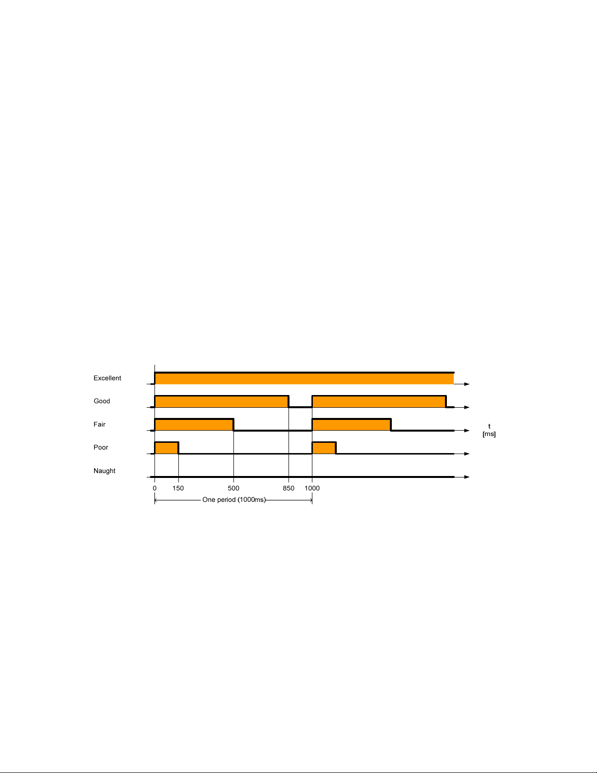
The orange RF signal LED is used during installation to indicate whether the
Street Light Bridge module can establish RF communications with a nearby
Street Light Bridge module. If so, the RF signal flashes in a pattern that
represents the signal quality, as shown in
on page 72 for more information about using the Segment
Figure 4.
Figure 4. RF Signal Quality as Represented by the RF Signal LED
The flashing pattern of the RF signal LED allows the installer to confirm good
RF communications with nearby Street Light Bridge modules without having to
return to the Segment Controller.
However, these RF communications could possibly be with an unrelated street
lighting network that uses a different
which you installed the Street Light Bridge module. Thus, you should ensure
that the Street Light Bridge module can communicate with its Segment
Controller.
By default, both LEDs turn off after one hour. You can modify this timeout value
by updating the nciLedTimeout configuration network variable. Setting this
configuration network variable to zero disables LED shutoff (that is, the LEDs
remain on or flashing indefinitely).
Street Light Bridge Integrator’s Guide 23
Segment Controller than the network into
Page 24

Example Installations
You can install Street Light Bridge modules in almost any configuration to
provide power line and radio frequency communications for street lights within a
street lighting solution.
In the figures, the arrows represent RF communications between the Street Light
Bridge modules. Although the street lights in the figures are shown in straight
lines, they could be in any physical configuration.
Basic Installation
Figure 5 shows a basic installation with a Segment Controller and two Street
Light Bridge modules. The Segment Controller uses the power line
communications channel for the nearest set of luminaires, and two Street Light
Bridge modules provide the communications bridge across the service
distribution transformer to cross electrical phases.
Figure 5. Basic Street Light Bridge Installation
Extending a Basic Installation
A single Street Light Bridge module can communicate with more than one
companion Street Light Bridge module to define a more complex configuration.
Figure 6 on page 25 shows an extension to the configuration shown in Figure 5.
A single Street Light Bridge module communicates with three Street Light
Bridge modules to further extend the range of the Segment Controller and
provide communications to a greater number of luminaires.
communications with luminaires that do not share a power line connection with
the Segment Controller.
24 Installation for the Street Lighting Solution
Figure 6 also shows
Page 25

Figure 6. Extending the Street Light Bridge Installation
Adding Multiple RF Hops
Because Street Light Bridge modules provide communications across power line
boundaries, you can connect them in a series to provide maximum range
extension.
Figure 6. By adding Street Light Bridge modules in series as shown in the
bottom portion of
line and RF communications for almost any physical configuration of luminaires
in a street lighting solution.
Figure 7 shows such an extension from the configuration shown in
Figure 7, you can create complex networks to provide power
Figure 7. Adding Multiple RF Hops
Street Light Bridge Integrator’s Guide 25
Page 26

26 Installation for the Street Lighting Solution
Page 27

Setting Up the Segment Controller
This chapter describes the tasks required to set up the Segment
Controller.
3
Street Light Bridge Integrator’s Guide 27
Page 28
Placing the Segment Controller in Standalone Mode
A street lighting network is a power line repeating network, which requires that
the Segment Controller operate in standalone mode. This mode allows the
Segment Controller to operate as the exclusive network manager of the system,
and to establish and maintain the appropriate repeating chains. A
is the path a message must travel on the PL-20 or RF channel from the
chain
Segment Controller to one or more repeating devices (luminaires or Street Light
Bridge modules) before reaching the target device (a luminaire or a Street Light
Bridge module).
In standalone mode, the Segment Controller controls the network management
commands sent to the devices attached to its channel (note that for a network
operating in LNS mode, LNS would handle these commands). In standalone
mode, the Segment Controller can directly download the application image file to
the devices and commission, set the application state (online/offline), wink, test,
and reset the devices attached to its channel.
repeating
Placing a Network in Standalone Mode
To set a network to standalone mode using the SmartServer Web pages, perform
the following steps:
1. Open the SmartServer Web pages, as described in Chapter 3 of the
SmartServer 2.0 User’s Guide
2. Click the Net network to display the Lon Display Property page.
3. From the Setup tab, select Standalone.
4. Click Submit. A dialog appears informing you that the SmartServer is
switching to standalone mode.
It could take several minutes for the SmartServer to switch to standalone mode.
After the SmartServer has switched to standalone mode, the dialog closes and
you can continue preparing your SmartServer for the network installation.
.
Network Limitations in Standalone Mode
Managing a power line repeating network in standalone mode has the following
restrictions:
i.LON
• Network is limited to a maximum of approximately 200 devices.
• Network is limited to a single channel.
28 Setting Up the
Segment
Controller
Page 29

• Network cannot have a router attached to the channel.
• Network does not use LNS management.
• Devices cannot be configured with LNS Plug-ins
• Network cannot be connected to any other network management tool
through the network interface or remote network interface.
• L
ONWORKS network variable connections are not supported. A network
in standalone mode functions strictly as a master-slave system. This
differs from the standard LNS mode in which the devices attached to the
SmartServer’s channel can communicate with each other and the
SmartServer in a peer-to-peer manner.
Configuring the LonWorks Channel for Power Line Repeating
For a power line repeating network, the LON channel attached to the
SmartServer must be configured as a PL-20C or a PL-20N channel and repeating
must be enabled on the channel. To configure the channel, perform the following
steps:
1. Expand the Net network, and then click the LON channel to display the
Lon Network Property page.
2. From the Setup tab, select the PL-20C, PL-20N, or other appropriate
channel type from the Channel Type dropdown listbox.
Important: The channel type that you select must match the channel
type required by local regulations for the area of device deployment. The
channel type must also match the channel settings for all devices that
will participate in power line communications with the Segment
Controller.
3. Select the Repeating checkbox to enable repeating on the channel.
4. If a network message fails, a data point and its device are marked offline.
You can select the Use Minimal Offline Time checkbox so that all the
data points on the offline device with pending network messages
(read/write requests, polls, or heartbeats) are marked offline and network
messages are not sent to them. Thus, network performance is not
impacted by an offline device.
You can also set the minimum period of time (in seconds) that the
SmartServer waits before transmitting network messages to offline data
points. During this period, an offline device transmits an OFFLINE
Street Light Bridge Integrator’s Guide 29
Page 30

status in response to data point requests. After the Minimal Offline Time
elapses, the SmartServer sends a read/write request to one offline data
point. If the read/write request succeeds, the data point and its device
are marked online, and all cached read/write requests for the offline data
points on the device are executed. If you do not configure this property on
a power line repeating channel, it is set to 60 seconds.
5. Optionally, you can set the Use Offline Delay property to specify the
period of time (in seconds) that the SmartServer waits before marking a
data point and its parent device offline (red) in the SmartServer tree after
the LON driver detects that the data point is offline.
For example, if you poll a data point every 5 minutes and you set Use
Offline Delay to 1 hour, it takes 12 polls for the data point and its parent
device to be marked offline—even though the LON driver detected that it
could not communicate with the data point after the first poll.
6. Optionally, you can click Advanced to set the retry timer and retry counts
that determine the frequency in which network messages are re-sent to a
device after no confirmation of delivery is received. Although you can
change these properties, it is recommended that you use the default
transmit timer (512 ms) and the default retry count (3).
7. Click Submit.
Copying Resource Files
The Segment Controller needs a copy of the resource files for each device type
(luminaire and Street Light Bridge module) in the street lighting network. You
can obtain the appropriate resource files for the Street Light Bridge modules
from the Echelon Web site; you can obtain the appropriate resource files for each
luminaire type from the manufacturer.
To copy these files to the Segment Controller:
1. Open an FTP connection to the Segment Controller. See the
SmartServer 2.0 User’s Guide
the SmartServer.
2. Copy the files from the downloaded (or otherwise provided) resource file
to the /lonworks/Import and /lonworks/types folders in the SmartServer.
For the /lonworks/Import folder, Street Light Bridge module files are
copied to the /Echelon subfolder. For a luminaire, its files are copied to a
folder defined by the manufacturer.
for more information about using FTP with
Automatically Discovering Devices
If you want the Segment Controller to automatically discover and commission
luminaires and Street Light Bridge modules within the network, you can place
the Segment Controller in Acquisition Mode. To enable this mode, perform the
following steps:
i.LON
1. Open the SmartServer Web pages, as described in Chapter 3 of the
SmartServer 2.0 User’s Guide
30 Setting Up the
.
Segment
i.LON
Controller
Page 31

2. Click the Tools icon to open the Tools dialog.
3. From the Tools dialog, click Street Light Bridge Installation to open the
Lon Devices page.
4. From the Lon Devices page, click the … button at the top of the page to
open the LON Scan Settings dialog.
5. Select the Predictive Scanning checkbox. You can also specify the
maximum hop count for repeating chains; the default is 8. Click OK to
close the dialog and return to the Lon Devices page.
6. Select the Continuously checkbox to initiate continuous scanning.
Alternatively, click Scan to initiate a one-time scan. The SmartServer
will discover any unconfigured street light devices or Street Light Bridge
modules and commission them.
7. When all street light devices and Street Light Bridge modules have been
successfully commissioned, deselect the Continuously checkbox to return
the Segment Controller to Operational Mode. You can also close the Lon
Devices page and return to the main SmartServer page.
All devices that have been commissioned are automatically added to the
SmartServer tree, under the LON icon.
While in Operational Mode, if you need to add devices to the street lighting
network, you can add them manually and use the SmartServer Web pages to
5,
commission them, as described in Chapter
Network
, on page 47.
Managing a Street Lighting
Street Light Bridge Integrator’s Guide 31
Page 32

32 Setting Up the
Segment
Controller
Page 33

4
Planning for the Street Lighting
Solution
This chapter includes information needed for planning a street
lighting network.
Street Light Bridge Integrator’s Guide 33
Page 34

Security Planning
Security planning for a street lighting network must address both of the
following concerns:
• Physical security of the luminaires, Street Light Bridge modules, and the
Segment Controller
• Network communications security
This document does not describe planning for physical security. The luminaires
do not require extra security to participate in a street lighting network. Because
the Street Light Bridge modules are typically installed on or near the luminaires,
they have minimal physical security requirements. The Segment Controller
should be installed in a secure location, within communications distance of the
street lighting network.
Network communications security must consider:
• Power line communications between the Segment Controller and the
street lighting network (luminaires, Street Light Bridge modules, and
possibly other Segment Controllers)
• Power line communications between luminaires
• Power line communications between Street Light Bridge modules
• Radio frequency communications between Street Light Bridge modules
In addition, network communications security must address communications
between Segment Controllers and between Ethernet or Internet devices and
Segment Controllers. See the
information about network communications security for the Segment Controller.
i.LON SmartServer 2.0 User's Guide
General Network Communications Security
Devices within a street lighting network communicate over the power line
channel using an open-standard protocol, the ISO/IEC 14908-1 Control Network
Protocol. Power line communications are not encrypted; however, messages sent
within a general power line network between devices can use authentication to
prevent unauthorized access to devices and their applications. Devices within a
street lighting network generally do use authentication, as defined by the
ISO/IEC 14908-1 Control Network Protocol, for power line communications.
Street Light Bridge modules communicate over an RF channel using a private
protocol. RF communications are not encrypted; however, the Street Light
Bridge modules always use authentication within the RF channel to prevent
unauthorized access to the devices and their applications. For RF-channel
authentication, the Street Light Bridge firmware uses a cryptographic hash
function, the Secure Hash Algorithm (SHA), described by the National Institute
of Standards and Technology (NIST) Federal Information Processing Standards
Publication 180-2 (FIPS PUB 180-2). This hash function ensures that a Street
Light Bridge module accepts messages only from another Street Light Bridge
module.
for more
In addition, Street Light Bridge modules provide the following security measures
for the RF channel:
34 Planning for the Street Lighting Solution
Page 35

• Each message includes the sender’s RF address to detect simple
intrusion.
• Each message contains a 32-bit sequence number that allows for
duplicate detection and protection against replay attacks.
Network Security for Device Installation
When installing devices within a power line network, you have the following
options for managing authentication security:
• No security for the devices
• Security is configured (in a pre-deployment facility) before devices are
installed
• Security configured (in the field) after devices are installed
For a street lighting network, having no authentication security is not
recommended because the network is generally deployed with minimal physical
security. When you configure security for the devices depends on your network,
but typically, security is configured after installation.
If you configure security after installation, your network must include two
domains: one for device discovery and one for normal communications. In this
case, both domains use the same subnet/node address. Domain index 1 would be
the discovery domain, which the Segment Controller would use to discover and
commission each device (luminaires and Street Light Bridge modules). If
security is not required for your network, your network can use a single domain
for both discovery and normal communications.
In addition, because ISO/IEC 14908-1 authentication uses distributed
authentication keys, you must consider how to manage the number and
distribution of the keys:
• Each device (luminaire and Street Light Bridge module) has its own
unique key assigned before installation
• Each Segment Controller has a unique key, but the luminaires and Street
Light Bridge modules have non-unique keys (different from the Segment
Controller’s key)
• All devices within the street lighting network have the same key (a citywide key)
In general, assigning a unique key to each device in the street lighting network
before installation is unnecessary. Assigning one key to all devices within the
network is a valid option; be sure to document that key so that the network can
be expanded over time. For most street lighting networks, assigning a unique
key to each Segment Controller, and non-unique keys to all other devices, is the
most economical and secure method. From the Segment Controller, you can
increment the keys for the other devices so that each one has a unique key if you
require additional security.
For a secure network (one in which security is configured before devices are
installed), each device must be defined with the configured and authenticated
attributes set. That is, each device added to the street lighting network must be
ONWORKS configured device and must use authentication. If security is less
a L
Street Light Bridge Integrator’s Guide 35
Page 36

important, the devices can be in the unconfigured state before installation and be
configured during commissioning. In both cases, authentication is recommended.
Device Upgrade Planning
To allow your street lighting network to be upgraded over time, you can download
an updated Street Light Bridge application (as Echelon releases application
updates) over the power line network. The application download uses the
standard ISO/IEC 14908-1 download protocol.
The application download process includes the following steps:
• The Street Light Bridge detects the start of a download by a transition to
the applicationless state.
• The Segment Controller then downloads the application, which is stored
in onboard flash memory.
• After the download is complete, the Street Light Bridge firmware
computes a checksum of the downloaded application image to verify that
the download was successful. If the checksum fails, the Street Light
Bridge firmware sends a failure response to the “go unconfigured” request
that follows the computation of the checksum. In this case, you should
begin a new download for the application or contact Echelon Support.
• The Street Light Bridge firmware transfers the application image from
off-chip to on-chip flash.
• The Street Light Bridge resets and begins running the new application
image.
Note that although you can upgrade the Street Light Bridge application over the
network, you cannot upgrade the Street Light Bridge firmware over the network.
Network Management Planning
Planning for a street lighting network involves tasks for the luminaires, the
Street Light Bridge modules, and the Segment Controller. In addition, you need
to plan for both power line channels and RF channels for the Street Light Bridge
modules.
Although a Street Light Bridge module provides options for configuring the
network, many networks can operate successfully using default settings, without
additional configuration.
5,
See Chapter
about network planning for the Segment Controller.
Managing a Street Lighting Network
Defining the Networking Channels
A Street Light Bridge module uses the Institute of Electrical and Electronics
Engineers (IEEE) wireless personal area network standard 802.15.4 for its radio
frequency (RF) communications. The standard defines up to 16 channels in the
2.4 GHz industrial, scientific and medical (ISM) radio band.
, on page 47, for information
A Street Light Bridge module creates a virtual RF channel by using broadcast
messages, transmitting and receiving unfragmented packets. To define an RF
36 Planning for the Street Lighting Solution
Page 37

channel, all the Street Light Bridge modules within a street lighting network
coordinate which frequencies they use. Multiple Street Light Bridge modules can
use a single RF channel. In addition, multiple RF channels can exist within a
single street lighting network.
A Street Light Bridge module identifies these channels through a pair of
configuration network variables (nciPriChs and nciSecChs), which define three
channels in the range 11..26, with default values for the primary channel of 25,
20, and 15, and default values for the secondary channel of 11, 17, and 26. The
two configuration network variables represent the primary (normal) and
secondary (alternate) LonTalk (ISO/IEC 14908-1) path, which allow the
transceiver to define a primary and a secondary channel for communications. If
communications fail on the primary channel, the Street Light Bridge module can
switch to the secondary channel. The secondary frequency is used when the
Segment Controller requests that the alternate path be used.
Important: For all Street Light Bridge modules within the street lighting
network, the set of defined primary channels must match for all Street Light
Bridge modules, and the set of defined secondary channels must match for all
Street Light Bridge modules. In general, the primary and secondary channels
should not be the same.
A Street Light Bridge module broadcasts a packet once, followed by a number of
repeats (the default number is 1; you can modify the nciPriRpt and nciSecRpt
configuration network variables to specify additional repeats) on each of the
configured RF channels. For each path, the product of the number of configured
channels and the repeat count plus one should not exceed 12. The default is 6
(three channels with one repeat). Thus, for three configured channels, you
should define no more than three repeats.
Signal Strength
The Segment Controller Power Line Repeating Analysis Web page shows device
signal strength and margin information. When a Street Light Bridge module is
used for power line repeating, the Web page shows power line signal strength
and margin information. When the Street Light Bridge module is used for RF
repeating (or both power line and RF repeating), you can also retrieve RF signal
strength and margin information; see
Network
on page 54.
Analyzing a Power Line Repeating
Defining the Media Access Protocol
Each Street Light Bridge module has its media access protocol pre-programmed
in the factory. For European street lighting networks, the Street Light Bridge
module uses the comité européen de normalisation electrotechnique
(CENELEC) EN50065-1 media access protocol for power line networks. For
other geographies, the CENELEC protocol is not used.
For device testing, or for power line networks that do not connect to public mains
power lines, you can decide to enable or disable the use of the CENELEC protocol
for a Street Light Bridge module. From the Segment Controller, you can change
5
European Committee for Electrotechnical Standardization
5
Street Light Bridge Integrator’s Guide 37
Page 38

the value of the nciMediaAccess configuration network variable to specify the
power line media access protocol:
• 0 (default): The Street Light Bridge module uses the media access
protocol setting defined in the firmware. That is, European models use
the CENELEC protocol, and other models do not.
• 1 (normal): The Street Light Bridge module uses the communication
parameters of a PL-20N device. That is, the CENELEC EN50065-1
media access protocol is
20N channel. The XIF file for this mode is slb-normal.xif.
• 2 (cenelec): The Street Light Bridge module uses the communication
parameters of a PL-20C device. That is, the CENELEC EN50065-1
media access protocol is
20C channel. The XIF file for this mode is slb-cenelec.xif.
Changing the value of this configuration network variable overrides the setting
maintained in the device firmware. Changes to this configuration network
variable require a device reset, and that all devices (luminaires, Street Light
Bridge modules, and the Segment Controller) within the same network use the
same media access protocol setting.
disabled
enabled
. The device program ID reports a PL-
. The device program ID reports a PL-
Preparing the Segment Controller
To prepare a Segment Controller for a street lighting network, perform the
following tasks:
1. Place the SmartServer in standalone mode; see
Controller in Standalone
2. Enable the SmartServer to manage a power line repeating network; see
Mode on page 28.
Placing the Segment
Configuring the LonWorks Channel for Power Line Repeating
3. If the network configuration is known, or if device security is configured
before the devices are installed (that is, in a pre-deployment facility),
enter the Neuron IDs of all of the Street Light Bridge modules and
luminaires for the network.
4. If the network configuration is not known, or if device security is
configured after the devices are installed (that is, in the field), place the
SmartServer in acquisition mode so that it can discover and commission
all devices within the network; see
30.
page
5. Copy the resource files for streetlight devices (luminaires and Street
Light Bridge modules) within the network to the /lonWorks/Import folder.
6. Back up the SmartServer database; see the
User's Guide
folder; for a local backup (for example, in a pre-deployment facility), you
should back up all folders within the SmartServer.
. For a remote backup, you could back up just the /config
Automatically Discovering Devices
i.LON SmartServer 2.0
Preparing the Street Light Bridge Modules
on page 29.
on
To prepare a Street Light Bridge module for a street lighting network, perform
the following tasks:
38 Planning for the Street Lighting Solution
Page 39

1. If the network configuration is known, or if device security is configured
before the devices are installed (that is, in a pre-deployment facility),
define the authentication key for the device. You can use any 12-byte
(96-bit) key.
2. If the network configuration is not known, or if device security is
configured after the devices are installed (that is, in the field), note the
Neuron ID for the device (printed on the module) so that you can match
the installed location of the Street Light Bridge module with its Neuron
ID in the Segment Controller.
3. Define which domains the device should use for normal communications.
You can use any 1-, 3-, or 6-byte domain, but a 6-byte domain is
recommended; for example, you could use the 6-byte Neuron ID of the
Segment Controller as the network segment domain. If security is not
required for your network, each device can use a single domain for both
discovery and normal communications.
Preparing the Luminaires
To prepare a luminaire for a street lighting network, perform the following tasks:
1. If the network configuration is known, or if device security is configured
before the devices are installed (that is, in a pre-deployment facility),
define the authentication key for the device. You can use any 12-byte
(96-bit) key.
2. If the network configuration is not known, or if device security is
configured after the devices are installed (that is, in the field), note the
Neuron ID for the device (generally printed on or attached to the device)
so that you can match the installed location of the luminaire with its
Neuron ID in the Segment Controller.
3. Define which domains the device should use for device discovery and for
normal communications. You can use any 1-, 3-, or 6-byte domain, but a
6-byte domain is recommended; for example, you could use the 6-byte
Neuron ID of the Segment Controller as the network segment domain. If
security is not required for your network, each device can use a single
domain for both discovery and normal communications.
Device Discovery
Before the Segment Controller can discover and commission luminaires and
Street Light Bridge modules within the street lighting network, you must place
the Segment Controller in acquisition mode; see
Devices
If you install the Segment Controller before installing any luminaires or Street
Light Bridge modules, you can pre-define each luminaire or Street Light Bridge
module within the Segment Controller. In this case, the Segment Controller
discovers and commissions each device as it is installed. For any devices that the
Segment Controller cannot discover, you can install a Street Light Bridge module
to extend the communications range so that the device can be discovered.
on page 30 for more information.
Automatically Discovering
If you install luminaires or Street Light Bridge modules before installing their
corresponding Segment Controller, the Segment Controller must discover and
Street Light Bridge Integrator’s Guide 39
Page 40

commission all luminaires and Street Light Bridge module in the entire street
lighting network. The Segment Controller discovers and commissions nearby
devices first, then discovers additional devices through the Street Light Bridge or
luminaire repeaters, and then commissions them. Thus, the discovery and
commissioning process is iterative, and could take some time to complete. The
process also depends on your having installed Street Light Bridge or luminaire
repeaters in appropriate positions within the network.
Both installation methods are supported, and both work well in most cases. The
first method is recommended for new installations because it allows you to create
and document the network as you install it. For either installation method, you
can manually commission any device within the network if you have the device’s
Neuron ID.
Defining Repeating
The main purpose of a Street Light Bridge module is to act as a repeater for
power line communications, for RF communications, or for both. By repeating
the communications packets, the Street Light Bridge module can extend the
overall range of the street lighting network, or it can bypass obstacles that could
otherwise restrict communications within the network.
What kind of repeater the Street Light Bridge becomes depends on the value of
the nciRepeatMode configuration network variable:
• If nciRepeatMode is 0, proxy requests received on the power line channel
are repeated onto the RF channel. This is the default value.
• If nciRepeatMode is 1, no packets are sent on the RF channel (that is, the
Street Light Bridge module acts as a power line repeater only).
• If nciRepeatMode is 2, no packets are sent on the power line channel
(that is, the Street Light Bridge module acts as an RF repeater only).
Regardless of the Street Light Bridge module’s repeating mode, when it receives
a message that requires a response, acknowledgement, challenge, or reply, the
Street Light Bridge module sends that response, acknowledgement, challenge, or
reply on the channel on which the original message was received.
PL/PL Repeater
You can define the Street Light Bridge module as power line repeater to extend
the range of power line communications. By default, the Street Light Bridge
module acts as power line repeater, but by setting nciRepeatMode to 1, you can
block RF communications, which might be useful for situations in which RF
communications are not used.
Figure 8 shows an example for PL/PL repeating mode. In a multi-phase system
with insufficient cross-coupling between the phases, a pair of Street Light Bridge
modules in PL/PL repeating mode act as intelligent phase couplers.
40 Planning for the Street Lighting Solution
Page 41

Figure 8. PL/PL Repeating
RF/RF Repeater
You can define the Street Light Bridge module as an RF repeater to extend the
range of RF communications. If you set nciRepeatMode to 2, you block power line
communications, which can be useful if the Street Light Bridge module should
act as a repeater for a different Segment Controller than the one with which it
has power line communications.
Figure 9 shows an example for RF/RF repeating mode. The street lighting
network on the left side of the figure (shown in purple) is installed and running.
Then, install the street lighting network on the right side of the figure (shown in
blue). If SLB A and SLB B cannot establish RF communications, you can install
an RF/RF repeater (SLB X) between them. By defining SLB X as an RF/RF
repeater, it does not interfere with power line communications on its own power
line network (the purple network).
Figure 9. RF/RF Repeating
PL/RF Repeater
In normal mode, the Street Light Bridge module serves both power line and RF
channels according to the following rules:
Street Light Bridge Integrator’s Guide 41
Page 42

• When receiving a message, the Street Light Bridge module replies only
• When receiving a proxy request, the Street Light Bridge module forwards
A Street Light Bridge module does not repeat a packet onto the RF channel
unless it receives a request from the Segment Controller to repeat. When
directed to repeat onto the RF channel, the receiver waits until all the retries
from the originator have completed before repeating onto the same channel.
Thus, a Street Light Bridge module attempts to keep the RF channel clear while
another module is using it, and does not send responses while the originator is
busy sending repeats of the request.
The Street Light Bridge module uses information in each packet header to detect
packet duplication, replay attacks, and network intrusion.
Scheduling
The Segment Controller includes an Event Scheduler application that you can
use to schedule events. Thus, for example, you can schedule luminaires to turn
on at sundown, dim at the end of the evening rush hour, brighten at the start of
the morning rush hour, and then turn off at sunrise. In general, you would not
define an event schedule for Street Light Bridge modules (they should run
continuously).
on the channel on which the message was received (PL or RF). In this
case, “reply” means response, acknowledgement, challenge, or reply.
the request to both the RF and PL channels.
6,
See Chapter
information about scheduling.
Controlling a Street Lighting Network
, on page 77, for more
Device and Network Recovery Planning
The Street Light Bridge module has a watchdog mechanism that covers the main
processor, the Smart Transceiver, and the radio communication chip. That is, if
LonTalk (ISO/IEC 14908-1) communications are lost, the Smart Transceiver
resets; if the radio communications are lost, the radio communication chip resets.
Figure 10 shows a simple street lighting network with two Street Light Bridge
modules. This section considers two recovery scenarios: loss of SLB A or loss of
SLB B. For any extended outage (generally longer than 15 minutes), the
Segment Controller should report the outage so that network management
personnel can investigate and repair the outage.
Figure 10. An Example Street Lighting Network
These scenarios assume that both SLB A and B have the same RF channel lists
(primary 25, 20, 15 and secondary 11, 17, 26) – an assumption that should apply
to nearly all street lighting networks. Also, these scenarios assume that the
network has good communications prior to device failure.
42 Planning for the Street Lighting Solution
Page 43

Scenario 1: Loss of SLB A
When SLB A fails (for example, it experiences a power outage), any
communications initiated by the
street light (SL).
At this point, SLB B determines that the RF channel is idle. After the channel
has been idle for 15 minutes, SLB B tunes to another channel from its configured
channel list. If that channel is also idle, SLB B cycles through all of its
configured channels to attempt to reestablish communications. SLB B cycles
through all of its defined channels until SLB A rejoins the network.
When SLB A becomes active, SLB A and SLB B negotiate a new primary channel
for communications. Because the two Street Light Bridge modules are likely not
to be using the same channel at the same time when SLB A rejoins the network,
both cycle through their defined channels until communications are established.
By default, the cycle time is approximately 3 minutes for each channel.
If SLB A had been offline for less than 15 minutes, RF communications would be
reestablished immediately because SLB B would not have switched from the
original channel and SLB A, after it becomes active, would use the same channel.
Segment Controller cannot reach SLB B or the
Scenario 2: Brief Loss of SLB B
If SLB B experiences a brief outage (less than 15 minutes), communications
between the Segment Controller and SLB B or the street light (SL) fail. When
SLB B becomes operational, RF communications are reestablished quickly as the
devices negotiate the use of the channel.
Scenario 3: Prolonged Loss of SLB B
If SLB B experiences an extended outage (longer than 15 minutes),
communications between the Segment Controller and SLB B or the street light
(SL) fail. SLB A detects an idle channel, and begins cycling through the channel
list. If the Segment Controller continues to attempt to communicate with SLB B,
SLB A delays cycling through the channels until the number of failed messages
equals the retry count.
When SLB B becomes operational, it uses its last-known-good channel. If the
Segment Controller has not switched the path (for example, from normal to
alternate), one of the message retries should succeed as SLB A cycles through the
configured channel list. Otherwise, SLB A and SLB B negotiate a new primary
channel for communications. The channel negotiation for downstream
communications (from the Segment Controller) is fairly quick because it
alternates between the primary and the alternate path. For upstream
communications (to the Segment Controller), message retries guarantee that
communications are reestablished.
If the Segment Controller has marked SLB B as “Confirmed Down” (see
Analyzing a Power Line Repeating Network
communications could take additional time, depending on the retry timer for
Confirmed Down devices.
Street Light Bridge Integrator’s Guide 43
on page 54), reestablishment of
Page 44

Simulating Communications Errors
A Street Light Bridge module autonomously determines which frequency to
monitor, and then continues using this frequency until some failure condition
occurs that makes the frequency unusable. When determining which channel to
use, the Street Light Bridge firmware monitors the channel quality and the
signal quality for the channel, and chooses the best transmit and receive channel.
The firmware considers a receive channel bad if the Street Light Bridge module
receives fewer than five valid LonTalk (ISO/IEC 14908-1) packets in a window of
3600 seconds. Street Light Bridge modules send a heartbeat signal periodically
to ensure that the channel is not idle within this window.
Before deploying a street lighting network, or for a field trial, you can simulate
packet errors for receiving messages, transmitting messages, or both. You can
set the simulation mode individually for both the primary and the alternate PL
path and for each of the 16 RF channels.
To enable the error simulation mode, write a non-zero value to both the
nviErrMode and nviErrRate input network variables. By default, both network
variables have a value of 0 (zero) to disable error simulation. The values of these
network variables persist across device reset and power outage.
Writing a non-zero value to the nviErrMode network variable initiates the error
simulation mode, but only if the corresponding error rate, defined by the
nviErrRate network variable, also has a non-zero value. Thus, you can start and
stop error simulation by writing to the nviErrMode network variable.
In addition, error simulation ends after a time period equal to the value of the
nciErrTimeout configuration network variable (a number of minutes, default of
one day, up to a maximum of three days). This timeout value is updated only
while the Street Light Bridge module is powered on; any time spent powered off
is not included in this timeout value.
Because the Street Light Bridge application writes the remaining error
simulation time to onboard flash memory once every 30 minutes, completion of
error simulation might be delayed by up to 30 minutes if the Street Light Bridge
module is powered off or reset during the simulation.
Updating the nviErrRate network variable has the following effect:
• If error simulation is active, the error simulation expiration timer is
restarted with the current nciErrTimeout value. Note that setting the
nviErrRate network variable to zero still causes the error simulation
expiration timer to restart, even though no errors are simulated.
• If error simulation is not active, the value is stored but has no other
immediate effect.
Updating the nviErrMode network variable has the following effect:
• If error simulation is active, and if nviErrMode is not all zeroes, the error
simulation expiration timer is restarted with the current nciErrTimeout
value.
• Setting nviErrMode to all zeroes ends error simulation mode, regardless
of how much time remains.
Updating the nciErrTimeout configuration network variable has the following
effect:
44 Planning for the Street Lighting Solution
Page 45

• If error simulation mode is active, error simulation mode is restarted
with the new timeout value, regardless of how much time has already
passed or how much time would be left in the previous simulation.
• If error simulation mode is not active, the value is stored but has no other
immediate effect.
Note that a value of zero (0) is not valid for the nciErrTimeout configuration
network variable; the Street Light Bridge application rounds a zero value up to 1
(one) to ensure that error simulation mode can eventually end.
Error Codes
The Segment Controller displays the last error code on the Web page for the
Street Light Bridge module. You can also use network management tools to send
a query status message to the Street Light Bridge module to retrieve the error
log. See the
firmware error codes. The Street Light Bridge firmware can also post the errors
listed in
Error Description
Table 1.
Neuron Tools Errors Guide
Table 1. Street Light Bridge Firmware Error Codes
(078-0402-01B) for a listing of Neuron
0x40 Logged when a download fails because the image has a bad CRC, fails to
decompress, or is improperly formed in some way.
0x41 Logged when a download fails because an image is incompatible with the
target. This error includes image incompatibility (for example, not a
Street Light Bridge image), hardware incompatibility, bootrom
incompatibility, or feature incompatibility.
Street Light Bridge Integrator’s Guide 45
Page 46

Page 47

5
Managing a Street Lighting
Network
This chapter describes how to manage a street lighting
network that uses power line repeating.
Street Light Bridge Integrator’s Guide 47
Page 48

Manually Installing a Street Lighting Network
You can manually install a street lighting network using the SmartServer Web
pages (see
installing devices automatically). The installer should create a device list that
accurately records the device location, such as light pole number, and the Neuron
ID of the device installed at that location. For example, the installer can peel a
bar code sticker off the device and record its location next to the bar code, or just
record the device location and the Neuron ID. With the SmartServer Web pages,
the network installation includes the following steps, which are each described in
the subsequent sections:
1. Create the devices.
2. Manually enter the locations and Neuron IDs of the devices to be
3. Select the devices to be installed.
4. Enable smart network management for the selected devices. After smart
Automatically Discovering Devices
installed.
network management is enabled, the SmartServer automatically loads,
commissions, and sets the devices online. You can then check the
installation status using the LON Command Queue Web page.
on page 30 for information about
Creating Devices
To create a device, perform the following steps:
1. Expand the Net network, right-click the LON channel, and select Add
Device from the shortcut menu to open the Add Device dialog.
48 Managing a Street Lighting Network
Page 49

2. Enter the following device properties: the name of the device (for
example, “Oak Creek Road Lamp 46N”), the location of the device (select
External), and the XIF file for the device (for example, “slb-normal”).
3. Click OK to add the device. It is added to the tree of its parent channel.
4. Click Submit on the main SmartServer page to accept the change to the
network.
5. Repeat steps 1–4 for each device on the network to be installed.
Entering Device Locations and Neuron IDs
Use the SmartServer Web pages to enter the locations and Neuron IDs of the
devices being installed:
1. Select the device from the LON device tree to display the device page.
2. From the Setup tab, specify the 12-digit hex string comprising the
device’s Neuron ID in the Neuron ID field.
3. You should also enter a description of the device location such as a light
pole number or GPS coordinates that can be associated with the device in
the Geographical Position field.
4. Click Submit. The SmartServer discovers the repeating path for the
device and commissions it.
5. Repeat steps 1–5 for each device on the network to be installed.
Selecting Devices
After entering the locations and Neuron IDs of the devices to be installed, you
select those devices on the tree:
Street Light Bridge Integrator’s Guide 49
Page 50

1. Select one or more devices from the tree to be installed.
• To select one device, click that device.
• To select multiple devices, click one device and then either hold down
CTRL and click all other devices to be installed or hold down SHIFT
and select another device to install the entire range of devices.
2. The device page opens. Proceed to the next section,
with Smart Network Management
, to install the devices.
Installing Devices
Installing Devices with Smart Network Management
After you select the devices to be installed, use the Smart Network Management
feature to install them. With this option, the SmartServer asynchronously sets
the following device properties to the states it determines to be desired:
• Program ID
• Commission status (commissioned or decommissioned)
• Application state (online or offline)
• Application image
• Device template (external interface)
• Configuration property default values
Enabling Smart Network Management
You can enable smart network management for a device by selecting the
checkbox at the top of the SNM column of the device page (setup tab), and then
clicking Submit. You can also enable smart network management for specific
device properties by selecting the checkbox in the SNM column for the specific
property, and then clicking Submit. Which checkboxes you should select depends
on whether you are installing devices pre-loaded with the current application
image files:
• If you are installing pre-loaded devices, select the Smart Network
Management checkboxes for the following properties: Commission
Status, State, Template, Write Configuration Property Defaults, and
Reset. Verify that all other checkboxes are cleared to ensure that the
SmartServer does not update the application image currently on the
devices.
• If you are installing devices that need to be loaded with an application
image file, select the checkbox at the top of the SNM column to enable
smart network management for all device properties. Note that the
application image to be downloaded to the devices must be in the
/LonWorks/Import folder on the SmartServer flash disk for the
SmartServer to install the devices successfully.
After smart network management is enabled for a device property, the
SmartServer attempts to perform the corresponding network management
command. The current statuses of the network management commands appear
in the Progress column.
50 Managing a Street Lighting Network
Page 51

Installing Devices
After enabling smart network management for all the applicable device
properties, click Submit. The SmartServer performs the following tasks for each
device that you are installing:
1. Fetches the program ID of the device (if the Smart Network Management
checkbox is selected for the Program ID property).
2. Downloads the application image file to the device (if the Smart Network
Management checkbox is selected for the Application Image property).
The SmartServer downloads the application image file that has a
program ID matching that of the device application; the application
image file must be in the /LonWorks/Import folder.
3. Loads and instantiates the device interface (if the Smart Network
Management checkbox is selected for the Template property):
a. The SmartServer first attempts to load the device template (.XML
file) that has a matching program ID; the device template must be in
the /config/template/lonworks folder on the flash disk.
b. If the SmartServer cannot find a matching device template, the
SmartServer loads the device interface (XIF) file that has a matching
program ID; the XIF file must be in the /LonWorks/Import folder.
c. The SmartServer creates all the functional blocks and data points
defined by the device interface.
4. Re-commissions the device. Commissioning downloads network
configuration data and application configuration data to the device.
5. Writes configuration property default values defined in the XIF file to the
device.
6. Resets the device, which starts the device application.
7. Sets the device application online.
Checking Device Installation Status
You can use the LON Command Queue Web page to check the status of the
management commands you have submitted for one or more devices:
1. Right-click the local SmartServer icon, select Setup, and select LON
Command Queue from the shortcut menu. Alternatively, you can click
the Tools icon and select LON Command Queue.
Street Light Bridge Integrator’s Guide 51
Page 52

2. The LON Command Queue page opens.
3. The management commands submitted for all devices and their statuses
appear in a table. By default, the names of the first 20 devices listed in
the tree in the left frame are listed in descending alphabetical order and
the commands executed on them are listed in descending chronological
order (most recent to earliest). You can sort the management commands
by clicking the column headers.
To view multiple additional devices, click a device in the tree, and then
either hold down CTRL and click all other additional devices to be
viewed, or hold down SHIFT and select another device to view the entire
range of additional devices.
To view the status of a specific device, click one of the 20 blue-highlighted
devices in the tree to clear the pre-selected devices and then click the
device to be viewed. To view the statuses for a set of specific devices,
click one of the 20 blue-highlighted devices in the tree to clear the preselected devices, click a device in the tree, and then either hold down
CTRL and click all other devices to be viewed, or hold down SHIFT and
select another device to view the entire range of devices.
52 Managing a Street Lighting Network
Page 53

4. You can right-click the header, a table entry, or an empty space in the
application frame and select one of the following options from the
shortcut menu:
Clear Table
Configure
Device
Cancel
Command
Clears all entries in the LON Command Queue table. The table
automatically re-lists pending commands (STATUS_REQUEST)
and updates their statuses after the commands successfully
complete or fail.
Opens the Driver or General properties page for the selected
device.
Cancels the selected command and deletes it from the table. You
can select multiple commands by clicking one, holding down
CTRL, and clicking the other commands to cancel. You can also
use this option to delete inactive commands from the table.
Troubleshooting Street Lighting Network Installation
If a device is not installed by the SmartServer even after the entire network
installation has been completed, it is likely that the device has failed or the
SmartServer cannot reach it through a repeating device. In this case, you can do
the following:
1. Add another device (such as a Street Light Bridge module) at an
intermediate spot on the network that will serve only as a repeater. See
Adding Devices
an installed power line repeating network.
on page 64 for more information about adding devices to
2. Replace the device to determine if it has failed. See
67 for more information about replacing devices on a power line
page
repeating network.
Maintaining a Street Lighting Network
You can perform routine maintenance to update, repair, and optimize an
installed street lighting network. You can use the SmartServer to maintain the
network and its devices. For example, if a device fails, you can replace it on the
physical network and then logically replace it on the SmartServer, preserving the
device’s configuration.
This section describes the following network maintenance tasks that you can
perform with the SmartServer:
• Analyze the power line repeating network using the Power Line
Repeating Analysis Web page
• Adding devices
• Upgrade devices
• Replace devices
• Decommission devices
Replacing Devices
on
Street Light Bridge Integrator’s Guide 53
Page 54

• Set devices offline
• Test (query and wink) devices
• Delete devices
Analyzing a Power Line Repeating Network
When running on a PL-20 repeating network, the SmartServer transmits
network messages to the repeating devices with which it can directly
communicate, and those repeating devices in turn relay the messages to
repeating devices located further down the power line, and so on until the
message reaches the target device. The following figure illustrates a repeating
chain that could be used to relay a network management command from the
SmartServer to a target device. In this example, the repeating chain consists of
Repeating Device 1 (a Street Light Bridge module), which relays the message to
Repeating Device 2 (a repeating-enabled luminaire), which relays the command
to Repeating Device 3 (a Street Light Bridge module), which relays the message
to the target device (a luminaire). A luminaire enabled for repeating would use
power line repeating. A Street Light Bridge module could use power line
repeating or forward the message using an RF channel to another Street Light
Bridge module.
PL-20 Channel
Device
Repeating
Device 1
Repeating
Device 2
Hop Hop Hop
Device
Repeating Chain
Repeating
Device 3
Figure 11. Repeating Network
You can use the Power Line Repeating Analysis Web page to view the repeating
chain a device is using to communicate with the SmartServer. In addition, you
can use this Web page to analyze and debug the power line repeating network.
To open and use the Power Line Repeating Analysis Web page, perform the
following steps:
Target
Device
54 Managing a Street Lighting Network
Page 55

1. Right-click the SmartServer icon, select Setup, and select Power Line
Repeating Analysis from the shortcut menu. Alternatively, you can click
the Tools icon and select Power Line Repeating Analysis.
2. The Power Line Repeating Analysis Web page opens.
The rows in this Web page represent established repeating paths between
the listed devices. The target device in a repeating chain is listed
furthest to the right. The current chain of repeating devices used to relay
messages to the target device are listed to the left of the target device.
The repeating chains lead back to the SmartServer, which is listed
furthest to the left, in the column titled Center.
The SmartServer is always listed in the column titled Center because all
network messages originate from its local LonTalk (ISO/IEC 14908-1)
device (Net/LON/LtaLdv).
The repeating chains of the first 20 repeating devices listed in the tree
view are displayed in this Web page. Devices that have been installed
successfully are marked black, devices in the process of being installed
are marked orange, and devices with communication failures or other
errors are marked red.
To view the repeating chain of another device, click that device in the
tree. To view multiple additional devices, click a device in the tree, and
then either hold down CTRL and click all other additional devices to be
viewed, or hold down SHIFT and select another device to view the entire
range of additional devices.
Street Light Bridge Integrator’s Guide 55
Page 56

To view the repeating chain of a specific device, click one of the 20 bluehighlighted devices in the tree to clear the pre-selected devices and then
click the device to be viewed. To view the repeating chains for a set of
specific devices, click one of the 20 blue-highlighted devices in the tree to
clear the pre-selected devices, click a device in the tree, and then either
hold down CTRL and click all other devices to be viewed, or hold down
SHIFT and select another device to view the entire range of devices.
3. You can identify proxies (repeating devices that can relay messages to
devices located further down the channel) and target devices (the
destination device in a repeating chain) by observing whether there is a
device listed in the column to the right. If there is no device listed in the
column to the right, that device is a target device.
The simple power line repeating network shown in the figure above
corresponds to the following physical configuration:
Repeating Chain
RF Hop RF Hop
SLB 1 SLB 2
PLC PLC Hop
PL-20 Channel
Lamp 1 Lamp 2
The direct communication devices (proxies that can directly receive
messages from the SmartServer without any repeating) are listed in the
Direct Communication column (in the example above, the SmartServer
can reach both Lamp 1 and SLB 1 directly). The direct communication
devices can relay messages to proxies and target devices further down the
power line (in the example above, SLB 2 and Lamp 2).
The proxies and target devices are listed under the Proxy Zone columns
(in the example above, SLB 2 is Proxy Zone 1, and Lamp 2 is in Proxy
Zone 2). The last repeating device in the chain before the target device is
referred to as the “proxy agent”.
For example, if a target device uses four hops to receive a message, you
would observe:
56 Managing a Street Lighting Network
Page 57

a. The proxy in the repeating chain that directly communicates with
the SmartServer is listed in the Direct Communication column.
b. The next proxy in the repeating chain, which does not have direct
communication with the SmartServer, is listed in the Proxy Zone
1 column.
c. The proxy that can directly communicate with the target device
(the proxy agent) is listed in the Proxy Zone 2 column.
d. The target device is listed in the Proxy Zone 3 column.
If a target device requires the maximum of eight hops, you can scroll to
the right to Proxy Zone 7 column to view the target device and its
repeating chain to the left.
4. You can display statistics related to the power line signal at the hop
between a device and its proxy by selecting the following checkboxes at
the top of the Web page (you can view all the statistics by clicking the
Display All Standard Information checkbox).
Last Time
Reached
Frequency in use
The time at which the device last responded to a network
message.
The frequency carrier of the signal at the hop (Primary or
Secondary). For more information on the use of these frequency
carriers on a L
ONWORKS power line channel, see the
LonWorks
PLT-22 Power Line Transceiver User’s Guide (110kHz - 140kHz
Operation)
Street Light Bridge Integrator’s Guide 57
.
Page 58

Signal Strength
Direct Communication Devices: The reduction in signal
strength measured at the device in decibels (dB).
Proxies and Target Devices: The reduction in signal strength at
the hop in decibels (dB). This value is the minimum of the
signal strengths measured at the device and its proxy.
Signal Margin
Available Proxies
Failure History
(24h).
Note: The data displayed in the Web page are cached values (not realtime measurements). You can click Refresh to get the latest cached
values.
Repeating devices marked offline (red) in the tree view might not be
marked as such in the Powerline Repeating Analysis Web page; likewise,
devices marked offline (red) in the Powerline Repeating Analysis Web
page might not be marked as such in the tree view. Furthermore, there
could be a significant delay for a device in this Web page to show the
offline state if you have not configured the Use Offline Delay property in
the Setup – LON Channel Driver Web page. See
LonWorks Channel for Power Line Repeating
information about setting this property.
Direct Communication Devices: The amount that the signal is
greater than the noise level at the device in decibels (dB).
Proxies and Target Devices: The amount that the signal is
greater than the noise level at the hop in decibels (dB).
The approximate number of repeating devices that can directly
communicate with the device, including the current proxy. The
signal strength at the repeating device and the number of hops
required to reach it determine whether a repeating device can
serve as a proxy for a given device.
Lists the 45-minutes intervals within the current 24-hour period
in which a device failure (if any) was reported.
Configuring the
on page 29 for more
5. You can display the following advanced diagnostic statistics for a given
target device by clicking the Display Advanced Information checkbox:
58 Managing a Street Lighting Network
Page 59

Commission
Status
Indicates whether the device has been commissioned. The
values that can appear in this field and their colors depend on
whether the device has successfully been installed (black), is
being installed (orange), or has an error (red).
Black (Installed)
• Commissioned. The device has successfully been
installed.
Orange (Installation in Progress)
• Pending Commission. The SmartServer has identified
that it needs to commission the device.
• Pending Download. The SmartServer has been
instructed to download an application image to the
device.
• Never Reached. During the initial installation attempt,
the device has not received messages from the
SmartServer.
Red (Error)
• Commission Error. The device has not been
commissioned. Most likely this state is a result of a
communication failure, but it could also be caused by a
device failure.
• Download Error. An application image has not been
downloaded to the device. Most likely this state is a
result of a communication failure, but it could also be
caused by issues such as the device having the wrong
Street Light Bridge Integrator’s Guide 59
Page 60

model number, or the device and the application image
file (.apb extension) on the SmartServer (to be
downloaded to the device) having mismatching program
IDs.
• Message Error. The SmartServer cannot communicate
with the device after the calculated number of retries
(this state is classified as a hard message error). The
SmartServer regularly attempts to communicate with
the device over an approximate 5-minute period. If the
device does not respond during this time, its Online
Status is changed from “Down” to “Confirmed Down”.
Online Status
Indicates the current device state. The values that can appear
in this field and their colors depend on whether the device has
successfully been installed (black), the device is being installed
(orange), or the device is not running because of an error (red).
Black (Installed)
• Up. The device has been commissioned, it is
communicating with the SmartServer, and it does not
have any hard message failures.
Orange (Installation in Progress)
• Nul. The SmartServer has not yet communicated with
the device.
Red (Error)
• Down. The SmartServer cannot communicate with the
device after the calculated number of retries. This error
is called a hard message error.
• Confirmed Down. After the device has had a hard
message error and is marked as “Down”, the
SmartServer attempts to communicate with the device
using degraded messages (no retries) over an
approximate 5-minute period. If the SmartServer fails
to communicate with the device during this period, the
device is marked as “Confirmed Down”. In addition, the
data points on the device are marked offline in the tree.
• No Agent. No proxy can communicate with the device.
• Invalid Neuron State. The SmartServer has determined
that the device is applicationless.
Communication
Attempts
60 Managing a Street Lighting Network
The number of times that a device (either the SmartServer or a
proxy agent) has attempted to communicate with the target
device.
For direct communication target devices, this field lists the
number of communication attempts made by the SmartServer.
For all other target devices, this field lists the number of
communication attempts made by a proxy agent.
Page 61

Communication
Failures
Communication
Agent Switch
Communication
Skipped
6. Optionally, you can obtain the real-time signal strength and signal
margin measurements at the hop between a device and its proxy by
performing the following steps:
a. Right-click the device and select Online Measurement from the
The number of times that a device (either the SmartServer or a
proxy agent) has failed to communicate with the target device.
For direct communication target devices, this field lists the
number of communication failures that have occurred with the
SmartServer. For all other target devices, this field lists the
number of communication failures that have occurred with a
proxy agent.
The number of times that the proxy agent used by a target
device to receive a message from the SmartServer has been
switched because of a communication failure with a previous
proxy agent.
The number of times that a proxy agent has not attempted to
send a message to the target device because the Online Status of
the target device was not “Up”.
shortcut menu.
b. The Online Measurement dialog opens.
This dialog displays the following statistics:
Street Light Bridge Integrator’s Guide 61
Page 62

Time Stamp
Displays the time at which the device last responded to a
network message.
Frequency in Use
Signal Strength
Signal Margin
c. You can click Refresh to get updated real-time values.
d. Click Close to return to the Power Line Repeating Analysis Web
page.
Displays the frequency carrier of the signal at the hop
(Primary or Secondary). For more information on the use of
these frequency carriers on a L
see the
LonWorks PLT-22 Power Line Transceiver User’s
Guide (110kHz - 140kHz Operation)
Direct Communication Devices: Displays the real-time
measurement in dB of the signal strength at the device.
Proxies and Target Devices: Displays the real-time
measurement (in dB for power line hops; in dBm for RF hops)
of the signal strength at the hop. This value is the minimum
of the signal strengths measured at the device and its proxy.
Direct Communication Devices: Displays the real-time
measurement in dB of the signal margin (the amount that
the signal is greater than the noise level) at the device.
Proxies and Target Devices: Displays the real-time
measurement (in dB for power line hops; in dBm for RF hops)
of the signal margin at the hop.
ONWORKS power line channel,
.
7. Optionally, you can view statistics related to signal at the hop between
the selected device and all the proxies (repeating devices) that can be
used to relay messages to that device, including the current proxy. To
view the available proxies for a given device, perform the following steps:
a. Right-click the device and select Show Available Proxies from the
shortcut menu.
b. The Show Available Proxies dialog opens.
62 Managing a Street Lighting Network
Page 63

c. All the proxies (repeating devices) that can directly communicate
with the selected device, including the current proxy, are listed in
columns. For each proxy, the following statistics are listed:
Primary
Frequency
Signal Strength
Signal Margin
Secondary
Frequency
Signal Strength
The cached signal strength and signal margin measurements
at the hop between the selected device and the proxy on the
primary frequency.
Direct Communication Devices: Displays the reduction in
signal strength at the device in decibels (dB).
Proxies: The reduction in signal strength at the hop in
decibels (dB). This value is the minimum of the signal
strengths measured at the selected device and the proxy.
Direct Communication Devices: The amount that the signal
is greater than the noise level at the device in decibels (dB).
Proxies: The amount that the signal is greater than the noise
level at the hop in decibels (dB).
The cached signal strength and signal margin measurements
at the hop between the selected device and the proxy on the
secondary frequency.
Direct Communication Devices: Displays the reduction in
signal strength at the device in decibels (dB).
Proxies: The reduction in signal strength at the hop in
decibels (dB). This value is the minimum of the signal
strengths measured at the selected device and the proxy.
Street Light Bridge Integrator’s Guide 63
Page 64

Signal Margin
Failure History Provides a historical list of the 45-minutes intervals since the
Direct Communication Devices: The amount that the signal
is greater than the noise level at the device in decibels (dB).
Proxies: The amount that the signal is greater than the noise
level at the hop in decibels (dB).
SmartServer was rebooted in which a device failure (if any)
was reported.
For example, if failures are recorded for the device on
Monday at 14:30, Tuesday at 15:00, Wednesday at 16:00, and
Saturday at 16:15, this property would display the following
text:
Failure 14:15-15:00
Failure 15:45-16:30
The device failure history is cleared when a device has no
failures during a 7-day period.
Last Time
Reached
Note: The number of proxies displayed in this dialog might differ
from the number shown in the Power Line Repeating Analysis Web
page as the SmartServer updates cached data. To view an updated
list of available proxies in this dialog, close this dialog, click Refresh
in the Power Line Repeating Analysis Web page, right-click the
device, and then select Show Available Proxies in the shortcut menu.
d. You can click Refresh to get the latest cached signal strength and
signal margin measurements.
e. Click Close to return to the Power Line Repeating Analysis Web
page.
Adding Devices
After you install a power line repeating network, you can use the SmartServer to
add new devices to the network. The process for adding new devices to an
existing network is the same as initially installing the network. See
Installing a Street Lighting Network
installing devices with the SmartServer.
When you add the device to the network, the SmartServer attempts to
commission the new device. The commissioning succeeds if the SmartServer can
communicate with the device either directly or though a repeating chain.
Displays the time at which the device last responded to a
network message.
Manually
on page 48 for more information about
Upgrading Devices
You can use the SmartServer to upgrade a Neuron-hosted device that has
writeable application memory (EEPROM or flash). An upgrade might be needed
to improve the device’s capabilities or to repair a damaged device application.
You can upgrade devices one at a time, or you can perform a batch upgrade.
64 Managing a Street Lighting Network
Page 65

To perform an upgrade, you need to obtain from the device manufacturer the
binary application image file (.apb extension) and related files for the new
application to be used to upgrade the device. The system image in the
application image file must have the same firmware version as the Neuron Chip
on the device. If the device interface has changed, you also need to obtain a new
device interface (XIF) file for the device, upload it to the SmartServer, and
activate it on the SmartServer.
The SmartServer takes the application image file that has program ID matching
that of the device from the /LonWorks/Import folder on the SmartServer flash
disk and then downloads it to the device. Note that the device to be upgraded
must be online and be reachable (directly or through a repeating device) in order
for the upgrade operation to succeed.
Note: Upgrading a device can affect the performance of the power line repeating
network and the repeating chain.
To upgrade a device, perform the following steps:
1. Follow the upgrade instructions from the manufacturer (such as copying
the .apb file of the new application and the .xif file of the new external
interface, if required) to the /LonWorks/Import folder on the SmartServer
flash disk.
2. Select one or more devices from the tree to be upgraded:
• To select one device, click that device.
• To select multiple devices and perform a batch upgrade, click one
device and then either hold down CTRL and click all other devices to
be upgraded or hold down SHIFT and select another device to
upgrade the entire range of devices.
3. From the Setup tab, select the .apb file to be downloaded to the device,
and perform the following steps:
a. In the Application Image property, click the … button to the
right.
Street Light Bridge Integrator’s Guide 65
Page 66

b. The Choose File dialog opens.
c. Expand the L
ONMARK Image (APB) icon to show the appropriate
/lonworks/import folder. Expand the folder to show the
application image files.
d. Select the application image to be downloaded to the devices.
e. Click OK to return to the device Web page.
4. If the external device interface has changed, you need to load a new XIF
file for the device onto the SmartServer:
a. In the Template property, click the … button to the right.
b. The Choose File dialog opens.
c. Expand either the LonMark (XIF) or Template folder depending
on whether you are using a .xif or .xml file for the external device
interface. If the device being upgraded is located in the LNS tree,
the Template folder is not available.
d. For an XIF file, expand the subfolders containing the XIF file to
be loaded onto the SmartServer, and then click the XIF file.
e. Click OK to return to the device Web page.
5. Click Submit.
6. Download the application image to the selected devices: Right-click one
of the selected devices in the SmartServer tree, select Manage, and click
Download Image in the shortcut menu. Alternatively, you can clear and
66 Managing a Street Lighting Network
Page 67

then select the Smart Network Management checkbox to the left of the
Application Image property in the device Web page and click Submit.
7. Activate the XIF files for the devices (if necessary): Right-click one of the
selected devices in the SmartServer tree, select Manage, and click
Activate Template in the shortcut menu. Alternatively, you can clear and
then select the Smart Network Management checkbox to the left of the
Template property in the device Web page and click Submit.
8. To check the status of the device upgrade, open the LON Command
Queue Web page: Right-click the SmartServer icon, select Setup, and
select LON Command Queue from the shortcut menu. Alternatively, you
can open the Tools menu and click LON Command Queue. See
Device Installation Status
this Web page.
Replacing Devices
You can use the SmartServer to replace a device if the device fails or a newer
version of the device becomes available. Note the following requirements when
replacing a device:
• The replacement device must have the same program ID as the original
device.
• The application image file and device interface should match the original
device; otherwise, you might have to upgrade the replacement device as
well.
Checking
on page 51 for more information about using
Street Light Bridge Integrator’s Guide 67
Page 68

If you replace a device that was serving as a repeating agent, the SmartServer
automatically identifies alternate repeating devices to relay network messages to
those target devices that were using the old device in their repeating chains.
When you add the replacement device to the network, the SmartServer attempts
to commission the replacement device. The commissioning succeeds if the
SmartServer can communicate with the device either directly or though a
repeating chain.
Note: If the original device still functions, leave the old device connected to the
network (if physically possible) until the device replacement has been completed.
Thus, the SmartServer can decommission the old device so that you can easily
reuse it in a new network. This step is not required if the device has failed.
To replace a device with the SmartServer, perform the following steps:
1. Attach the replacement device to the network by applying power to the
device and attaching its network connection as documented by the device
manufacturer.
2. Right-click the original device, point to Manage, and then select Replace
from the shortcut menu.
3. The Replace LON Device dialog opens.
68 Managing a Street Lighting Network
Page 69

4. You can acquire the Neuron ID of the replacement device using a service
pin or you can enter it manually:
• If you are using the service pin method, press the service pin of
the device. The Neuron ID and program ID of the device are both
entered into the Incoming Service Pin Messages box and they are
input into the Neuron ID or LUID and Program ID boxes,
respectively.
• If you are using the manual entry method, enter the 12-digit hex
string of the device in the Neuron ID or LUID box.
5. Click OK.
6. Click Submit. The SmartServer downloads the application and the
configuration data of the original device to the replacement device,
decommissions the replacement device, begins repeater discovery, and
then commissions the replacement device.
7. To check the status of the device replacement, open the LON Command
Queue Web page: Right-click the SmartServer icon, select Setup, and
click LON Command Queue on the shortcut menu. Alternatively, you can
open the Tools menu and then click LON Command Queue. See
Checking Device Installation Status
about using the LON Command Queue Web page.
Decommissioning Devices
You can use the SmartServer to decommission a device if you are no longer using
it or if you are moving it to a new network. In addition, you can temporarily
decommission a device to optimize, troubleshoot, or repair your network.
Decommissioning logically removes the device from the network. When you
decommission a device, its Neuron ID is preserved so that you can subsequently
recommission the device without having to re-acquire its Neuron ID. In addition,
the configuration properties of the device are preserved in the SmartServer’s
internal database. You can then later recommission the same or different devices
without having to load configuration property files to the device.
on page 51 for more information
Note: Decommissioning a device can affect the performance of the power line
repeating network, particularly if the device is being used as a repeating agent in
Street Light Bridge Integrator’s Guide 69
Page 70

a repeating chain. If a repeating agent is decommissioned, it could cause
communication failures for multiple devices.
To decommission a device, perform the following steps:
1. Select one or more devices from the tree to be decommissioned:
• To select one device, click that device.
• To select multiple devices and perform a batch upgrade, click one
device and then either hold down CTRL and click all other devices to
be decommissioned or hold down SHIFT and select another device to
decommission the entire range of devices. The device Web page
opens.
2. From the Setup tab, right-click a selected device, select Manage, and
select Decommission.
Alternatively, you can change the Commission Status property to
Uncommissioned from the Setup tab of the device Web page, which
appears when you select devices in step 1.
3. The SmartServer places the devices in the soft-offline state (the device
has an application loaded and is configured, but it is offline) and then
unconfigures the devices. The offline devices are highlighted red in the
SmartServer tree and in the Power Line Repeating Analysis Web page.
4. To recommission an unconfigured device and place it back online, select
one or more devices to recommission, right-click a selected device, select
Manage, and select Commission from the shortcut menu. You then select
70 Managing a Street Lighting Network
Page 71

the devices again, right-click a selected device, select Manage, and select
Set Online from the shortcut menu.
Alternatively, you can select the Smart Network Management check
boxes for the Commission Status and Application Status properties from
the Setup tab of the device Web page, and click Submit. You can also
change the Commission Status property to Commissioned and change the
Application Status property to Application Running (Online), and then
click Submit.
Note: Changing the domain ID of the SmartServer causes all the devices on the
network to be recommissioned automatically and reconfigured to the new domain
ID.
Setting Devices Offline
You can set a device on a power line repeating channel to the offline state in
order to stop running its application. You might want to set a device offline to
test the behavior of other devices on the network. An offline device still receives
data point updates; however, it does not process them. Instead, the offline device
transmits the default values for its data points. In addition, an offline device can
still process commission, decommission, set online, query status, clear status,
wink, and reset commands.
Note: Setting a device offline can affect the performance of the power line
repeating network, particularly if the device is being used as a repeating agent in
a repeating chain. If a repeating agent is placed offline, it could cause
communication failures for multiple devices. In addition, setting a device offline
can affect network performance if the device was polling prior to its being set
offline.
Street Light Bridge modules continue to forward messages when offline.
To set a device offline, perform the following steps:
1. Select one or more devices to place offline. To select one device, click that
device. To select multiple devices, click one device and then either hold
down CTRL and click all other devices to be installed or hold down
SHIFT and select another device to place the entire range of devices
offline.
2. From the Setup tab, right-click a selected device, select Manage, and
select Set Offline.
Street Light Bridge Integrator’s Guide 71
Page 72

Alternatively, you can change the Application Status property to
Application Stopped (Offline) in the from the Setup tab of the device Web
page, which appears when you select devices in step 1.
3. The SmartServer places the devices in the soft offline state (the device
has an application loaded and is configured, but it is offline). The offline
devices are highlighted red in the SmartServer tree and in the Power
Line Repeating Analysis Web page.
4. To place a device back online, select one or more devices to set online,
right-click a selected device, select Manage, and select Set Online.
Alternatively, you can select the Smart Network Management checkbox
for the Application Status property from the Setup tab of the device Web
page and then click Submit, or you can change the Application Status
property to Application Running (Online) and click Submit.
Testing Devices
You can use the SmartServer to query the status of a device and to wink a device.
You can query the status of a device to ensure that it is operating and that it is
configured correctly. Querying a device opens a dialog that lists network traffic
statistics that you can use to evaluate the performance of the device. Winking a
device enables you to identify the device on the network and verify that it is
communicating properly.
72 Managing a Street Lighting Network
Page 73

Querying Devices
You can query a device to evaluate its performance and diagnose problems. It is
recommended that you query devices under both normal and peak conditions. To
query a device, perform the following steps:
1. Right-click the device, select Manage, and select Query Status.
2. The Query Status dialog opens.
Street Light Bridge Integrator’s Guide 73
Page 74

3. This dialog lists the following network statistics. Non-zero values
indicate that the device was unable to receive or respond to a message.
Small values are expected; rapidly increasing values could indicate a
problem. If the device is consistently reporting failures and new errors
are being logged, the device could have a configuration problem or the
network could be overloaded.
Name
Unique ID
Transmission
Errors
Transaction
Timeouts
Receive
Transaction Full
Errors
74 Managing a Street Lighting Network
The name of the device in the following format:
network
<
Displays the Neuron ID of the device as a 12-digit hex string. The
Neuron ID is a unique 48-bit number persistently stored in the
device’s Smart Transceiver.
Transmission errors typically indicate cyclical redundancy check
(CRC) errors. CRC errors are commonly caused by
electromagnetic interference (EMI) on the channel.
Transaction timeouts occur when an acknowledged message times
out after the last retry without the receiving device’s sending a
confirmation that the message was delivered.
Transaction full errors occur when the device’s transaction
database, which is used to detect duplicate message packets,
overflows. This error could indicate excessive network traffic or
transaction timers that are set too high.
>/<
channel
>/<
device
>.
Page 75

Lost Messages
Missed
Messages
Reset Cause
Version Number
Error Log
Neuron Model
Status
4. Click Close to exit this dialog.
Lost messages occur when a device’s application buffer overflows.
This error could indicate excessive network traffic or a busy device
application. If the incoming message is too large for the
application buffer, an error is logged but the lost message count is
not incremented.
Missed messages occur when a device’s network buffer overflows
or network buffers are not large enough to accept all packets on
the channel, whether or not addressed to this device.
Displays an error code that indicates the cause for the device’s
most recent reset. Check the LonMaker Turbo Editions Help file
to locate a description of the error.
Specifies the firmware version used by the device hardware.
Indicates whether errors have been logged for the device.
Displays the model number of the device’s Smart Transceiver
®
(3120
Indicates the status of the device (configured or unconfigured) and
the device application (online or offline).
, 3150®, or 3170) or generic.
5. Optionally, you can clear the log in the Query Status dialog: Click Clear
Status in the Query Status dialog, or click Close to return to the
SmartServer Web interface, right-click the device, select Manage, and
select Clear Status.
Winking Devices
Winking a device enables you to identify the device on the network and verify
that it is communicating properly. A device that supports the Wink command
generates an application-dependent audio or visual feedback, such as a beep or a
flashing service LED, when winked. For a Street Light Bridge module, the Wink
command causes the module to flash its orange RF LED for approximately five
seconds before returning the RF LED to its normal operational state.
To wink a device, perform the following steps:
1. Select one or more devices to wink. To select one device, click that device.
To select multiple devices, click one device and then either hold down
CTRL and click all other devices to be winked, or hold down SHIFT and
select another device to wink the entire range of devices.
2. From the Setup tab of the device, right-click one of the selected devices,
select Manage, and select Wink.
Street Light Bridge Integrator’s Guide 75
Page 76

Deleting Devices
You can delete a device to logically remove it from the network: Right-click the
device, and select Delete. The device is removed from the SmartServer. If you
delete a device that was serving as a repeating agent, the SmartServer
automatically identifies alternate repeating devices to relay network messages to
those target devices that were using the deleted device in their repeating chains.
76 Managing a Street Lighting Network
Page 77

6
Controlling a Street Lighting
Network
This chapter describes how to use the Scheduler application
on the SmartServer to control the devices on a street
lighting network.
Street Light Bridge Integrator’s Guide 77
Page 78

Scheduling Overview
The SmartServer contains an Event Scheduler application that you can use to
schedule data point updates (called events) to occur at sunrise and sundown, or
at a configured amount of time before or after. For example, you can schedule
luminaires to turn on at sundown, dim at the end of the evening rush hour,
brighten at the start of the morning rush hour, and then turn off at sunrise.
Each Event Scheduler includes day-based daily schedules and date-based
exception schedules. To create a daily schedule, you specify the days for which
the schedule occurs (for example, Monday–Friday or Saturday–Sunday) and then
create the events to be executed by the schedule. To create an exception
schedule, you select a range of dates for which an exception occurs and specify
how frequently the exception recurs, such as every weekday or weekend day.
After you create the exception schedule and define when and how often it occurs,
you create events in the exception schedule.
The events you create in the daily and exception schedules change the state and
values of the luminaires on the network. In the daily schedule, you create events
that turn on, brighten, and dim the streetlights based on the times at which the
morning and evening rush hours start and end. In the exception schedule, you
create events that turn on and turn off the light based on the sunrise and
sundown times.
You can create a single Event Scheduler that handles multiple street lighting
network scenarios. For example, you could create an Event Scheduler that turns
the luminaires on at sundown while the evening rush hour is ongoing, and then
dims them at the end of the evening rush hour. If the evening rush hour ends
before sundown, the same Event Scheduler can just turn on the lights in the
dimmed state at sundown. Or if sundown occurs before the start of rush hour, it
can turn on the lights in the dimmed state at sundown, brighten them at the
beginning of the evening rush hour, and dim them back at the end of the evening
rush hour.
Before you can schedule events based on sunrise and sundown, you need to
configure the Real-Time Clock on the SmartServer. The Real-Time Cock
maintains the current date and time on the SmartServer. It also includes an
astronomical position sensor application that takes the time stored on the
SmartServer and its location (geographic coordinates), and determines the
position of the sun (elevation and azimuth) relative to the SmartServer,
calculates the sunrise and sundown times based on the position of the sun, and
then passes the calculated sunrise and sundown times to the Event Scheduler.
Tip: You can use a data logger to verify that your Event Scheduler is updating
the data points at the appropriate times. For more information on using the
Data Logger and using the Scheduler application, including for network
applications other than street lighting, see the
To create a schedule for a street lighting network, perform the following general
steps:
1. Configure the Real-Time Clock on the SmartServer. See
Real-Time Clock
2. Create an Event Scheduler. See
78 Controlling a Street Lighting Network
on page 79.
i.LON SmartServer User’s Guide
Configuring the
Creating Event Schedulers
on page 83.
.
Page 79

3. Select the data points to be updated by the Event Scheduler. See
Selecting Data Points
4. Create the daily schedules: set the days for which the daily schedules are
used and creating events. See
5. Create the exception schedules: set the range of dates and recursions for
which the exception schedules are used and creating events. See
Creating Exception Schedules
on page 88.
Creating Scheduled Events
on page 92.
Configuring the Real-Time Clock
The real-time clock on the SmartServer provides the Event Scheduler with
calculated sunrise and sundown times. To configure the real-time clock, you
specify an existing SNTP time server to add to the LAN on which the
SmartServer resides or you manually specify the time. After you store the time
of day on the SmartServer, you enter the geographic coordinates of the
SmartServer.
Based on this information, the astronomical position sensor application on the
SmartServer calculates the position of the sun relative to the SmartServer and
stores this information in nvoElevation_005 and nvoAzimuth_005
SNVT_angle_deg data points. The SmartServer then uses the data points to
calculate the sunrise and sundown times and stores the results in nvoSunrise
and nvoSunset SNVT_time_stamp data points. The information in these data
points is then passed to the Event Scheduler so that you can create events based
on the calculated sunrise and sundown times.
on page 90.
Setting the SmartServer Time
For the SmartServer to calculate the position of the sun, you need to store the
time of day on it. You can add an SNTP time server to the LAN on which the
SmartServer resides, or you can manually configure the time.
Adding an SNTP Time Server
To specify an SNTP server to add to the LAN, perform the following steps:
1. Right-click the LAN icon or a dial-out connection icon, select Add Host,
and select Server (LNS, Email, Time, IP 852, WebTarget) from the
shortcut menu, or if are you adding the time service to an existing server
on the LAN, skip to step 4.
2. The Setup Host Web page opens, and a server icon is added one level
below the LAN icon at the bottom of the navigation pane or one level
below the dial-out connection icon.
Street Light Bridge Integrator’s Guide 79
Page 80

6
3. Enter the IP address or hostname
of the SNTP server and click Submit.
The server icon in the tree is updated with the IP address or hostname
that you entered.
4. To specify that the SNTP server that you added supplies time service for
your network, right-click the server icon, select Add Service, and select
Time (SNTP) from the shortcut menu.
5. The Set Up Time Service Web page opens.
6
Your corporate or municipal network might already include one or more SNTP servers. If not, you
can find a public-access SNTP server from the Internet; for example, see
support.ntp.org/bin/view/Servers/WebHome
80 Controlling a Street Lighting Network
.
Page 81

6. Configure the following time (SNTP) server properties:
Time Server Port
Time
Synchronization
Mode
Time
Synchronization
Interval
The port used by the SmartServer to receive time data. The
default value is 123, and it cannot be changed. Contact your IT
department to make sure that your firewall is configured to
allow you to access the time server on this port.
Select the frequency in which the SmartServer is synchronized
to the SNTP server:
• Automatic. The SmartServer is synchronized every 1 to 15
minutes and remains within 100 ms of the SNTP server.
This is the default, and it can be used for both LAN and dialout (modem and GPRS) connections.
• Sync when Dial-Up is active. The SmartServer clock is
synchronized when a dial-out connection is established. This
option can only be used for dial-out connections (modem and
GPRS).
• Fixed Interval. The frequency in which the SmartServer is
synchronized is based on the value in the Synchronization
Interval property. This option can only be used for Ethernet
connections.
• Disabled. The SmartServer is not synchronized with the
SNTP server.
Set how often the SmartServer clock is synchronized with the
SNTP server. This option is only available if Fixed Interval is
the selected synchronization method. The default
synchronization interval is 12 hours.
Use As
7. Click Submit to save the changes.
Street Light Bridge Integrator’s Guide 81
Select whether this time server is the Default or the Backup
time server. If this is the first time service created on the
SmartServer, this option is set to Default. If another time
service is currently designated as the default and you select
Default, the default designation will be removed from the other
time server when you click Submit.
Page 82

Manually Configuring the Time
You can manually configure the SmartServer’s real-time clock:
1. Right-click the SmartServer icon, select Setup, and select Time from the
shortcut menu.
Alternatively, you can click Tools and then select Time to configure the
time settings on the local SmartServer.
2. The Setup Time Web page opens.
3. In the Timezone property, select the time zone in which the SmartServer is
located.
4. In the Date and Local Time property, enter the time and date to be stored in
the SmartServer's real time clock. You might need to refresh the Web page
to view the current time.
5. Click Submit to save the changes.
Note that if the Last Sync Time property does not show a valid timestamp for the
SNTP server’s most recent synchronization (for example, if it shows “Unknown”),
it is likely that the configuration for the SNTP server is incorrect. Check that the
server name is correct and that port 123 is available.
Entering the Location of the SmartServer
You can enter the geographic coordinates of the SmartServer:
82 Controlling a Street Lighting Network
Page 83

1. Open the Real-Time Clock application on the SmartServer: Expand the
Net network icon, expand the LON channel, expand the i.LON App
(Internal) device, and then click the Real-Time Clock functional block.
2. The Real Time Clock Configure Web page opens.
3. Configure the following properties for the real-time clock and
astronomical position sensor on the SmartServer:
• In the Latitude property, enter the north-south location of the
SmartServer relative to the equator. Select the first radio button to
enter the latitude in sexagesimal notation (degrees, minutes, and
seconds); select the second radio button to enter the latitude as a
decimal fraction. If the SmartServer is located south of the equator,
enter a negative value between 0 and –90. If it is located north of the
equator, enter a positive value between 0 and 90.
• In the Longitude property, enter the east-west location of the
SmartServer relative to the Prime Meridian. Select the first radio
button to enter the longitude in sexagesimal notation (degrees,
minutes, and seconds); select the second radio button to enter the
longitude as a decimal fraction. If the SmartServer is located west of
the Prime Meridian, enter a negative value between 0 and –180. If it
is located is located east of the Prime Meridian, enter a positive value
between 0 and 180.
4. Click Submit.
Creating Event Schedulers
You can create a single Event Scheduler with multiple exception schedules to
control a street lighting network. For example, you can create one exception that
turns off the lights at sunrise, a second exception that turn the lights on or fully
Street Light Bridge Integrator’s Guide 83
Page 84

illuminates them at the beginning of the morning and evening rush hours, and a
third exception that dims the lights at sunrise and sundown.
To open an Event Scheduler application, you must first create a Scheduler
functional block, if the available functional blocks are not already displayed in
the tree view for the i.LON App (Internal) device. After you create the Scheduler
functional block, the functional block appears on the SmartServer tree below the
i.LON App (Internal) device. You can then click the functional block and begin
configuring the Event Scheduler application.
To create a Scheduler functional block and open the application, perform the
following steps:
1. Expand the Net network icon in the SmartServer tree, and expand the
LON channel to show the i.LON App (Internal) device.
2. Right-click the i.LON App (Internal) device, and select Add Functional
Block from the shortcut menu.
3. The Add Functional Block dialog opens.
84 Controlling a Street Lighting Network
Page 85

4. Select the Scheduler functional block from the Static or Dynamic
ONMARK folder. The folder available in the dialog depends on whether
L
the SmartServer is using the static v12 external interface (XIF) file or the
dynamic v40 XIF file.
• If the SmartServer is using the static v12 XIF file (the default),
expand the Static icon, select the Scheduler functiona1 block,
optionally enter a different name than the default programmatic
functional block name, and then click OK.
• If the SmartServer is using the dynamic v40 XIF file, you can
select the Scheduler functional block from either the Static or the
Dynamic folder. To select the Scheduler functional block from the
Dynamic folder, expand the Dynamic icon, expand the
Street Light Bridge Integrator’s Guide 85
Page 86

root/lonworks/types folder, expand the bas_controller folder,
select the user-defined functional profile template (UFPT) for the
Scheduler, enter a name for the functional block such as
“Scheduler 1”, and then click OK.
5. A calendar view for the current date opens.
6. Optionally, you can select the Restrict Effective Period checkbox to
configure the period of time for which the Event Calendar and Event
Scheduler are active, respectively. By default, both are active for a 37year period starting on January 1, 2000 and ending December 31, 2037.
To configure a different effective period, specify the Start Date and Stop
Date. If you clear the checkbox, the default 37-year effective period is
used.
7. By default, the Suppress Event Recovery checkbox is cleared. Clearing
this checkbox means that the Scheduler executes the next scheduled
event when the SmartServer reboots, the system time changes, or a data
point’s priority is reset at the end of a one-time exception. This option
enables the SmartServer to maintain the current value stored in the data
point if the data point is overridden by another application. Selecting the
checkbox allows the Scheduler to attempts to restore the values and
priorities of the selected input points by searching for the most recent
past event and executing it.
The Scheduler exclusively determines the value of each selected input
point (as long as it has the highest priority assigned to the data point).
8. Click Submit.
86 Controlling a Street Lighting Network
Page 87

To open the Scheduler application from an existing Scheduler functional block,
perform the following steps:
1. Click the Scheduler functional block representing the Scheduler to be
opened. The Scheduler Web page opens in the application frame to the
right.
Adding Data Point Preset Values
You can select and configure the input points to be updated by the Event
Scheduler application. To select a data point, perform the following steps:
1. Expand the Net network icon, expand the LON channel, expand the tree
view for the lamp or other device (for example, Lamp 1), expand the
device’s primary functional block and click the data point for which you
want to set a preset. For example, to select a luminaire’s control data
point, select nviLampValue (or similar data point for your device).
2. The Data Point Property Web page opens.
3. Click Add Preset to add a preset value for the data point: a new row is
added to the preset area. Give each preset a name and a value. You can
add as many presets for the data points as needed. For example, for a
luminaire, you might define an on value (100% on), an off value, and a
dim value (say, 60% on).
4. Click Submit.
Street Light Bridge Integrator’s Guide 87
Page 88

Selecting Data Points
You can select and configure the input points to be updated by the Event
Scheduler application. To select a data point, perform the following steps:
1. Expand the Net network icon, expand the LON channel, expand i.LON
App (Internal), and select the scheduler for which you want to select data
points. See
scheduler.
2. The calendar view for the current date opens. Click Add or Edit Data
Points to open the Add or Edit Data Points dialog.
Creating Event Schedulers
on page 83 to create an event
3. Expand the tree view for the device for which you want to add a data
point, and expand its primary functional block.
4. Select the data point to add it to the scheduler.
88 Controlling a Street Lighting Network
Page 89

5. Repeat steps 3 and 4 for each data point that you want to add.
6. Optionally, you can click the Stagger Delay column to specify the period
of time (in seconds) that the Event Scheduler waits before updating the
specified data point at each schedule interval. This setting enables you to
ramp up or wind down a system. Click Submit.
7. Optionally, you can add new presets to a data point or delete existing
presets:
a. Right-click the data point and select Add/Delete Preset from the
shortcut menu.
b. The Add/Delete Preset dialog opens.
• To create a new preset, select the Add radio button, enter
the name of the new preset in the field, and click Add.
The new preset appears without a value in the Scheduler:
Data Points Web page.
Street Light Bridge Integrator’s Guide 89
Page 90

• To delete an existing preset, select the Delete radio
button, select the preset to be deleted from the dropdown
list box, and click Delete. The preset is removed from the
Scheduler: Data Points Web page.
c. Click Close.
8. Optionally, you can edit the values of existing presets:
a. Click the preset to be edited. The Edit Presets dialog opens.
b. Enter the value (or values, if you are editing the preset of a
structured data point) for the preset.
c. Click OK.
9. Click Submit.
Creating Scheduled Events
You can create scheduled events for the Event Scheduler.
1. Open the scheduler so that the calendar view for the current date opens.
See
Creating Event Schedulers
2. Left-click in the calendar (or right-click anywhere in the calendar view
page and select Add → New Event) to open the Edit Event dialog.
3. By default, the daily schedule in which the selected day is a member is
displayed at the top of the dialog (for example, Weekday, Weekend, or
some other user-defined daily schedule). You can select a different daily
schedule from the list to add events to that daily schedule. In addition,
you can click the box to the right of the daily schedule list to open the
on page 83 to create an event scheduler.
90 Controlling a Street Lighting Network
Page 91

Edit Daily Schedules dialog and configure the scope of the daily
schedules. See
Bookmark not defined. for more information about configuring the daily
schedules.
4. In the Time box, enter the exact time that the event is to occur (if it is
different than the default time, which is on the hour of the selected time).
For example, to create an event that occurs at 7:15 A.M. instead of the
default 7:00 A.M, enter 07:15. Note that you can create up to one event
per minute.
5. In the Value box, perform one of the following tasks:
• Select the preset to be used to update the values of all the data points
added to the Scheduler that have that preset defined for them.
Alternatively, you can enter a new preset and then go back to the
Scheduler: Data Points Web page and define the value (or values) for
the preset.
Error! Reference source not found.
on page Error!
• Enter a valid value to be written to all the data points. To enter a
value, all the data points added to the Scheduler must have the same
network variable type (for example, SNVT_switch).
6. To create additional events in the daily schedule, right-click anywhere in
the Time or Value boxes, and select Add from the shortcut menu. A new
row for the event is added to the Edit dialog. Repeat steps 3–4 to specify
the Time and Value properties of the new event.
7. Click OK to save your events and return to the Scheduler: Daily
Schedules Web page. Click Cancel to delete all changes and return to the
Scheduler: Daily Schedules Web page.
8. The Scheduler: Daily Schedules Web page is updated to reflect the events
that you created, which are listed under each day of the selected daily
schedule. For example, if you created events for Monday, and Monday is
in the default Monday–Friday Weekday schedule, the events that you
created are listed under the Tuesday, Wednesday, Thursday, and Friday
schedules. If you scheduled multiple events within an hour, an arrow
appears to the right of the time under the Time column. You can click
the arrow to show all the events under that time.
Street Light Bridge Integrator’s Guide 91
Page 92

Note: To edit an event, click the event in the Scheduler: Daily Schedules
Web page, change the time or value, and click OK. To delete an event,
click the event in the Scheduler: Daily Schedules Web page, right-click
the event, select Delete from the shortcut menu, and click OK.
9. Repeat steps 1–6 to create events for other Daily Schedules in the
Scheduler.
10. Click Submit.
11. Click Back to return to the Scheduler: Configure Web page.
Creating Exception Schedules
You can use the exception schedule to select a range of dates for which an
exception occurs and specify how frequently the exception recurs, such as every
weekday or weekend day. After you define when and how often an exception
occurs, you can create events for that exception.
Creating One-Time Exceptions
You can create a one-time exception to apply an alternate schedule for some
period of time on a single calendar date such as May 20, 2011 or December 21,
2011. For a street lighting network, you might need to create one-time
exceptions to overlap multiple exceptions to create a single solution that
addresses all possible scenarios. To create a one-time exception, perform the
following steps:
1. Click the Exception Schedules icon in the Scheduler: Configure Web page.
92 Controlling a Street Lighting Network
Page 93

The Scheduler: Exception Schedules Web page opens.
2. Right-click the date on which the one-time exception schedule is to be
used, point to Add Exception, and select New One-Time Exception from
the shortcut menu.
3. The New One-Time Exception dialog opens.
4. By default, the name of the one-time exception is the date for which it is
being created. You can enter a different (perhaps more descriptive) name
in the box at the top of the dialog. Additionally, you can click the box to
the right of the one-time exception name to open the Edit Exception
dialog and change the scope, dates, and recursions of the exception. See
Defining Exception Dates and Recursions
information about the properties in this dialog.
on page 96 for more
Street Light Bridge Integrator’s Guide 93
Page 94

5. Select the Show Sunrise/Sunset Functions checkbox to create events
based on sundown and sunrise times. In the Function box, select the
Sunrise (
) or Sundown ( ) icon. The calculated sunrise or sundown
time appears in the Time box, which becomes read-only, and an Offset
box is added to the right of the Time box. In the Offset box, you can enter
the time before or after sunrise or sundown that the event is to occur.
6. Specify the start and end time of the one-time exception by performing
the following steps:
a. In the Time box under the From property, enter the exact time
that the event is to start.
b. In the Time box under the To property, enter the exact time that
the event is to end.
c. In the Value box, perform one of the following tasks:
• Select the preset to be used to update the values of all the
data points added to the Scheduler that have that preset
defined for them. Alternatively, you can enter a new preset
and then go back to the Scheduler: Data Points Web page and
define the value (or values) for the preset.
• Enter a valid value to be written to all the data points. To
enter a value, all the data points added to the Scheduler must
have the same network variable type (for example,
SNVT_switch).
d. In the Priority box, enter a priority for the event between 0 to 255
(highest to lowest priority). The default priority for an event in
an exception schedule is five more than the priorities of events in
the daily schedule. For example, if you created an event with a
priority of 255 in the daily schedules, the events in the exception
94 Controlling a Street Lighting Network
Page 95

schedule have a priority of 250. This priority essentially locks out
events with lower priorities so that they cannot update the data
points written to by this event. When the event ends, lowerpriority events can update the data points.
e. To create additional events in the one-time exception, right-click
anywhere in the Time or Value boxes, and select Add from the
shortcut menu. A new row for the event is added to the dialog.
Repeat steps a–c to specify the Time and Value of the new event
in the one-time exception.
f. Click OK to save your events and return to the Scheduler:
Exception Schedules Web page Web page. Click Cancel to delete
all changes and return to the Scheduler: Exception Schedules
Web page.
7. The date on which the one-time exception is to occur is highlighted teal
(or dark blue) in the calendar.
8. Click Submit.
9. To edit the one-time exception, click the teal-highlighted date in the
calendar. The Edit: <
events that are scheduled to occur on the selected date.
The intervals specified by the events in the one-time exception are
highlighted teal, and the events in the daily schedule are highlighted
grey. When events in the one-time exception end, their priority is reset to
255 and the schedule reverts to the regular daily schedule. Thus, the
highest priority event in the applicable daily and exception schedules
that was supposed to occur prior to the event in the one-time exception is
executed. If there are no such events, the next highest-priority event
executes at its regularly scheduled time.
exception name
> dialog opens. This dialog lists the
Creating Exceptions
You can create an exception or recurring exception in the Event Scheduler. An
exception is an alternate daily schedule that is used over a range of dates. A
recurring exception is an alternate daily schedule that is used over a range of
dates in a specific pattern (such as every third Sunday). To create an exception
or recurring exception, you set the dates of the exception and then create the
events in the exception.
Street Light Bridge Integrator’s Guide 95
Page 96

Note: This section generally describes how to define the exception schedules.
Demonstrating a Street Lighting Schedule
See
schedules that you can create for scheduling a street lighting network.
on page 105 for specific exception
Defining Exception Dates and Recursions
To define the dates and recursions of an exception in the Event Scheduler,
perform the following steps:
1. In the Scheduler: Configure Web page, click the Exception Schedules
icon.
2. The Scheduler: Exception Schedules Web page opens.
3. Right-click the date that will be the start date for the exception schedule,
point to Add Exception, and select New Exception from the shortcut
menu.
4. The New Exception dialog opens.
96 Controlling a Street Lighting Network
Page 97

5. Enter a descriptive name for the exception. The default name is the
year
>-<
selected start date in the following format: <
month
>-<
date
>.
6. Click the Standard or Specific radio buttons to expand the dialog to show
the Recurrence property.
• Clicking Standard lets you apply the exception to every month, every
other month, every third month, and so on, up to every eleventh
month. It also lets you apply the exception to specific days such as
every Monday, every Tuesday, and so on; every weekday or every
weekend day; and every other day, every third day, and so on, up to
every sixth day.
Street Light Bridge Integrator’s Guide 97
Page 98

• Clicking Specific lets you apply the exception to specific months such
as January, February, and so on, up to December, in addition to the
monthly options offered by clicking Standard. It also lets you apply
st
the exception to specific dates, such as the 1
to 30th day of the
month; specific dates starting from the end of the month such as last
nd
day of the month, 2
last day of the month, and so on, up to the 30th
last day of the month; and specific recurring days such as every first,
second, third, fourth, fifth, or last Sunday, Monday, and so on, up to
Saturday. This is in addition to the daily options offered by clicking
Standard.
98 Controlling a Street Lighting Network
Page 99

7. Specify the range of dates for which the exception schedule is used.
Specify the start and end dates in the From and To properties,
respectively.
Tip: You can create an exception that occurs every day from the specified
start time to the specified stop time instead of specifying actual start and
end years, months, and dates. In the To and From properties, select
Every Year, Every Month, or Every Day in the year, month, or day boxes
based on when this recurring exception is to begin and end. This
procedure is useful for creating complex recurring exceptions in which the
recurring exception specified in this property is combined with the
recursion defined in the Recurrence property. It is important to note,
though, that it takes longer for the Event Calendar to calculate and
display exceptions when complex recurring exceptions are used.
Street Light Bridge Integrator’s Guide 99
Page 100

8. Under Recurrence, select the monthly and daily recursions from the
Monthly and Daily lists. The default monthly recursion is every month.
This means that if you do not specify a monthly recursion, the events
occur every month within the specified range. The default daily recursion
is every day. This means that if you do not specify a daily recursion, the
events occur every day within the specified range.
9. Optionally, you can click Convert to Group at the top of the dialog to open
the New Exception Group dialog. You can use this dialog to create a new
exception group (a set of individual exceptions that share the same
100 Controlling a Street Lighting Network
 Loading...