

Page 1

LONWORKS® Router
User’s Guide
078-0018-01E
Page 2

Echelon, LonMaker, LONMARK, LonTalk, LONWORKS, Neuron,
NodeBuilder, 3120, 3150, and the Echelon logo are
trademarks of Echelon Corporation registered in the United
States and other countries. LonScanner and 3170 are
trademarks of the Echelon Corporation.
Other brand and product names are trademarks or
registered trademarks of their respective holders.
Smart Transceivers, Neuron Chips, and other OEM Products
were not designed for use in equipment or systems, which
involve danger to human health or safety, or a risk of
property damage and Echelon assumes no responsibility or
liability for use of the Smart Transceivers or Neuron Chips in
such applications.
Parts manufactured by vendors other than Echelon and
referenced in this document have been described for
illustrative purposes only, and may not have been tested
by Echelon. It is the responsibility of the customer to
determine the suitability of these parts for each
application.
ECHELON MAKES AND YOU RECEIVE NO WARRANTIES OR
CONDITIONS, EXPRESS, IMPLIED, STATUTORY OR IN ANY
COMMUNICATION WITH YOU, AND ECHELON SPECIFICALLY
DISCLAIMS ANY IMPLIED WARRANTY OF MERCHANTABILITY
OR FITNESS FOR A PARTICULAR PURPOSE.
No part of this publication may be reproduced, stored in a
retrieval system, or transmitted, in any form or by any means,
electronic, mechanical, photocopying, recording, or
otherwise, without the prior written permission of Echelon
Corporation.
Printed in the United States of America.
Copyright © 1992, 2012 Echelon Corporation.
Echelon Corporation
www.echelon.com
Page 3

Welcome
A LONWORKS® router connects two communications channels within a
ONWORKS network, and routes LonTalk
L
ONWORKS router supports the installation of small or large networks, with
L
dozens to thousands of nodes.
This document describes how to design and develop a L
either the Echelon Router 5000 chip or the Echelon RTR-10 Router Core Module.
This document does not describe any of the following Echelon prepackaged router
products: MPR-50 Multi-Port Router, i.LON 600 L
3000 Power Line/RF Bridge, or LonPoint Router.
Audience
This guide provides user instructions for users of LONWORKS routers. It also
provides information for developers who plan to develop a L
based on the Router 5000 chip or who plan to integrate the RTR-10 router into
embedded or standalone routers.
Related Documentation
The following manuals are available from the Echelon Web site
(www.echelon.com
applications for Neuron® Chip or Smart Transceiver devices:
) and provide additional information that can help you develop
®
messages between them. Using a
ONWORKS router based on
ONWORKS/IP Server, CRD
ONWORKS router
• Connecting a Neuron 5000 Processor to an External Transceiver
Engineering Bulletin (005-0202-01D). This bulletin describes how to
connect a Neuron 5000 Processor’s communications port to external
transceivers for TP/XF-1250 channels or for EIA-485 networks, using an
external transceiver circuit. It also describes how to connect a Neuron
5000 Processor to a link-power TP/FT-10 channel using a L
ONWORKS
LPT-11 Link Power Transceiver.
• FT 3120 / FT 3150 Smart Transceiver Data Book (005-0139-01D). This
manual provides detailed technical specifications on the electrical
interfaces, mechanical interfaces, and operating environment
®
characteristics for the FT 3120
and FT 3150® Smart Transceivers.
• Introduction to the LONWORKS Platform (078-0391-01B). This manual
provides an introduction to the ISO/IEC 14908 (ANSI/CEA-709.1 and
EN14908) Control Network Protocol, and provides a high-level
introduction to L
ONWORKS networks and the tools and components that
are used for developing, installing, operating, and maintaining them.
• Junction Box and Wiring Guidelines for Twisted Pair LonWorks Networks
(005-0023-01P). This bulletin identifies the different types of junction
boxes and interconnections that can be used in twisted pair L
ONWORKS
networks in building and industrial control applications.
• LonMaker User's Guide (078-0333-01A). This manual describes how to
®
use the LonMaker
control, maintain, and manage a L
Integration Tool to design, commission, monitor and
ONWORKS network.
Page 4

• LonMark
®
Application Layer Interoperability Guidelines. This manual
describes design guidelines for developing applications for open
interoperable L
Web site, www.lonmark.org
ONWORKS devices, and is available from the LonMark
.
• LonWorks FTT-10A Free Topology Transceiver User's Guide (078-0156-
01G). This manual provides specifications and user instructions for the
FTT-10A Free Topology Transceiver.
• LonWorks LPT-11 Link Power Transceiver User's Guide (078-0198-01A).
This manual provides technical specifications on the electrical and
mechanical interfaces and operating characteristics for the LPT-11 Link
Power Transceiver.
• LonWorks TPT Twisted Pair Transceiver Module User's Guide (078-002501C). This manual provides detailed specifications on the electrical and
mechanical interfaces and operating environment characteristics for the
TPT/XF-78 and TPT/XF-1250 transceiver modules.
®
• NodeBuilder
how to develop a L
FX User’s Guide (078-0405-01A). This manual describes
ONWORKS device using the NodeBuilder tool.
• PL 3120 / PL 3150 / PL 3170 Power Line Smart Transceiver Data Book
(005-0193-01C). This manual provides detailed technical specifications
on the electrical interfaces, mechanical interfaces, and operating
environment characteristics for the PL 3120, PL 3150, and PL 3170™
Smart Transceivers.
• Series 5000 Chip Data Book (005-0199-01B). This manual provides
detailed specifications on the electrical interfaces, mechanical interfaces,
and operating environment characteristics for the FT 5000 Smart
Transceiver and Neuron 5000 Processor.
All of the Echelon documentation is available in Adobe
PDF files, you must have a current version of the Adobe Reader
download from Adobe at: get.adobe.com/reader
For information about previous generation Neuron Chips, see one of the Neuron
Chip Data Books: Motorola
Neuron Chip TMPN3150/3120, or Cypress™ Neuron Chip Technical Reference
Manual.
Getting Support
You can get technical support for any of Echelon’s current product offerings by
contacting Echelon Support: www.echelon.com/support
You can also search the Echelon Knowledge Base for known product issues:
www.echelon.com/support/kb/search.asp
of information about Echelon products and technologies, including technical
articles that range from “How to” articles that describe how to complete a specific
task to “Bug” articles that document known issues with Echelon products.
PDF format. To view the
, which you can
.
®
LONWORKS Technology Device Data, Toshiba
.
. The Knowledge Base contains a wealth
iv
Page 5

FCC Notice
The RTR-10 Router Core Module is designed to comply with the limits for a Class
B digital device, pursuant to Part 15 of the FCC Rules. The Router 5000 chip is
designed to comply with FCC Part 15 Subpart B and EN 55022 Level B.
These limits are designed to provide reasonable protection against harmful
interference when the equipment is operated in a commercial environment. This
equipment generates, uses, and can radiate radio frequency energy and, if not
installed and used in accordance with the instruction manual, may cause harmful
interference to radio communications. However, there is no guarantee that
interference will not occur in a particular installation.
Caution: Changes or modifications not covered in this manual must be
approved in writing by the manufacturer’s Regulatory Engineering
department. Changes or modifications made without written approval
may void the user’s authority to operate this equipment.
VDE Notice
The RTR-10 Router Core Module product is designed to comply with VDE 0871
Level B as a peripheral device. To ensure continued compliance, this product
should only be used in conjunction with other compliant devices.
Canadian DoC Notice
The RTR-10 Router Core Module digital apparatus does not exceed the Class A
limits for radio noise emissions from digital apparatus set out in the Radio
Interference Regulations of the Canadian Department of Communications.
L’ appareil RTR-10 Router Core Module numérique n’émet pas de bruits
radioélectriques dépassant les limites applicables aux appareils numériques de la
classe A prescrites dans le règlement sur la brouillage radioélectrique édicté par
le Ministère des Communications du Canada.
Page 6

Page 7

Table of Contents
Welcome ......................................................................................................... iii
Audience ........................................................................................................ iii
Related Documentation ................................................................................ iii
Getting Support ............................................................................................. iv
FCC Notice ..................................................................................................... v
VDE Notice ..................................................................................................... v
Canadian DoC Notice ..................................................................................... v
Chapter 1. Introduction to LonWorks Routers.......................................... 1
Introduction .................................................................................................... 2
LonWorks Router Products ........................................................................... 3
RTR-10 Overview ..................................................................................... 4
Router 5000 Overview ............................................................................. 6
Router Types .................................................................................................. 8
Repeater ................................................................................................... 8
Bridge ....................................................................................................... 8
Configured Router ................................................................................... 8
Learning Router....................................................................................... 9
Loop Topology ............................................................................................... 11
Power Line Routers ...................................................................................... 12
LonTalk Protocol Support for Routers ........................................................ 13
Message Buffers ........................................................................................... 13
RTR-10 Message Buffers ....................................................................... 14
Router 5000 Message Buffers ............................................................... 15
Router Performance ..................................................................................... 16
Chapter 2. LonWorks Router Electrical Interfaces ................................ 17
Overview ....................................................................................................... 18
Electrical Interface ....................................................................................... 18
RTR-10 Electrical Interface .................................................................. 18
ACLK2, BCLK1, and BCLK2 ......................................................... 20
ACP[4..0] and BCP[4..0] ................................................................. 20
ASVC~ and BSVC~ ......................................................................... 20
AXID[4..0] and BXID[4..0] .............................................................. 20
PKT .................................................................................................. 22
RESET~ ........................................................................................... 22
SERVICE~ ....................................................................................... 23
Router 5000 Electrical Interface ........................................................... 23
Clock Pins ........................................................................................ 25
CP[4..0] ............................................................................................ 27
IO[11..0] ........................................................................................... 28
JTAG Interface ................................................................................ 29
Memory Interface ............................................................................ 30
Power and Ground .......................................................................... 30
RST~ ................................................................................................ 30
SVC~ ................................................................................................ 32
Network Activity Indicator ............................................................. 34
Power Requirements .................................................................................... 35
RTR-10 Power Requirements ............................................................... 35
Router 5000 Power Requirements ........................................................ 35
Power Supply Decoupling and Filtering ..................................................... 36
Low Voltage Protection ................................................................................ 37
Page 8

Chapter 3. LonWorks Router Mechanical Interfaces............................. 39
RTR-10 Mechanical Description ................................................................. 40
Router 5000 Mechanical Description .......................................................... 42
Chapter 4. Developing a LonWorks Router .............................................. 45
Developing a Router with the RTR-10 ........................................................ 46
Using Predefined Transceivers ............................................................. 48
Using Custom Transceivers .................................................................. 48
Developing a Router with the Router 5000 ................................................ 49
Configuring a Router 5000 Half-Router ............................................... 53
NodeBuilder Hardware Template .................................................. 53
NodeBuilder Device Template ....................................................... 54
Buffer Configurations ..................................................................... 55
Creating a Pre-Configured NME File ............................................ 55
Example Neuron C Source ............................................................. 56
Chapter 5. LonWorks Router Design Issues ............................................. 59
PCB Layout Guidelines ............................................................................... 60
EMI Design Issues ....................................................................................... 62
Designing Systems for EMC (Electromagnetic Compatibility) ................. 62
EMC Design Tips ................................................................................... 62
ESD Design Issues ................................................................................ 63
Designing Systems for ESD Immunity ................................................ 63
Chapter 6. Installing a LonWorks Router ................................................. 65
Introduction .................................................................................................. 66
Defining a Network Topology ...................................................................... 66
Attaching the Router to a Network ............................................................. 66
Connecting Power ........................................................................................ 67
Installing the Router on a Network ............................................................ 68
Router Installation with the LonMaker Integration Tool .................. 68
Router Installation with Network Management Messages ................ 68
Testing Router Installation ......................................................................... 69
Chapter 7. Network Management Messages ............................................ 71
Introduction .................................................................................................. 72
Standard Messages ...................................................................................... 72
Router-Specific Messages ............................................................................ 73
Router-Specific Network Management Messages ............................... 74
Set Router Mode .............................................................................. 74
Group or Subnet Table Clear ......................................................... 75
Group or Subnet Table Download .................................................. 75
Group Forward ................................................................................ 75
Subnet Forward............................................................................... 76
Group No Forward .......................................................................... 76
Subnet No Forward ......................................................................... 76
Group or Subnet Table Report ....................................................... 77
Router Status .................................................................................. 77
Far Side Escape Code ..................................................................... 78
Router Options Set with Write Memory .............................................. 78
Set Routing Algorithm .................................................................... 78
Set Buffer Size ................................................................................. 78
Set Priority Output Buffer Queue Count ...................................... 79
Set Input and Non-Priority Buffer Queue Count ......................... 80
viii
Page 9

Appendix A. Communications Parameters for LonWorks Routers .... 81
Communications Parameters ...................................................................... 82
Page 10

Page 11

1
Introduction to LonWorks Routers
This chapter describes the router theory of operation, including router
types, LonTalk protocol support for routers, and router use of message
buffers.
LonWorks Router User’s Guide 1
Page 12
Introduction
In general terms, a router is a device that forwards data packets between
communications networks. The router connects to the data lines from each
network, and reads address information in each data packet to determine the
packet’s destination.
ONWORKS router connects two communications channels within a LONWORKS
A L
network, and routes LonTalk messages between them. Using a L
router supports the installation of small or large networks, with dozens to
thousands of nodes.
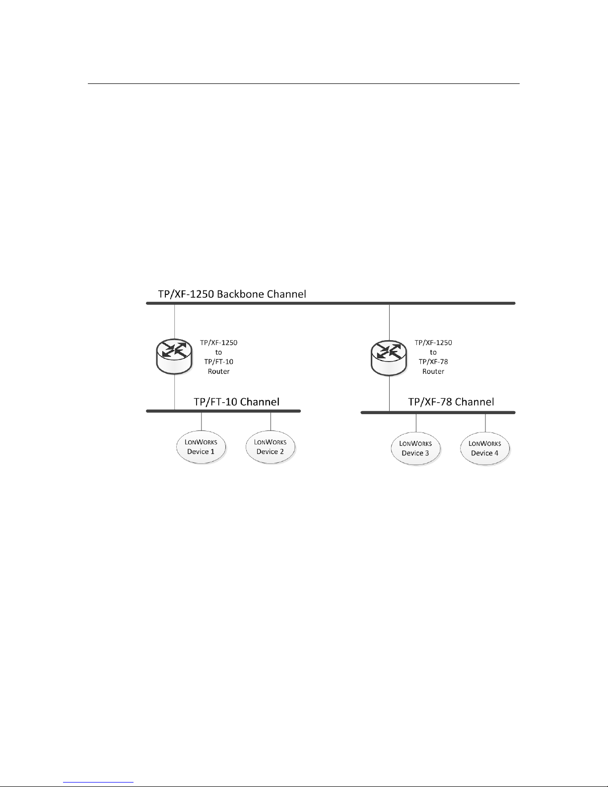
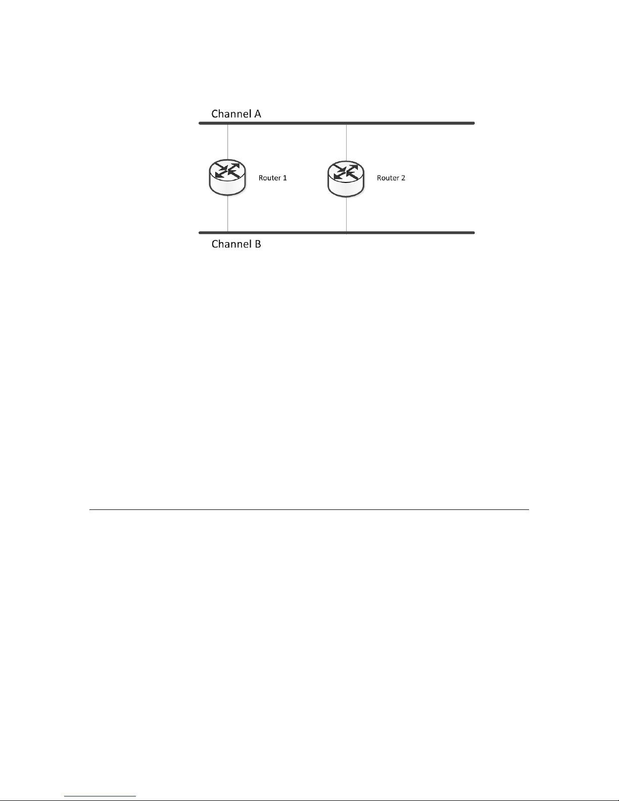
Figure 1 shows a typical router installation, with a free topology channel and a
78 kbps bus topology channel connected to a 1.25 Mbps backbone twisted pair
channel. Because the network includes the routers, applications on each of the
ONWORKS devices can communicate with each other transparently, as if they
L
were installed on a common channel.
ONWORKS
Figure 1. Sample Router Installation
A single router can connect two channels, or multiple routers, called redundant
routers, can connect the same pair of channels. Redundant routers provide fault
tolerance by providing more than one routing path from one channel to another.
They are also required when not all devices on a given channel are able to hear
one another (referred to as an “ear shot problem”), for example on a radio
frequency channel. For a router to function as a redundant router, the router
must be configured to be a Configured router.
ONWORKS routers are used to:
L
• Extend the limits of a single channel. You can use a router to add a
channel to a L
ONWORKS network to support additional devices or to
extend the maximum channel length. You can add multiple routers,
depending on the capacity or distance needed.
• Interface different communications media, or bit rates, in a L
ONWORKS
network. For example, you might want to trade data rate for distance on
portions of the network, or to use a 1.25 Mbps backbone twisted pair
channel to connect several 78 kbps free topology and link power channels.
Alternatively, you might want to use power line for a portion of the
2 Introduction to LonWorks Routers
Page 13

network where the devices are subject to frequent physical relocation, or
if cable installation is difficult. For each of these cases, you use a router
to connect the dissimilar L
ONWORKS channels.
• Enhance the reliability of the L
connect to a router are logically isolated, so a failure on one channel does
not affect the other channel. For example, in an industrial control
network, isolation among connected cells might be desirable to prevent a
failure in a single cell from bringing down multiple cells. You can achieve
this goal by dedicating channels to individual cells and isolating them
from one another with routers.
• Improve overall network performance. You can use routers to isolate
traffic within subsystems. For example, in a cluster of industrial cells,
most of the communications might be between devices within cells rather
than across cells. Using intelligent routers across cells avoids forwarding
messages addressed to devices within a cell, thus increasing the capacity
and decreasing the response time of the overall network.
The use of routers across channels is transparent to the application programs
within devices. Thus, you can develop applications without needing to know the
workings of the routers or even if the device’s channel will use a router. You only
need to consider routers when determining the network image of a device. When
you move a device from one channel to another, you need only change the
network image. Use a network management tool, such as the LonMaker
Integration Tool, to manage network images.
LonWorks Router Products
ONWORKS network. The two channels that
Echelon provides the following router products:
• MPR-50 Multi-Port Router (Model: 42150)
Five-channel (one TP/XF-1250 channel and four TP/FT-10 channels)
ONWORKS router. The MPR-50 can be used to connect two, three, or
L
four TP/FT-10 channels together, or it can be used to connect these
TP/FT-10 channels to a high-speed TP/XF-1250 backbone.
• i.LON 600 L
ONWORKS/IP Server (Model: 7260x)
An EIA-852 compliant LonTalk-to-IP router. The i.LON 600 provides
secure Internet access to L
ONWORKS devices and transforms the Internet
(or other IP-based network) into a pathway for L
information.
• CRD 3000 Power Line/RF Bridge (Model: 76520R)
A Power Line (PL) to RF communications device, designed primarily for
intelligent L
ONWORKS street lighting networks.
• LonPoint Router (Model: 4210x)
A two-channel router for TP/FT-10, TP/XF-78, or TP/XF-1250 L
channels. Six models are available for various network connection
combinations.
ONWORKS control
ONWORKS
LonWorks Router User’s Guide 3
Page 14

• RTR-10 Router Core Module (Model: 61000R)
A compact module used by OEMs to build L
10 consists of the core electronics and firmware needed to implement a
router.
• Router 5000 (Model: 14315R)
A semiconductor product used by OEMs to build half-routers or full
routers for L
required to implement a half-router.
Packaged routers eliminate the need to build hardware and obtain the necessary
electrical interference and safety certifications. Thus, they allow direct, off-theshelf integration into the user’s L
Web page (www.echelon.com/products/routers
packaged Echelon router products.
This manual describes those Echelon router products that allow OEMs to design
and build their own custom routers for L
Core Module and the Router 5000 chips.
RTR-10 Overview
The RTR-10 Router Core Module is a compact module used by OEMs to design
and build L
channels and route LonTalk messages between them. They support installation
of networks with dozens to thousands of devices.
ONWORKS routers. A LONWORKS router connects two communications
ONWORKS routers. The RTR-
ONWORKS channels. The Router 5000 includes the firmware
ONWORKS network. See the Echelon router
) for information about the pre-
ONWORKS channels: the RTR-10 Router
The RTR-10 Module consists of the core electronics and firmware required to
implement a router. Its compact single inline module (SIM) form factor
minimizes the board space required to implement a router. Vertical SIM sockets
are available to minimize board space; right-angle SIM sockets are also available
to minimize component height.
A complete router, using an RTR-10 module, consists of the module, two
transceivers, and a motherboard to connect the RTR-10 router to the two
transceivers, as shown in Figure 2 on page 5.
4 Introduction to LonWorks Routers
Page 15
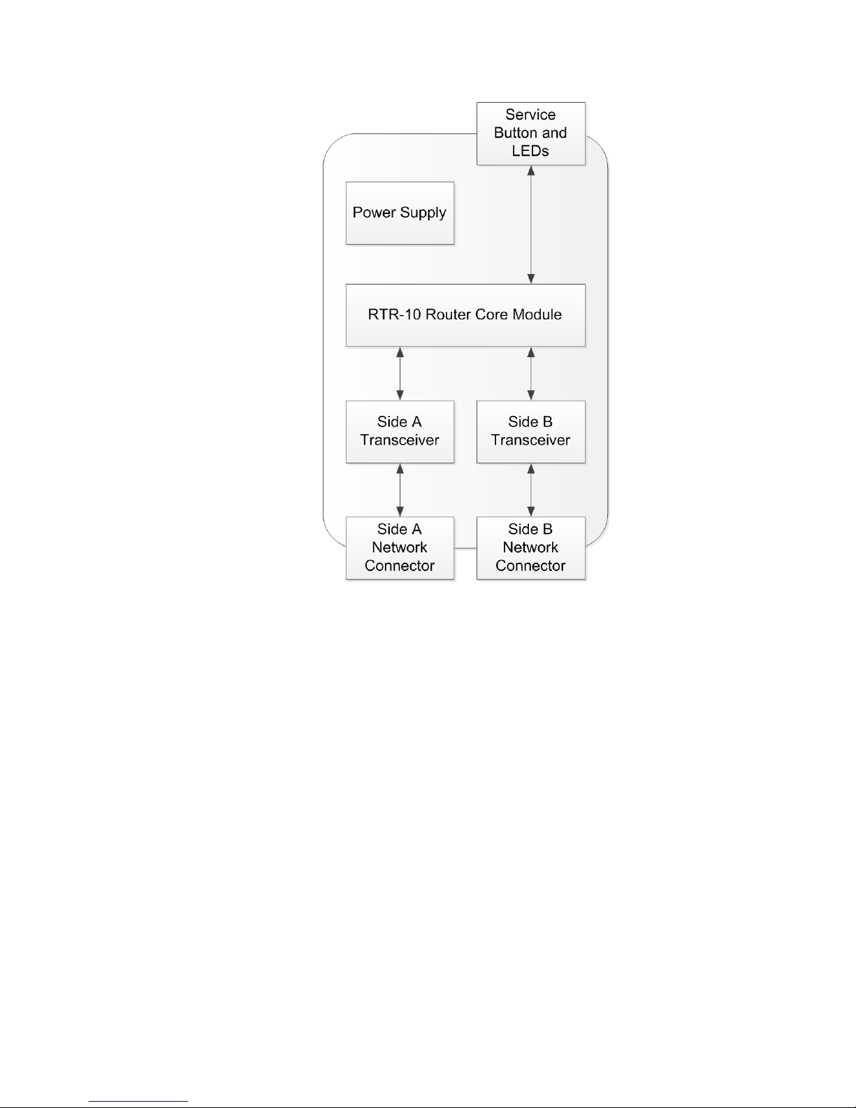
Figure 2. Block Diagram of a LonWorks Router Based on the RTR-10
As the figure shows, an RTR-10 router and two transceiver modules (one to
handle each of two channels connected by the router) can be mounted on a
motherboard, along with a single power supply and two network connectors.
This sub-assembly constitutes a L
ONWORKS router. It can be packaged in an
enclosure to meet unique form factor and environmental requirements.
Depending on the application, the package could contain a single router subassembly, or could include other application-specific hardware. Multiple routers
can be packaged together for some applications, such as a backbone connecting
multiple channels.
The RTR-10 router comes preconfigured with many common L
transceiver parameters. Two sets of five transceiver identification (XID) pins on
the RTR-10 router select the appropriate transceiver type for each side. The
transceiver ID inputs eliminate a manufacturing step by automatically
configuring the RTR-10 router for most transceivers. A special transceiver ID is
reserved for programming any custom type.
One side of the RTR-10 router has a fixed input clock rate of 10 MHz. This side
can be used with transceivers running at interface bit rates from 9.8 kbps to 1.25
Mbps. The second side of the RTR-10 router can be tied to the 10 MHz output of
the first side, requiring no external components for interface bit rates from 9.8
kbps to 1.25 Mbps. Alternatively, the 10 MHz output can be divided to a lower
frequency with external hardware and used as the input clock for the second side
to support transceivers running at bit rates as low as 610 bps.
LonWorks Router User’s Guide 5
ONWORKS
Page 16

Any pair of channel types can be connected by a router by selecting the
appropriate pair of transceivers. The RTR-10 router is compatible with all
ONWORKS transceivers, including standard transceivers for free topology, link
L
power, twisted pair, and power line. Using multiple communications media can
minimize installation costs and increase system performance by allowing easily
installed media, such as power line or link power, to be combined with media
such as TP/XF-1250 twisted pair.
Router 5000 Overview
The Router 5000 chip is an Echelon semiconductor product, based on the Echelon
Neuron 5000 Core, that is used to build half-routers and full routers for
ONWORKS channels. A LONWORKS router connects two communications
L
channels and route LonTalk messages between them. They support installation
of networks with dozens to thousands of devices.
The Router 5000 includes the Router firmware required to implement a halfrouter. The chip’s compact form factor minimizes the space required to develop a
half-router. You can implement two half-routers to develop a full router for the
same, or different, external transceiver types. Table 1 lists commonly used
channel and transceiver types for Router 5000-based router halves. Echelon
provides special licensing for other transceiver types, such as a Power Line Smart
Transceiver. Contact Echelon Support for additional information.
Table 1. Common Channel and Transceiver Types
Channel Type Transceiver for Half Router Notes
TP/FT-10 Echelon FTT-10A Free Topology
Transceiver (Model 50051)
TP-RS485 Any EIA-485 transceiver Can use any standard 3.3V or 5V
TP/XF-78 Echelon TPT Twisted Pair
Transceiver Module (Model
50010)
TP/XF-1250 Echelon TPT Twisted Pair
Transceiver Module (Model
50020)
Link-power Echelon LPT-11 Link Power
Transceiver (Model 50040)
Connection to the Router 5000 is
similar to the connection to a Neuron
Chip (see LonWorks FTT-10A Free
Topology Transceiver User's Guide)
EIA-485 transceiver (see the
Connecting a Neuron 5000 Processor
to an External Transceiver
Engineering Bulletin)
Add differential driver and
differential comparator circuits
(contact Echelon Support)
Add differential driver and
differential comparator circuits (see
the Connecting a Neuron 5000
Processor to an External Transceiver
Engineering Bulletin)
Add linear regulator and TX buffer
circuit (see the Connecting a Neuron
5000 Processor to an External
Transceiver Engineering Bulletin)
6 Introduction to LonWorks Routers
Page 17
These external transceivers can run at interface bit rates from 9.8 kbps to 1.25
Mbps.
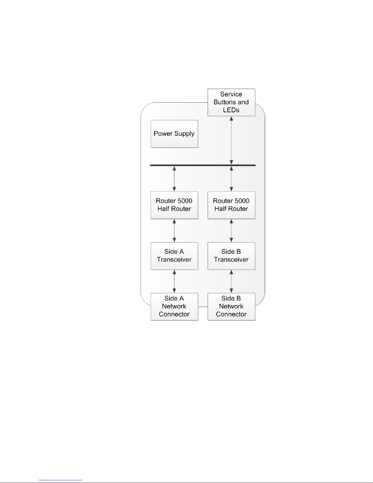
A complete router, using the Router 5000, consists of two Router 5000 half
routers, two transceivers, and a motherboard to connect the two half routers, as
shown in Figure 3.
Figure 3. Block Diagram of a LonWorks Router Based on the Router 5000
As the figure shows, two Router 5000 half routers and two transceiver modules,
one to handle each of two channels connected by the router, can be mounted on a
motherboard, along with a single power supply and two network connectors.
This sub-assembly constitutes a L
enclosure to meet unique form factor and environmental requirements.
Depending on the application, the package could contain a single router subassembly, or could include other application-specific hardware. Multiple routers
can be packaged together for some applications, such as a backbone connecting
multiple channels.
Unlike an RTR-10 router, you store the L
each Router 5000 half router in external EEPROM, thus allowing you to define
the appropriate transceiver type for each side.
LonWorks Router User’s Guide 7
ONWORKS router. It can be packaged in an
ONWORKS transceiver parameters for
Page 18

Router Types
A LONWORKS router can use one of four routing algorithms: configured router,
learning router, bridge, and repeater. This selection allows you to trade system
performance for ease of installation. The configured router and learning router
algorithms create intelligent routers that selectively forward messages based on
network topology. Both sides of a router must use the same routing algorithm.
The following general rules apply to all four routing algorithms:
• For a message to be forwarded, it must fit into the router’s input and
output message buffers. A free input message buffer must be available.
• For a message to be forwarded, it must have a valid cyclic redundancy
check (CRC) code.
• Priority messages are forwarded as priority messages, but with the
priority level of the transmitting side rather than the priority level of the
originator of the message. If the transmitting side has not been installed
with a priority value, then priority messages are not forwarded in a
priority slot. The priority message is still flagged as a priority message,
so that if it passes through a second router that is installed with a
priority level, the second router transmits the message in a priority slot.
Repeater
A Repeater is a router that forwards all messages in both directions, regardless of
the message’s destination or domain. That is, a repeater forwards all valid
messages (that is, messages with a valid CRC code) to the other channel.
A Permanent Repeater behaves similarly, but its type cannot be changed after
creation.
Bridge
A Bridge is a router that forwards all messages received on either of the router’s
domains, regardless of the message’s destination. That is, a bridge forwards
packets received on one channel to the other channel, if the packet is sent on a
domain to which the bridge belongs. Use a bridge to span domains. In a single
domain network, a bridge functions essentially the same as a repeater.
A Permanent Bridge behaves similarly, but its type cannot be changed after
creation.
Configured Router
A Configured Router determines which packets to forward based on internal
routing tables. A configured router forwards only those messages which are
received on either of the router’s domains and which meet the forwarding rules
shown in Figure 4 on page 10 and Figure 5 on page 11. Configured routers
maintain their routing tables in non-volatile memory, and thus retain them after
a reset. These tables control forwarding of subnet and group-addressed
messages, and are managed by a network management tool.
8 Introduction to LonWorks Routers
Page 19

A forwarding table is used for each domain on each side of the router. Each
forwarding table contains a forwarding flag for each of the 255 subnets and 255
groups in a domain. As shown in Figure 4 and Figure 5, these flags determine
whether or not a message should be forwarded or dropped based on the
destination subnet or group address of the message.
A network management tool initializes the forwarding tables using the network
management messages described in Chapter 7, Network Management Messages,
on page 71. By configuring the routing tables based on network topology, a
network management tool can optimize network performance and make the most
efficient use of available bandwidth. Configured routers should be used for
looping topologies; see Loop Topology on page 11.
For a L
volatile memory (typically EEPROM) and one in RAM. The non-volatile table is
copied to the RAM table when the router is initially powered-up, after a reset,
and when the router receives the Set Router Mode command with the Initialize
Routing Table option. The RAM table is used for all forwarding decisions.
Several of the operations in shown in Figure 4 and Figure 5 help prevent
message loops for service-pin messages. Service-pin messages require special
handling because they are broadcast to all nodes on the zero-length domain, and
have a source subnet ID of zero. When a router receives a service-pin message
with a source subnet ID of zero, the router modifies the source subnet field of the
message to be the router’s subnet on the receiving side. If the receiving side is
installed in two domains, two service-pin messages are forwarded, one for each
domain. Thus, the router can drop the service-pin message if a loop causes the
message to be received again on the same side.
ONWORKS router, there are two sets of forwarding tables, one in non-
Learning Router
A Learning Router, like a configured router, determines which packets to forward
based on internal routing tables. A learning router forwards only those messages
which are received on either of the router’s domains and which meet the
forwarding rules shown in Figure 4 on page 10 and Figure 5 on page 11. A
learning router always forwards all group-addressed messages. Learning routers
maintain their routing tables in non-volatile memory, and thus retain them after
a reset. These tables control forwarding of subnet and group-addressed
messages, and are updated automatically by the router firmware, rather than
their being configured by a network management tool. The group forwarding
tables are configured to always forward (flood) all messages with group
destination addresses.
When a router receives a packet with a destination address using a subnet ID, it
uses the subnet ID to determine whether to forward the packet. Learning
routers learn network topology by examining the source subnet of all messages
received by the router. Whenever a learning router receives a packet from one of
its channels, it uses the source subnet ID to learn the network topology. It sets
the corresponding routing table entries to indicate that the subnet in question is
to be found in the direction from which the packet was received. Because subnets
cannot span two channels connected to an intelligent router, the router can learn
which side a subnet is on whenever that subnet ID appears in the source address.
The subnet forwarding tables are initially configured to forward all messages
with subnet destination addresses. Each time a new subnet ID is observed in the
source address field of a message, its corresponding flag is cleared (that is,
LonWorks Router User’s Guide 9
Page 20

forwarding is disabled) in the subnet forwarding table. The forwarding flag for
the destination address is then checked to determine whether the message
should be forwarded or dropped. The forwarding flags are all cleared whenever
the router is reset, so the learning process restarts after a reset.
The forwarding flag for a given subnet should never be cleared on both sides of a
router. However, the flag can be cleared on both sides if a device is moved from
one side of a router to the other side. For example, if subnet 1 is located on side
A of a router, the router will learn subnet 1’s location as soon as it receives a
message generated by any device in subnet 1. If any subnet 1 device is moved to
side B without reinstalling it, the router will learn that subnet 1 is also on side B,
and will stop forwarding subnet 1 messages to side A. The router detects this
error and logs it, as described in Chapter 7, Network Management Messages, on
page 71.
Figure 4. Configured and Learning Router Forwarding Rules, Part 1
10 Introduction to LonWorks Routers
Page 21
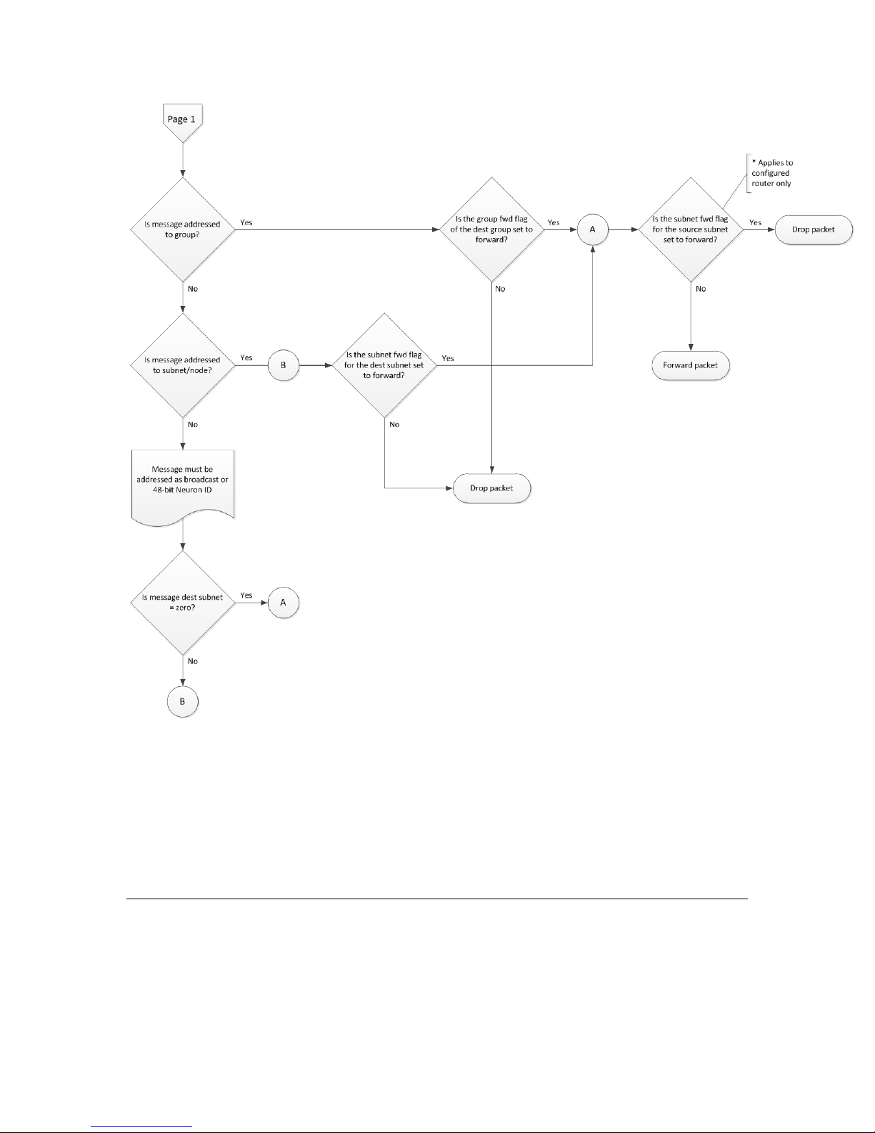
Figure 5. Configured and Learning Router Forwarding Rules, Part 2
As with configured routers, learning routers sometimes modify source addresses
for service-pin messages to help prevent message loops.
Learning routers, in general, are less efficient in using channel bandwidth
because they always forward all messages with group destination addresses.
Their advantage is simplified installation because the installation tool does not
need to know the network topology to configure the router.
Loop Topology
A looping topology is a network topology that has the potential for message loops.
A loop is a path through two or more routers that forwards a message from a
channel to itself. For example, Figure 6 on page 12 shows a looping topology
with two channels and two routers. A message on channel A could be forwarded
LonWorks Router User’s Guide 11
Page 22
by router 1 to channel B, then the same message could be forwarded by router 2
back to channel A, starting an endless loop of forwarded messages.
Figure 6. Looping Topology
The LonTalk protocol does not support topologies where loops can occur.
However, looping topologies can be desirable for the following reasons:
• Increased Reliability. Redundant routers can increase system reliability
by providing multiple paths between two channels.
• Support for Open Media. Open media (such as radio frequency [RF]
communications) might require redundant routers with overlapping
coverage to ensure complete coverage of an area.
You can use configured routers (see Configured Router on page 8) to support
looping topologies by configuring the routers to prevent message loops. For
example, the topology in Figure 6 can be supported if both routers are
configured to forward all messages addressed to subnets on channel B from
channel A; and all messages addressed to subnets on channel A from channel B.
Any groups with members on both channels can only be forwarded by one of the
two routers.
Network management tools, such as the LonMaker Integration Tool, can
automatically set up the forwarding tables for configured redundant routers.
Power Line Routers
A looping topology can be inadvertently created when using power line (PL)
media. Passive coupling between different phases of a power line system can
cause packets transmitted on one phase to be received by devices installed on
another phase. A loop can be formed when active coupling provided by a router is
combined with passive coupling. Figure 7 on page 13 shows an example looping
topology with a power line router.
12 Introduction to LonWorks Routers
Page 23

Figure 7. A Looping Topology with One Router
Routers can be used between power line channels only if the two channels are
fully isolated. Such isolation is generally not the case between two phases on the
same circuit, but can be the case between phases on different distribution
transformers. Use Echelon’s PLCA-10, PLCA-20, or PLCA-30 Power Line
Communication Analyzers to confirm isolation between power line channels
before installing power-line-to-power-line routers.
LonTalk Protocol Support for Routers
The LonTalk protocol1 is designed to provide transparent routing of messages
between devices that communicate through routers. To increase the efficiency of
routers, the LonTalk protocol defines a hierarchical form of addressing using
domain, subnet, and device (node) addresses. An intelligent router operates at
the subnet level. The router determines which subnets lie on each of its two
sides, and forwards packets accordingly.
Subnets do not span intelligent routers, which allows intelligent routers to make
routing decisions based on the subnet component of a device’s logical address. To
further facilitate the addressing of multiple dispersed devices, the LonTalk
protocol defines another class of addresses using domain and group addresses.
Intelligent routers also can be configured to make routing decisions based on the
group addressing component of a message.
In general, a network management tool, such as the LonMaker Integration Tool,
is responsible for domain, subnet, node, and group address assignments.
See the ISO/IEC 14908 Control Network Protocol specification for detailed
information about the LonTalk protocol.
Message Buffers
As messages are received by a router, they are placed in an input buffer queue.
By default, this queue is limited to two message buffers to ensure that priority
messages are never enqueued behind more than one non-priority message. When
1
Echelon’s implementation of the ISO/IEC 14908 Control Network Protocol is called the
LonTalk protocol. Echelon has implementations of the LonTalk protocol in several product
offerings, including the Neuron firmware, LNS Server, SmartServers, and various network
interfaces. This document refers to the ISO/IEC 14908-1 Control Network Protocol as the
“LonTalk protocol”, although other interoperable implementations exist.
LonWorks Router User’s Guide 13
Page 24

forwarded to the transmitting side of the router, priority messages have their
own outgoing buffer queue. Thus, priority processing of these outgoing messages
is assured because the transmitting side will send messages from the priority
output buffer queue before sending messages from the non-priority output buffer
queue. Figure 8 shows the message flow through the input and output buffer
queues. This message flow is duplicated for messages moving in the opposite
direction, that is, another set of input and output buffer queues exist for
messages flowing in the opposite direction.
Figure 8. Buffering Scheme for a LonWorks Router
The size and count of the message buffers is limited by the amount of RAM on
the router.
RTR-10 Message Buffers
Each router side has 1254 bytes of buffer space available. By default, this space
is allocated as two input buffers, two priority output buffers, and 15 non-priority
buffers. The default buffers are all 66 bytes in size. Table 2 shows the default
buffer configuration.
Table 2. Default RTR-10 Buffer Configuration
Queue Count
Input Buffer Queue 2 66 132
Priority Output Buffer Queue 2 66 132
Non-Priority Output Buffer Queue 15 66 990
Total 1254
The default buffer size of 66 bytes allows the router to handle packets with
maximum address overhead and data size for any network variable message and
explicit messages with up to 40 bytes of data; this size is large enough for any
network management or network diagnostic message. In applications that must
route large explicit messages with more than 40 bytes of data, the buffer size
Size
(Bytes) Total Bytes
14 Introduction to LonWorks Routers
Page 25

must be increased, and the count of nonpriority buffers decreased. See Chapter 8
of the Neuron C Programmer’s Guide to understand how the network buffer sizes
are calculated. See Chapter 7, Network Management Messages, on page 71, for a
description of how to change the size and count of buffers. You can also use the
NodeUtil Node Utility, which you can download from the Echelon Web site.
However you allocate the buffer sizes and counts, the total memory required by
the three buffer queues must not exceed 1254 bytes.
The default buffer configuration places the bulk of the buffers on the output
queues of the router. For example, the standard configuration places two
network buffers on the input queue and 17 buffers on the output queue (2 priority
and 15 non-priority) of each router side. The reasoning behind this configuration
is to keep buffered packets on the output queues, after they have been processed
for forwarding. This processing includes checking for priority packets. Priority
packets are sensed and forwarded through the router’s priority output buffers, so
that priority packets are processed as quickly as possible, rather than allowing
them to be delayed behind non-priority packages in a large input queue.
There are applications, however, where the network traffic can be “bursty”,
where many packets appear on the network almost at the same time. In these
cases, the traffic bursts could cause the input queue to become full and lose
excess packets.
In this case, it might be preferable to move more of the packet buffering from the
output queue to the input queue by increasing the size of the input queue and
decreasing the size of the output queue. A router with a larger input queue can
handle larger bursts of traffic, at the risk of priority messages’ being queued
behind a number of non-priority messages.
Router 5000 Message Buffers
Each router side has maximum 26 623 bytes of buffer space available. Because
the Router 5000 has sufficient RAM available for any router configuration, you
can allocate this space with any combination of buffers, for example, seven input
buffers, two priority output buffers, and seven non-priority buffers. You can
specify any valid buffer size (see Chapter 8 of the Neuron C Programmer’s Guide
for information about valid buffer sizes), but, in general, there is no reason not to
specify the maximum size of 255 bytes. Table 3 shows a general buffer
configuration.
Table 3. General Router 5000 Buffer Configuration
Queue Count
Input Buffer Queue 7 255 1785
Priority Output Buffer Queue 2 255 510
Non-Priority Output Buffer Queue 7 255 1785
Total 4080
The buffer size of 255 bytes allows the router to handle packets with maximum
address overhead and data size for any network variable message or explicit
Size
(Bytes) Total Bytes
LonWorks Router User’s Guide 15
Page 26

message. See Configuring a Router 5000 Half-Router on page 53 and the
example Neuron C code in Example Neuron C Source on page 56, for a
description of how to change the size and count of buffers. You can also use the
NodeUtil Node Utility, which you can download from the Echelon Web site.
However you allocate the buffer sizes and counts, the total memory required by
the three buffer queues must not exceed 25 K bytes.
The general buffer configuration shown in Table 3 balances the buffers between
the input and output queues of the router. For systems with large bursts of
traffic, you could specify additional non-priority output buffers. Priority packets
are sensed and forwarded through the router’s priority output buffers, so that
priority packets are processed as quickly as possible, rather than allowing them
to be delayed behind non-priority packages in a large input queue.
Router Performance
A major criterion of router performance is network throughput. An optimal
router would be able to forward traffic at the wire-rate, with zero packet loss and
minimal delay. Thus, an optimal router would forward traffic from 9.8 kbps to
1.25 Mbps, depending on the router’s transceiver type.
A real router typically does not perform at the wire-rate because of latency within
the router, including the time to receive and buffer the incoming packet at the
near side, the time to forward the packet between the halves, and the time to
buffer and transmit the packet at the far side. You should measure your router
device’s latency to determine if its design meets your system’s needs.
Example: For a 20 MHz Router 5000 device (where both halves use the Router
5000 chip), a measured data transfer rate for sending a service-pin message
between the router halves was approximately 1.2 μs per byte (or 830 kbytes/sec).
Some additional latency was also seen for the time between the beginning of the
original packet transmission and the beginning of the forwarded packet
transmission.
For slower channel types, this router latency is not significant, but could become
significant for faster channel types.
The latency between router halves is relatively invariant, with respect to router
configuration, whereas overall router latency depends on the router type and
configuration. For an RTR-10 device, the maximum data transfer rate between
router halves is approximately 2.4 μs per byte (or 416 kbytes/sec). For a Router
5000 device (where both halves use the Router 5000 chip), the maximum data
transfer rate between router halves is approximately 300 ns per byte (or 3.3
Mbytes/sec, assuming an 80 MHz system clock for both halves; this rate scales
with the system clock setting).
16 Introduction to LonWorks Routers
Page 27

2
LonWorks Router Electrical
Interfaces
This chapter provides an overview of the electrical interfaces for the
RTR-10 Router Core Module and the Router 5000 chip.
LonWorks Router User’s Guide 17
Page 28
Overview
This chapter describes the electrical interface and power requirements for a
ONWORKS router.
L
Electrical Interface
The following sections describe the electrical interface for a LONWORKS router,
including detailed descriptions of each of the RTR-10 and Router 5000 pins.
RTR-10 Electrical Interface
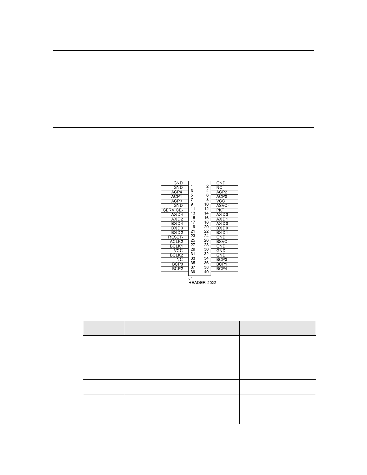
Figure 9 shows a schematic view of a connector for the RTR-10 Router Core
Module, and Table 4 shows the pinout of the RTR-10 Router Core Module. See
the Neuron Chip Data Book for more information about the use of the Neuron
Chip communications port pins.
Figure 9. RTR-10 Header Pinout
Table 4. RTR-10 Pinout
Pin Name Pin Description Pin Number
ACLK2 A-side output clock 27
ACP0 A-side network communication port 0 8
ACP1 A-side network communication port 1 7
ACP2 A-side network communication port 2 6
ACP3 A-side network communication port 3 9
ACP4 A-side network communication port 4 5
18 LonWorks Router Electrical Interfaces
Page 29

Pin Name Pin Description Pin Number
ASVC~ A-side Service output 12
AXID0 A-side transceiver ID 0 (LSB) 20
AXID1 A-side transceiver ID 1 18
AXID2 A-side transceiver ID 2 17
AXID3 A-side transceiver ID 3 16
AXID4 A-side transceiver ID 4 (MSB) 15
BCLK1 B-side input clock 29
BCLK2 B-side output clock 33
BCP0 B-side network communication port 0 37
BCP1 B-side network communication port 1 38
BCP2 B-side network communication port 2 39
BCP3 B-side network communication port 3 36
BCP4 B-side network communication port 4 40
BXID0 B-side transceiver ID 0 (LSB) 22
BXID1 B-side transceiver ID 1 24
BXID2 B-side transceiver ID 2 23
BXID3 B-side transceiver ID 3 21
BXID4 B-side transceiver ID 4 (MSB) 19
BSVC~ B-side Service output 28
GND Ground 1, 2, 3, 11, 26, 30, 32, 34
PKT Packet forward output 14
RESET~ Reset input and output) 25
SERVICE~ Combined Service input 13
VCC +5 VDC input 10, 31
NC No Connect 4, 35
LonWorks Router User’s Guide 19
Page 30

ACLK2, BCLK1, and BCLK2
A 10 MHz crystal is provided for Side A of the RTR-10 router, which can run at
only 10 MHz. This clock rate allows Side A to be used with transceivers running
at interface bit rates from 9.8 kbps to 1.25 Mbps. The 10 MHz clock is output on
the ACLK2 pin, which allows Side B to be tied directly to the same clock through
pin BCLK1. Thus, no external components are required to support the same
range of bit rates on Side B.
The 10 MHz output can be divided to a lower frequency with external hardware,
and used as the input clock for Side B to support transceivers running at
interface bit rates as low as 610 bps.
ACLK2 can drive five LS-TTL loads.
ACP[4..0] and BCP[4..0]
The ACP[4..0] and BCP[4..0] signals are connected to the CP[4..0] pins of the
core module Neuron Chips. The function of these pins is described in the Neuron
Chip Data Book.
ASVC~ and BSVC~
Each side of the RTR-10 router has an independent service-pin output: ASVC~
for the A Side and BSVC~ for the B Side. You can connect these output pins to
service LEDs, as shown in Figure 23 on page 47 (in chapter 4). The function of
the service pin is described in the Neuron Chip Data Book. The internal pullup
resistor for the service pin on each side is enabled.
The service LEDs reflect the firmware status:
• Blinking means that the router side is unconfigured
• Off means that the side is configured
• On means that the side has failed
AXID[4..0] and BXID[4..0]
The RTR-10 router comes preconfigured with many common LONWORKS
transceiver parameters. Two sets of five transceiver identification (ID) pins on
the RTR-10 router select the appropriate transceiver type for each side. The
transceiver ID inputs eliminate a manufacturing step by automatically
configuring the RTR-10 router for most transceivers. A special transceiver ID is
reserved for programming any custom transceiver type; this value causes the
communication port pins to be configured as inputs so that no line will be driven
by both the transceiver and RTR-10 Neuron before the RTR-10 Neuron Chips can
be properly configured.
The RTR-10 firmware reads the transceiver ID inputs on power up and reset. If
the router is being powered-up for the first time, or if the transceiver ID is
different from the last time it was powered-up, the parameters specified in Table
5 on page 21 are loaded. If the router is being re-powered-up, and the transceiver
ID is not 30 (0x1E), the RTR-10 firmware compares the network bit rate and
input clock for the specified transceiver to the current transceiver parameters. If
these parameters do not match, all transceiver parameters are reinitialized. This
20 LonWorks Router Electrical Interfaces
Page 31

reinitialization allows a network services tool to change parameters, such as the
number of priority slots, without the new values’ being overwritten by the RTR10 firmware.
Table 5. RTR-10 Router Transceiver IDs
ID Name Media
Bit Rate
(bps)
Input
Clock
01 (0x01) TP/XF-78 Transformer-isolated twisted pair 78k 10 MHz
03 (0x03) TP/XF-1250 Transformer-isolated twisted pair 1.25M 10 MHz
04 (0x04) TP/FT-10 Free Topology and Link Power 78k 10 MHz
05 (0x05) TP/RS485-39 EIA-485 twisted pair 39k 10 MHz
07 (0x07) RF-10 Radio Frequency (49 MHz) 4.9k 5 MHz
09 (0x09) PL-10 Power Line spread-spectrum 10k 10 MHz
10 (0x0A) TP/RS485-625 EIA-485 twisted pair 625k 10 MHz
11 (0x0B) TP/RS485-125 EIA-485 twisted pair 1.25M 10 MHz
12 (0x0C) TP/RS485-78 EIA-485 twisted pair 78k 10 MHz
16 (0x10) PL-20C Power Line C-Band 5.4k 10 MHz
17 (0x11) PL-20N Power Line C-Band 5.4k 10 MHz
18 (0x12) PL-30 Power Line A-Band 2.7k 10 MHz
24 (0x18) FO-10 Direct Connect 1.25M 10 MHz
27 (0x1B) DC-78 Direct Connect 78k 10 MHz
28 (0x1C) DC-625 Direct Connect 625k 10 MHz
29 (0x1D) DC-1250 Direct Connect 1.25M 10 MHz
30 (0x1E) Custom Custom Custom Custom
Notes:
• Type 07 (0x07) can be used for Side B only.
• PL-20C channels use the CENELEC protocol; PL-20N channels do not use the
CENELEC protocol.
• Type 30 (0x1E) can be used for any transceiver type; the communications port is
initially defined as all inputs to prevent circuit conflicts. The side using type 30
(0x1E) must be reprogrammed through the other router side.
LonWorks Router User’s Guide 21
Page 32

See Appendix A, Communications Parameters for LonWorks Routers, on page 81,
for a listing of the communications parameters for each transceiver type.
PKT
The PKT output can be used as a network activity indicator. When packets are
passed between the router sides, PKT is active. This signal uses the unbuffered
IO0 signal from the Neuron Chips. You can add a pulse stretcher circuit driven
by PKT to make an activity LED flash, as in the example circuit shown in
Figure 23 on page 47 (in chapter 4).
RESET~
The Neuron Chip reset pins are tied together and brought out on one pin.
Figure 10 shows the reset circuitry on the RTR-10 router.
Typical applications do not require debounce conditioning of a momentary
pushbutton attached to the RESET~ pin. The software response time associated
with this input is long enough to effectively provide a software debounce for
switches with a contact bounce settling time as long as 20 milliseconds. The
22 LonWorks Router Electrical Interfaces
Figure 10. RTR-10 Reset Circuit
Page 33

RESET~ signal must be driven low by a low voltage protection circuit on the
SVC~
IO0
IO1
IO2
IO3
VDD1V8
IO4
VDD3V3
IO5
IO6
IO7
IO8 VDDPLL
GNDPLL
VOUT1V8
RST~
VIN3V3
VDD3V3
AVDD3V3
CP0
AGND
CP1
NC
GND
IO9
IO10
IO11
VDD1V8
TRST~
VDD3V3
TCK
TMS
TDI
TDO
XIN
XOUT
CP2
CP3
CP4
CS0~
VDD3V3
VDD3V3
SDA_CS1~
VDD1V8
SCL
MISO
SCK
MOSI
37
38
39
40
41
42
43
44
45
46
47
48
1
2
3
4
5
6
7
8
9
10
11
12
13
14
15
16
17
18
19
20
21
22
23
24
25
26
27
28
29
30
31
32
33
34
35
36
GND PAD
Router 5000
®
router motherboard as described in Low Voltage Protection on page 37.
SERVICE~
The SERVICE~ input drives both sides of the RTR-10 router from a single input.
You can connect a pushbutton to this pin broadcast each side’s 48-bit Neuron ID
on its channel (for example, during installation).
Typical applications do not require debounce conditioning of a momentary
pushbutton attached to the SERVICE~ pin. The software response time
associated with this input is long enough to effectively provide a software
debounce for switches with a contact bounce settling time as long as 20
milliseconds.
Router 5000 Electrical Interface
The electrical interface for the Router 5000 chip is similar to the electrical
interface of the Neuron 5000 Processor, described in the Series 5000 Chip Data
Book. Figure 11 shows the pinout for the Router 5000 chip. The central
rectangle in the figure represents the bottom pad (pin 49), which must be
connected to ground.
LonWorks Router User’s Guide 23
Figure 11. Router 5000 Chip Pinout
Page 34

Table 6 lists the pin assignments for the Router 5000 chip. All digital inputs are low-voltage
SVC~
1
Digital I/O
Service (active low)
VDD3V3
18
Power
3.3 V Power
TMS
20
Digital Input
JTAG Test Mode Select
TDO
22
Digital Output
JTAG Test Data Out
transistor-transistor logic (LVTTL) compatible, 5 V tolerant, with low leakage. All digital
outputs are slew-rate limited to reduce Electromagnetic Interference (EMI) concerns.
Table 6. Router 5000 Chip Pin Assignments
Pin
Name
Number Type Description
IO0 2 Digital I/O IO0 (side A to side B)
IO1 3 Digital I/O IO1 (side A to side B)
IO2 4 Digital I/O IO2 (side A to side B)
IO3 5 Digital I/O IO3 (side A to side B)
VDD1V8 6 Power 1.8 V Power Input
(from internal voltage regulator)
IO4 7 Digital I/O IO4 (side A to side B)
VDD3V3 8 Power 3.3 V Power
IO5 9 Digital I/O IO5 (side A to side B)
IO6 10 Digital I/O IO6 (side A to side B)
IO7 11 Digital I/O IO7 (side A to side B)
IO8 12 Digital I/O IO8 (side A to side B)
IO9 13 Digital I/O IO9 (side A to side B)
IO10 14 Digital I/O IO10 (side A to side B)
IO11 15 Digital I/O IO11 (not used for routers)
VDD1V8 16 Power 1.8 V Power Input
(from internal voltage regulator)
TRST~ 17 Digital Input JTAG Test Reset (active low)
TCK 19 Digital Input JTAG Test Clock
TDI 21 Digital Input JTAG Test Data In
XIN 23 Oscillator In Crystal oscillator input
XOUT 24 Oscillator Out Crystal oscillator output
VDDPLL 25 Power 1.8 V Power Input
(from internal voltage regulator)
GNDPLL 26 Power Ground
VOUT1V8 27 Power 1.8 V Power Output
24 LonWorks Router Electrical Interfaces
(of internal voltage regulator)
Page 35

Pin
RST~
28
Digital I/O
Reset (active low)
VDD3V3
30
Power
3.3 V Power
CP0
32
Comm
CP0: Receive serial data
SCK
47
Digital I/O for
SPI serial clock
PAD
49
Ground Pad
Ground
Name
VIN3V3 29 Power 3.3 V Power Input
AVDD3V3 31 Power 3.3 V Power
AGND 33 Ground Ground
CP1 34 Comm CP1: Transmit serial data
NC 35 N/A Do Not Connect
GND 36 Ground Ground
CP2 37 Comm CP2: External transceiver enable output
CP3 38 Comm CP3: Do Not Connect
CP4 39 Comm CP4: Collision detect input
Number Type Description
CS0~ 40 Digital I/O for
Memory
VDD3V3 41 Power 3.3 V Power
VDD3V3 42 Power 3.3 V Power
SDA_CS1~ 43 Digital I/O for
Memory
VDD1V8 44 Power 1.8 V Power Input
SCL 45 Digital I/O for
Memory
MISO 46 Digital I/O for
Memory
Memory
MOSI 48 Digital I/O for
Memory
SPI slave select 0 (active low)
I2C: serial data
SPI: slave select 1 (active low)
(from internal voltage regulator)
I2C serial clock
SPI master input, slave output (MISO)
SPI master output, slave input (MOSI)
Clock Pins (XIN and XOUT)
The Router 5000 chip requires a 10 MHz external crystal or oscillator to provide
its input clock signal. The chip then multiplies the input frequency by an amount
specified in the device’s hardware template (specified during device development
using the NodeBuilder FX Development Tool; see NodeBuilder Hardware
Template on page 53) to derive its internal system clock frequency. For
LonWorks Router User’s Guide 25
Page 36

multipliers greater than one, the chip uses a phase-locked loop (PLL) to drive and
manage the internal on-chip system clock frequency.
A Router 5000 chip requires a 10.0 MHz external clock signal for operation. An
example part that meets the requirements for a Router 5000 chip is the Abracon
Corporation ABMM2-100000MHz-D1 Ceramic Surface Mount Low Profile Quartz
Crystal.
The crystal must have a load capacitance rating of 18 pF. The internal
capacitance for the XIN and XOUT pins is approximately 4.5 pF. To maintain
the crystal’s load capacitance, add a pair of 33 pF external capacitors, as shown
in Figure 12. Note that Figure 12 applies to a single Router 5000 half-router.
Also, you must consider trace capacitance when calculating the values of the
external capacitors. In the figure, the values for R1 (feedback resistor) and R2
(damping resistor) apply to any crystal used.
Figure 12. Series 5000 Chip Clock Generator Circuit
To ensure proper oscillator startup, the equivalent series resistance specification
for the crystal should be ≤50 Ω, and the crystal shunt capacitance should be no
greater than 7 pF.
Using a 33 pF capacitor for C2 (in Figure 12), the Router 5000 chip’s XOUT pin
cannot be used to drive an external CMOS load. However, if you maintain the
required capacitance for the XOUT pin, you can drive an external clock, for
example, for another Router 5000 half-router.
If your Router 5000 device requires a common clock signal for both router halves,
you can adjust the value for C2 (in Figure 12), add a buffer, and leave the B Side
XOUT unconnected, as shown in Figure 13 on page 27. Clock traces should be
kept short (≤2 cm, ≤0.8 inch). Keep the crystal circuit close to the Router 5000
chips and isolated from communications lines. In addition, a logic ground guard
must be added for the clock trace to minimize clock noise and to help keep EMI
levels low. However, this ground guard should not be used as a ground source for
digital circuitry.
In addition, the connection between A Side XOUT pin and the B Side XIN pin
includes standard (inverting or non-inverting) bus buffer/line driver.
26 LonWorks Router Electrical Interfaces
Page 37

Important: Because the Router 5000 A Side XOUT pin drives an input buffer,
the values of the external capacitors are not equal. The value for A Side XOUT
is specified as 30 pF based on an internal input capacitance of 4.5 pF of the
XIN/XOUT pins and internal input capacitance for the buffer/line driver of 3 pF
at 25 ºC (so that the total capacitance for the A Side XOUT pin is 33 pF). For
some bus buffer/line drivers, input capacitance can vary over temperature, up to
10 pF. If your device is likely to experience extreme temperatures, consider
changing the value for the A Side XOUT capacitor to 27 pF to allow for the
change in capacitance over temperature.
See the Series 5000 Chip Data Book for more information about the clock
requirements for a Series 5000 chip, including the Router 5000.
CP[4..0]
The Router 5000 has a very versatile communications port, the CP[4..0] pins (32,
34, 37, 38, and 39). It consists of five pins that can be configured to interface to a
wide variety of media interfaces (network transceivers) and operates over a wide
range of data rates.
LonWorks Router User’s Guide 27
Figure 13. Common Clock Connections
Page 38

The communications port for the Router 5000 is configured to operate in singleended mode. Table 7 lists the pin assignments for the communications port
pins.
Table 7. Communications Port Pin Assignments
Single-Ended
Pin Drive Current
CP0 N/A Data input Transceiver RXD
CP1 8 mA Data output Transceiver TXD
Mode (3.3 V) Connect To
CP2 8 mA Transmit Enable
output
CP3 N/A Do Not Connect
CP4 8 mA Collision Detect
input
Before programming, a Router 5000 uses its default communications parameters,
which define a simplified single-ended mode 78 kbps channel. The default
communications parameters allow you to load an application image over a 78
kbps network, for example during device manufacturing. Devices that use a 78
kbps transceiver (such as a 78 kbps EIA-485 transceiver or an LPT-11 Link
Power Transceiver) can use the default communications parameters within
development or manufacturing test networks. For production networks
(networks with many devices), you should ensure that each device has
communications parameters defined for the channel; see Appendix A,
Communications Parameters for LonWorks Routers, on page 81.
Note that devices defined for a TP/XF-1250 channel cannot use the default
communications parameters; each device’s external serial non-volatile memory
must be loaded with the correct communications parameters before connecting to
the network.
See the Series 5000 Chip Data Book for more information about the
communications port for the Neuron 5000 Processor, which is functionally
equivalent to the Router 5000 communications port.
Transmit Enable
(single ended mode)
Collision Detect
(single ended mode)
IO[11..0]
These digital I/O pins provide the communications between the A side and B side
of a Router 5000 device. Connect the IO pins for one router side to the
corresponding IO pin on the other router side, as shown in Figure 14 on page 29.
Note that you must provide 10 kΩ pull-up resistors for the IO6, IO7, and IO10
pins. The IO11 pin is not used for either router half, but it should be pulled up
with a 10 kΩ pull-up resistor.
28 LonWorks Router Electrical Interfaces
Page 39

Figure 14. Digital IO Pin Connections
Important: When routing the IO[11..0] signals between the two router halves
of your Router 5000 device, keep the traces as short as possible.
See the Series 5000 Chip Data Book for more information about the digital I/O
pins for a Series 5000 chip, including the Router 5000.
JTAG Interface (TCK, TDI, TDO, TMS, and
TRST~)
All Series 5000 chips (including the Router 5000) provide an interface for the
Institute of Electrical and Electronics Engineers (IEEE) Standard Test Access
Port and Boundary-Scan Architecture (IEEE 1149.1-1990) of the Joint Test
Action Group (JTAG) to allow a Series 5000 chip to be included in the boundaryscan chain for device production tests.
See the Series 5000 Chip Data Book for more information about the JTAG pins
for a Series 5000 chip, including the Router 5000.
LonWorks Router User’s Guide 29
Page 40

Memory Interface (CS0~, MISO, MOSI, SCK,
SCL, and SDA_CS1~)
The interface for accessing off-chip non-volatile memory (NVM) is a serial
interface that follows either of the following protocols: serial Inter-Integrated
Circuit (I
supports both Electrically Erasable Programmable Read-Only Memory
(EEPROM) devices and flash memory devices, a typical Router 5000 device uses
a single 2 KB EEPROM device (using either the I
This EEPROM device contains configuration data for the router. If you supply an
EEPROM device larger than 2 KB, the additional memory space is not used.
Recommendation: Your router design should allow for in-circuit
programmability of the serial EEPROM device, unless the EEPROM devices
must be programmed before device assembly.
See the Series 5000 Chip Data Book for more information about how to use the
memory interface pins for a Series 5000 chip, including the Router 5000.
2
C) or serial peripheral interface (SPI). Although a Series 5000 chip
2
C protocol or the SPI protocol).
Power and Ground
Connect the VDD3V3 pins (8, 18, 29, 30, 41, and 42) to V
AVDD3V3 pin (31) to an analog V
source. In general, the VDD3V3 pins and the AVDD3V3 pin connect to the
same V
The VOUT1V8 pin (27) is the output of the on-chip voltage regulator. Connect
the VDD1V8 pins (6, 16, and 44) to the VOUT1V8 pin (27) to connect the 1.8 V
input pins to the output of the internal voltage regulator.
Important: Do not connect an external 1.8 V source to any of the VDD1V8 pins
(6, 16, and 44). Connect these pins to the VOUT1V8 pin (27) only. Using an
external 1.8 V source voids the warranty for the chip, and can cause
unpredictable and possibly irreparable results.
Connect the VDDPLL pin (25) to the VOUT1V8 pin (27), with an associated chip
ferrite bead. Connect the GNDPLL pin (26) to GND, with an associated chip
ferrite bead.
Connect the GND pin (36) and the chip’s pad (pin 49) to logic ground. Also
connect the AGND pin (33) to logic ground.
See the Series 5000 Chip Data Book for more information about the power and
ground requirements for a Series 5000 chip, including the Router 5000.
DD33
source.
source, if different from the digital V
DD33
. Also connect the
DD33
DD33
RST~
The RST~ pin is both an input and an output. As an input, the RST~ pin is
internally pulled high by a resistor. The RST~ pin becomes an output when any
of the following events occur:
• Internal LVI detects a low voltage condition
• Software reset initialization
• Watchdog Timer event (times out)
30 LonWorks Router Electrical Interfaces
Page 41

• Traps
In some cases it is desirable to use the input capability of the RST~ pin to allow
other devices to reset the Router 5000. Examples of external devices that can be
used for this purpose include push button switches, microcontrollers, and
external low-voltage detectors.
Important: If the proper external reset circuitry is not used, the Router 5000
can become applicationless or unconfigured. The applicationless or unconfigured
state occurs when the checksum error verification routine detects corruption in
memory which could have been falsely detected because of an improper reset
sequence.
The following guidelines must be followed in order for the Router 5000’s reset
functions to operate reliably:
• Any device connected to the RST~ pin must have an open-drain (or
equivalent) output. If an external device were to actively drive the RST~
pin high, contention between that device and the Router 5000’s internal
circuitry could result in anomalous behavior ranging from applicationless
errors to device failure.
• A capacitor should be connected between RST~ and ground to provide
noise immunity. The value of this capacitor should be at least 100 pF,
and must not exceed 1000 pF. For even greater noise immunity, two
capacitors (totaling ≤1000 pF) can be used, with one connected from the
RST~ pin to ground and the other from RST~ to V
. These capacitors
DD33
should be located within 5 mm of the Series 5000 chip’s RST~ pin.
• During board level in-circuit testing (ICT), the RST~ pin should be hard
wired to ground through a “pogo pin”.
Figure 15 on page 32 shows an example reset circuit, where the A side and B
side reset pins are tied together.
If one of the router halves uses a Router 5000 chip and the other half uses a
Series 3100 chip, you need to modify the reset circuit shown in Figure 15 to
account for the different voltage standards (3.3 V for the Router 5000 and 5 V for
the Series 3100). Contact Echelon Support for additional information.
LonWorks Router User’s Guide 31
Page 42

Figure 15. Reset Circuit – Router 5000 for Both Halves
Typical applications do not require debounce conditioning of a momentary
pushbutton attached to the RST~ pin. The software response time associated
with this input is long enough to effectively provide a software debounce for
switches with a contact bounce settling time as long as 20 milliseconds. The
RST~ signal must be driven low by a low voltage protection circuit on the router
motherboard as described in Low Voltage Protection on page 37.
See the Series 5000 Chip Data Book for more information about the RST~ pin for
a Series 5000 chip, including the Router 5000.
SVC~
The SVC~ pin alternates between input and open-drain output at a 76 Hz rate
with a 50% duty cycle. When it is an output, it can sink up to 8 mA for use in
driving an LED. When it is used exclusively as an input, it uses an optional
external pull-up to bring the input to an inactive-high state.
Under control of the Neuron firmware, this pin is used during configuration,
installation, and maintenance of the Router 5000 device. The firmware flashes
the LED at a 1/2 Hz rate when the Router 5000 chip has not been configured with
network address information. Grounding the SVC~ pin causes the Router 5000
32 LonWorks Router Electrical Interfaces
Page 43

to transmit a network management message containing its unique 48-bit Neuron
ID and the application’s program ID. This information can then be used by a
network management tool to install and configure the router. Table 8 on page
34 lists the state of the Service LED for various device states. The Neuron
firmware samples the SVC~ pin whenever it is not actively driving the pin low.
A typical circuit for the SVC~ pin, where the A side and B side service pins are
tied together, but with separate Service LEDs, is shown in Figure 16. During
reset, each SVC~ pin is pulled high by its internal pull-up resistor.
Alternatively, you could provide separate service pin buttons for each router side.
LonWorks Router User’s Guide 33
Figure 16. Service Circuit
Page 44

Table 8. Service LED Behavior during Different States
Device State State Code Service LED
Applicationless and
Unconfigured
Unconfigured (but with
an Application)
Configured, Hard Offline 6 Off
Configured 4 Off
Defective External
Memory
The SVC~ pin is active low, and the service pin message is sent once per SVC~
pin transition. The service pin message goes into the next available non-priority
output network buffer.
Typical applications do not require debounce conditioning of a momentary
pushbutton attached to the SVC~ pin. The software response time associated
with this input is long enough to effectively provide a software debounce for
switches with a contact bounce settling time as long as 20 milliseconds.
3 On
2 Flashing
— On
Network Activity Indicator
Although the Router 5000 does not provide separate network indicator pins, you
can use the CP[4..0] pins with appropriate indicator circuits to provide this
functionality. For an RX network activity indicator, connect an appropriate LED
circuit with pulse stretching to the Router 5000 CP0 pin. For a TX network
activity indicator, connect an appropriate LED circuit with pulse stretching to
the Router 5000 CP2 pin.
Figure 17 on page 35 shows example RX and TX network activity indicator
circuits for a Router 5000 half-router connected to an EIA-485 transceiver. You
can use the same network activity circuits for other transceiver types, although
other transceiver types have different connections to the Router 5000. See the
Connecting a Neuron 5000 Processor to an External Transceiver Engineering
Bulletin for more information about connecting external transceivers to Neuron
5000 Processors, including the Router 5000.
Both network indicator circuits use non-inverting bus buffer/line drivers that
support TTL-compatible input and 5V CMOS output (assuming a transceiver
that requires 5 V supply voltage). Both circuits also use standard rectifying
diodes; if your transceiver uses 3.3 V supply voltage, consider replacing these
diodes with Schottkey diodes.
For the TX network indicator, the Router 5000 CP2 pin (TX Enable) is low when
idle. However, for the RX network indicator, the Router 5000 CP0 pin (RX)
retains its state from the end of the previous received bit, and thus can be high or
low when idle.
34 LonWorks Router Electrical Interfaces
Page 45

Figure 17. RX and TX Network Activity Indicator Circuits
When packets are transmitted, the TX network activity LED is active for the
duration of the entire data transmission. When packets are received, the RX
network activity LED is active for each bit received, and inactive between bytes.
For both circuits, the approximate time constant for LED visibility is 100 ms.
Power Requirements
The following sections describe the power requirements for a LONWORKS router.
RTR-10 Power Requirements
An RTR-10 router requires a +5 VDC ±10% at 200 mA.
Router 5000 Power Requirements
A Router 5000 chip requires a +3.3 VDC power source with sufficient current to
power the control module in all modes of operation.
LonWorks Router User’s Guide 35
Page 46

The supply current requirements for the Router 5000 chip are outlined in Table
9, including typical requirements for the different operating states of the Router
5000 at various system clock rates.
Important: Although general Series 5000 chips support 80 MHz operations, the
Router 5000 chip does not support this system clock setting.
Table 9. Router 5000 Current Requirements
Active SysClk Typical Maximum
5 MHz 9 mA 15 mA
10 MHz 9 mA 15 mA
Receive Current
20 MHz 15 mA 23 mA
40 MHz 23 mA 33 mA
Transmit Current
The Router 5000 chip requires a 3.3 V nominal power supply (3.0 V to 3.6 V
range). The current requirements assume no load on digital I/O pins, and that
the I/O lines are not switching. In addition, the current consumption in transmit
mode represents a peak value rather than a continuous usage value because a
Router 5000 does not typically transmit data continuously.
Note that the stated current requirements do not include the requirements for
performing reads or writes to the external memory (the two-wire serial
EEPROM), which typically add 1 to 2 mA. When not in use, the EEPROM
typically requires only 2 μA.
5 – 40 MHz Receive Current
+ 15 mA
Power Supply Decoupling and Filtering
The design for a LONWORKS router power supply must consider filtering and
decoupling requirements of the router. The power supply filter must prevent
noise generated by the router from conducting onto external wires, and in the
case of DC-DC switching power supplies, must prevent noise generated by the
supply from interfering with router operation. Switching power supply designs
must also consider the effects of radiated EMI.
An RTR-10 router or a Router 5000 half router each requires a clean power
supply to prevent RF noise from conducting onto the network through active
drive circuits. Power supply noise near the network transmission frequency
could degrade network performance.
Receive Current
+ 18 mA
The RTR-10 router includes 2.2 μF and 0.1 μF power supply bypass capacitors
close to pins 10 and 31. In general, high-frequency decoupling capacitors valued
at 0. 1μF or 0.01 μF placed near pins 10 and 31 on the motherboard are
necessary to reduce EMI.
See the Series 5000 Chip Data Book for information about power-supply
decoupling and filtering for Series 5000 chips, including the Router 5000.
36 LonWorks Router Electrical Interfaces
Page 47

Low Voltage Protection
For a RTR-10 design, it is necessary to include a low voltage protection circuit on
the router motherboard to drive the RESET~ line of the RTR-10 router. See
Section 9.4 of the Neuron Chip Data Book. Failure to include such protection
may cause data corruption to configuration data maintained in EEPROM on the
RTR-10 Neuron Chips. In the sample circuit of Figure 23 on page 47, protection
is provided by a Motorola MC33164.
See the Series 5000 Chip Data Book for information about internal low-voltage
indications for Series 5000 chips, including the Router 5000.
LonWorks Router User’s Guide 37
Page 48

Page 49

3
LonWorks Router Mechanical
Interfaces
This chapter provides an overview of the mechanical interfaces for the
RTR-10 Router Core Module and the Router 5000 chip.
LonWorks Router User’s Guide 39
Page 50

RTR-10 Mechanical Description
The RTR-10 Router Core Module consists of a 67 mm by 23 mm by 7 mm (2.65 in
by 0.9 in by 0.3 in) module with the core electronics and firmware required to
implement a router. The RTR-10 is attached to a motherboard, using a 40position 0.050-inch spacing SIMM socket, such as a Molex
(.050") Pitch SIMM Socket:
®
Incorporated 1.27mm
• www.molex.com/customer.html?supplierPN=015821390
• www.molex.com/customer.html?supplierPN=015820793
However, these Molex SIMM sockets are obsoleted and are unavailable for
purchase from Molex. Echelon has a limited supply of these sockets (models
61101R and 61102R); contact Echelon Support for more information.
The following figures show recommended mechanical layouts for the RTR-10:
Figure 18 shows the vertical socket mechanical footprint, Figure 19 on page 41
shows the vertical socket pad layout, Figure 20 on page 41 shows the right-angle
socket mechanical footprint, and Figure 21 on page 42 shows the right-angle
socket pad layout.
Figure 18. RTR-10 PCB Footprint (Component Side, Vertical Mounting)
40 LonWorks Router Mechanical Interfaces
Page 51

Figure 19. RTR-10 Recommended PCB Hole Pattern (Component Side, Vertical Mounting)
Figure 20. RTR-10 PCB Footprint (Component Side, Horizontal Mounting)
LonWorks Router User’s Guide 41
Page 52

Figure 21. RTR-10 Recommended PCB Hole Pattern (Component Side, Horizontal
Mounting)
Decisions about component placement on the motherboard must consider
electromagnetic interference (EMI) and electrostatic discharge (ESD) issues; see
Chapter 5, LonWorks Router Design Issues, on page 59.
Router 5000 Mechanical Description
The mechanical description of the Router 5000 chip is similar to the mechanical
description of the Neuron 5000 Processor, described in the Series 5000 Chip Data
Book and the data sheet for the Neuron 5000 Processor.
Figure 22 on page 43 shows the mechanical specifications for the Router 5000
chip.
42 LonWorks Router Mechanical Interfaces
Page 53

Figure 22. Router 5000 Mechanical Specifications
LonWorks Router User’s Guide 43
Page 54

Page 55

4
Developing a LonWorks Router
This chapter describes the process of developing a router based on the
RTR-10 Router Core Module or the Router 5000 chip.
LonWorks Router User’s Guide 45
Page 56

Developing a Router with the RTR-10
To create a LONWORKS router with the RTR-10, perform the following steps:
1. Build a router motherboard according to the specifications described in
Chapter 2, LonWorks Router Electrical Interfaces, on page 17, and the
guidelines described in Chapter 5, LonWorks Router Design Issues, on
page 59. The motherboard can be part of custom application hardware,
or can be a standalone board. Figure 23 on page 47 shows a sample
motherboard schematic for a TP/XF-78 to TP/XF-1250 twisted pair
router. Additional transceiver interfaces are described in the next
section.
2. Ensure that the communications parameters in the RTR-10 router are
compatible with both of the transceivers. The transceivers listed in
Table 5 on page 21 are supported directly by the RTR-10 router as
predefined types. Set the transceiver ID lines to select the proper
transceiver type. For custom transceivers, modify the communications
parameters as described in Using Custom Transceivers on page 48.
3. Assemble the router, including the RTR-10 router, two transceivers, and
a motherboard.
4. Install the router on a network as described in Chapter 6, Installing a
LonWorks Router, on page 65. The network could be a development
network for initial testing, a manufacturing network for configuration
during manufacture, or a production network for field installation.
46 Developing a LonWorks Router
Page 57

Figure 23. RTR-10 Motherboard Example Schematic
LonWorks Router User’s Guide 47
Page 58

Using Predefined Transceivers
The RTR-10 router includes built-in transceiver parameters for the transceivers
listed in Table 5 on page 21. When using any of these transceivers, the
communications parameters are automatically programmed, as described in
Chapter 2, LonWorks Router Electrical Interfaces, on page 17.
The user's guide for each transceiver contains documentation on the interface
requirements. You also must set the transceiver ID input for each side of the
RTR-10 as shown in Table 5.
Using Custom Transceivers
The RTR-10 router can be used with transceivers not listed in Table 5 on page
21, but the communications parameters must be reprogrammed to match the
custom transceiver. If one side of the router is a predefined transceiver type, this
reprogramming can occur during manufacturing or during field installation. The
first four steps of the following procedure describe how the custom
communications parameters are programmed for one side. If both sides of the
custom router will be custom transceiver types, additional configuration steps
will be required, as described in steps 5 to 10.
1. Assuming that the predefined transceiver is Side A, attach a transceiver
matching one of the predefined types to Side A of the RTR-10 and select the
matching transceiver ID for Side A.
2. Select the custom transceiver type (ID 30, 0x1E) for Side B of the RTR-10
router.
3. Attach a network management tool, such as the LonMaker Integration tool,
with a compatible predefined transceiver to Channel A as shown in Figure
24.
Figure 24. Configuring Side B
4. Configure the communications parameters on Side B of the RTR-10 router
using the network management tool. Side A might be automatically
reconfigured at the same time, depending on the network management tool.
48 Developing a LonWorks Router
Page 59

Installation procedures for the LonMaker Integration Tool are described in
Chapter 6, Installing a LonWorks Router, on page 65.
The preceding four steps complete the configuration when a single custom
transceiver is used. Proceed with the following steps if two custom transceivers
are to be used with the RTR-10 router.
5. Remove power from the RTR-10 router.
6. Disconnect the predefined transceiver from Side A.
7. Select the custom transceiver ID (type 30, 0x1E) on Side A.
8. Attach the selected custom transceiver to Side B as shown in Figure 25,
leaving the Side B transceiver ID set to 30 (0x1E).
Figure 25. Configuring Side A
9. Attach a network services tool with a compatible custom transceiver to
Channel B, as shown in Figure 25.
10. Configure the communications parameters on side A of the RTR-10 router
using the network management tool. Side B might be automatically
reconfigured at the same time depending on the network management tool.
Developing a Router with the Router 5000
To create a LONWORKS router with the Router 5000, perform the following steps:
1. Build a router motherboard according to the specifications described in
Chapter 2, LonWorks Router Electrical Interfaces, on page 17, and the
guidelines described in Chapter 5, LonWorks Router Design Issues, on
page 59. The motherboard can be part of custom application hardware,
or can be a standalone board. Figure 26 on page 51 and Figure 27 on
page 52 show a sample motherboard schematic for a TP/XF-1250 to EIA
485 twisted pair router.
2. Program the serial EEPROM for each router half. You can program the
EEPROMs either before assembly or in-circuit after assembly.
3. Assemble the router, including the two Router 5000 half-routers, two
transceivers, and a motherboard.
LonWorks Router User’s Guide 49
Page 60

4. Install the router on a network as described in Chapter 6, Installing a
LonWorks Router, on page 65. The network could be a development
network for initial testing, a manufacturing network for configuration
during manufacture, or a production network for field installation.
50 Developing a LonWorks Router
Page 61

Figure 26. Router 5000 Motherboard Example Schematic – Core
LonWorks Router User’s Guide 51
Page 62

Figure 27. Router 5000 Motherboard Example Schematic – Network
52 Developing a LonWorks Router
Page 63

Configuring a Router 5000 Half-Router
Before programming, a Router 5000 uses its default communications parameters,
which define a simplified single-ended mode 78 kbps channel. The default
communications parameters allow you to load an application image over a 78
kbps network, for example during device manufacturing. Devices that use a 78
kbps transceiver (such as a 78 kbps EIA-485 transceiver or an LPT-11 Link
Power Transceiver) can use the default communications parameters within
development or manufacturing test networks. For production networks
(networks with many devices), you should ensure that each device has
communications parameters defined for the channel; use the NodeBuilder FX
Development Tool to develop applications with the correct communications
parameters.
Note that devices defined for a TP/XF-1250 channel cannot use the default
communications parameters; each router-half’s external serial non-volatile
memory must be programmed with the correct communications parameters
before connecting to the network.
To create a Router 5000 configuration that you can program into the Router
5000’s EEPROM serial memory, use the NodeBuilder FX Development Tool to
create an NME file:
1. Define a Hardware Template, as described in NodeBuilder Hardware
Template
2. Define a Device Template, as described in NodeBuilder Device Template on
page 54
3. Define the buffer configuration for the router-half, as described in Buffer
Configurations on page 55
4. Use a Neuron C source file to define a well-formed NME router image, such
as the one described in Example Neuron C Source on page 56
Because the NodeBuilder FX Development Tool does not produce an NME file
that allows you control the router mode (configured, learning, repeater) and the
routing tables, the example Neuron C source code defines a minimal application,
with 15 address table entries, zero NV entries, and zero NV alias entries. The
example Neuron C source code places an unused checksum byte out in the
EEPROM space that lies in the Domain:0 Group:80-87 forwarding table. If the
router will be commissioned by the LNS Server, it will clear this byte and set it to
the needed value. If you want to create a preconfigured router image (see
Creating a Pre-Configured NME File on page 55), be sure to clear this byte
during in the pre-configuration step.
The router firmware does not use the specific configuration checksum defined in
example Neuron C source code.
NodeBuilder Hardware Template
The hardware template defines the target transceiver configuration in the NME
file produced by the NodeBuilder FX Development Tool. The settings for this
template are (see Figure 28 on page 54 for an example hardware template for a
Router 5000 device):
LonWorks Router User’s Guide 53
Page 64

• Platform: Custom
• Transceiver Type: (Depends on router type)
• Neuron Chip Model: Neuron 5000
• Clock Multiplier: 2 (Recommended)
Important: If the other router-half uses a Series 3100 chip, do not
specify a value higher clock multiplier value than 2. You can specify a
value of 4 if both sides are Router 5000 chips. Do not specify a value of 8.
• System image version: Ver19
• Memory – Extended non-volatile: None
• Extended on-chip RAM: 0x8000 – 0xE7FF
• All other memory options: (Leave as default values)
Figure 28. Example NodeBuilder Hardware Template for the Router 5000
NodeBuilder Device Template
The device template should include a standard Program ID, such as
“80:00:01:01:01:02:04:01”, where the channel type field varies according to the
transceiver type. Figure 29 on page 55 shows an example device template for a
Router 5000 device.
54 Developing a LonWorks Router
Page 65

Figure 29. Example NodeBuilder Device Template for the Router 5000
You can also use this template to export a specific domain configuration (limited
to domain 0) along with a receive transaction timer (typically, 768 ms) and a
location string.
Buffer Configurations
The NodeBuilder FX Development Tool issues an error if you try to build a target
with too large a buffer configuration. For Series 3100 routers, buffering is
constrained by available RAM, but the Router 5000 has sufficient RAM for
buffering (see Router 5000 Message Buffers on page 15). However, large buffer
counts (for example, greater than 15) can create conditions where messages
become backed up in the router.
When defining the NET buffer sizes, you must consider the other router-half:
the input buffer size for Side A should be as large as Side B’s output buffer size.
Likewise, the input buffer sizes for Side B should as large as Side A’s output
buffer size. When a router-half forwards a packet to a router half that cannot
accommodate the size of the packet, that packet is dropped.
Creating a Pre-Configured NME File
To create a pre-configured router image:
1. Use a programming tool to program the NME file produced by the
NodeBuilder FX Development Tool into the router-half
2. Bring the router-half up and configure it to the desired state
3. Use a programming tool to extract the configured router image (read the 2
KB EEPROM image), and save it for subsequent device programming
Note: The Router 5000 firmware ignores all versioning information and
application code components in the NME file.
LonWorks Router User’s Guide 55
Page 66

Example Neuron C Source
This section shows an example Neuron C file for Router 5000 development. This
file primarily controls the router’s buffering, but it also contains important
declarations to set up the parallel IO configuration and explicit addressing.
//
// Copyright (c) 2011 by Echelon Corporation.
// All Rights Reserved.
#include <control.h>
#include <msg_addr.h>
// Basic application configuration space:
#pragma num_domain_entries 2
#pragma num_alias_table_entries 0
#pragma receive_trans_count 3
#pragma disable_snvt_si
#pragma run_unconfigured
// Router buffer configurations: APP
#pragma app_buf_out_size 42
#pragma app_buf_in_size 42
#pragma app_buf_out_count 1
#pragma app_buf_in_count 2
// Router buffer configurations: NET
#pragma net_buf_out_size 255
#pragma net_buf_in_size 255
#pragma net_buf_in_count 7
#pragma net_buf_out_count 7
#pragma app_buf_out_priority_count 1
#pragma net_buf_out_priority_count 2
// This pad covers the router EE data.
const unsigned int code_pad[200] = {0};
// Make some room for router configurations
#pragma num_addr_table_entries 15
// Force explicit addressing on by referencing a dummy
// message address
// This code never actually runs.
// Don't use #pragma micro_interface for routers because
// setting that bit causes SI data issues with installers.
// Place this code AFTER code_pad[].
msg_tag NMtag;
void send_msg_dummy(void) {
msg_out.tag = NMtag;
msg_out.dest_addr.snode.type = SUBNET_NODE;
msg_send();
}
IO_0 parallel slave pios1;
56 Developing a LonWorks Router
Page 67

// The Transceiver ID is declared here to allocate
// space for it in the link.
eeprom unsigned int mip_eevars[2] = {
0x00, // M/S Designation.
0x00 // TXID, always last (not used).
};
#pragma ignore_notused code_pad
#pragma ignore_notused pios1
#pragma ignore_notused mip_eevars
#pragma ignore_notused send_msg_dummy
LonWorks Router User’s Guide 57
Page 68

Page 69

5
LonWorks Router Design Issues
This chapter examines a number of design issues, including
a discussion of PCB layout, electromagnetic interference
(EMI), and electrostatic discharge (ESD), for L
routers.
ONWORKS
LonWorks Router User’s Guide 59
Page 70

PCB Layout Guidelines
Printed circuit board (PCB) layout for a Router 5000 is similar to layout for a
Neuron 5000 Processor, and should include the following general features:
• Star-Ground Configuration: Arrange the various blocks of the device that
directly interface with off-board connections (the network, any external
I/O, and the power supply cable) so that they are together along one edge
of the PCB.
• ESD Keepout Area: Consider the area around the network connection
traces and components as “ESD Hot”. The PCB layout should be
designed so that substantial ESD hits from the network discharge
directly to the star-ground center point.
• Clamp Diodes: For transceivers that use differential receive signals (such
as the TP/XF-1250 transceiver) use four diodes to clamp the transceiver’s
differential receive signals to ground during ESD and surge transients.
• Ground Return for a Router 5000: A Router 5000 has internal protection
circuitry built into its CP[4..0] pins. When an ESD or surge transient
comes in from the network, the portion of the transient that makes it to
the Router 5000 is clamped to the chip’s V
pins. Be sure to provide a short and wide ground path from the Router
5000 back to the center of the star ground.
• Ground Planes: As ground is routed from the center of the star out to the
function blocks on the board; planes or very wide traces should be used to
lower the inductance (and therefore the impedance) of the ground
distribution system.
power pins and ground
DD33
• V
Decoupling Capacitors: A good rule of thumb is to provide at least
DD33
one V
decoupling capacitor to ground for each V
DD33
power pin on an
DD33
IC in the design. For SMT devices like a Router 5000, each decoupling
capacitor should be placed on the top layer with the chip, and placed as
close as possible to the chip to minimize the length of V
the capacitor and the chip’s V
DD33
pad.
trace between
DD33
Figure 30 on page 61 shows a portion of the top layer of a 4-layer PCB layout for
the Router 5000 half-router for a TP/XF-1250 transceiver, including the
differential driver circuit, and the comparator circuit, and the other building
blocks of a PCB design. The figure shows a rectangle for the placement of the
TPT/XF-1250 transceiver PCB, which is mounted above the main board.
See the Connecting a Neuron 5000 Processor to an External Transceiver
Engineering Bulletin for more information about connecting external
transceivers to Neuron 5000 Processors, including the Router 5000. See
Chapters 3 and 4 of the Series 5000 Chip Data Book for additional information
about PCB layout and electromagnetic compatibility (EMC) design guidelines for
a Series 5000 Chip, including the Router 5000.
60 LonWorks Router Design Issues
Page 71

Power Supply
Circuitry
Power Supply
Connector
Center of
Star Ground
ESD
Keepout
Area
Network
Connector
TPT/XF-1250
PCB
Figure 30. Example PCB Layout for a Router 5000 with a TPT/XF-1250 Transceiver
In the figure, the area marked CORE represents the essential circuitry for the
Router 5000, its serial EEPROM memory chip, its crystal, and associated
capacitors and resistors. The figure does not show I/O or other connections to the
other side of the router.
The differential driver circuit is shown as U101 and associated parts. The
comparator circuit is shown as U103, U104, and associated parts. The TPT/XF1250 transceiver is shown as U102, although the transceiver itself resides on a
separate sub-assembly PCB, above the main board and is connected to it by two
headers (one 6-pin header and one 3-pin header). Below the TPT/XF-1250
transceiver PCB are the clamping diodes (D6-D9) for the transceiver’s receive
signals.
LonWorks Router User’s Guide 61
Page 72

EMI Design Issues
The high-speed digital signals associated with microcontroller designs can
generate unintentional Electromagnetic Interference (EMI). High-speed voltage
changes generate RF currents that can cause radiation from a product with a
length of wire or piece of metal that can serve as an antenna.
Products that use the RTR-10 router will generally need to demonstrate
compliance with EMI limits enforced by various regulatory agencies. In the USA,
the FCC requires that unintentional radiators comply with Part 15 level “A” for
industrial products, and level “B” for products that can be used in residential
environments. Similar regulations are imposed in most countries throughout the
world. For more information about such regulations, see European EMC
standards, such as VDE 0871, Class “B” 1984, and CISPR Publications 22.
Echelon has designed the RTR-10 router with low enough RF noise levels for
design into level “B” products. Echelon encourages level “B” compliance for all
ONWORKS compatible products.
L
Echelon has performed immunity tests for CE Marking on Series 5000 devices,
including the Router 5000, and has also performed additional tests to ensure
immunity and low emissions. Specifically, Echelon has performed the following
immunity tests:
• Electrostatic discharge (ESD) testing (both air and contact discharge) for
compliance with Comité Européen de Normalisation2 (CEN), standard
EN 61000-4-2
• Radiated radio frequency (RF) immunity testing for compliance with
CEN standard EN 61000-4-3
• Burst testing for compliance with CEN standard EN 61000-4-4
• Surge testing for compliance with CEN standard EN 61000-4-5
• Conducted RF Immunity testing for compliance with CEN standard EN
61000-4-6
You need to perform your own immunity testing for Router 5000 devices that you
design and build. See the Series 5000 Chip Data Book for additional information
about electromagnetic compatibility (EMC) design guidelines for a Series 5000
Chip, including the Router 5000.
Designing Systems for EMC (Electromagnetic
Compatibility)
The RTR-10 router has been designed so that products using it should be able to
meet both FCC and VDE level “B” limits. Careful system design is important to
guarantee that an RTR-10 router-based product will achieve the desired EMC.
EMC Design Tips
The following general design tips can help ensure successful EMC for your RTR10 or Router 5000 devices:
2
European Committee for Standardization
62 LonWorks Router Design Issues
Page 73

• Most of the RF noise originates in the CPU portion of the RTR-10
router—which effectively means the entire board. Most of the RF noise
originates with the Router 5000 chip.
• Most of the EMI will be radiated by the network cable and the power
cable.
• Filtering is generally necessary to keep RF noise from getting out on the
power cable.
• EMI radiators should be kept away from the RTR-10 router or Router
5000 chip to prevent internal RF noise from coupling onto the radiators.
• The RTR-10 router must be well grounded to ensure that its built-in EMI
filtering works properly. Likewise, a Router 5000 must be well grounded.
• Early EMI testing of prototypes at a certified outdoor range is an
extremely important step in the design of level “B” products. This testing
ensures that grounding and enclosure design questions are addressed
early enough to avoid most last-minute changes.
ESD Design Issues
Electrostatic Discharge (ESD) is encountered frequently in industrial and
commercial use of electronic systems. Reliable system designs must consider the
effects of ESD and take steps to protect sensitive components. Static discharges
occur frequently in low-humidity environments when operators touch electronic
equipment. The static voltages generated by humans can easily exceed 10 kV.
Keyboards, connectors, and enclosures provide paths for static discharges to
reach ESD-sensitive components, such as the Neuron Chip in the RTR-10 or the
Router 5000.
Designing Systems for ESD Immunity
ESD hardening includes the following techniques:
• Provide adequate creepage and clearance distances to prevent ESD hits
from reaching sensitive circuitry
• Provide low-impedance paths for ESD hits to ground
• Use diode clamps or transient voltage suppression devices for accessible,
sensitive circuits
The best protection from ESD damage is circuit inaccessibility. If all circuit
components are positioned away from package seams, the static discharges can
be prevented from reaching ESD-sensitive components. There are two measures
of “distance” to consider for inaccessibility: creepage and clearance.
• Creepage is the shortest distance between two points along the contours
of a surface.
• Clearance is the shortest distance between two points through the air.
An ESD hit generally arcs farther along a surface than it will when passing
straight through the air. For example, a 20 kV discharge will arc about 10 mm
(0.4 inches) through dry air, but the same discharge can travel over 20 mm (0.8
inches) along a clean surface. Dirty surfaces can allow arcing over even longer
creepage distances.
LonWorks Router User’s Guide 63
Page 74

When ESD hits to circuitry cannot be avoided through creepage, clearance, and
ground guarding techniques (that is, at external connector pins), explicit
clamping of the exposed lines is required to shunt the ESD current. In general,
exposed lines require diode clamps to the power supply rails or Zener clamps to
chassis ground to shunt the ESD current to ground while clamping the voltage
low enough to prevent circuit damage. The Neuron Chip’s communications port
lines are connected directly to the RTR-10 edge connector without any ESD
protection beyond that provided by the chip itself. For a Router 5000 device,
consider how the communications port lines are connected to other parts of the
router device. If these lines will be exposed to ESD in a custom router, protection
must be added to the router motherboard.
64 LonWorks Router Design Issues
Page 75

Installing a LonWorks Router
This chapter describes how to install a LONWORKS router.
6
LonWorks Router User’s Guide 65
Page 76

Introduction
To install a LONWORKS router, perform the following steps:
1. Define a network topology.
2. Physically attach the router to a L
3. Connect power to the router.
4. Logically install the router on the network.
5. Test the router installation.
The following sections describe these steps in more detail.
ONWORKS network.
Defining a Network Topology
There are many possible network topologies when using routers. The first rule
for initial integration is that if a network management tool is used for
installation, then a physical or logical path must exist between the network
management tool and the router targeted for installation:
• A physical path is created if the network management tool is connected to
the same media as one side of the L
• A logical path is created if one or more active installed routers exist
between the L
The routers creating the logical path can be L
based on the RTR-10 Router Core Module, or custom routers based on the Router
5000. The routers in the logical path must be installed, loaded, and online before
you can add the new router to the network.
ONWORKS router and the network management tool.
ONWORKS router.
ONWORKS routers, custom routers
When installing routers on a development network, you can use the
LonScanner™ Protocol Analyzer to verify that a path exists to a router to be
installed. To verify the existence of a logical path, press the service switch of a
powered router. If a physical or logical path to the protocol analyzer exists, this
action increments the packets received count. A detailed view of the packet log
resulting from the previous action should show a code of 0x7F, the message code
for an unsolicited service pin message.
Attaching the Router to a Network
The next step in installation is to physically attach the router to two channels in
ONWORKS network. It is important to insure that each channel has only one
a L
transceiver type attached to it. Mixing signals from different transceivers
defeats the collision avoidance algorithms, and therefore severely degrades
network performance.
The wire used for the network affects the overall system performance with
respect to distance, stub length, and total number of devices supported for a
single channel. See the Junction Box and Wiring Guidelines for Twisted Pair
ONWORKS Networks engineering bulletin (005-0023-01) for information about
L
supported cable and wire types for each type of twisted-pair channel.
66 Installing a LonWorks Router
Page 77
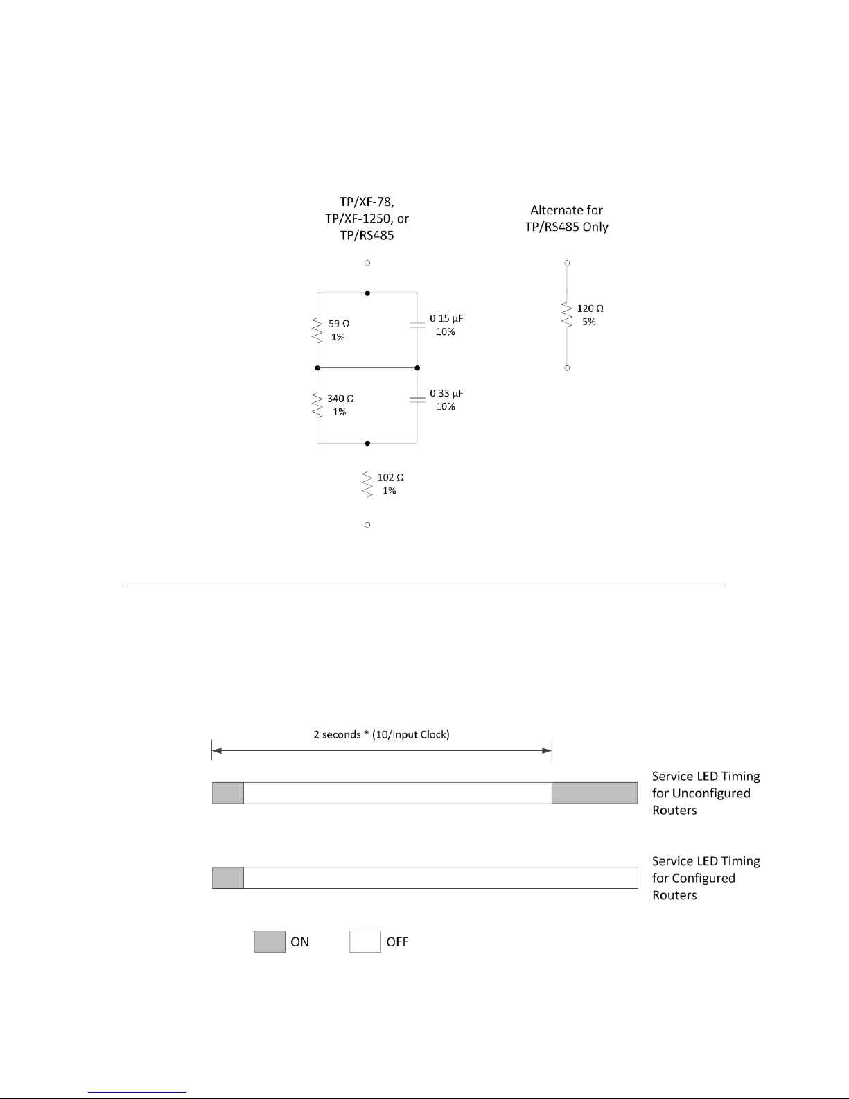
Proper electrical termination is essential for each twisted-pair channel. Failure
to terminate the network can degrade performance, and in some cases, eliminate
a device’s ability to communicate with other devices. For TP/XF and TP/RS485
channels, use the terminator circuits shown in Figure 31. You can also use the
terminators provided with the NodeBuilder FX Development Tool.
Figure 31. Network Termination Circuits for TP/XF and TP/RS485
Connecting Power
After the router is physically attached to the desired channels, power must be
supplied.
When power is connected to a router, the Service LED for each side changes state
as described in Figure 32. After a router is powered and configured, the Service
LEDs stay off, unless the service request button is pressed.
Networks
LonWorks Router User’s Guide 67
Figure 32. Router Service LED Timing
Page 78

Installing the Router on a Network
After a router is physically attached to a network, and powered-up, it must be
logically installed on the network. You can install a router using a network
management tool, such as the LonMaker Integration Tool.
Alternatively, you can use a custom network management tool that uses the
router network management messages defined in Chapter 7; this method is
recommended only for very simple networks with no more than a few routers
because of the complexity of calculating timing parameters and forwarding tables
for complex networks.
Router Installation with the LonMaker Integration Tool
The LonMaker Integration Tool is an end-user tool that supports installation of
routers and application devices. See Chapters 4 and 5 of the LonMaker User’s
Guide for a description of router installation. Specify the channel type within the
LonMaker New Router Wizard; see Appendix A, Communications Parameters for
LonWorks Routers, on page 81, for detailed communications parameters for each
channel type.
Important: Before commissioning the router from the LonMaker Integration
tool, be sure that you have programmed both halves of the router (for example,
see Configuring a Router 5000 Half-Router on page 53) and that the reset signals
for both halves are tied together (for example, see RST~ on page 30).
Router Installation with Network Management
Messages
You can install routers using the network management messages described in
Chapter 7, Network Management Messages, on page 71, and in Appendix B of the
Neuron Chip Data Book, but this process is only recommended for simple
networks with few routers. The process is similar to application device
installation described in the LonMaker User’s Guide.
To install a router with network management messages, follow these steps:
1. Change the router state to Unconfigured using the Set Node Mode
network management message.
2. Assign one or two domains, subnets, and node IDs to both sides of the
router using the Update Domain network management message.
When installing the router in one domain, the same domain must be
assigned to both sides.
When installing the router in two domains, the same domain must be
assigned as the first domain on both sides, and the same domain must be
assigned as the second domain on both sides.
3. Select a routing algorithm for both sides of the router using the Write
Memory network management message. Both sides must be set to use
the same algorithm.
68 Installing a LonWorks Router
Page 79

4. For configured routers, load the group and subnet routing tables on both
sides of the router using the Group or Subnet Table Download network
management message. There are 255 forwarding flags for subnets and
255 forwarding flags for groups on each side for each domain.
5. Initialize the routing tables using the Set Router Mode network
management message.
6. Change the router state on both sides of the router to Configured, on-line
using the Set Node Mode network management message.
Testing Router Installation
After a router has been installed, you can use the Query Status network
diagnostic message to ensure that it is operational. If no response is received,
query all intermediate routers to determine where the fault occurred. If the
router has been installed with the LonMaker Integration Tool, use the Test
command (described under “Testing Devices” in Chapter 6 of the LonMaker
User’s Guide) to query router status.
See the description of the Query Status message in the Standard Messages
section on page 72 for a description of the error codes returned by the Query
Status message.
LonWorks Router User’s Guide 69
Page 80

Page 81

7
Network Management Messages
This chapter describes network management messages for
ONWORKS routers. These messages are used for router
L
installation, as described in Chapter 6, Installing a
LonWorks Router, on page 65.
LonWorks Router User’s Guide 71
Page 82

Introduction
As described in Chapter 6, routers are installed using network management
messages. These messages are sent as explicit messages by a network
management tool, such as the LonMaker Integration Tool. Routers respond to
many of the same messages as any L
additional set of router-specific messages, as listed in Table 10.
ONWORKS device, but also have an
Table 10. Network Messages
Success
Network Message Type Request Code
Network Diagnostic 0x50 to 0x5F 0x31 to 0x3F 0x11 to 0x1F
Network Management 0x60 to 0x7D 0x21 to 0x3D 0x01 to 0x1D
Router Configuration 0x74 to 0x7E 0x34 to 0x3E 0x14 to 0x1E
Several router options are set using the Write Memory network management
message. These router options include specification of the routing algorithm,
buffer sizes, and non-priority output buffer queue count.
Response
Failed
Response
Standard Messages
Routers accept the standard network diagnostic and network management
messages listed in Table 11 and Table 12. These messages are described in
Appendix B of the Neuron Chip Data Book.
Table 11. Network Diagnostic Messages
Success
Network Diagnostic Message Request Code
Query Status 0x51 0x31 0x11
Response
Failed
Response
Proxy Command 0x52 0x32 0x12
Clear Status 0x53 0x33 0x13
Query XCVR Status 0x54 0x34 0x14
Network Management Message Request Code
Query ID 0x61 0x21 0x01
Respond to Query 0x62 0x22 0x02
72 Network Management Messages
Table 12. Network Management Messages
Success
Response
Failed
Response
Page 83

Success
Network Management Message Request Code
Update Domain 0x63 0x23 0x03
Leave Domain 0x64 0x24 0x04
Update Key 0x65 0x25 0x05
Query Domain 0x6A 0x2A 0x0A
Set Node Mode 0x6C 0x2C 0x0C
Read Memory 0x6D 0x2D 0x0D
Write Memory 0x6E 0x2E 0x0E
Checksum Recalculate 0x6F 0x2F 0x0F
Memory Refresh 0x71 0x31 0x11
The following exceptions apply to standard network management messages when
used with routers:
• The Query Status network diagnostic message reports two errors that are
unique to the router (159 [0x9F] and 164 [0xA4]). These errors are listed
in Appendix B of the Neuron Chip Data Book.
Response
Failed
Response
• The Set Node Mode network management message is automatically
processed by both sides of a router when it is used to place the router
offline and online (the APPL_OFFLINE and APPL_ONLINE options).
• When the Set Node Mode message is used to place a router offline, the
router stops forwarding, and all messages not addressed to the router are
dropped.
• The router does not respond to Set Node Mode messages that use a
broadcast address. Thus, broadcast Restart or Offline messages do not
stop the router and prevent the same broadcast message from reaching
destinations on the other side of the router. Routers must therefore be
restarted or taken offline using a Set Node Mode message addressed
directly to the router.
Router-Specific Messages
Router-specific network management messages are listed in Table 13 on page
74.
LonWorks Router User’s Guide 73
Page 84

Table 13. Router-Specific Network Management Messages
Success
Network Management Message Request Code
Set Router Mode 0x74 0x34 0x14
Group or Subnet Table Clear 0x75 0x35 0x15
Group or Subnet Table Download 0x76 0x36 0x16
Group Forward 0x77 0x37 0x17
Subnet Forward 0x78 0x38 0x18
Group No Forward 0x79 0x39 0x19
Subnet No Forward 0x7A 0x3A 0x1A
Group or Subnet Table Report 0x7B 0x3B 0x1B
Router Status 0x7C 0x3C 0x1C
Far Side Escape Code 0x7D ― ―
Response
Failed
Response
Router-Specific Network Management Messages
This section describes the router-specific network management messages listed
in Table 13.
Set Router Mode
This message instructs the router to perform one of several router-related tasks:
• The NORMAL option returns the router from the TEMP_BRIDGE mode.
• The INIT_RTR_TABLE option copies all forwarding tables from
EEPROM into the RAM tables for a configured router, or, sets all RAM
tables to flood for a learning router (this is the same action that occurs
after node reset).
• The TEMP_BRIDGE option causes the router to temporarily forward all
messages in the domain (until the next reset or Set Router Mode message
with the NORMAL option).
Note: The standard Set Node Mode message can be used to take the entire
router offline and online.
The Set Router Mode message affects both router sides. This message uses the
Request-Response protocol.
74 Network Management Messages
Page 85

typedef enum {
NORMAL = 0, // Not a temporary bridge.
INIT_RTR_TABLE = 1, // Copy forwarding tables from EEPROM
// for configured routers.
// Initialize forwarding tables for
// learning routers.
TEMP_BRIDGE = 2 // Temporarily a bridge until next reset
// or NORMAL router mode request.
} rtr_mode;
typedef rtr_mode NM_rtr_mode_request;
Group or Subnet Table Clear
This message clears all entries in either the group or subnet forwarding table for
a single domain for a single router side. The message is segmented to cover eight
byte sections to prevent lengthy EEPROM write operations.
This message uses the Request-Response protocol. The configuration checksum
in EEPROM is updated.
typedef struct {
unsigned group_or_subnet : 1; // 1 => Group, 0 => Subnet
unsigned domain_index : 1;
unsigned unused : 4;
unsigned index_times_8 : 2;
} NM_rtr_table_clear_request;
Group or Subnet Table Download
This message configures the entire group or subnet forwarding table in EEPROM
for the specified domain for a single router side. The download function is
segmented into eight-byte sections.
The least significant bit (LSB) of the table field maps to the lowest subnet or
group ID in the current set of table entries defined by the index_times_8 field.
A value of ‘1’ specifies that forwarding be enabled for the corresponding group or
subnet; a value of ‘0’ disables forwarding. Subnet 0 is used for special protocol
functions and is never marked for forwarding.
This message uses the Request-Response protocol. The configuration checksum
in EEPROM is updated. Each byte in the table entry includes routing flags for
eight subnets or groups.
typedef struct {
unsigned group_or_subnet : 1; // 1 => Group, 0 => Subnet
unsigned domain_index : 1;
unsigned unused : 4;
unsigned index_times_8 : 2;
unsigned table[8]; // Table data
} NM_rtr_table_downld_request;
Group Forward
This message sets the forwarding flag in the forwarding table for a given group in
the specified domain. If the ram_or_eeprom field is set, both the RAM and
LonWorks Router User’s Guide 75
Page 86

EEPROM flags are set, otherwise only the RAM flag is set, allowing temporary
forwarding for a given group.
This message uses the Request-Response protocol. The configuration checksum
in EEPROM is updated if EEPROM is changed.
typedef struct {
unsigned unused1 : 1;
unsigned domain_index : 1;
unsigned unused2 : 5;
unsigned ram_or_eeprom : 1; // 0 => RAM, 1 => RAM+EEPROM
unsigned group;
} NM_rtr_group_fwd_request;
Subnet Forward
This message sets the forwarding flag in the forwarding table for a given subnet
in the specified domain. If the ram_or_eeprom field is set, both the RAM and
EEPROM flags are set, otherwise only the RAM flag is set, allowing temporary
forwarding for a given subnet.
This message uses the Request-Response protocol. The configuration checksum
in EEPROM is updated if EEPROM is changed.
typedef struct {
unsigned unused1 : 1;
unsigned domain_index : 1;
unsigned unused2 : 5;
unsigned ram_or_eeprom : 1; // 0 => RAM, 1 => RAM+EEPROM
unsigned subnet;
} NM_rtr_subnet_fwd_request;
Group No Forward
This message clears the forwarding flag in the forwarding table for a given group
in the specified domain. If the ram_or_eeprom field is set, both the RAM and
EEPROM flags are cleared, otherwise only the RAM flag is cleared, allowing
temporary control of forwarding for a given group (see the Router Status message
on page 77).
This message uses the Request-Response protocol. The configuration checksum
in EEPROM is updated if EEPROM is changed.
typedef struct {
unsigned unused1 : 1;
unsigned domain_index : 1;
unsigned unused2 : 5;
unsigned ram_or_eeprom : 1; // 0 => RAM, 1 => RAM+EEPROM
unsigned group;
} NM_rtr_group_nofwd_request;
Subnet No Forward
This message clears the forwarding flag in the forwarding table for a given
subnet in the specified domain. If the ram_or_eeprom field is set, both the RAM
and EEPROM flags are cleared, otherwise only the RAM flag is cleared, allowing
temporary control of forwarding for a given subnet.
76 Network Management Messages
Page 87

This message uses the Request-Response protocol. The configuration checksum
in EEPROM is updated if EEPROM is changed.
typedef struct {
unsigned unused1 : 1;
unsigned domain_index : 1;
unsigned unused2 : 5;
unsigned ram_or_eeprom : 1; // 0 => RAM, 1 => RAM+EEPROM
unsigned subnet;
} NM_rtr_subnet_nofwd_request;
Group or Subnet Table Report
This message reports the current settings of either group or subnet forwarding
tables in EEPROM or RAM for the specified domain for a single router side. The
report function is segmented into eight byte sections.
Important: This message is supported by router firmware version 5 or later
only. Use of this message with earlier versions of the router firmware cause the
router to become inoperable.
This message uses the Request-Response protocol.
typedef struct {
unsigned group_or_subnet : 1; // 1 => Group, 0 => Subnet
unsigned domain_index : 1;
unsigned ram_or_eeprom : 1; // 0 => RAM, 1 => EEPROM
unsigned unused : 3;
unsigned index_times_8 : 2;
} NM_rtr_table_report_request;
typedef struct {
unsigned table[8]; // Table data
} NM_rtr_table_report_response;
Router Status
This message is used to report the router configuration and flood/normal modes.
This message uses the Request-Response protocol.
typedef enum {
CONFIGURED = 0,
LEARNING = 1,
BRIDGE = 2,
REPEATER = 3
} algorithm;
typedef enum {
NORMAL = 0, // Not a temporary bridge.
INIT_RTR_TABLE = 1, // Copy forwarding tables from EEPROM
// for configured routers.
// Initialize forwarding tables for
// learning routers.
TEMP_BRIDGE = 2 // Temporarily a bridge until next reset.
} rtr_mode;
LonWorks Router User’s Guide 77
Page 88

typedef struct {
algorithm type; // CONFIGURED, LEARNING, BRIDGE,
// or REPEATER
rtr_mode mode; // TEMP_BRIDGE or NORMAL
} NM_rtr_status_response;
Far Side Escape Code
When this message code is placed in the message, and is followed by any network
management or network diagnostic message (except the escape message itself),
that message is passed to the other (far) router side for processing. Any
responses are returned in the normal manner. This command allows network
management of the router side that is not directly addressable from a network
management tool.
The far side escape code is not required for the Set Node Mode network
management message when it is used to place the router offline and online (the
APPL_OFFLINE and APPL_ONLINE options). The offline and online commands
are automatically forwarded.
byte code; /* Destination: NM, code: 0x7E */
Router Options Set with Write Memory
The Write Memory network management message is used to change the routing
algorithm, buffer sizes, and buffer queue counts. To change these parameters,
perform the following steps:
1. Change the parameters using the Write Memory network management
message, as described in the following sections.
2. Reset the router using the Set Node Mode network management message.
Set Routing Algorithm
The routing algorithm is selected using a Write Memory network management
message with the following parameters:
mode = CONFIG_RELATIVE (2)
offset = 0x0037;
count = 1;
form = CNFG_CS_RECALC (4)
data = routing_algorithm;
The routing_algorithm value is a byte of type algorithm:
typedef enum {
CONFIGURED = 0,
LEARNING = 1,
BRIDGE = 2,
REPEATER = 3
} algorithm;
Set Buffer Size
The buffer sizes are selected using a Write Memory network management
message with the following parameters:
78 Network Management Messages
Page 89

mode = READ_ONLY_RELATIVE (1)
offset = 0x0019;
count = 1;
form = BOTH_CS_RECALC (1)
data = buffer_sizes;
The buffer_sizes value contains two nibble fields that control the size of both
the input and output buffers. The output size value also controls the priority
output buffer size. The default size is 66 bytes (or SIZE_66 = 0xB).
When changing this value, you should set both nibble fields to the same value.
Different values can be used if the maximum packet size is different for the two
directions through the router. The default setting for this byte is 0xBB. The
total number of bytes assigned to the buffer queues for a RTR-10 must not exceed
1254 bytes, as described in Message Buffers on page 13. A buffer size of less than
66 is not recommended because the router will not be able to forward network
management messages if the buffers are too small.
The size values are represented by a code of type buffer_size_entry:
typedef enum {
SIZE_20 = 0x2;
SIZE_21 = 0x3;
SIZE_22 = 0x4;
SIZE_24 = 0x5;
SIZE_26 = 0x6;
SIZE_30 = 0x7;
SIZE_34 = 0x8;
SIZE_42 = 0x9;
SIZE_50 = 0xA;
SIZE_66 = 0xB;
SIZE_82 = 0xC;
SIZE_114 = 0xD;
SIZE_146 = 0xE;
SIZE_210 = 0xF;
SIZE_255 = 0x0;
} buffer_size_entry;
Set Priority Output Buffer Queue Count
The priority output buffer queue count is selected using a Write Memory network
management message with the following parameters:
mode = READ_ONLY_RELATIVE (1)
offset = 0x001A;
count = 1;
form = BOTH_CS_RECALC (1)
data = queue_count;
The queue_count value contains two nibble fields. The most significant nibble
controls the number of priority output buffers. The least significant nibble must
be zero. The total number of bytes assigned to the buffer queues for a RTR-10
must not exceed 1254 bytes, as described Message Buffers on page 13.
The most significant nibble of queue_count is represented by a code of type
queue_count_entry:
LonWorks Router User’s Guide 79
Page 90

typedef enum {
COUNT_1 = 0x2;
COUNT_2 = 0x3;
COUNT_3 = 0x4;
COUNT_5 = 0x5;
COUNT_7 = 0x6;
COUNT_11 = 0x7;
COUNT_15 = 0x8;
COUNT_23 = 0x9;
COUNT_31 = 0xA;
COUNT_47 = 0xB;
COUNT_63 = 0xC;
} queue_count_entry;
Set Input and Non-Priority Buffer Queue
Count
The buffer queue counts are selected using a Write Memory network management
message with the following paramters:
mode = READ_ONLY_RELATIVE (1)
offset = 0x001C;
count = 1;
form = BOTH_CS_RECALC (1)
data = queue_counts;
The queue_counts value contains two nibble fields that control the count of
both the input and non-priority output buffer queues. The least significant
nibble controls the number of input buffers and the most significant nibble
controls the number of nonpriority output buffers. The default for this field is 15
non-priority output buffers (COUNT_15) and 2 input buffers (COUNT_2). The
total number of bytes assigned to the buffer queues for a RTR-10 must not exceed
1254 bytes, as described Message Buffers on page 13. The queue count for both
queues is represented by the source code as that for the Set Priority Output
Buffer Queue Count command on page 79.
80 Network Management Messages
Page 91

A
Communications Parameters for
LonWorks Routers
LONWORKS routers are initially programmed with
communications parameters as listed in this appendix.
Parameters for L
to the parameters defined by the L
Guidelines. Parameters specified as “Configurable” can be
changed by a network services tool.
These parameters only apply to routers with router
firmware version 5 or newer. The firmware version number
for a router can be determined with the LonMaker Test
command or with the Query Status network diagnostic
message.
Communications parameters for routers with version 4 or
older firmware should be re-installed to ensure that the
standard interoperable parameters are used.
ONMARK approved transceivers correspond
ONWORKS Interoperability
LonWorks Router User’s Guide 81
Page 92

Communications Parameters
Table 14, Table 15 on page 83, Table 16 on page 85, and Table 17 on page 86
together list the communications parameters for L
Table 14. Communications Parameters, Part 1
Parameter TP/XF-78 TP/XF-1250 TP/FT-10 TP/RS485-39
Transceiver ID 1 (0x01) 3 (0x03) 4 (0x04) 5 (0x5)
ONWORKS routers.
Media Isolated
Twisted Pair
Neuron Chip to
Transceiver Interface
Interface Bit Rate 78 kbps 1.25 Mbps 78 kbps 39 kbps
Input Clock 10 MHz 10 MHz 10 MHz 10 MHz
Minimum Clock Configurable;
Number of Priority Slots Configurable;
Average Packet Size Configurable;
Oscillator Accuracy 200 ppm 200 ppm 200 ppm 200 ppm
Differential Differential Single Ended Single Ended
default = 5
MHz
default = 4
slots
default = 15
bytes
Isolated
Twisted Pair
Configurable;
default = 10
MHz
Configurable;
default = 16
slots
Configurable;
default = 15
bytes
Free Topology
or Link Power
Configurable;
default = 5
MHz
Configurable;
default = 4
slots
Configurable;
default = 15
bytes
EIA-485
Twisted Pair
Configurable;
default = 5
MHz
Configurable;
default = 4
slots
Configurable;
default = 15
bytes
Oscillator Wakeup 0 µsec 0 µsec 0 µsec 0 µsec
Collision Detect (CD) No No No No
CD Term after Preamble N/A N/A N/A N/A
CD through Packet End N/A N/A N/A N/A
Bit Sync Threshold 5 bits 7 bits 4 bits 4 bits
Hysteresis 2 0 N/A N/A
Filter 1 0 N/A N/A
Network Bit Rate 78 kbps 1.25 Mbps 78 kbps 39 kbps
82 Communications Parameters for LonWorks Routers
Page 93

Parameter TP/XF-78 TP/XF-1250 TP/FT-10 TP/RS485-39
Alternate Rate N/A N/A N/A N/A
Wakeup Pin Direction N/A N/A N/A N/A
XCVR Controls Preamble N/A N/A N/A N/A
General Purpose Data N/A N/A N/A N/A
Allow Node Override N/A N/A N/A N/A
Receive Start Delay 2.9 bits 14.0 bits 9.0 bits 2.0 bits
Receive End Delay 0.0 bits 0.0 bits 0.0 bits 0.0 bits
Indeterminate Time 24.0 bits 25.0 bits 24.0 bits 4.0 bits
Min Interpacket Time 0.0 bits 0.0 bits 0.0 bits 0.0 bits
Turnaround Time 0 µsec 0 µsec 0 µsec 0 µsec
Missed Preamble 1.0 bits 4.0 bits 4.0 bits 1.0 bits
Preamble Length N/A N/A N/A N/A
Use Raw Data No No No No
Table 15. Communications Parameters, Part 2
Parameter RF-10 PL-10 PL-20C PL-20N
Transceiver ID 7 (0x07) 9 (0x09) 16 (0x10) 17 (0x11)
Media 49 MHz Radio
Power Line Power Line Power Line
Frequency
Neuron Chip to
Transceiver Interface
Single Ended Special
Purpose
Special
Purpose
Special
Purpose
Interface Bit Rate 4.9 kbps 625 kbps 156.3 kbps 156.3 kbps
Input Clock 5 MHz 10 MHz 10 MHz 10 MHz
Minimum Clock Configurable;
default = 5
MHz
Configurable;
default = 5
MHz
Configurable;
default = 1.25
MHz
Configurable;
default = 1.25
MHz
LonWorks Router User’s Guide 83
Page 94

Parameter RF-10 PL-10 PL-20C PL-20N
Number of Priority Slots Configurable;
default = 4
slots
Average Packet Size Configurable;
default = 15
bytes
Configurable;
default = 8
slots
Configurable;
default = 15
bytes
Configurable;
default = 8
slots
Configurable;
default = 15
bytes
Configurable;
default = 8
slots
Configurable;
default = 15
bytes
Oscillator Accuracy 200 ppm 200 ppm 200 ppm 200 ppm
Oscillator Wakeup 0 µsec 0 µsec 0 µsec 0 µsec
Collision Detect (CD) No N/A N/A N/A
CD Term after Preamble N/A N/A N/A N/A
CD through Packet End N/A N/A N/A N/A
Bit Sync Threshold 7 bits N/A N/A N/A
Hysteresis N/A N/A N/A N/A
Filter N/A N/A N/A N/A
Network Bit Rate 4.9 kbps 9412 bps 3987 bps 3987 bps
Alternate Rate N/A 0 bps N/A N/A
Wakeup Pin Direction N/A Output Output Output
XCVR Controls Preamble N/A Yes Yes Yes
General Purpose Data N/A 00 0A 00 00
00 00 00
4A 00 00 00
00 00 00
0E 01 00 00
00 00 00
Allow Node Override N/A Yes No No
Receive Start Delay 2.0 bits 1.0 bit 6.8 bits 6.8 bits
Receive End Delay 0.0 bits 10.4 bits 1.6 bits 1.6 bits
Indeterminate Time 9.8 bits 0.0 bits 0.0 bits 0.0 bits
Min Interpacket Time 0.0 bits 0.0 bits 17.5 bits 17.5 bits
Turnaround Time 0 µsec N/A N/A N/A
Missed Preamble 9.0 bits N/A N/A N/A
84 Communications Parameters for LonWorks Routers
Page 95

Parameter RF-10 PL-10 PL-20C PL-20N
Preamble Length N/A 36.7 bits 33.5 bits 33.5 bits
Use Raw Data No No No No
Table 16. Communications Parameters, Part 3
Parameter PL-30
TP/RS485625
TP/RS4851250 TP/RS485-78
Transceiver ID 18 (0x12) 10 (0x0A) 11 (0x0B) 12 (0x0C)
Media Power Line EIA-485
Twisted Pair
Neuron Chip to
Transceiver Interface
Special
Purpose
Single Ended Single Ended Single Ended
EIA-485
Twisted Pair
EIA-485
Twisted Pair
Interface Bit Rate 625 kbps 625 kbps 1.25 Mbps 78 kbps
Input Clock 10 MHz 10 MHz 10 MHz 10 MHz
Minimum Clock Configurable;
default = 5
MHz
Number of Priority Slots Configurable;
default = 12
slots
Average Packet Size Configurable;
default = 15
bytes
Configurable;
default = 5
MHz
Configurable;
default = 4
slots
Configurable;
default = 15
bytes
Configurable;
default = 5
MHz
Configurable;
default = 16
slots
Configurable;
default = 15
bytes
Configurable;
default = 5
MHz
Configurable;
default = 4
slots
Configurable;
default = 15
bytes
Oscillator Accuracy 200 ppm 200 ppm 200 ppm 200 ppm
Oscillator Wakeup 0 µsec 0 µsec 0 µsec 0 µsec
Collision Detect (CD) N/A No No No
CD Term after Preamble N/A N/A N/A N/A
CD through Packet End N/A N/A N/A N/A
Bit Sync Threshold N/A 4 bits 4 bits 4 bits
Hysteresis N/A N/A N/A N/A
Filter N/A N/A N/A N/A
LonWorks Router User’s Guide 85
Page 96

Parameter PL-30
TP/RS485625
TP/RS4851250 TP/RS485-78
Network Bit Rate 1882 bps 625 kbps 1.25 Mbps 78 kbps
Alternate Rate N/A N/A N/A N/A
Wakeup Pin Direction Output N/A N/A N/A
XCVR Controls Preamble Yes N/A N/A N/A
General Purpose Data 00 8A 00 00
N/A N/A N/A
00 00 00
Allow Node Override Yes N/A N/A N/A
Receive Start Delay 1.0 bit 2.0 bits 2.0 bits 2.0 bits
Receive End Delay 10.4 bits 0.0 bits 0.0 bits 0.0 bits
Indeterminate Time 0.0 bits 4.0 bits 4.0 bits 4.0 bits
Min Interpacket Time 0.0 bits 0.0 bits 0.0 bits 0.0 bits
Turnaround Time N/A 0 µsec 0 µsec 0 µsec
Missed Preamble N/A 1.0 bit 1.0 bit 1.0 bit
Preamble Length 36.7 bits N/A N/A N/A
Use Raw Data No No No No
Table 17. Communications Parameters, Part 4
Parameter FO-10 DC-78 DC-625 DC-1250
Transceiver ID 24 (0x18) 27 (0x1B) 28 (0x1C) 29 (0x1D)
Media Fiber Optic Direct
Neuron Chip to
Transceiver Interface
Interface Bit Rate 1.25 Mbps 78 kbps 625 kbps 1.25 Mbps
Input Clock 10 MHz 10 MHz 10 MHz 10 MHz
86 Communications Parameters for LonWorks Routers
Connect
Direct
Connect
Direct
Connect
Single Ended Differential Differential Differential
Page 97

Parameter FO-10 DC-78 DC-625 DC-1250
Minimum Clock Configurable;
default = 10
MHz
Number of Priority Slots Configurable;
default = 16
slots
Average Packet Size Configurable;
default = 15
bytes
Configurable;
default = 10
MHz
Configurable;
default = 0
slots
Configurable;
default = 15
bytes
Configurable;
default = 10
MHz
Configurable;
default = 0
slots
Configurable;
default = 15
bytes
Configurable;
default = 10
MHz
Configurable;
default = 0
slots
Configurable;
default = 15
bytes
Oscillator Accuracy 200 ppm 200 ppm 200 ppm 200 ppm
Oscillator Wakeup 0 µsec 0 µsec 0 µsec 0 µsec
Collision Detect (CD) Yes No No No
CD Term after Preamble Yes N/A N/A N/A
CD through Packet End Yes N/A N/A N/A
Bit Sync Threshold 4 bits 4 bits 4 bits 4 bits
Hysteresis N/A 0 0 0
Filter N/A 0 0 0
Network Bit Rate 1.25 Mbps 78 kbps 625 kbps 1.25 Mbps
Alternate Rate N/A N/A N/A N/A
Wakeup Pin Direction N/A N/A N/A N/A
XCVR Controls Preamble N/A N/A N/A N/A
General Purpose Data N/A N/A N/A N/A
Allow Node Override N/A N/A N/A N/A
Receive Start Delay 4.0 bits 1.0 bit 1.0 bit 1.0 bit
Receive End Delay 4.0 bits 0.0 bits 0.0 bits 0.0 bits
Indeterminate Time 4.0 bits 0.0 bits 0.0 bits 0.0 bits
Min Interpacket Time 8.0 bits 0.0 bits 0.0 bits 0.0 bits
Turnaround Time 0 µsec 0 µsec 0 µsec 0 µsec
LonWorks Router User’s Guide 87
Page 98

Parameter FO-10 DC-78 DC-625 DC-1250
Missed Preamble 4.0 bits 0.0 bits 0.0 bits 0.0 bits
Preamble Length N/A N/A N/A N/A
Use Raw Data No No No No
88 Communications Parameters for LonWorks Routers
Page 99

www.echelon.com
 Loading...