

ITS 3000
(Intelligent Transfer Switch 3000)
Installation and Operation Manual
An ISO 9001:2000 Company

Contents
1. Safety Information.............................................2
2. Package Contents...............................................3
3. Introduction......................................................4
3.1. What is ITS for?.......................................4
3.2. Redundancy.............................................4
3.3. Double Backup.........................................5
3.4. Front View...............................................5
3.5. Rear View................................................5
4. Working Truth Table of ITS 3000..........................6
5. Installation Procedure.........................................7
6. Specification.....................................................8
7. Our other products............................................8
8. Our Contact Information ....................................9
Installation and Operation Manual

1. Safety Information
Read the below listed instruction before installing or
operating your E&C ITS 3000.
ØCheck whether the received materials are in good
condition.
ØTo reduce the risk of electric shock disconnect the ITS
3000 from the power outlet before installing or
connecting to other equipment. Reconnect the power
cord only after all connections are made.
ØAny kind of metallic connector should be handled after
the power has been removed.
ØConnect the equipment to a three-wire AC outlet (two
poles plus ground) that is connected to appropriate
branch circuit/mains protection (a fuse or circuit
breaker). Connection to any other type of receptacle
may result in a shock hazard.
ØTo switch off and disengage the ITS 3000, press and
hold both UPS Off buttons for more than one second to
switch off the equipment, then disconnect the ITS 3000
from the AC power outlet.
ØPluggable equipment includes a protective earth
conductor which carries the leakage current from the
load devices (computer equipment). Total leakage
current must not exceed 3.5 mA.
Installation and Operation Manual
Page 2

Installation and Operation Manual
2. Package Contents
The package contains the following.
Material Description Qty (Nos.)
ITS 3000 1
Power Cord (Input) 3
Power Cord (Output) 2
Installation and Operation Manual 1
Note:
Check whether all the above mentioned materials are received inact
and report immediately to the shipping agent if there are any
damages in transit. If you find any of the above contents missing or
any other problem, please report immediately to E&C Help Desk 080-
28397120 / 28397121.
Page 3

3. Introduction
3.1. What is ITS for?
ITS stands for Intelligent Transfer Switch. The function of the
ITS is to ensure supply of power to the load from multiple
power sources by switching from one to another when any of
the input sources fails, without interruption. Source and
can be connected with UPS and source can be the AC Utility
or Stabilizer or Generator.
3.2. Redundancy
When all the above said three sources are available, during
the operation if UPS-1 fails the output supply of ITS 3000 will
be transferred to UPS-2 automatically without any affect to
the connected load and also UPS-1 can be removed for
repairing without any interruption. If UPS-2 also fails, the
output supply of ITS 3000 will be transferred to AC Utility or
Generator automatically without any affect to the connected
load and UPS-2 can be removed for repairing without any
interruption.
UPS 1
UPS 2
UPS 3 /
AC Utility
ITS
Load
Installation and Operation Manual
Page 4
3.3. Double Backup
When AC fails, the entire load will be taken care by UPS-1 and
UPS-2 will be running without any load. If UPS-1 is shutting
down due to Battery low, UPS-2 will take care of the entire
load automatically.
3.4. Front View
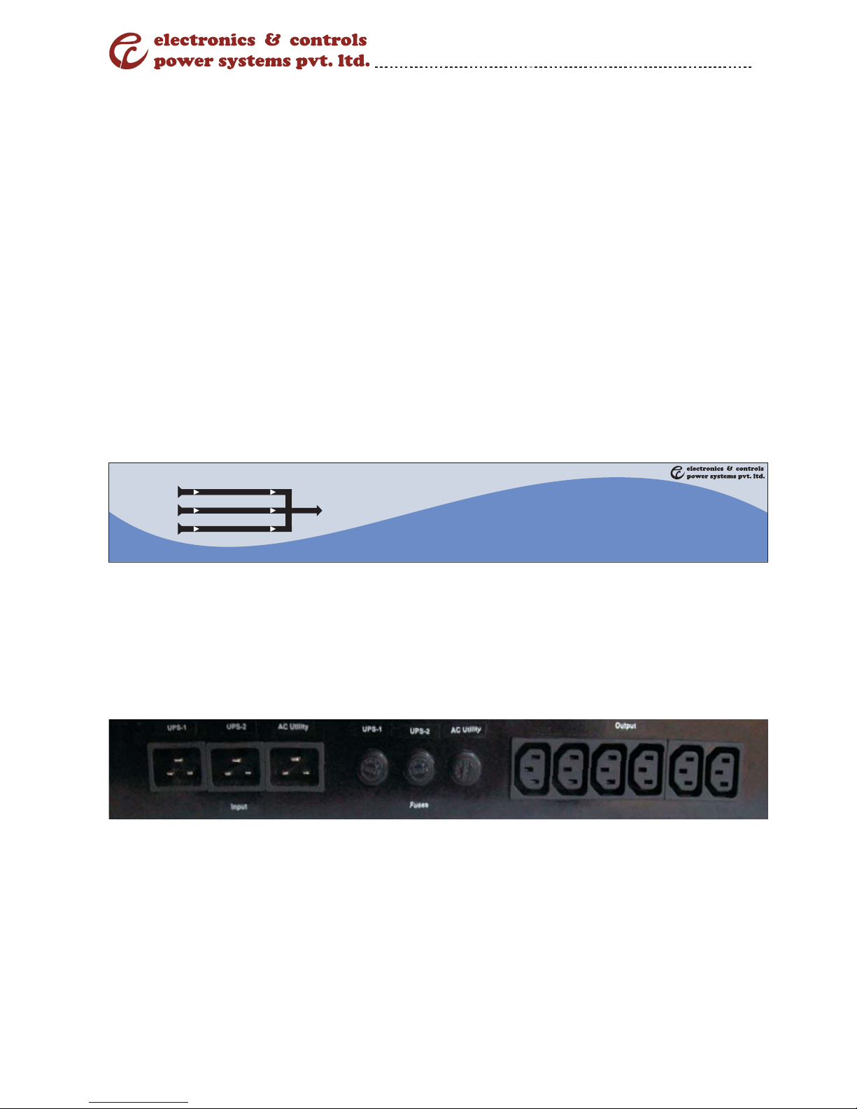
3.5. Rear View
Installation and Operation Manual
Page 5
ITS 3000
Source Load On
UPS 1 UPS 1
UPS 2 UPS 2
AC Utility AC Utility
Load

Installation and Operation Manual
4. Working Truth Table of ITS 3000
UPS-1 UPS-2 AC Utility Load ON
On On On UPS-1
Off On On UPS-2
Off Off On AC Utility
On Off On UPS-1
On Off Off UPS-1
On On Off UPS-1
Off On Off UPS-2
Page 6

5. Installation Procedure
Step 1: Do the physical verification of the unit after delivery.
Step 2: Before installation of the ITS 3000, please ensure that the
UPS1, UPS2 and AC Utility are having common line (phase).
Step 3: Before connecting supply to ITS 3000 please verify the L,
N and earth connection properly.
Step 4: Connect AC Utility supply to ITS 3000, as per given socket
and observe the LED indications on the front panel (AC Utility – ON
and load on AC Utility). Then check the output supply.
Step 5: Connect UPS-2 supply to ITS 3000, as per given socket
and observe the LED indications on the front panel (UPS-2 – ON
and load on UPS-2). After 10 sec delay, load supply automatically
changes from AC Utility to UPS-2. Then check the output supply.
Step 6: Connect UPS supply to ITS 3000 as per given socket and
observe the LED indications on the front panel (UPS-1 – ON and
load on UPS-1). After 10 sec delay, load supply automatically
changes from UPS-2 to UPS-1. Then check the output supply.
Step 7: Connect the load to ITS 3000.
Installation and Operation Manual
Page 7

6. Specification
Model E&C Intelligent Transfer Switch 3000
Capacity Current 16 Amp
Voltage 220/230/240VAC
Voltage Rating 200 – 270VAC
Frequency 46Hz to 53Hz
Transfer Time Typical <=15ms
Indicator LED Indicator Comprehensive 6 LEDs for indicating unit
working status
Protection Full protection Overload protection
Physical Dimension
(DxWxH)mm
280x350x70 (2U)
Net Weight Approx. 8Kg
Environment Operating Environment 0C - 45C, 20% - 85% relative humidity (non-
condensing)
Noise Level Less than 25dB
7. Our other products
vOn-line UPS
vInverters
vServo Controlled Voltage
Stabilizer
vEnergy Saver
vIsolation Transformers
vBatteries
vBattery Chargers
vIntelligent Power Module
vRemote Monitoring Solutions
Installation and Operation Manual
Page 8

8. Our Contact Information
Head Office
29/A, 2nd Phase, Peenya Industrial Area, Bangalore - 560 058, India.
Tel No : +91-80-28371974 / 28379401, Fax No : +91-80-28391587
For sales enquiries contact : sales@eandcpower.com
Regional Sales Offices
wAhmedabad wBangalore wChandigarh wChennai wCochin wHyderabad
w Indore w Jaipur w Kolkata w Lucknow w Mumbai w New Delhi
Service Locations
• Agra
• Ahmedabad
• Aurangabad
• Agartala
• Bangalore
• Baroda
• Bhopal
• Bhubaneshwar
• Chandigarh
• Chennai
• Cochin
• Coimbatore
•
Calicut
• Dehradun
• Guwahati
• Gwalior
• Hubli
• Hyderabad
• Indore
• Jabalpur
• Jaipur
• Jammu
• Kanpur
• Kolkata
• Kot t ayam
• Ludhiana
• Lucknow
•
•
Madurai
Meerut
• Mumbai
• Munnar
• Mangalore
• Mysore
• Nagpur
• New Delhi
• Ongole
• Palakkad
• Patna
• Pondicherry
• Pune
• Raipur
• Ranchi
• Rajamundry
• Salem
• Srinagar
• Tirupati
• Trichy
• Tirunelveli
• Trivandrum
• Udaipur
• Vizag
• Vijayawada
• Varanasi
Works
A-95(BIS), PIPDIC Industrial Area, Mettupalayam, Pondicherry - 605 009,
India. Tel No : +91-413-2277241, Fax No : +91-413-4302241
For Service, Call our Helpline......... Tel No: 91-80-28397120 / 28397121
www.eandcpower.com
Installation and Operation Manual
Page 9
 Loading...