

Page 1
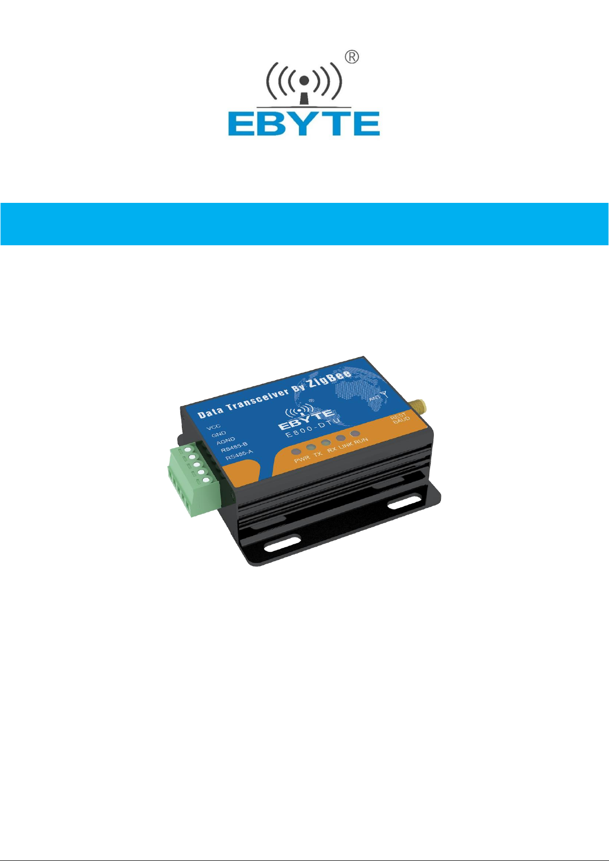
ZigBee Ad Hoc Network Wireless Modem
E800-DTU(Z2530-485-27) User Manual
Chengdu Ebyte Electronic Technology Co.,Ltd.
Page 2

E800-DTU Wireless Data Transmission Modem E800-DTU(Z2530-485-27) User Manual
Copyright ©2012–2017, Chengdu Ebyte Electronic Technology Co.,Ltd 1
1. Introduction
1.1. Product Introduction
The E800-DTU (Z2530-485-27) is a ZigBee-based wireless modem with various functions such as transparent transmission,
protocol transmission, and AT configuration etc. As a communication medium, wireless data transmission modem has certain
scope of application same as fiber, microwave and bright line. It provides real-time, reliable data transmission of monitoring
signals in private networks under special conditions, featuring low cost, convenient installation and maintenance, strong
diffraction ability, flexible networking structure and long coverage, and suitable for the occasions with many points while
scattered and complex geographical environment. It can be connected to data terminals such as PLC, RTU, rain gauge and level
gauge.
1.2. Features
★ All core components are original imported, Compared with the current imported wireless modem, it features the most
advanced, the smallest and has the best price.
★ Different transmit power are available, and all technical indicators meet European industrial standards.
★ With a temperature compensated crystal, the frequency stability is better than ±2ppm.
★ Operating temperature range: -40 to +85 DEG C, adapt to the harsh working environment, the real industrial products.
★ All aluminum alloy casing, compact size, easy installation, good heat dissipation; perfect shielding design, good
electromagnetic compatibility and strong anti-interference ability.
★ Multiple protection functions such as reverse power protection, over-current protection, and antenna surge protection greatly
increase the reliability of the radio.
★ Powerful software features, all parameters, such as power, frequency, address ID, etc., can be programmed.
★ Built-in watchdog, and precise time layout, once an exception occurs, the module will automatically restart, and can continue
to work according to the previous parameter settings.
Page 3

E800-DTU Wireless Data Transmission Modem E800-DTU(Z2530-485-27) User Manual
Copyright ©2012–2017, Chengdu Ebyte Electronic Technology Co.,Ltd 2
1.3. Characteristics
No.
Characteristics
Description
1
Role switching
The user can use the serial port command to let the device switch between the three types of coordinator,
router and terminal.
2
Automatic networking
Supports power-on automatic networking. The coordinator automatically builds up the network by power,
and the terminals and routers automatically search and join the network.
3
Network self-healing
Lost network automatic reconnection function. The network intermediate node is lost, and other networks
automatically join or maintain the original network. (The isolated node automatically joins the original
network, and the non-isolated node maintains the original network.)
The coordinator is lost and there are non-isolated nodes in the original network. The coordinator can join
the network again or the coordinator of the original PAN_ID set by the same user can join the original
network.
5
Data retention time
setting
In the state of the coordinator and router, the user can set the data storage time and use it in conjunction
with the terminal in the sleep mode to save the data of the terminal device and send the data to the terminal
after the terminal wakes up.
Save up to 3 pieces of data, if it is exceeded, automatically clear the first data! After the data is saved, the
data heap is automatically cleared.
6
Automatic resend
In single broadcast(point transmission) mode, when the device fails to send to the next node, it
automatically retransmits every message three times.
7
Automatic routing
The module supports network routing function. Routers and coordinators carry network data routing
functions, and users can form multi-hop networks.
8
Support encryption
protocol
The module uses AES 128-bit encryption to change network encryption and anti-listening. Users can
change the network key by themselves, and the devices with the same network key can communicate
normally.
9
Support Serial Port
Configuration
Module built-in serial instructions, users can configure (view) the parameters and functions of the module
through the serial instructions.
10
Multi-type data
communication
Supports all-network broadcast, multicast and on-demand (single broadcast) functions. Several
transmission methods are also supported in broadcast and single broadcast modes, please refer to the
details.
11
Multiple working mode
selection
It supports three working modes: transparent transmission mode, semi-through mode, protocol mode, and
user can switch freely.
12
Channel change
Supports 16 channel changes from 11 to 26 (2405~2480MHZ), and different channels correspond to
different frequency bands.
13
Network PAN_ID change
Any switch of the network PAN_ID, the user can customize the PAN_ID to join the corresponding
network or automatically select the PAN_ID to join the network.
14
Serial Port Baud Rate
Change
The user can set the baud rate up to 1M, default digit is 8 bits, stop bit is 1 bit, no parity bit.
15
Short address collection
The user can find the corresponding short address according to the module MAC address (unique, fixed)
that has joined the network.
16
Instruction format
switching
This module supports AT command and HEX command, which are easy to configure.
17
Module reset
The user can reset the module through the serial port command.
18
One-click Recovery Baud
Rate
This module supports one-button recovery of baud rate. This function can be used when the user forgets
the baud rate. The default baud rate is 115200.
19
Restore factory settings
Users can restore the factory settings of the module through serial port commands.
1.4. Serial Products
SN.
Model Number
RF Chip
Frequency
Hz
Air Data Rate
bps
Power
dBm
Interface
Distance
km
Antenna Interface
1
E800-DTU
(Z2530-485-27)
CC2530
2.4G
250K
27
RS485
2.5
SMA-K
2
E800-DTU
(Z2530-485-20)
CC2530
2.4G
250K
20
RS485
1.0
SMA-K
★ The E18 modules can communicate with the above model★
Page 4

E800-DTU Wireless Data Transmission Modem E800-DTU(Z2530-485-27) User Manual
Copyright ©2012–2017, Chengdu Ebyte Electronic Technology Co.,Ltd 3
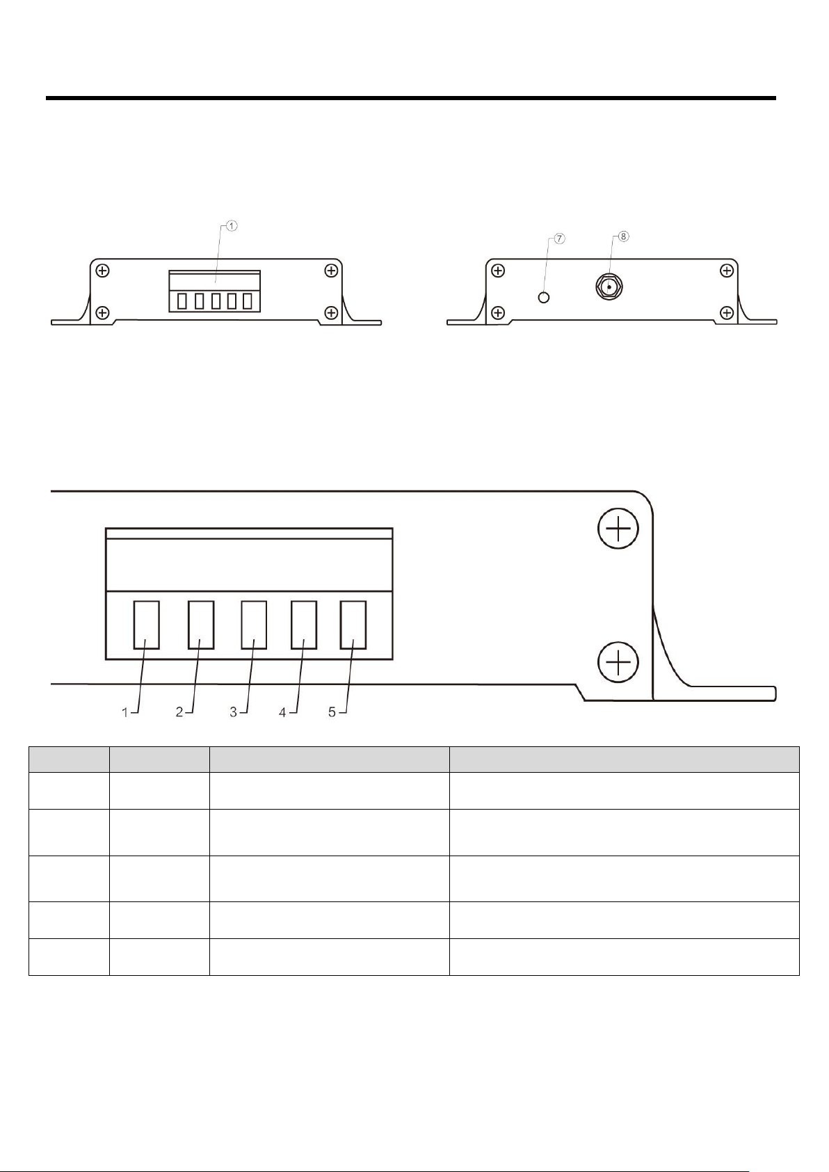
2. Installation Size
2.1. Department instructions
Pin No.
Name
Function
Description
1
3.81mm Terminals
Communication interface
power interface
Standard RS-485 interface and crimped power interface
2 PWR-LED
Power Indicator
Red, always on when the power is turned on
3 TX-LED
Sending indicator
Yellow, flashing when sending data
4 RX-LED
Receiving indicator
Yellow, flashing when receiving data
5 LINK-LED
Connection indicator
Red, be off when connected to the network, always on when there is no
network.
6 RUN-LED
Running lights
Red, system operation instructions, extinguish means normal operation,
constant light means running error.
7
Baud Rate Reset Switch
Tact Switch
Press and reset the baud rate(115200)
8 Antenna interface
SMA-K interface
External thread, 10mm long, characteristic impedance 50Ω
Page 5
E800-DTU Wireless Data Transmission Modem E800-DTU(Z2530-485-27) User Manual
Copyright ©2012–2017, Chengdu Ebyte Electronic Technology Co.,Ltd 4
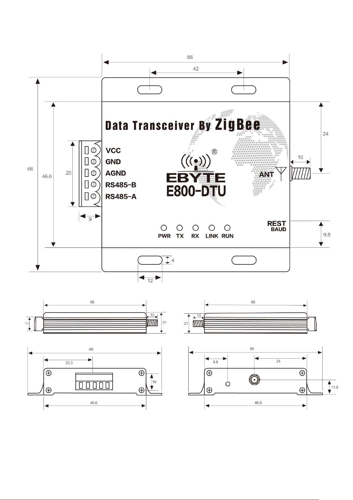
2.2. Product Size
单位:毫米
Page 6
E800-DTU Wireless Data Transmission Modem E800-DTU(Z2530-485-27) User Manual
Copyright ©2012–2017, Chengdu Ebyte Electronic Technology Co.,Ltd 5
3. Interface Definition
3.1. Power Interface Description
The user needs to use the VCC and GND terminal in ① to supply power. The E800-DTU can be powered by 8~28V DC. It
is recommended to use 12V or 24V DC power supply.
3.2. RS485 Interface Description
The E800-DTU (Z2530-485-27) uses the RS485 communication protocol. How to connect the communication cable, please
select the corresponding interface crimping wire in the ① 3.81mm terminal block. See below for details.
Pin No.
Definition
Function
Description
1
VCC
Crimp power connector, positive
8~28V DC, 12V or 24V is recommended
2
GND
Crimp power connector, positive
The negative pole of the power supply is connected to the
system and the housing.
3
AGND
Common ground interface
It can be connected with the grounding end of external
equipment, or can not be processed.
4
RS485-B
Serial port terminal
Externally connected to the B of other RS485 devices
5
RS485-A
Serial port terminal
Externally connected to the A of other RS485 devices
★ Note: The modem will be poor communication when connecting multiple devices, while connecting a single device is not, please
try to parallel connect 120Ω resistor between 485_A terminal and 485_B terminal.
Page 7

E800-DTU Wireless Data Transmission Modem E800-DTU(Z2530-485-27) User Manual
Copyright ©2012–2017, Chengdu Ebyte Electronic Technology Co.,Ltd 6
4. Function
4.1. Working Mode
Mode
Node Type
Description
Data communication
display mode
Mode1
(Transparent
transmission mode)
Coordinator
Serial data is transmitted to non-sleeping devices in the network through
broadcasting.
Data carrier formats can be
configured by instructions:
1. Display the mac address
of sender
2. 2Display the short
address of sender
3. Display the RSSI value
of the shortest path of the
message
(Configure display mode
as no display and any one or
more display modes )
Router
The serial port data is transparently transmitted to the coordinator through
on-demand. (Note:The end device cannot receive the transparent data
of mode 1 in sleep mode)
Terminal
Mode 2
(Semi-transparent
mode)
Coordinator
The module transmits in a full protocol according to the fixed format of the
data transmission.On-demand, broadcast, multicast are available.
Please refer to "HEX Data Communication Instructions" for details.
Router
The serial data is transparently transmitted to the coordinator via on-demand.
Terminal
Mode3
(Protocol mode)
Coordinator
The module transmits in a full protocol according to the fixed format of the
data transmission.On-demand, broadcast, multicast are available.
Please refer to "HEX Data Communication Instructions" for details.
N/A
Router
Terminal
Note: Only mode 3 can be selected for GPIO function configuration. Any mode can communicate with each other without affecting each other.
4.2. Introduction to protocol mode communication
No.
Usage
method
Description
1
Broadcast
In the case of joining the network, users can broadcast on the whole network according to the instructions (divided into
three broadcast modes)
1、Broadcast mode 1 ——The message is broadcast to all devices in the network.
2、Broadcast mode 2 ——The message is broadcast to devices that only receive on (except sleep mode).
3、Broadcast mode 3 ——The message is broadcast to all full-featured devices (routers and coordinators).
2
Group
broadcast
In the case of joining the network, users can multicast all the non-dormant devices in the network.
3
point
broadcast
In the case of joining the network, users can communicate with devices on the network in a short address according to the
command (divided into three broadcast modes)
1、Transparent transmission——(No information carried)
2、Short address method——(Short address as the carried information)
3、MAC address method——(MAC address as the carried information)
Note: Please refer to the “HEX Data Communication Instructions” for details.
Page 8
E800-DTU Wireless Data Transmission Modem E800-DTU(Z2530-485-27) User Manual
Copyright ©2012–2017, Chengdu Ebyte Electronic Technology Co.,Ltd 7
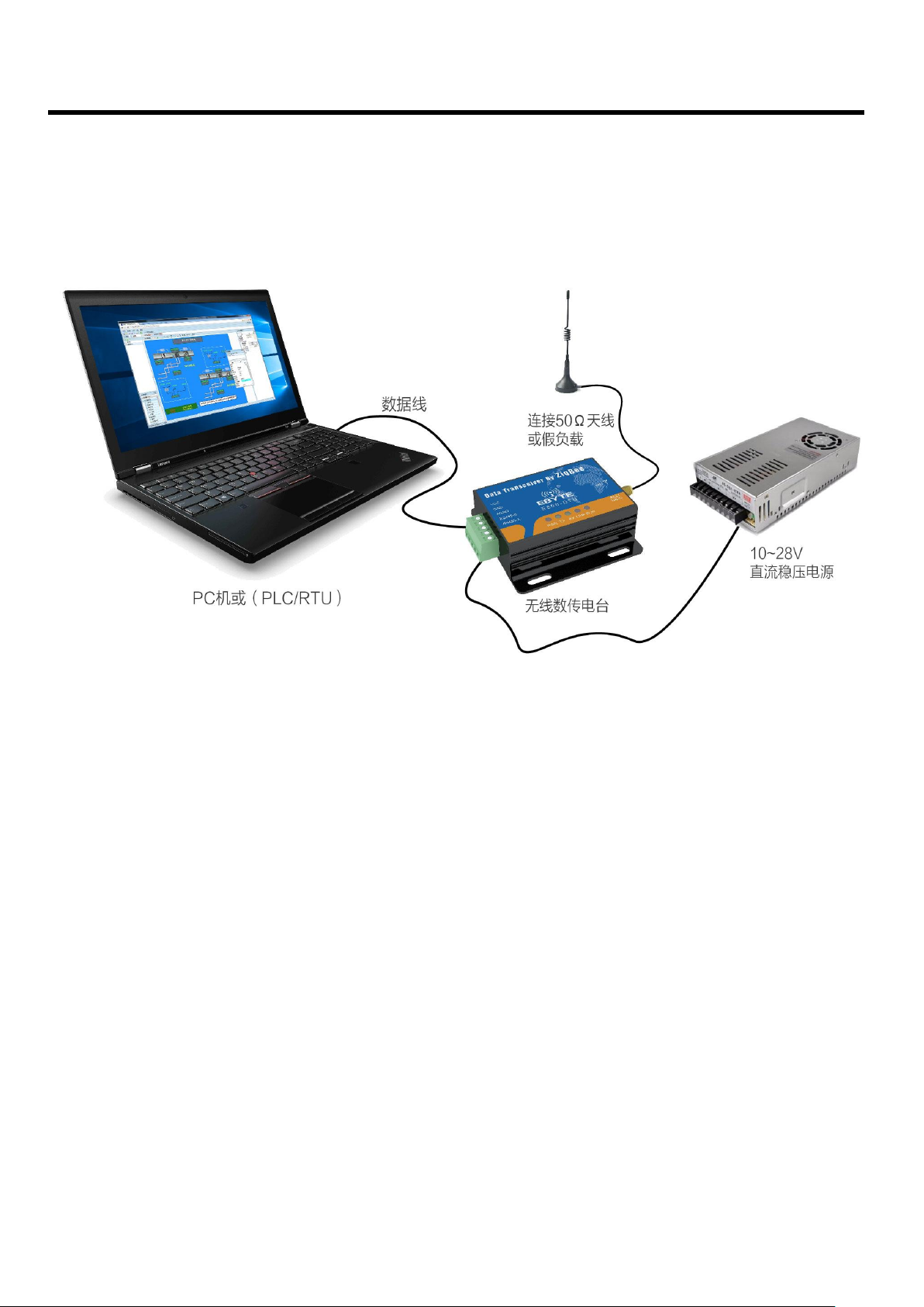
5. Quick Start
5.1. Use Connection Diagram
• ZigBee ad hoc network module is simple and easy to use. In order to let users be familiar with this products quickly, this
section will guide users to configure and communicate in various modes through simple configuration. The default operation
mode is mode 3 (protocol mode).
5.2. Network formation and communication
Page 9

E800-DTU Wireless Data Transmission Modem E800-DTU(Z2530-485-27) User Manual
Copyright ©2012–2017, Chengdu Ebyte Electronic Technology Co.,Ltd 8
No.
Note
1
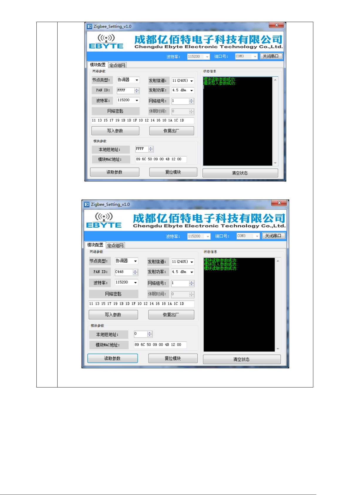
【Create network】:
① Connect the Zigbee-DTU through USB to RS485 board.
② Open the PC software "Zigbee_Setting_V1.1", select the port number, set the serial baud rate (default 115200),
and open the serial port.;
③ Click “Read Parameters‘’ to read module parameters
④ Select the node type as the coordinator and write the parameters. Wait for the coordinator to start creating the
network, and the user can view the module parameters.
Configure network parameters:(PAN ID is automatic when it’s FFFFFF)
Page 10
E800-DTU Wireless Data Transmission Modem E800-DTU(Z2530-485-27) User Manual
Copyright ©2012–2017, Chengdu Ebyte Electronic Technology Co.,Ltd 9
Read parameters after the network is built:
⑤ Choose another module and set it as a router or terminal according to the same steps (the module default as a
terminal, users don’t need to configure, our test is a terminal).
Page 11

E800-DTU Wireless Data Transmission Modem E800-DTU(Z2530-485-27) User Manual
Copyright ©2012–2017, Chengdu Ebyte Electronic Technology Co.,Ltd 10
2
【Communication test】:
① Click “fixed point networking” of coordinator and terminal in the host computer. The corresponding
communication information can be shown:
Coordinator:
Page 12

E800-DTU Wireless Data Transmission Modem E800-DTU(Z2530-485-27) User Manual
Copyright ©2012–2017, Chengdu Ebyte Electronic Technology Co.,Ltd 11
Terminal:
② Point broadcast In order to facilitate user’ observation, this experiment is HEX transmission mode.
If you do not know the device address, please enter the corresponding MAC address and click to get the network
address. The short address of coordinator is 0.
③ In three modes, enter any content in the sending area and click send.
transparent transmission:
Coordinator to terminal:
Page 13

E800-DTU Wireless Data Transmission Modem E800-DTU(Z2530-485-27) User Manual
Copyright ©2012–2017, Chengdu Ebyte Electronic Technology Co.,Ltd 12
Terminal to coordinator:
Network address:
Coordinator to terminal:
发送端网络短地址
Page 14

E800-DTU Wireless Data Transmission Modem E800-DTU(Z2530-485-27) User Manual
Copyright ©2012–2017, Chengdu Ebyte Electronic Technology Co.,Ltd 13
Terminal to coordinator:
MAC address:
Coordinator to terminal:
Coordinator to terminal:
Group broadcast:
发送端网络短地址
发送端网络短地址
发送端 MAC 短地址
Page 15

E800-DTU Wireless Data Transmission Modem E800-DTU(Z2530-485-27) User Manual
Copyright ©2012–2017, Chengdu Ebyte Electronic Technology Co.,Ltd 14
Broadcast:(The broadcast only performs in mode one, the whole network broadcast mode experiment, and users test
other modes themselves.)
Data function transmission needs to embody its own characteristics in the case of multi-node network, users can test
themselves!
6. User instruction set
For user convenience, the E800-DTU (Z2530-485-27) module uses two instruction formats, the AT command format and the
HEX command format. This DTU defaults as the HEX command mode, in this mode, serial assistant is used to send +++
instructions and enter the temporary AT instruction mode. AT command can be used to configure, input AT + EXIT to exit
temporary AT command.
Note:
1 Prompt information for serial data format error
HEX command format : F7 FF
AT command format : +ERROR<CR><LF>
2 Prompt information for coordinator device building network:
HEX command format : FF FF
AT command format : Builded network<CR><LF>
3 Prompt information for devices joining the network
HEX command format : FF AA
AT command format : Joined network<CR><LF>
4 Prompt information for module device has no network or lost network
HEX command format : FF 00
AT command format : No network<CR><LF>
5 <CR> means:0x0D
6 <LF>means:0x0A
Page 16

E800-DTU Wireless Data Transmission Modem E800-DTU(Z2530-485-27) User Manual
Copyright ©2012–2017, Chengdu Ebyte Electronic Technology Co.,Ltd 15
6.1. HEX Instruction Set
Instruction description
Instruction format
Instruction examples
Read device type
Send:FE 01 01 FF
Return:FB dev_type
Send:FE 01 01 FF
Return:FB 02
Read network status
Send:FE 01 02 FF
Return:FB nwk_state
Send:FE 01 02 FF
Return:FB 01
Read network PAN_ID
Send:FE 01 03 FF
Return:FB pan_id
Send:FE 01 03 FF
Return:FB 02 F4
Read network key
Send:FE 01 04 FF
Return:FB key
Send:FE 01 04 FF
Return:FB 11 13 15 17 19 1B 1D 1F 10 12 14 16 18 1A 1C
1D
Read short address of local
network
Send:FE 01 05 FF
Return:FB ShortAddr
Send:FE 01 05 FF
Return:FB F2 EF
Read local MAC address
Send:FE 01 06 FF
Return:FB Mac_Addr
Send:FE 01 06 FF
Return:FB 89 6C 50 09 00 4B 12 00
Read short address of parent
network
Send:FE 01 07 FF
Return:FB Coor_shortAddr
Send:FE 01 07 FF
Return:FB 00 00
Read MAC address of parent node
FE 01 08 FF
Return:FB Coor _Mac_Addr
Send:FE 01 08 FF
Return:FB 20 39 EA 0A 00 4B 12 00
Read Network Group Number
Send:FE 01 09 FF
Return:FB group
Send:FE 01 09 FF
Return:FB 01
Read communication channel
Send:FE 01 0A FF
Return:FB channel
Send:FE 01 0A FF
Return:FB 0B
Read transmitting power
Send:FE 01 0B FF
Return:FB txpower
Send:FE 01 0B FF
Return:FB 04
Read serial port baud rate
Send:FE 01 0C FF
Return:FB baud
Send:FE 01 0C FF
Return:FB 09
Read sleep state (terminal node is
valid )
Send:FE 01 0D FF
Return:FB sleep_time
Send:FE 01 0D FF
Return:FB 05
Read the save time of node data
(router and coordinator are valid)
Send:FE 01 0E FF
Return:FB 1E
Send:FE 01 0E FF
Return:FB 1E
Read all data of the device
Send:FE 01 FE FF
Return:FB all_info
Send:FE 01 FE FF
Return:FB 02 01 02 F4 11 13 15 17 19 1B 1D 1F 10 12 14 16
18 1A 1C 1D F2 EF 89 6C 50 09 00 4B 12 00 00 00 20 39 EA
0A 00 4B 12 00 01 0B 04 09 05
Get the short address of any MAC
address in the network
Send:FE 09 10 Mac_Addr FF
Return:FB shortAddr
Send:FE 09 10 AF 99 E9 0A 00 4B 12 00 FF
Return:FB 08 35
Read remote/local GPIO input and
output status
Command:FE 04 20 addr gpiox FF
Return:FB 20 addr In/Out
FE 04 20 F9 DE 04 FF
Read remote/local GPIO level
Command:FE 04 21 addr gpiox FF
Return:FB 21 addr In/Out level
FE 04 21 FF FF 04 FF
Read remote/local PWM status
Command:FE 04 22 addr 22 FF
Return:FB 22 addr period duty1
duty2 duty3 duty4 duty5
FE 04 22 FFFF 22 FF
Read remote/local ADC status
Command:FE 04 23 addr pin FF
Return:FB 23 addr adc_value
FE 04 23 FF FF 01 FF
Page 17

E800-DTU Wireless Data Transmission Modem E800-DTU(Z2530-485-27) User Manual
Copyright ©2012–2017, Chengdu Ebyte Electronic Technology Co.,Ltd 16
6.2. HEX parameter description
6.2.1. Network type
dev_type: 00 coordinator
01 router
02 terminal(default)
6.2.2. Network Status
nwk_state: 00 No network
01 Network exists
6.2.3. Network PAN_ID
pan_id: 0000~FFFE fixed network PAN_ID
FFFF stochastic network PAN_ID
6.2.4. Network Keys
key: 16-bit network key
6.2.5. Network short address
ShortAddr: 2 Byte address
6.2.6. MAC address
Mac_Addr: 8 Byte address
6.2.7. Parent node network short address
Coor_shortAddr:2 Byte address
6.2.8. Parent node MAC address
Coor_Mac_Addr: 8 Byte address
6.2.9. Network group number
group: Group number range 1~99(default 1)
6.2.10. Network Channel
channel: Channel range 11~26(default 11)
6.2.11. Transmit power
txpower:
Power parameter txpower comparison table without PA/with PA
Page 18

E800-DTU Wireless Data Transmission Modem E800-DTU(Z2530-485-27) User Manual
Copyright ©2012–2017, Chengdu Ebyte Electronic Technology Co.,Ltd 17
txpower
power (dBm)
txpower
Power (dBm)
00
-3 / 7 03
2.5 / 24
01
-1.5 / 19
04
4.5 / 27 (default)
02
0 / 22 05
6.2.12. Serial Port Baud Rate
baud:
Baud rate parameters comparison table
baud
Baud rate
baud
Baud rate
00
2400 08
76800
01
4800 09
115200(default)
02
9600 0A
128000
03
14400
0B
230400
04
19200
0C
256000
05
38400
0D
460800
06
43000
0E
921600
07
57600
0F
1000000
6.2.13. Sleep time
sleep_time: 0 Sleep state is off(default)
Others(1~250) Sleep mode is turned on. Sleep_time unit S (seconds)
6.2.14. Parent node save time
time: Range 0~120(default 30),Unit: S(Seconds)
6.2.15. User gpio parameters
(1)gpio Port
gpiox:
User gpio port comparison table
gpiox
00
01
02
03
04
05
06
07
08
09
GPIO
P0_0
P0_1
P0_2
P0_3
P0_4
P0_5
P0_6
P2_0
P2_1
P2_2
For example : When the GPIO parameter is 2, the corresponding pin position is P_2.
When the gpio parameter is 8, the corresponding pin position is P2_1.
(2)gpio Input and output status
in/out: 1 Input status
0 Output status
(3)gpio state value(Invalid configuration input status)
level: 0 Low level
1 High level
2 turn
Page 19

E800-DTU Wireless Data Transmission Modem E800-DTU(Z2530-485-27) User Manual
Copyright ©2012–2017, Chengdu Ebyte Electronic Technology Co.,Ltd 18
6.2.16. User pwm parameters
(1)pwm port
pwmx:
User pwm port comparison table
pwmx
duty1
duty2
duty3
duty4
duty5
GPIO
P0_2
P0_3
P0_4
P0_5
P0_6
(2)pwm cycle
period:(0~FFFF)
Cycle time (Unit 1 = 62.5ns)
(3)pwm duty cycle time
dutyx: (0~FFFF):
duty cycle time (Unit 1 = 62.5ns)
6.2.17. User ADC parameters
(1)adc passageway
adcx:
User adc channel comparison table
adcx 0 1 2 3 4 5
6
GPIO
P0_0
P0_1
P0_2
P0_3
P0_4
P0_5
P0_6
(2)adc state value
adc_state: 0 ADC Enable
1 ADC Turn off
(3)adc sample value
adc_value: 0~0X0CE4 (0~3300) Unit mV
6.2.18. Peripheral addr parameter description
(1)Peripheral function address
addr:
FFFF View/configure local information
0~FFF8 View/configure information of network address addr
FFFE、FFFD、FFFC Device view/configure information that can receive broadcasts
---FFFE Broadcast to all devices in the network
---FFFD Broadcast to idle receiving devices(Except for sleeping devices)
---FFFC Broadcast to the coordinator and router
Page 20

E800-DTU Wireless Data Transmission Modem E800-DTU(Z2530-485-27) User Manual
Copyright ©2012–2017, Chengdu Ebyte Electronic Technology Co.,Ltd 19
6.2.19. All information
(1)All information
all_info:
Info. identification (Info. lengt(Info. location))Info. description
dev_type (1 Byte(0) ) Device type
nwk_state (1 Byte(1) ) Network status
pan_id (2 Byte(2~3)) Network PAN_ID
key (16 Byte(4~20)) Network key
ShortAddr (2 Byte(21~22)) Network short address
Mac_Addr (8 Byte(23~30)) MAC address
Coor_shortAddr (2 Byte(31~32)) Network short address of parent node
Coor_Mac_Addr (8 Byte(33~40)) MAC address of parent node
group (1 Byte(41)) Network group number
channel (1 Byte(42)) communication channel
txpower (1 Byte(43)) Transmit power
baud (1 Byte(44)) Serial port baud rate
sleep_time (1 Byte(45)) sleep state
Examples of detailed parameters:
all_info:
020102 F411 13 15 17 19 1B 1D 1F 10 12 14 16 18 1A 1C 1DF2 EF89 6C 50 09 00 4B 12 0000 0020 39 EA 0A 00 4B 12
00010B040905
➢ device type: 02 (terminal)
➢ Network state: 01 (already existed in network)
➢ Network PANID: 02 F4 (PAN_ID=0X02F4)
➢ Network key: 11 13 15 17 19 1B 1D 1F 10 12 14 16 18 1A 1C 1D
➢ Short address of local network : F2 EF (Short Address=0XF2EF)
➢ Local MAC address: 89 6C 50 09 00 4B 12 00
➢ Short Address of parent node: 00 00(Short Address=0X0000)
➢ MAC address of parent node: 20 39 EA 0A 00 4B 12 00
➢ Network group number: 01 (Network group number 1)
➢ Network channel: 0B (channel 11)
➢ Transmit power: 04 (Transmit power 4.5dBm)
➢ Serial port baud rate: 09 (Baud rate 115200)
➢ Sleep time: 05 (Sleep state is on, sleep time is 5s)
(Note: Parent node retention time is not included in all information. If you need to configure or query, please use the
corresponding instructions separately.)
6.3. HEX data communication description
6.3.1. Command Format Description
(Note: Only for all nodes of Mode 3 or coordinators of Mode 2)
Command(COM)1Byte
Data Length(LEN)1Byte
Data content(DATA)
FC
LEN
DATA
Page 21

E800-DTU Wireless Data Transmission Modem E800-DTU(Z2530-485-27) User Manual
Copyright ©2012–2017, Chengdu Ebyte Electronic Technology Co.,Ltd 20
6.3.2. Detailed parameter description
DATA parameter description:
(1)Broadcast data(data is the content ready to send)
Command:01+type+data
parameter description:type
01:Broadcast mode 1 ——The message is broadcast to all devices in the network
02:Broadcast mode 2 ——The message is broadcast to devices that only reception on (except sleep mode) .
03:Broadcast mode 3 ——The message is broadcast to all full-function devices(routers and coordinators)
Example:FC 05 01 02 31 32 33
Example explanation:Sending HEX data to network broadcast in broadcast mode 2:0X31 0X32 0X33
(2)Group braodcast data(data is the content ready to send)
Command:02+ group+data
parameter description:group
0~99:Multicast number of message in group broadcast
Example:FC 05 02 01 31 32 33
Example explanation:Send HEX data to network group number 1:0X31 0X32 0X33
(3)Point broadcast(single broadcast)data(data is the content ready to send)
Command:03+ type +addr+data
parameter description: type (Coordinator in Mode 2,the parameter is invalid and can be set any value )
01:Transparent transmission mode(No carry information)
02:Short address mode(Carrying information as a short address)
03:MAC address mode(Carrying information as MAC address)
parameter description : addr : Network short address valid point broadcast ( single broadcast ) address
0x0000—0xFFF8)
Example:FC 07 03 01 AB CD 31 32 33
Example explanation:Send HEX data carrying a short address to a device with a network address of 0XADCD:0X31 0X32
0X33
6.4. AT Instruction set
6.4.1. AT+DEV
Function:Query/configure device types
Format:
Query
Send:AT+DEV= type
Return:+OK<CR><LF>
Configure
Send:AT+DEV=?
Return:DEV= type<CR><LF>
Parameter: type
C Coordinator
R Router
E terminal
Example:AT+DEV=C
Default:DEV=E
Page 22

E800-DTU Wireless Data Transmission Modem E800-DTU(Z2530-485-27) User Manual
Copyright ©2012–2017, Chengdu Ebyte Electronic Technology Co.,Ltd 21
6.4.2. AT+EXIT
Function:Exit temporary AT command。(It is valid when the P1_6 pin is pulled low to enter the AT command.)
Format:configure
send:AT+EXIT
return:+OK<CR><LF>
example:AT+EXIT
6.4.3. AT+MODE
Function:Query/Configure Work Mode
Format:query
send:AT+MODE=?
return:MODE=type<CR><LF>
Configure
send:AT+MODE=mode
return:+OK<CR><LF>
Parameters:mode
1 Mode 1 (Transparent mode)
2 Mode 2 (Semi-transparent mode)
3 Mode 3 (Protocol mode)
Example:AT+MODE=3
Default:MODE=3
6.4.4. AT+RMODE
Function:Query/Configure communication Display Mode
Format:query
send:AT+RMODE=?
return:RMODE=type<CR><LF>
configure
send:AT+RMODE=type
return:+OK<CR><LF>
Parameter: rmode(1 on 0 off ;value:0-7 )
0bit :Show MAC address of sender
1bit :Show short address of sender
2bit :Show the RSSI value of the shortest path of the message
Example:AT+RMODE=0
Default:RMODE=0
6.4.5. AT+NWK
Function:Query device type
Format:query
send:AT+NWK=?
return:NWK=nwk_state<CR><LF>
Parameter:nwk_state
0 No network
Page 23

E800-DTU Wireless Data Transmission Modem E800-DTU(Z2530-485-27) User Manual
Copyright ©2012–2017, Chengdu Ebyte Electronic Technology Co.,Ltd 22
1 network existed
Example:AT+NWK=?
6.4.6. AT+PANID
Function:Query/configure network PANID
Format:query
send:AT+PANID=?
return:PANID=panid<CR><LF>
configure
send:AT+PANID=mode
return:+OK<CR><LF>
parameters:panid
0000-FFFE fixed PANID
FFFF random PANID
Example:AT+ PANID=0XA1B2
6.4.7. AT+KEY
Function:Query/configure network key
Format:query
send:AT+KEY=?
return:KEY=key<CR><LF>
configure
send:AT+PANID=mode
return:+OK<CR><LF>
parameters:key
The network key of 16 Byte
Example:AT+ KEY=01030507090B0D0F00020406080A0C0D
Default:KEY=01030507090B0D0F00020406080A0C0D
6.4.8. AT+SHORT_ADDR
Function:Query local network address
Format:query
send:AT+SHORT_ADDR =?
return:SHORT_ADDR=shortaddr<CR><LF>
Parameter:shortaddr
0000-FFFF network short address
Example:AT+SHORT_ADDR=?
6.4.9. AT+MAC_ADDR
Function:Query/configure network PANID
Format:query
send:AT+MAC_ADDR=?
return:MAC_ADDR=macaddr<CR><LF>
Parameter:macaddr
8 Byte MAC address(The only IEEE ID)
Page 24

E800-DTU Wireless Data Transmission Modem E800-DTU(Z2530-485-27) User Manual
Copyright ©2012–2017, Chengdu Ebyte Electronic Technology Co.,Ltd 23
Example:AT+MAC_ADDR=?
6.4.10. AT+COOR_SHORT_ADDR
Function:Query the short address of parent node
Format:query
send:AT+COOR_SHORT_ADDR=?
return:COOR_SHORT_ADDR=macaddr<CR><LF>
Parameter:macaddr
8 Byte MAC address(the only IEEE ID)
Example:AT+COOR_SHORT_ADDR=?
6.4.11. AT+COOR_MAC_ADDR
Function:Query the MAC address of parent node
Format:query
send:AT+COOR_MAC_ADDR=?
return:COOR_MAC_ADDR=macaddr<CR><LF>
Parameter:macaddr
8 Byte MAC address(The only IEEE ID)
Example:AT+COOR_MAC_ADDR=?
6.4.12. AT+GET_SHORT_ADDR
Function:Query the short addresses of any MAC device in network
Format:query
send:AT+GET_SHORT_ADDR=macaddr
return:GET_SHORT_ADDR=shoraddr<CR><LF>
Parameter:macaddr
8 Byte MAC address(The only IEEE ID)
shoraddrt
The queryed short address of device
Example:AT+GET_SHORT_ADDR=4B805A3D25741200
6.4.13. AT+GROUP
Function:Query/configure network group number
Format:query
send:AT+GROUP=?
return:GROUP=group<CR><LF>
configure
send:AT+GROUP=group
return:+OK<CR><LF>
Parameter:group(0~99)
local group number
Example:AT+GROUP=group
Default:GROUP=1
Page 25

E800-DTU Wireless Data Transmission Modem E800-DTU(Z2530-485-27) User Manual
Copyright ©2012–2017, Chengdu Ebyte Electronic Technology Co.,Ltd 24
6.4.14. AT+CH
Function:Query/configure Wireless Channel
Format:query
send:AT+CH=?
return:CH=ch<CR><LF>
configure
send:AT+CH=ch
return:+OK<CR><LF>
Parameters:ch(11~26)
Wireless channel
Example:AT+CH=11
Default:CH=11
6.4.15. AT+TXPOWER
Function:Query/configure wireless transmit power
Format:query
send:AT+TXPOWER=?
return:CH=txpower<CR><LF>
configure
send:AT+TXPOWER=txpower
return:+OK<CR><LF>
Parameter:txpower(0~4)
transmit power(Refer to the power comparison table for details.)
Example:AT+TXPOWER=4
Default:TXPOWER=4
6.4.16. AT+UART
Function:Query/configure serial port baud rate
Format:query
send:AT+UART=?
return:UART=baud<CR><LF>
configure
send:AT+UART=baud
return:+OK<CR><LF>
Parameter:baud(0~15)
serial port baud rate(Refer to the power comparison table for details)
Example:AT+UART=9
Default:UART=9
6.4.17. AT+SLEEP
Function:Query/Configure sleep mode of device(Valid for terminal)
Format:query
send:AT+SLEEP=?
return:SLEEP=sleep<CR><LF>
configure send:AT+SLEEP=sleep
Page 26

E800-DTU Wireless Data Transmission Modem E800-DTU(Z2530-485-27) User Manual
Copyright ©2012–2017, Chengdu Ebyte Electronic Technology Co.,Ltd 25
return:+OK<CR><LF>
Parameter:sleep
0 Turn off sleep mode
1~250 sleep mode is on,Sleep time is 1~250s
Example:AT+SLEEP=0
Default:SLEEP=0
6.4.18. AT+DATA_TIME
Function:Query/configure data save time(valid for router and coordinator)
Format:query
send:AT+DATA_TIME=?
return:DATA_TIME=data_time<CR><LF>
configure
send:AT+SLEEP=data_time
return:+OK<CR><LF>
Parameter:data_time
0~120 data save time,Unit:S
Example:AT+DATA_TIME=30
Default:DATA_TIME=30
6.4.19. AT+SOFT_ID
Function:Query firmware version number
Format:query
send:AT+SOFT_ID=?
return:SOFT_ID=soft_id<CR><LF>
Parameter:soft_id
firmware version number
Example:AT+SOFT_ID=?
6.4.20. AT+RESET
Function:Device reset
Format:configure
send:AT+RESET
return:+OK<CR><LF>
Example:AT+ RESET=?
6.4.21. AT+RESTORE
Function:Restore factory settings
Format:configure
send:AT+RESTORE
return:+OK<CR><LF>
Example:AT+RESTORE=?
Page 27

E800-DTU Wireless Data Transmission Modem E800-DTU(Z2530-485-27) User Manual
Copyright ©2012–2017, Chengdu Ebyte Electronic Technology Co.,Ltd 26
6.4.22. AT+GPIO_PUT
Function:Configure remote/local GPIO input/output mode
Format:configure
send:AT+GPIO_PUT=addr,gpiox,inout
return:+OK<CR><LF>
Parameter:addr
0000~FFF8 remote short address device
FFFF loval device
gpiox (0~9)
GPIO port number
input
0 Output status
1 Input status
Example:AT+GPIO_PUT=1AC0,5,0
6.4.23. AT+RGPIO_PUT
Function:Read remote/local GPIO input and output mode
Format:configure
send:AT+RGPIO_PUT=addr,gpiox
return:RGPIO_PUT=addr,input<CR><LF>
Parameter:addr
0000~FFF8 remote short address device
FFFF local device
gpiox (0~9)
GPIO port number
input
0 Output state
1 Input state
Example:AT+RGPIO_PUT=1AC0,5
6.4.24. AT+GPIO_LEVEL
Function:Read remote/local GPIO input and output mode
Format:configure
send:AT+GPIO_LEVEL=addr,gpiox,level
return:+OK<CR><LF>
Parameter:addr
0000~FFF8 remote short address device
FFFF local device
gpiox (0~9)
GPIO local device
level
0 High level
1 Low level
2 turn
Example:AT+GPIO_LEVEL=1AC0,5,2
Page 28

E800-DTU Wireless Data Transmission Modem E800-DTU(Z2530-485-27) User Manual
Copyright ©2012–2017, Chengdu Ebyte Electronic Technology Co.,Ltd 27
6.4.25. AT+RGPIO_LEVEL
Function:Read remote/local GPIO input and output mode
Format: read
send:AT+RGPIO_LEVEL=addr,gpiox
return:RGPIO_LEVEL=addr,input,level<CR><LF>
Example:addr
0000~FFF8 remote short address device
FFFF local device
gpiox (0~9)
GPIO port number
input
0 Output state
1 Input state
level
0 High Level
1 Low Level
Example:AT+RGPIO_LEVEL=1AC0,5
6.4.26. AT+PWM
Function:Configure remote/local PWM input and output modes
Format: Configure
send:AT+PWM= addr,period,duty1, duty2,duty3,duty4,duty5
return:+OK<CR><LF>
Parameters:addr
0000~FFF8 remote short address device
FFFF local device
period (Unit 1 = 62.5ns)
0~65535 cycle
duty1
0 turn off
Others Channel 1 is a square wave with a 50% duty cycle
duty2~ duty5 (0~65535 Unit 1 = 62.5ns)
The PWM of the channel is closed when the pulse width time of the corresponding channel number is 0 or
greater than the period.
Example:AT+ PWM=1AC0,1000,1,500,500,0,500
6.4.27. AT+RPWM
Function:Read remote/local PWM input and output mode
Format: read
send:AT+RPWM=addr
return:RPWM=addr,period,duty1,duty2,duty3,duty4,duty5<CR><LF>
Parameter:addr
0000~FFF8 remote short address device
FFFF local device
period (unit 1 = 62.5ns)
0~65535 cycle
Page 29

E800-DTU Wireless Data Transmission Modem E800-DTU(Z2530-485-27) User Manual
Copyright ©2012–2017, Chengdu Ebyte Electronic Technology Co.,Ltd 28
duty1
0 turn off
Others Channel 1 is a square wave with a 50% duty cycle
duty2~ duty5 (0~65535 Unit 1 = 62.5ns)
The PWM of the channel is closed when the pulse width time of the corresponding channel number is 0 or greater
than the period.
Example:AT+RPWM=1AC0
6.4.28. AT+ADC
Function:Read remote/local ADC input
Format: read
send:AT+ADC=addr,adcx
return:ADC=addr,val<CR><LF>
Parameter:addr
0000~FFF8 remote short address device
FFFF local device
adcx (0~6)
ADC channel
val (0~3300)
Current acquisition voltage value in mV (millivolts)
Example:AT+ADC=1AC0,5
7. User's Notes
7.1. ZigBee Network Role and Notices
No.
Description
1
This module uses ZigBee network, which consists of a coordinator and any other devices (routers and terminals).
2
It features self-organization, self-routing and multi-hop network. (Default support network depth is 5, total number of sub-nodes is 20, number
of sub-routing nodes is 6)
3
The parent node (coordinator and router) can save data for the sleep terminal. The save time can be set by the user (default 30s, range 0~120s).
4
Only the terminal device has a sleep function within 250. The user can set it by itself, and the default is 0 (sleep mode is off).
Note: It is recommended that the sleep time must be less than the parent node data save time, otherwise it will affect data reception.
5
Short Address is used in network communication.
Note: Short address is randomly allocated when the device joins the network. The long address of the device Mac Address is the only fixed one.
If the device does not know the short address, it can search the Short Address in the network through the corresponding instructions according
to Mac Address, then to carry out point-to-point communication.
6
The coordinator is unique in the network and the short address is fixed at 0000.
7
If the point broadcast address is FFFF, FFFD, or FFFC, it corresponds to three broadcast modes.
8
When the network parameter PANID is FFFF, it is automatically allocated. If the device PANID is different, it cannot be networked.
9
It cannot join the network if the network key are different. The network keys are all open, users cannot get correct air data through software
capture.
10
All devices in the network have broadcasting function on. Multiple devices broadcasting at the same time or broadcasting at a higher frequency
of a single device may cause serious network congestion. Please try to avoid this situation.
11
Modules do not need to join this group when group broadcast, and the group broadcast to any group directly according to the communication
method. After the group broadcast, the local group number won’t be changed because of different group broadcast number.
12
The PWM function and sleep mode in the network cannot be used at the same time. Please turn off the sleep mode before turning on the pwm
function.
13
It can be awaken by serial port after the sleep mode. Remark: In the sleep state, the first frame data awoken by the serial port is invalid.
14
In the ZigBee network communication, the single-packet data transmission period can not be too fast (generally recommended to be more than
1 second), or it may cause data loss.( if there’s too much nodes in the network, the too fast broadcast cycle may case the unstable network.)
Remark: Please refer to the 《E18_Software_Datasheet_CN_V2.0Communication Protocol Specification》for detailed function parameters.
Page 30

E800-DTU Wireless Data Transmission Modem E800-DTU(Z2530-485-27) User Manual
Copyright ©2012–2017, Chengdu Ebyte Electronic Technology Co.,Ltd 29
7.2. Network structure
The network structure of this module is a mesh network structure.(MESH)
The network of the MESH topology has powerful functions. The network can communicate by means of “multi-level hopping”; the topology
can also form an extremely complex network; the network also has self-organizing and self-healing functions;
8. Practical applications
Ebyte data Transmitter is suitable for all kinds of point-to-point, point-to-multipoint wireless data transmission systems, such
as smart home, IoT renovation, power load monitoring, distribution automation, hydrology and water condition monitoring,
water pipe network monitoring, urban street lamp monitoring, air defense alarm control, railway signal monitoring, railway water
supply centralized control, oil supply and gas pipeline network monitoring, GPS positioning system, remote meter reading,
electronic hanging scale, automatic target reporting, seismic forecasting, fire prevention, environmental monitoring and other
industrial automation systems. As shown below:
Page 31

E800-DTU Wireless Data Transmission Modem E800-DTU(Z2530-485-27) User Manual
Copyright ©2012–2017, Chengdu Ebyte Electronic Technology Co.,Ltd 30
9. Notice for Usage
1. In some flammable places (such as coal mines) or near explosive dangerous objects (such as detonators for detonation), this
product should not be operated.
2. Suitable DC regulated power supply should be selected, requiring strong anti-high frequency interference ability, small ripple,
and sufficient carrying capacity; it is better to have over-current, over-voltage protection and lightning protection functions to
ensure the normal operation of the product..
3. Do not use in working environment beyond the environmental characteristics of product, such as high temperature, humidity,
low temperature, strong electromagnetic field or large dust environment.
4. Don't let the product continuously be in full load state, otherwise it may burn the transmitter.
5. The ground wire of the product should be well connected with the ground wire of the external device (such as PC, PLC, etc.)
and the power supply. Otherwise, it is easy to burn out the communication interface; do not plug or unplug the serial port.
6. When testing the product, it must be connected with a matching antenna or a 50Ω dummy load, otherwise it will easily
damage the transmitter; if the antenna is connected, the distance between the human body and the antenna should preferably
exceed 2 meters to avoid injury; do not touch the antenna when transmitting.
7. In different environment it has different transmission distance, which affected by temperature, humidity, obstacle density,
obstacle volume, electromagnetic environment; In order to ensure stable communication, it is recommended to reserve more
than 50% communication distance margin.
8. If the measured communication distance is not ideal, it is suggested to improve the communication distance by analyzing the
antenna quality and the installation mode of the antenna. You can also contact support@cdebyte.com for help.
9. When selecting the power supply, pls note to keep 50% of the current margin and the ripple should not exceed 100mV.
10. Important Statement
1. All rights to interpret and modify this manual belong to Ebyte.
2. This manual will be updated based on the upgrade of firmware and hardware, please refer to the latest version.
3. Please refer to our website for new product information.
Technical support:support@cdebyte.com
Documents and RF Setting download link:http://www.ebyte.com/en/
Tel:+86-28-61399028 Ext. 812
Fax:028-64146160
Web:www.cdebyte.com/en/
Address:Innovation Center B333-D347, 4# XI-XIN Road,Chengdu, Sichuan, China
 Loading...