

Page 1
1
EBYTE Wireless Data Transceiver
E800-DTU(Z2530-2G4-20)
ZigBee Ad Hoc Network
User Instruction Manual
This manual may change with the continuous improvement of the product. Please refer to the latest version of the instruction.
Chengdu Ebyte Electronic Technology Co., Ltd. reserves all rights of final interpretation and modification of this manual.
Page 2

2
1. Introduction
1.1 Brief introduction
E800-DTU(Z2530-2G4-20) is a wireless data transceiver based on ZigBee technology with function of transparent
transmission, protocol transmission, AT configuration, etc. Wireless data transceiver working as a communication medium,
as well as the fiber, microwave, the same line, has a certain scope of application: it provides some special conditions in the
private network monitoring signal real-time, reliable data transmission, with the features of low cost, convenient
installation and maintenance, diffraction ability, flexible network structure, range of coverage, suitable for the occasion
of dot and scatter, complex geographical environment , connecting with PLC, RTU, rain gauge, level gauge and other data
terminals.
1.2 Function Features
❖ All the core components are imported originally , compared with the current imports of digital transceiver , we are
the most advanced, most cost effective and the smallest one.
❖ Transmission power is optional, all technical indicators have met the European industry standards.
❖ Use temperature compensation circuit, the frequency stability is better than ±2PPM.
❖ With operating temperature range: -40 ℃ ~ +85 ℃, adapting to a variety of harsh working environment.
❖ All with aluminum alloy shell, compact, easy installation, good heat dissipation; perfect shielding design, good
electromagnetic compatibility and strong anti-interference ability.
❖ Power reverse protection, over-protection, antenna surge protection and other multiple protection functions,
greatly increase the reliability of the transceiver.
❖ Powerful software features, all parameters can be programmed to set: such as power, frequency, air data rate,
address ID, etc.
❖ Ultra-low power consumption, standby current is 20mA (the power consumption of power saving mode and sleep
mode is lower), the transmitting current ≤ 350A (1W).
❖ With watchdog and accurate time layout, in the event of an exception, the module will automatically restart and
continue to follow the previous parameters to operate.
1.3 Product Features
No.
Feature
Description
1
Role switch
Users can switch freely between the coordinator, router and end device via UART command.
2
Automatic
Support power-on automatic networking. The coordinator automatically sets up the network, the
Page 3

3
networking
end device and the router automatically searches and joins the network.
3
Network
self-healing
Automatically reconnect when losing network. When intermediate node in network is lost, other
networks automatically join or maintain the original network. (Isolated nodes automatically join the
original network, non-isolated nodes maintain the original network.)
When the coordinator is lost and non-isolated nodes exist in the original network, the coordinator
can join the network again or coordinator of the original network PAN_ID set by the same user join
the original network.
4
Ultra low power
consumption
The device can be set as low power mode in the end state. Sleep time of the device can be
changed according to the user's using time. The standby power consumption in the low power
mode is less than 2uA. In the father node data storage time, all messages can be received within the
time set by users.
5
Configuration for
data storage
time
When device is in the coordinator and router state, the user can set their own data storage time, and
work with end device in sleep mode to save data for the end device, and sent data to the end device
when it wakes up.
Data saved is up to 3 data packets, if exceeded, it will automatically clear the first data! After the data
is saved, the data heap is automatically cleared.
6
Automatic
retransmission
In unicast mode, the device will automatically retransmit when failed to send to next node, and the
number of retransmission per message is three.
7
Automatic
routing
The module supports network routing. Router and coordinator have network data routing function,
users can conduct multi-hopping networking.
8
Support
encryption
protocol
The module uses AES 128 bit encryption function, can change the network encryption and prevent
monitoring. Users can change the network key by themselves. Only devices with the same network
key can start normal networking communication.
9
Support UART
configuration
Module has built-in UART commands, the user can configure (view) the parameters and functions of
module via UART command .
10
Communication
for various types
of data
Support broadcasting, multicasting and unicasting in the entire network. In the broadcast and
unicast mode, it also supports several transmission methods, please refer to <E18 v1.2
communication protocol> for the details.
11
Change channel
It supports change of 16 channels ranging from 11 to 26(2405~2480MHZ), different channels have
different frequency.
12
Change network
PAN_ID
Free switch of network PAN_ID. Users can define PAN_ID to join the corresponding network by
themselves or automatically select PAN-ID to join the network.
13
Change UART
baud rate
Users can set baud rate by themselves which can be as high as 1M, it is 8 bits by default without
parity bit.
14
Search short
address
Users can find out corresponding short address according to the (unique and fixed) MAC address of
module that already joined network.
15
Command
format switch
The module supports AT command and HEX command for users’ easy configuration and switch.
The physical location is P1.6.
16
Module restore
Users can restore the module via UART commands.
17
Onekey recovery
of baud rate
The module supports onekey recovery of baud rate when users forget the baud rate. The baud rate
is 115200(default), physical location is P1.7.
18
Recover factory
setting
Users recover the factory setting via UART commands.
Page 4
4
2. Installation Dimension
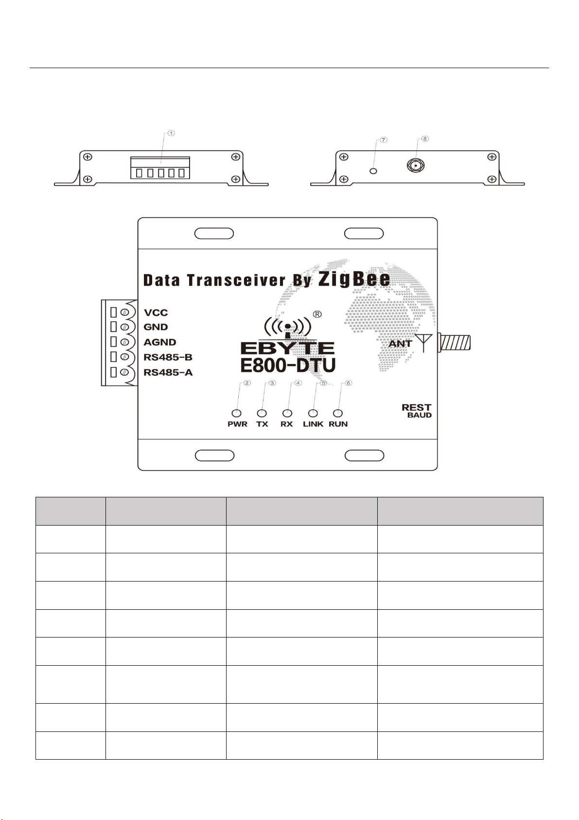
2.1 Pin description
Pin NO.
Name
Function
Description
1
3.81mm terminal block
UART interface/
Power supply interface
Standard RS-232&485 interface/
Screwing power supply interface
2
PWR-LED
Power LED
Red, lit when the power is on
3
TX-LED
Transmit LED
Yellow, blinks when sending data
4
RX-LED
Receive LED
Yellow, blinks when reveiving data
5
LINK-LED
Link LED
Red, lit when no network, off when
network connected
6
RUN-LED
Run LED
Red, system operating Indicator, lit
when running error, off when
running properly
7
Baud Rate Reset
Tact switch
Reset baud rate(115200)
8
Antenna interface
SMA-K interface
External thread, 10mm, 50Ω
characteristic impedance
Page 5

5
2.2 Dimension
Page 6
6
3. Interface definition
3.1 Power interface definition
Users can choose ① the VCC and GND terminal power supply, E800-DTU(Z2530-2G4-20) can use 8~ 28V DC power
supply, but it is recommended to use 12V or 24V DC power supply.
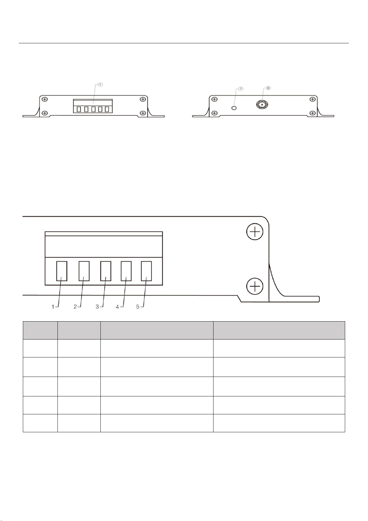
3.2 RS485 interface definition
E800-DTU(Z2530-2G4-20) uses RS485 as communication protocol. How to connect the cable? Choose the
corresponding interface in ① 3.81mm terminal block, details below:
Pin NO.
Definition
Function
Description
1
VCC
Screwing power interface, positive
8 ~ 28V DC, 12V or 24V( recommended )
2
GND
Screwing power interface, negative
The power supply negative pole is connected
to the system ground and the housing
3
AGND
Public ground
Connected to ground of other devices or not
connection
4
RS485-B
Serial port terminal
RS-485: Connected to RS 485 device interface B
5
RS485-B
Serial port terminal
RS-485: Connected to RS 485 device interface A
★ Note: The transceiver will be in poor communication when connecting multiple devices , while connecting a single
device is not, please try to parallel connect a 120Ω resistor between 485_A terminal and 485_B terminal.
Page 7

7
4. Function module
4.1. Operating mode
Mode
Node type
Description
Data communication
display mode
Mode 1
(Transparent
mode)
Coordinator
Serial data will be transmitted to modules not in sheep by broadcasting.
Data format can be
configured by command:
1 Display Mac address of
transmitter
2 Display Mac address of
transmitter
3 Display RSSI value of
message shortest path
(Display mode can be
configured to no display,
one mode display or
multiple modes display)
Router
Serial data will be transmitted to coordinators by point to point.
(Note: Terminal can not receive the data in sleep mode )
Terminal
Mode 2
(Half-transpa
rent mode)
Coordinator
Data will be transmitted according to the fixed format protocol of data
transmission, There are point to point, broadcast, multicast transmission
ways. Please refer to “HEX data communication description“ for details.
Router
Serial data will be transmitted to coordinators by point to point.
Terminal
Mode 3
(Protocol
mode)
Coordinator
Data will be transmitted according to the fixed format protocol of data
transmission, There are point to point, broadcast, multicast transmission
ways. Please refer to “HEX data communication description“ for details.
None
Router
Terminal
Note:User can only operate Mode 3 to configure GPIO function. Communication between arbitrary modes can communicate with each other
and not affect each other。
4.2 Brief introduction of protocol mode
No.
Mode
Description
1
Broadcast
User can broadcast on the whole network according to command when connecting network (3 modes):
1、Mode 1 ——Broadcast to all modules.
2、Mode 2 ——Broadcast to modules in the receiving mode (except sleep mode).
3、Mode 3 ——Broadcast to full function modules (Coordinator and Router).
2
Multicast
Multicast to all modules (not in sleep mode) when connecting network.
3
Point to
point
Module can communicate with other devices by short address according to command when connecting network (3
modes):
1、Transparent transmission ——no information
2、Short address ——the information is short address
3、Mac address ——the information is MAC address
Notes: Please refer to “HEX data communication description“ for details.
Page 8
8
5. Quick Start
★ Note: programming can only be carried on in a specific mode(see above), if fails, please confirm the work mode.
No.
Notes
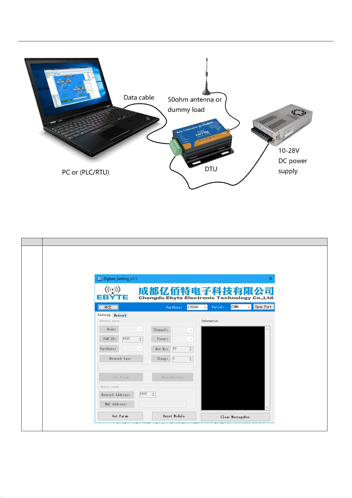
1
【Construct network】:
①.Connect Zigbee ad hoc module via USB to UART converter.
②.Open host computer software “Zigbee_Setting_V1.1”, select Com port and set baud rate as 115200(default), then
open port;
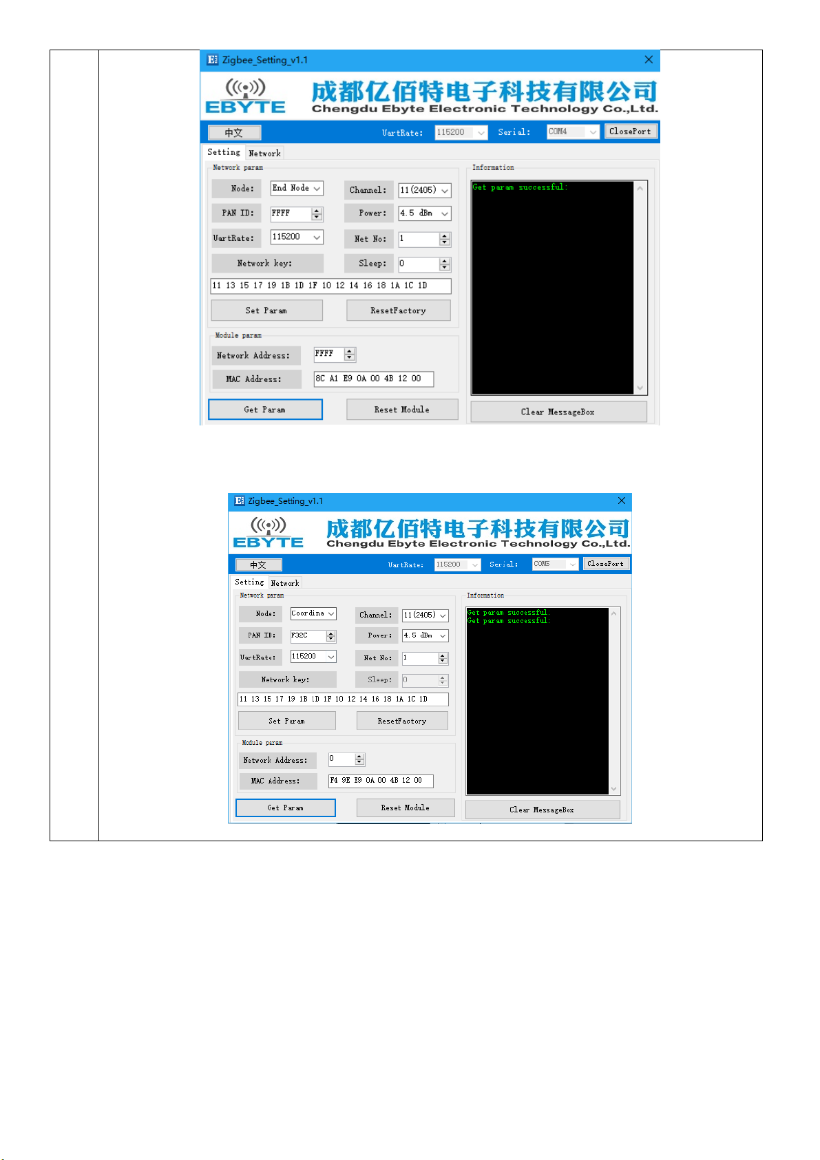
③.Click read parameter to read corresponding module parameter.
Page 9
9
④.Select node type as coordinator, write in parameter. Wait the coordinator to start constructing network and users can
check module parameter.
Set network parameter:(when PAN ID is FFFF, it is automatic PAN ID)
Read parameter when network is constructed:
Page 10
10
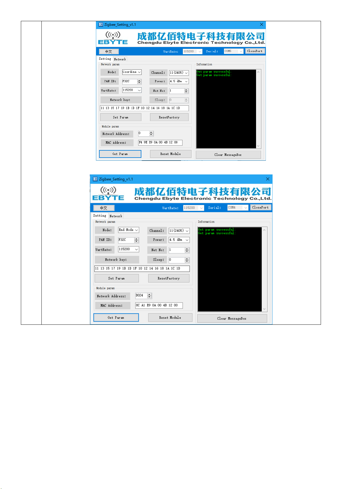
⑤.Select another module, set it as the router or end device following the same steps (module is set as end device when
leave factory (default),no need to set again, in this experiment it is end device )。
Page 11

11
2
【Communication test】:
①.Click “fixed networking”of the coordinator and end device of the host computer. Corresponding info. is available to be
viewed.
Coordinator:
End device:
②. For users’ convenience to observe, in this experiment it is HEX transmitting mode.
If the device address is unknown, please input corresponding mac address and click get network address. The short
address of coordinator is 0.
Page 12

12
③.Input random content in these 3 modes, click start.
Transparent transmission:
From coordinator to end device:
From end device to coordinator:
Network address:
From coordinator to end device:
Page 13

13
From end device to coordinator:
MAC address:
From coordinator to end device:
From end device to coordinator:
Multicast:
Page 14

14
Broadcast :( broadcast only conduct Mode 1, the entire network conduct broadcast mode experiment, other modes test
by themselves )
Data function transmission needs to reflect its own characteristics in the case of multi-node network, the users can test by
themselves!
6. User Command Set
For the convenience of users, E800-DTU(Z2530-2G4-20) has two command formats, AT and HEX, default HEX. In this mode, user
can transmit “+++” with serial port assistant to be in temporary AT command mode, then can configure with AT command and exit AT
command mode by transmitting “AT+EXIT”.
Note:
1. Serial data format error message
HEX command mode: F7 FF
AT command mode: +ERROR<CR><LF>
2. Coordinator building network message
HEX command mode: FF FF
AT command mode: Builded network<CR><LF>
3. Module joining the network message
HEX command mode: FF AA
AT command mode: Joined network<CR><LF>
4. Module no network message
HEX command mode: FF 00
AT command mode: No network<CR><LF>
5. <CR>: 0x0D
6. <LF>: 0x0A
Page 15

15
6.1 HEX command Set
Description
Format
Example
Read device type
Transmit:FE 01 01 FF
Return:FB dev_type
Transmit:FE 01 01 FF
Return:FB 02
Read network state
Transmit:FE 01 02 FF
Return:FB nwk_state
Transmit:FE 01 02 FF
Return:FB 01
Read network PAN_ID
Transmit:FE 01 03 FF
Return:FB pan_id
Transmit:FE 01 03 FF
Return:FB 02 F4
Read network key
Transmit:FE 01 04 FF
Return:FB key
Transmit:FE 01 04 FF
Return:FB 11 13 15 17 19 1B 1D 1F 10 12 14 16 18 1A 1C 1D
Read local short address
Transmit:FE 01 05 FF
Return:FB ShortAddr
Transmit:FE 01 05 FF
Return:FB F2 EF
Read local Mac address
Transmit:FE 01 06 FF
Return:FB Mac_Addr
Transmit:FE 01 06 FF
Return:FB 89 6C 50 09 00 4B 12 00
Read father node short
address
Transmit:FE 01 07 FF
Return:FB Coor_shortAddr
Transmit:FE 01 07 FF
Return:FB 00 00
Read father node Mac
address
FE 01 08 FF
Return:FB Coor _Mac_Addr
Transmit:FE 01 08 FF
Return:FB 20 39 EA 0A 00 4B 12 00
Read network group no.
Transmit:FE 01 09 FF
Return:FB group
Transmit:FE 01 09 FF
Return:FB 01
Read communication
channel
Transmit:FE 01 0A FF
Return:FB channel
Transmit:FE 01 0A FF
Return:FB 0B
Read transmission power
Transmit:FE 01 0B FF
Return:FB txpower
Transmit:FE 01 0B FF
Return:FB 04
Read serial baudrate
Transmit:FE 01 0C FF
Return:FB baud
Transmit:FE 01 0C FF
Return:FB 09
Read sleep state (vaild for
terminal)
Transmit:FE 01 0D FF
Return:FB sleep_time
Transmit:FE 01 0D FF
Return:FB 05
Read data storage time
(valid for router and
coordinator)
Transmit:FE 01 0E FF
Return:FB 1E
Transmit:FE 01 0E FF
Return:FB 1E
Read all datas
Transmit:FE 01 FE FF
Return:FB all_info
Transmit:FE 01 FE FF
Return:FB 02 01 02 F4 11 13 15 17 19 1B 1D 1F 10 12 14 16 18 1A
1C 1D F2 EF 89 6C 50 09 00 4B 12 00 00 00 20 39 EA 0A 00 4B 12
00 01 0B 04 09 05
Read arbitrary short
address of Mac address
Transmit:FE 09 10 Mac_Addr FF
Return:FB shortAddr
Transmit:FE 09 10 AF 99 E9 0A 00 4B 12 00 FF
Return:FB 08 35
Read remote /local GPIO
input/output state
Command:FE 04 20 addr gpiox
FF
Return:FB 20 addr In/Out
FE 04 20 F9 DE 04 FF
Read remote /local GPIO
input/output level
Command:FE 04 21 addr gpiox
FF
Return:FB 21 addr In/Out level
FE 04 21 FF FF 04 FF
Page 16

16
Description
Format
Example
Read remote /local PWM
state
Command:FE 04 22 addr 22 FF
Return:FB 22 addr period duty1
duty2 duty3 duty4 duty5
FE 04 22 FFFF 22 FF
Read remote /local ADC
state
Command:FE 04 23 addr pin FF
Return:FB 23 addr adc_value
FE 04 23 FF FF 01 FF
6.2 HEX Parameter Description
Network type
dev_type: 00 coordinator
01 router
02 terminal(default)
Network state
nwk_state: 00 no network
01 network
Network PAN_ID
pan_id: 0000~FFFE fixed network PAN_ID
FFFF random network PAN_ID
Network key
key: 16 bytes network key
Network short address
ShortAddr: 2 Byte address
Network MAC address
Mac_Addr: 8 Byte address
Father node short address
Coor_shortAddr:2 Byte address
Father node Mac address
Coor_Mac_Addr: 8 Byte address
Page 17

17
Network group no.
group: 1~99(default 1)
Network chananel
channel: 11~26(default 11)
Transmission power
txpower:
txpower contrast with PA / without PA
txpower
power (dBm)
txpower
power (dBm)
00
-3 / 16
03
2.5 / 20
01
-1.5 / 17
04
4.5 / 20 (default)
02
0 / 19 05
Serial baudrate
baud:
baudrate contrast
baud
baudrate
baud
baudrate
00
2400 08
76800
01
4800 09
115200(default)
02
9600 0A
128000
03
14400 0B
230400
04
19200 0C
256000
05
38400 0D
460800
06
43000 0E
921600
07
57600 0F
1000000
Sleep time
sleep_time: 0 sleep mode closed(default)
1~250 sleep mode opened sleep time is sleep_time /S (second)
Father node storage time
time: 0~120(default 30), unit S(second)
GPIO parameter
(1)GPIO port
gpiox:
Page 18

18
GPIO contrast
gpiox
00
01
02
03
04
05
06
07
08
09
GPIO
P0_0
P0_1
P0_2
P0_3
P0_4
P0_5
P0_6
P2_0
P2_1
P2_2
For example: When gpio parameter is 2,the pin is P0_2
When gpio parameter is 8,the pin is P2_1
(2)GPIO input/output state
in/out: 1 input
0 output
(3)GPIO state value(configuration input state invalid)
level: 0 low
1 high
2 flipping
PWM parameter
(1)PWM port
pwmx:
PWM port contrast
pwmx
duty1
duty2
duty3
duty4
duty5
GPIO
P0_2
P0_3
P0_4
P0_5
P0_6
(2)pwm cycle
period:(0~FFFF)
cycle tim(unit 1 = 62.5ns)
(3)pwm duty cycle
dutyx: (0~FFFF):
duty cycle time (unit 1 = 62.5ns)
ADC parameter
(1)ADC channel
adcx:
ADC channel contrast
adcx 0 1 2 3 4 5
6
GPIO
P0_0
P0_1
P0_2
P0_3
P0_4
P0_5
P0_6
(2)adc state value
adc_state: 0 ADC enable
1 ADC disable
(3)adc sampling value
adc_value: 0~0X0CE4 (0~3300)unit mV
Page 19

19
Peripherals addr parameter
(1)Peripherals address
addr:
FFFF inquire/configure local info
0~FFF8 inquire/configure info of whose network address is addr
FFFE、FFFD、FFFC inquire/configure info of which received broadcasting data
---FFFE broadcast to all modules
---FFFD broadcast to free modules(except sleeping modules)
---FFFC broadcast to coordinators and routers
All information
(1)all_info:
Identification ( Length (position) ) Description
dev_type (1 Byte(0) ) Device type
nwk_state (1 Byte(1) ) Network state
pan_id (2 Byte(2~3)) Network PAN_ID
key (16 Byte(4~20)) Network key
ShortAddr (2 Byte(21~22)) Network short address
Mac_Addr (8 Byte(23~30)) MAC address
Coor_shortAddr (2 Byte(31~32)) Father node short address
Coor_Mac_Addr (8 Byte(33~40)) Father node MAC address
group (1 Byte(41)) Network group no.
channel (1 Byte(42)) Communication channel
txpower (1 Byte(43)) Transmission power
baud (1 Byte(44)) Serial baudrate
sleep_time (1 Byte(45)) Sleep mode
Example for parameter:
all_info:
020102 F411 13 15 17 19 1B 1D 1F 10 12 14 16 18 1A 1C 1DF2 EF89 6C 50 09 00 4B 12 0000 0020 39 EA 0A 00 4B 12 00010B040905
➢ Device type: 02 (terminal)
➢ Network state: 01 (existing network)
➢ Network PAN_ID: 02 F4 (PAN_ID=0X02F4)
➢ Network key: 11 13 15 17 19 1B 1D 1F 10 12 14 16 18 1A 1C 1D
➢ Local short address: F2 EF (Local short Address=0XF2EF)
➢ Local MAC address: 89 6C 50 09 00 4B 12 00
➢ Father node short address: 00 00(Short Address=0X0000)
➢ Father node MAC address: 20 39 EA 0A 00 4B 12 00
➢ Network group no.: 01 (1)
➢ Communication channel: 0B (11)
➢ Transmission power: 04 (4.5dBm)
➢ Serial baudrate: 09 (115200)
➢ Sleep mode: 05 (5 seconds)
(Note:Father node storage time is not included,if needs inquire or configuration,please use independent command)
Page 20

20
HEX communication description
Command format description
(Note:It is applicable only to the nodes in mode 3 or coordinator in mode 2)
Command(COM)1Byte
Length(LEN)1Byte
Data(DATA)
FC
LEN
DATA
Parameter description
DATA parameter description:
(1)Broadcasting data(content to be sent)
command:01+type+data
parameter description:type
01:mode 1 ——broadcast to all modules
02:mode 2 ——broadcast to free modules(except sleeping modules)
03:mode 3 ——broadcast to coordinators and routers
e.g:FC 05 01 02 31 32 33
description:broadcasting HEX data in mode2:0X31 0X32 0X33
(2)Multicasting data(content to be sent)
command:02+ group+data
parameter description:group
0~99:number
e.g:FC 05 02 01 31 32 33
description:transmit HEX data to network group no.1:0X31 0X32 0X33
(3)Point to point transmission(content to be sent)
command:03+ type +addr+data
parameter description: type (for coordinator in mode 2,it’s invalid,it can be set to any value)
01:transparent transmission mode(no info.)
02:short address mode(short message info.)
03:MAC address mode(MAC message info.)
note:addr:network short address valid address: 0x0000—0xFFF8.
e.g:FC 07 03 01 AB CD 31 32 33
description:transmit HEX data point to point with short address to device whose network address is 0XADCD:0X31 0X32 0X33
AT Command Set
AT+DEV
Function:inquire /configure device type
Format:
inquire
transmit:AT+DEV= type
return:+OK<CR><LF>
configure
Page 21

21
transmit:AT+DEV=?
return:DEV= type<CR><LF>
Parameter: type
C coordinator
R router
E terminal
e.g:AT+DEV=C
Default:DEV=E
AT+EXIT
Function:exit temporary AT command(valid when pull low P1_6 pin to be in AT mode)
Format:
configure
transmit:AT+EXIT
return:+OK<CR><LF>
e.g:AT+EXIT
AT+MODE
Function:inquire /configure operating mode
Format:
Inquire
transmit:AT+MODE=?
return:MODE=type<CR><LF>
configure
transmit:AT+MODE=mode
return:+OK<CR><LF>
Parameter:mode
1 mode 1 (transparent transmission mode)
2 mode 2 (half transparent transmission mode)
3 mode 3 (protocol mode)
e.g:AT+MODE=3
default:MODE=3
AT+RMODE
Function:inquire /configure communication display mode
Format:
inquire
transmit:AT+RMODE=?
return:RMODE=type<CR><LF>
configure
transmit:AT+RMODE=type
return:+OK<CR><LF>
Paremeter: rmode(1 on 0 off ; value:0-7 )
Page 22

22
0bit :transmitter‘s Mac address’
1bit :transmitter‘s short address’
2bit :RSSI value of message shortest path
e.g:AT+RMODE=0
default:RMODE=0
AT+NWK
Function:inquire network state
Format:
inquire
transmit:AT+NWK=?
return:NWK=nwk_state<CR><LF>
Parameter:nwk_state
0 no network
1 existing network
e.g:AT+NWK=?
AT+PANID
Function:inquire /configure network PANID
Format:
inquire
transmit:AT+PANID=?
return:PANID=panid<CR><LF>
configure
transmit:AT+PANID=mode
return:+OK<CR><LF>
Parameter:panid
0000-FFFE fixed PANID
FFFF random PANID
e.g:AT+ PANID=0XA1B2
AT+KEY
Function:inquire /configure network key
Format:
inquire
transmit:AT+KEY=?
return:KEY=key<CR><LF>
configure
transmit:AT+PANID=mode
return:+OK<CR><LF>
Parameter:key
16 Byte network key
e.g:AT+ KEY=01030507090B0D0F00020406080A0C0D
Default:KEY=01030507090B0D0F00020406080A0C0D
Page 23

23
AT+SHORT_ADDR
Function:inquire /configure local network address
Format:
inquiry
transmit:AT+SHORT_ADDR =?
return:SHORT_ADDR=shortaddr<CR><LF>
Parameter:shortaddr
0000-FFFF network short address
e.g:AT+SHORT_ADDR=?
AT+MAC_ADDR
Function:inquiry/configure network PANID
Format:
inquiry
transmit:AT+MAC_ADDR=?
return:MAC_ADDR=macaddr<CR><LF>
Parameter:macaddr
8 Byte MAC address(unique IEEE ID)
e.g:AT+MAC_ADDR=?
AT+COOR_SHORT_ADDR
Function:inquiry father node network short address
Format:
inquiry
transmit:AT+COOR_SHORT_ADDR=?
return:COOR_SHORT_ADDR=macaddr<CR><LF>
Parameter:macaddr
8 Byte short address(unique IEEE ID)
e.g:AT+COOR_SHORT_ADDR=?
AT+COOR_MAC_ADDR
Function:inquiry father node network MAC address
Format:
inquiry
transmit:AT+COOR_MAC_ADDR=?
return:COOR_MAC_ADDR=macaddr<CR><LF>
Parameter:macaddr
8 Byte MAC address(unique IEEE ID)
e.g:AT+COOR_MAC_ADDR=?
AT+GET_SHORT_ADDR
Function:inquiry any MAC device short address
Page 24

24
Format:
inquiry
transmit:AT+GET_SHORT_ADDR=macaddr
return:GET_SHORT_ADDR=shoraddr<CR><LF>
Parameter:macaddr
8 Byte MAC address(unique IEEE ID)
shoraddrt
short address
e.g:AT+GET_SHORT_ADDR=4B805A3D25741200
AT+GROUP
Function:inquiry/configure network group no.
Format:
inquiry
transmit:AT+GROUP=?
return:GROUP=group<CR><LF>
configure
transmit:AT+GROUP=group
return:+OK<CR><LF>
Parameter:group(0~99)
Local group no.
e.g:AT+GROUP=group
Default:GROUP=1
AT+CH
Function:inquiry/configure communication channel
Format:
inquiry
transmit:AT+CH=?
return:CH=ch<CR><LF>
configure
transmit:AT+CH=ch
return:+OK<CR><LF>
Parameter:ch(11~26)
wireless channel
e.g:AT+CH=11
Default:CH=11
AT+TXPOWER
Function:inquiry/configure transmission power
Format:
inquiry
transmit:AT+TXPOWER=?
return:CH=txpower<CR><LF>
Page 25

25
configure
transmit:AT+TXPOWER=txpower
return:+OK<CR><LF>
Parameter:txpower(0~4)
transmission power
e.g:AT+TXPOWER=4
Default:TXPOWER=4
AT+UART
Function:inquiry/configure baudrate
Format:
inquiry
transmit:AT+UART=?
return:UART=baud<CR><LF>
configure
transmit:AT+UART=baud
return:+OK<CR><LF>
Parameter:baud(0~15)
serial baudrate
e.g:AT+UART=9
Default:UART=9
AT+SLEEP
Function:inquiry/configure sleep mode (valid for terminal)
Format:
inquiry
transmit:AT+SLEEP=?
return:SLEEP=sleep<CR><LF>
configure
transmit:AT+SLEEP=sleep
return:+OK<CR><LF>
Parameter:sleep
0 close sleep mode
1~250 open sleep mode,time is 1~250 seconds
e.g:AT+SLEEP=0
Default:SLEEP=0
AT+DATA_TIME
Function:inquiry/configure data storage time (valid for coordinator and router)
Format:
inquiry
transmit:AT+DATA_TIME=?
return:DATA_TIME=data_time<CR><LF>
configure
Page 26

26
transmit:AT+SLEEP=data_time
return:+OK<CR><LF>
Parameter:data_time
0~120 data storage time,unit: second
e.g:AT+DATA_TIME=30
Default:DATA_TIME=30
AT+SOFT_ID
Function:inquiry/configure soft id
Format:inquiry
transmit:AT+SOFT_ID=?
return:SOFT_ID=soft_id<CR><LF>
Parameter:soft_id
software id
e.g:AT+SOFT_ID=?
AT+RESET
Function:reset
Format:configure
transmit:AT+RESET
return:+OK<CR><LF>
e.g:AT+ RESET=?
AT+RESTORE
Function:restore factory settings
Format:configure
transmit:AT+RESTORE
return:+OK<CR><LF>
e.g:AT+RESTORE=?
AT+GPIO_PUT
Function:configure remote/local GPIO input/output mode
Format:configure
transmit:AT+GPIO_PUT=addr,gpiox,inout
return:+OK<CR><LF>
Parameter:addr
0000~FFF8 remote short address device
FFFF local device
gpiox (0~9)
GPIO port number
input
0 output state
1 input state
Page 27

27
e.g:AT+GPIO_PUT=1AC0,5,0
AT+RGPIO_PUT
Function:read remote/local GPIO input/output mode
Format:
configure
transmit:AT+RGPIO_PUT=addr,gpiox
return:RGPIO_PUT=addr,input<CR><LF>
Parameter:addr
0000~FFF8 remote short address device
FFFF local device
gpiox (0~9)
GPIO port number
input
0 output state
1 input state
e.g:AT+RGPIO_PUT=1AC0,5
AT+GPIO_LEVEL
Function:read remote/local GPIO input/output mode
Format:
configure
transmit:AT+GPIO_LEVEL=addr,gpiox,level
return:+OK<CR><LF>
Parameter:addr
0000~FFF8 remote short address device
FFFF local device
gpiox (0~9)
GPIO port number
level
0 high level
1 low level
2 flipping
e.g:AT+GPIO_LEVEL=1AC0,5,2
AT+RGPIO_LEVEL
Function:read remote/local GPIO input/output mode
Format:
read
transmit:AT+RGPIO_LEVEL=addr,gpiox
return:RGPIO_LEVEL=addr,input,level<CR><LF>
Parameter:addr
0000~FFF8 remote short address device
FFFF local device
Page 28

28
gpiox (0~9)
GPIO port number
input
0 output number
1 input number
level
0 high level
1 low level
e.g:AT+RGPIO_LEVEL=1AC0,5
AT+PWM
Function:configure remote/local GPIO input/output mode
Format:
configure
transmit:AT+PWM= addr,period,duty1, duty2,duty3,duty4,duty5
return:+OK<CR><LF>
Parameter:addr
0000~FFF8 remote short address device
FFFF local device
period (unit 1 = 62.5ns)
0~65535 cycle
duty1
0 closed
other channel 1 square wave of 50% duty cycle
duty2~ duty5 (0~65535 unit 1 = 62.5ns)
the positive pulse duration of the corresponding channel, PWM is closed when it is 0 or greater than the cycle
e.g:AT+ PWM=1AC0,1000,1,500,500,0,500
AT+RPWM
Function:read remote/local PWM input/output mode
Format:
read
transmit:AT+RPWM=addr
return:RPWM=addr,period,duty1,duty2,duty3,duty4,duty5<CR><LF>
Parameter:addr
0000~FFF8 remote short address device
FFFF local device
period (unit 1 = 62.5ns)
0~65535 cycle
duty1
0 closed
other channel 1 square wave of 50% duty cycle
duty2~ duty5 (0~65535 单位 1 = 62.5ns)
the positive pulse duration of the corresponding channel, PWM is closed when it is 0 or greater than the cycle
e.g:AT+RPWM=1AC0
Page 29

29
AT+ADC
Function:read remote/local ADC input amount
Format:
read
transmit:AT+ADC=addr,adcx
return:ADC=addr,val<CR><LF>
Parameter:addr
0000~FFF8 remte short address device
FFFF local device
adcx (0~6)
ADC channel
val (0~3300)
current acquisition voltage value,unit: mV
e.g:AT+ADC=1AC0,5
7. User Instruction
7.1.Network role and notice
No.
Description
1
Module uses Zigbee ad hoc networking, consisting of one coordinator and random other devices(routers and
end-devices)
2
It has self-organization, self-routing and network multi-hopping function (By default the network depth is 5, there
are 20 son nodes and 6 son router nodes in total)
3
The father node device (coordinator and router) can save data for the end-devices in sleep. The save time can be
set by the user (by default it is 30 seconds, ranging from 0 to 120 seconds).
4
Only the end device has the sleep function, sleeping within 250S, the user can set by themselves, the default 0 (with
sleep mode off).
Note: The recommended sleep time must be less than the data storage time of father node , otherwise it will affect
the data reception.
5
In network communication Short Address communication is used.
Note: The short address is randomly distributed when the device joins the network, the long address of MacAddress
is the only fixed one, if the short address is unknown, the network Short Address can be found via corresponding
commands according to the MacAddress , and point to point communication is conducted.
6
Coordinator is unique in the network, the short address is 0000.
7
If unicast address is FFFF,FFFD,FFFC,then it corresponds to three broadcast mode.
8
When PANID is FFFF, it means automatic distribution. Networking can not be realized if PANID is different.
Page 30

30
9
When network keys are not the same the network can not be joined. The module network key of the module
remains open, the user can not get the correct air data via software packet capture .
10
All devices in the network have opened broadcast function. Multiple devices broadcasting at the same time or a
single device broadcasting at a higher frequency will lead to a serious network congestion. Please try to avoid this
situation.
11
When multicasting module does not need to join the group,but be directly multicasted to any group according to
communication usage guidance. After the multicast, the local group number will not change due to different
multicast number.
12
PWM function and sleep mode can not be used at the same time in network, please turn off the sleep mode before
turn on PWM function .
13
After sleep mode, it can be waked up via the serial port(UART).
Note: In the sleep state, the first frame of data waked up via UART is invalid.
14
In the Zigbee network, single package data transmission can not be too fast(recommended more than 1s), because
the data may be lost. (Note, it may cause network instability when the nodes is too many and transmission is too
fast )
Notes:see more in <Zigbee setting software instruction>
7.2.Network structure
The network structure of module is MESH network
MESH network topology network has a powerful function, the network can communicate via "multi-level hopping"; the
topology can also form a ver y complex network; network also has self-organization, self-healing function.
Network structure diagram
Page 31

31
8. Practical application Fields
The data transceiver of CDEBYTE is applied for all kinds of point to point, one point to multiple points wireless data
transmission system, such as smart home, Internet of things transformation, power load monitoring, distribution network
automation, hydrological and hydrological forecasting, water pipe network monitoring, urban street lamps Monitoring, air
defense alarm control, railway signal monitoring, centralized control of railway water supply, oil supply pipe network
monitoring, GPS system, remote meter reading, electronic crane, automatic reporting, seismic forecasting, fire prevention,
environmental monitoring and other industrial automation system, as shown below:
Page 32

32
9. Note
1. Please keep the warranty card of the equipment which includes the factory number (and important technical
parameters) and is important for user's future maintenance and new equipment.
2. Transceiver during the warranty period, if the quality of the product itself rather than man-made damage or
lightning and other natural disasters caused by damage, enjoys free warranty; please do not repair by yourself, the
problem and please contact with our company when problem occurring, we offer the first-class after-sales service.
3. Please do not operate the transceiver in some flammable places such as coal mines or near explosive atmospheres
(such as detonators).
4. Please use the appropriate DC power supply, high frequency interference ability, small ripple, and enough load
capacity are required; it’s better to have over current, over voltage protection and lightning protection and other functions
to ensure that transceiver working properly.
5. Please do not use it in the working environment beyond the transceiver environmental characteristics, such as high
temperature, humidity, low temperature, strong electromagnetic fields or dust larger environment.
6. Please do not continuously keep transceiver to transmit in full capacity, or the transmitter might be damaged.
7. Please connect the ground with the external ground of the power supply (such as PC, PLC, etc.), otherwise it is easy
to burn out the communication interface; do not plug the interface with power supplying.
8. When testing, please connect the antenna or 50 Ω load, otherwise transceiver will be damaged easily ;the
distance from the antenna is better than 2 meters, so as to avoid harm, please do not touch the antenna when
transmitting.
9. Wireless data transceiver has different communication distance in different environments, communication distance
is influenced by temperature, humidity, obstacle density, obstacle volume and electromagnetic environment; in order to
ensure stable communication, it is recommended to reserve at least 50 % of the communication distance.
10. When communication distance is not perfect, it is recommended to improve the antenna quality and the
installation mode of the antenna. You can send mail to support@cdebyte.com for support.
11. When choosing power supply, it is recommended to keep at least 50% current left and the ripple must not exceed
100mV.
Page 33

33
10. Important statement
1. CDEBYTE reserves the right of final interpretation and modification of all the contents of this manual.
2. As the hardware and software products continuously improving, this manual may subject to change without notice,
please refer to the latest version.
3. Everyone is responsible for protecting the environment: to reduce the use of paper, we only provide electronic
documents of the English manual, if necessary, please go to our official website to download; In addition, for special
requirements, we agree to offer certain amount of documents according to order quantity, not every data transceiver are
supplied with one manual, please understa
CDEBYTE after-sales technical support: support@cdebyte.com
For file download and more product information, please visit:www.cdebyte.com/en/
Thank you for using the CDEBYTE products! Any questions or suggestions, please contact: support@cdebyte.com
Tel:+86-28-61399028
Fax:028-64146160
Web:www.cdebyte.com/en/
Address:Innovation Center D347, 4# XI-XIN Road,Chengdu, Sichuan, China
ISO9001:2008 ISO14001:2004
CDEBYTE reserves the right of final interpretation and modification of all the contents in this manual.
 Loading...