

Page 1
EBYTE Wireless Data Transceiver
E90-DTU
User Instruction Manual
This manual may change with the continuous improvement of the product. Please refer to the latest version of the instruction.
Chengdu Ebyte Electronic Technology Co., Ltd. reserves all rights of final interpretation and modification of this manual.
Page 2
1.Introduction
1.1 Brief introduction
E90-DTU is a wireless data transceiver with the function of digital data processing, digital modulation and
demodulation, FEC, balanced soft decision, etc.. Wireless data transceiver provides transparent RS232 / RS485 interface,
different with the analog FM transceiver plus MODEM analog digital transceiver.
Wireless data transceiver working as a communication medium,as well as the fiber, microwave, the same line, has a
certain scope of application: it provides some special conditions in the private network monitoring signal real-time, reliable
data transmission,with the features of low cost, convenient installation and maintenance , diffraction ability, flexible
network structure, range of coverage,suitable for the occasion of dot and scatter ,complex geographical environment ,
connecting with PLC, RTU, rain gauge, level gauge and other data terminals.
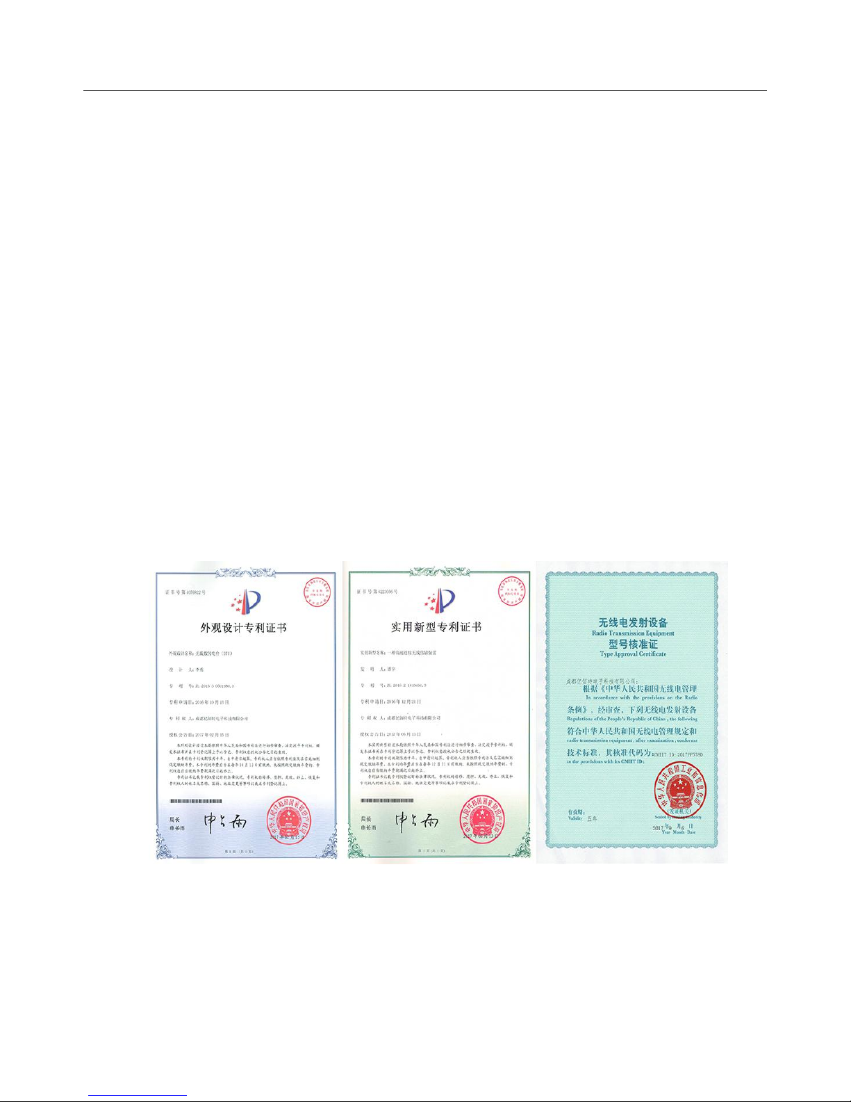
1.2 Certificate
E90-DTU has been issued the "Wireless Transmission Equipment Model Approval Certificate"by the Ministry of
Information Industry of China , the approval code: CMIIT ID: 2017FP5780.
E90-DTU has been issued the "Design Patent Certificate" by the State Intellectual Property Office of China, the patent
number: ZL 2016 3 0501980.3.
E90-DTU has been issued the"Utility Model Patent Certificate"by the State Intellectual Property Office of China, the
patent number: ZL 2016 2 1410691.3.
Page 3

1.3 Features
All the core components are imported originally , compared with the current imports of digital transceiver , we are
the most advanced, most cost effective and the smallest one.
Transmission power is optional:0.5 ~ 5W, all technical indicators have met the European industry standards.
Use temperature compensation circuit, the frequency stability is better than±1.5PPM.
With operating temperature range: -40℃~ +70℃, adapting to a variety of harsh working environment.
All with aluminum alloy shell, compact, easy installation, good heat dissipation; perfect shielding design, good
electromagnetic compatibility and strong anti-interference ability.
Power reverse protection, over-protection, antenna surge protection and other multiple protection functions,
greatly increase the reliability of the transceiver.
Powerful software features, all parameters can be programmed to set: such as power, frequency, air data rate,
address ID, etc.
Ultra-low power consumption, standby current is 50mA (the power consumption of power saving mode and sleep
mode is lower), the transmitting current≤1.2A (5W).
With watchdog and accurate time layout, in the event of an exception, the module will automatically restart and
continue to follow the previous parameters to operate.
Page 4

2.Dimension
2.1 Pin description
Pin NO.
Name
Function
Description
1
DB-9 female socket
RS-232 interface
Standard RS-232 interface
2
3.81 terminal block
RS-485, power interface
Standard RS-485 interface and
pressure line power interface
3
PWR-LED
Power LED
Red, lit when the power is on
4
TXD-LED
Transmit LED
Yellow, blinks when sending data
5
RXD-LED
Receive LED
Yellow, blinks when sending data
6
DC power interface
Power interface
In-line round hole, outer diameter
5.5mm, diameter 2.5mm
7
DIP switch
DIP switch
Controlled by working mode
8
Antenna interface
SMA-K interface
external thread, 10mm, 50
Ω
characteristic impedance
Page 5
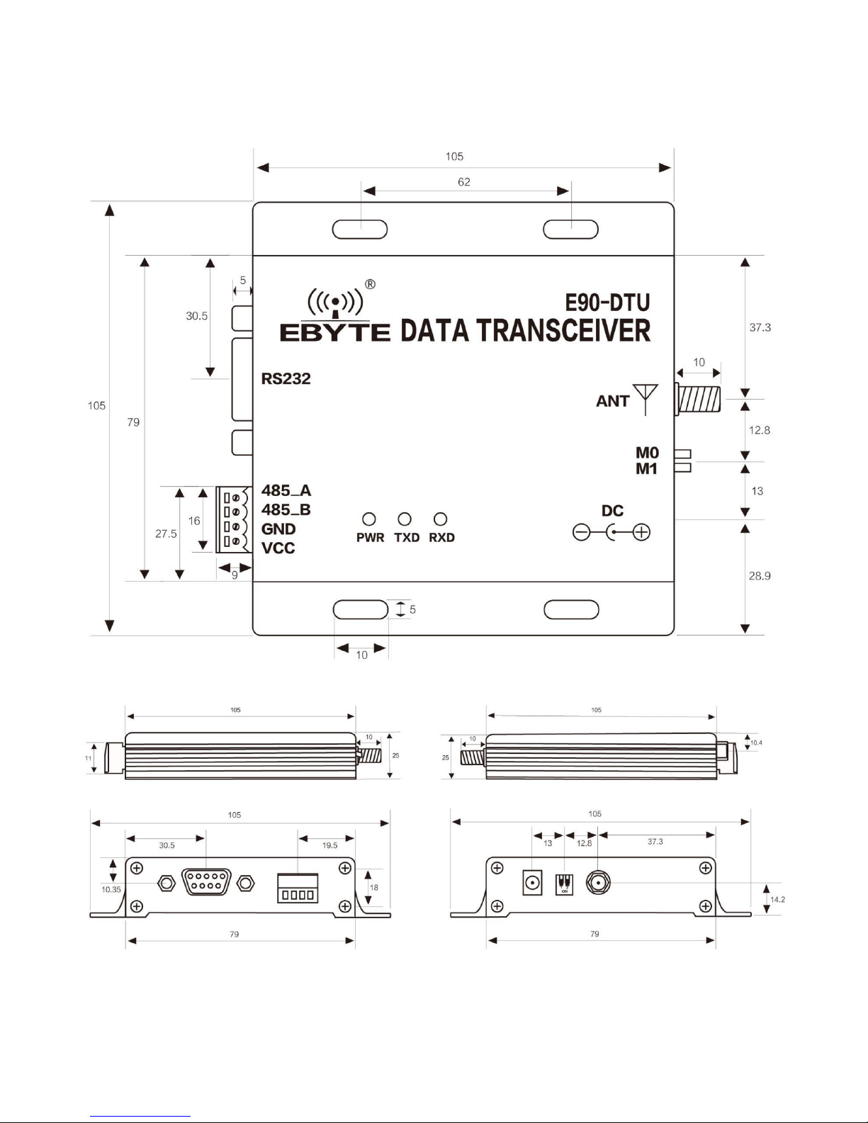
2.2 Type A dimension(L433-37, N230-37, C433-37)
★Note: Type A is the 5W power specification model, including the following models:L433-37, N230-37, C433-37
Page 6

2.3 Type B dimension(L433-30, L170-30, N230-27, N230-33, C433-30)
★
Note: Type B is below 2W power specifications models, including the following models: L433-30, L170-30, N230-27,
N230-33, C433-30
Page 7

3.Interface definition
3.1 Power interface definition
Users can choose
⑥
DC power interface,using the power adapter supply with the interface of the 5.5mm outer
diameter , 2.5mm diameter ;
Also choose the VCC and GND terminal power supply, only choose any one of the power supply is OK;
E90-DTU can use 10 ~ 28V DC power supply, but it is recommended to use 12V or 24V DC power supply.
3.2.RS232 interface definition
The E90-DTU can be connected to the device via RS-232 using the standard DB-9 interface.
3.3.RS485 interface definition
E90-DTU can connect the 485_A terminal and 485_B terminal with the device RS-485 A terminal and B terminal.
Pin NO.
Definition
Function
Description
1
VCC
Pressure line power interface, positive
10 ~ 28V DC, recommended 12V or 24V
2
GND
Pressure line power interface, negative
The power supply negative pole is connected
to the system ground and the housing
3
485_B
RS-485 interface, interface B
The RS-485 interface B is connected to the
device interface B
4
485_A
RS-485 interface, interface A
The RS-485 interface A is connected to the
device interface A
★
Note: The transceiver will be poor communication when connecting multiple devices , while connecting a single device
is not, please try to parallel connect 120Ωresistor between 485_A terminal and 485_B.
Page 8

4.Technical indicators
4.1 Model specifications
Series
Model
Frequency
(HZ)
Transmit
power(W)
Distance
(Km)
Specifications
Application
L
L433-30
433M18
LoRa spread spectrum,
anti - interference
To the environment with
small data, far distance
L433-37
433M520
LoRa spread spectrum,
anti - interference
To the environment with
small data, far distance
L170-30
170M18
LoRa spread spectrum,
anti - interference
To the environment with
small data, many obstacles
N
N230-27
230M
0.5
5
Super diffraction
capability
To the complex environment
with many obstacles
N230-33
230M28
Super diffraction
capability
To the complex environment
with many obstacles
N230-37
230M515
Super diffraction
capability
To the complex environment
with many obstacles
C
C433-30
433M13
High speed continuous
transmission
To the environment large
data supporting Modbus
C433-37
433M510
High speed continuous
transmission
To the environment large
data supporting Modbus
★ Note: Test condition: in clear and open air without shelters, 12V /2A power supply, 5dBi gain sucker antenna over 2
meters height from the ground, with the factory default parameters.
4.2 General specification parameters
NO.
Model
Specification
Description
1
Size(H*W*D)
82 * 62 * 25 mm
L433-30/L170-30/N230-27/N230-33/C433-30
124 * 105 * 25 mm
L433-37/N230-37/C433-37
2
Weight
130g
L433-30/L170-30/N230-27/N230-33/C433-30
240g
L433-37/N230-37/C433-37
3
Temperature
-40
℃~
+70
℃
-
4
Antenna impedance
50
Ω
Standard 50
Ω
characteristic impedance
5
Supply voltage
+10 ~ +28V DC
It is recommended to use 12V or 24V
6
Communication interface
RS232/RS485
Standard DB9 hole / 3.81 terminal block
7
Baud rate
Default 9600
from 1200 to 115200 bps
8
Address
Default 0
65536 configurable addresses
Page 9

4.3 Frequency range and channels
Series
Model
Default frequency(HZ
)
Frequency range(HZ
)
Channel spacing(HZ
)
Channels
L
L433-30
433M
410~441M
1M
32,half duplex
L433-37
433M
410~441M
1M
32,half duplex
L170-30
170M
160~173.5M
250K
55,half duplex
N
N230-27
230M
225~237.6M
200K
64,half duplex
N230-33
230M
225~237.6M
200K
64,half duplex
N230-37
230M
225~237.6M
200K
64,half duplex
C
C433-30
433M
425~450.5M
100K
256,half duplex
C433-37
433M
425~450.5M
100K
256,half duplex
★ Note: In the same area when multiple data transceivers are communicating one to one at the same time , it is
recommended to set the channel spacing between each group of data transceivers at 2MHz or more.
4.4 Transmit power level
Series
Model5W2W
1W
500mW
250mW
125mW
64mW
L
L433-30
√
Default
√√√
L433-37
√
Default
L170-30
√
Default
√√√
N
N230-27
√
Default
√√√
N230-33
√
Default
√√√
N230-37
√
Default
C
C433-30
√
Default
√√√
C433-37
√
Default
★ Note: The lower the transmit power, the closer the transmission distance, but the working current won’t be declined in
exact proportion , it is recommended to use the maximum transmit power.
Page 10

4.5 Air data rate
Series
Model
Default air data rate
(bps)
Levels
Air data rate(bps)
L
L433-30
2.4k
6
0.3,1.2,2.4,4.8,9.6,19.2k
L433-37
2.4k
6
0.3,1.2,2.4,4.8,9.6,19.2k
L170-30
2.4k
6
0.3,0.6,1.2,2.4,4.8,9.6k
N
N230-27
1.2k
8
1.2,2.4,4.8,9.6,19.2,38.4,50,70k
N230-33
1.2k
8
1.2,2.4,4.8,9.6,19.2,38.4,50,70k
N230-37
1.2k
8
1.2,2.4,4.8,9.6,19.2,38.4,50,70k
C
C433-30
N/A
N/A
Not adjustable, automatically adapt to the baud
rate
C433-37
N/A
N/A
Not adjustable, automatically adapt to the baud
rate
★
Note: The higher the air data rate, the faster the transmission rate, the transmission distance is also closer; when the
rate meets the requirements , the lower air data rate, the better quality .
4.6 Current parameters
Series
Model
Transmitting current(mA)
Standby current(mA)
12V
24V
12V
24V
L
L433-30
367
1822112
L433-37
1138
5585027
L170-30
293
1462213
N
N230-27
1638417
10
N230-33
806
3961911
N230-37
1037
5064122
C
C433-30
308
1542313
C433-37
1027
5074725
★
Note: It is recommended to retain more than 50% of the current margin when selecting the power supply, which will
help the data transceiver to work steadily for a long time.
Page 11

4.7. Transceiver Length and Sub-packing Mode
Series
Model
Buffer
Sub-package
L
L433-30
512 bytes
Automatically send 100 bytes per package
L433-37
512 bytes
Automatically send 100 bytes per package
L170-30
512 bytes
Automatically send 100 bytes per package
N
N230-27
512 bytes
Automatically send 100 bytes per package
N230-33
512 bytes
Automatically send 100 bytes per package
N230-37
512 bytes
Automatically send 100 bytes per package
C
C433-30
Unlimited single input (baud rate≤57600)
Continuous transmission without sub-package
C433-37
Unlimited single input (baud rate ≤57600)
Continuous transmission without sub-package
★ Note:
1. When the receiving data is more than a single packet capacity (100 bytes), the beyond part will be automatically
assigned to the second transmission until it is completed;
2. The data transceiver can not receive data which is more than the buffer capacity;
3. If one can not determine the amount of data sent and received, it is recommended to use C series.
5.Operating mode
E90-DTU has four operating modes, if low power consumption is not required, normal communication is
recommended to configure the data transceiver for the normal mode (mode 0);
The factory default is normal mode (mode 0).
5.1.L series and N series
Categories
M1
M0
Description
Mode 0
Normal Mode
ON
ON
Open UART and RF,transparent transmission is on
Mode 1
Wake-up Mode
ON
OFF
Air wake-up mode, the packet comes with a
wake-up code,
Mode 2
Power-saving Mode
OFF
ON
The air wake-up receive mode, saving receive
power, the mode can not be transmitted
Mode 3
Sleep Mode
OFF
OFF
Parameter setting using the configuration
software
★ Note: no need to care about the wake-up mode (mode 1) and power saving mode (mode 2) if it doesn’t request low
power consumption.
Page 12

5.2 C series
Categories
M1
M0
Description
Mode 0
Normal Mode
ON
ON
Open UART and RF,transparent transmission is on
Mode 1
Wake-up Mode
ON
OFF
UART and RF are closed
Mode 2
Command Mode
OFF
ON
Parameter setting using the configuration
software
Mode 3
Sleep Mode
OFF
OFF
Enter sleep mode, UART and module are closed
6.Connection diagram when programming
Series
Mode
M1
M0
Description
L
Sleep Mode
OFF
OFF
Only be programmed using the configuration
software in the current mode
N
Sleep Mode
OFF
OFF
Only be programmed using the configuration
software in the current mode
C
Command Mode
OFF
ON
Only be programmed using the configuration
software in the current mode
★ Note: programming can only be carried on in a specific mode(see above), if fails, please confirm the work mode.
Page 13

7.Connection diagram in test and practical application
8.Practical application
The data transceiver of CDEBYTE is applied for all kinds of point to point, one point to multiple points wireless data
transmission system, such as smart home, Internet of things transformation, power load monitoring, distribution network
automation, hydrological and hydrological forecasting, water pipe network monitoring, urban street lamps Monitoring, air
defense alarm control, railway signal monitoring, centralized control of railway water supply, oil supply pipe network
monitoring, GPS system, remote meter reading, electronic crane, automatic reporting, seismic forecasting, fire prevention,
environmental monitoring and other industrial automation system, as shown below:
Page 14

9.Note
1. Please keep the warranty card of the equipment which includes the factory number (and important technical
parameters) and is important for user's future maintenance and new equipment .
2. Transceiver during the warranty period, if the quality of the product itself rather than man-made damage or
lightning and other natural disasters caused by damage, enjoys free warranty; please do not repair by yourself, the
problem and please contact with our company when problem occurring , we offer the first-class after-sales service.
3. Please do not operate the transceiver in some flammable places such as coal mines or near explosive atmospheres
(such as detonators).
4. Please use the appropriate DC power supply, high frequency interference ability, small ripple, and enough load
capacity are required; it’s better to have over current, over voltage protection and lightning protection and other functions
to ensure that transceiver working properly.
5. Please do not use it in the working environment beyond the transceiver environmental characteristics , such as
high temperature, humidity, low temperature, strong electromagnetic fields or dust larger environment.
6. Please do not continuously keep transceiver to transmit in full capacity, or the transmitter might be damaged.
7. Please connect the ground with the external ground of the power supply (such as PC, PLC, etc.) , otherwise it is
easy to burn out the communication interface; do not plug the interface with power supplying.
8. When testing, please connect the antenna or 50 Ω load, otherwise transceiver will be damaged easily ;the
distance from the antenna is better than 2 meters, so as to avoid harm, please do not touch the antenna when
transmitting.
9. Wireless data transceiver has different communication distance in different environments , communication
distance is influenced by temperature, humidity, obstacle density, obstacle volume and electromagnetic environment; in
order to ensure stable communication, it is recommended to reserve at least 50 % of the communication distance.
10. When communication distance is not perfect, it is recommended to improve the antenna quality and the
installation mode of the antenna. You can send mail to support@cdebyte.com for support.
11. When choosing power supply, it is recommended to keep at least 50% current left and the ripple must not exceed
100mV.
Page 15

10.Important statement
1. CDEBYTE reserves the right of final interpretation and modification of all the contents of this manual.
2. As the hardware and software products continuously improving, this manual may subject to change without notice,
please refer to the latest version.
3. Everyone is responsible for protecting the environment: to reduce the use of paper, we only provide electronic
documents of the English manual, if necessary, please go to our official website to download; In addition, for special
requirements, we agree to offer certain amount of documents according to order quantity , not every data transceiver are
supplied with one manual, please understand;
CDEBYTE after-sales technical support: support@cdebyte.com
For file download and more product information, please visit:www.cdebyte.com/en/
Thank you for using the CDEBYTE products! Any questions or suggestions, please contact: support@cdebyte.com
Tel:+86-28-61399028
Fax:028-64146160
Web:www.cdebyte.com/en/
Address:Innovation Center D347, 4# XI-XIN Road,Chengdu, Sichuan, China
ISO9001:2008 ISO14001:2004
CDEBYTE reserves the right of final interpretation and modification of all the contents in this manual.
 Loading...