

Page 1

Chengdu Ebyte Electronic Technology Co.,Ltd E821-RTU
E821-RTU(0400-ETH) User Manual
(0400-ETH)User Manual
Page 2

Chengdu Ebyte Electronic Technology Co.,Ltd E821-RTU (0400-ETH)User Manual
11
Contents
Features...................................................................................................................................................................................3
1. Quick start...........................................................................................................................................................................4
1.1 Port Connection........................................................................................................................................................4
1.1.1 RS485 connection......................................................................................................................................... 4
1.1.2 Analog input connection............................................................................................................................... 4
1.2 Basic operation......................................................................................................................................................... 5
1.2.1 RS485 Bus control........................................................................................................................................ 5
1.2.2 Ethernet control.............................................................................................................................................7
2. Product description............................................................................................................................................................. 9
2.1 Basic parameters...................................................................................................................................................... 9
2.2 Size and Interface description................................................................................................................................ 10
2.3 Reset button description......................................................................................................................................... 12
3. Modbus............................................................................................................................................................................. 13
3.1 Register Address Table................................................................................................................................................... 13
3.2 Modbus address table..................................................................................................................................................... 14
3.3 RS485 serial port baud rate code value table..................................................................................................................14
3.4 RS485 serial port parity bit value table.......................................................................................................................... 14
3.5 Configure parameters by setting software...................................................................................................................... 15
4. Product Function...............................................................................................................................................................16
4.1 Working mode................................................................................................................................................................ 16
4.1.1 Slave mode..................................................................................................................................................16
4.1.2 Master mode................................................................................................................................................16
4.2 RTU basic function......................................................................................................................................................... 17
4.2.1 Read analog-data AI input.......................................................................................................................... 17
4.2.2 Analog AI acquisition range setting........................................................................................................... 18
4.3 Network related functions...............................................................................................................................................18
4.3.1 Device MAC address reading..................................................................................................................... 18
4.3.2 Device SN code reading..............................................................................................................................19
4.3.3 Network function parameter validation command (Ethernet restart command)........................................ 19
4.3.4 WAN port IP info configuration................................................................................................................. 20
4.3.5 Set DNS...................................................................................................................................................... 20
4.3.6 Set network protocol parameters................................................................................................................ 21
4.3.7 Set the registration package mode.............................................................................................................. 22
4.3.8 Set the registration package contents..........................................................................................................22
4.3.9 Set heartbeat package mode........................................................................................................................23
4.3.10 Set heartbeat package content...................................................................................................................24
4.3.11 Set heartbeat package time........................................................................................................................24
4.3.12 Clear the cache.......................................................................................................................................... 25
4.3.13 Set keep-alive parameters......................................................................................................................... 25
4.3.14 Set local port number................................................................................................................................ 26
4.3.15 Set cloud transparent transmission function............................................................................................. 27
4.3.16 Set timeout restart time............................................................................................................................. 27
Copyright ©2012–2019, Chengdu Ebyte Electronic Technology Co.,Ltd
Page 3

Chengdu Ebyte Electronic Technology Co.,Ltd E821-RTU (0400-ETH)User Manual
22
Important Statement..............................................................................................................................................................28
Reversion History................................................................................................................................................................. 28
About Us...............................................................................................................................................................................28
Copyright ©2012–2019, Chengdu Ebyte Electronic Technology Co.,Ltd
Page 4

Chengdu Ebyte Electronic Technology Co.,Ltd E821-RTU (0400-ETH)User Manual
33
Features
Support 4 analog inputs, default current acquisition;
Support Ethernet port, you can use socket to connect to remote server, support TCP/UDP;
Support Modbus TCP/RTU protocol;
Support Ebyte Cloud, can be controlled by commands;
Support 2 working modes, master mode and slave mode, slave can cascade multiple devices by RS485;
Support Reload touch button, long press for 5s, Modbus device address, RS485 serial port baud rate and check digit
will restore factory settings;
Hardware watchdog with high reliability;
Multiple indicators to show device working status;
The power supply has static and surge level 3 protection, and has over-current, over-voltage, anti-reverse and other
protections.
Note: Support customization of functions, such as conditional control (how to output based on input state)
Copyright ©2012–2019, Chengdu Ebyte Electronic Technology Co.,Ltd
Page 5
Chengdu Ebyte Electronic Technology Co.,Ltd E821-RTU (0400-ETH)User Manual
4
1. Quick start
This chapter is a quick introduction to E821-RTU (0400-ETH). It is recommended that users carefully read this
chapter and follow the instructions before using the product. It will have a systematic understanding of the product, and
users can also choose the one you are interested in according to your needs. For specific details and instructions, please
refer to the following sections.
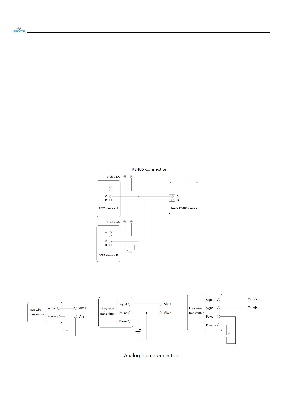
1.1 Port Connection
1.1.1 RS485 connection
The E821-RTU device has a master-slave mode and can be cascaded by the RS485 port.
Note: 120R (matching resistor) is added and not added according to the actual line matching (default is not added).
1.1.2 Analog input connection
Copyright ©2012–2019, Chengdu Ebyte Electronic Technology Co.,Ltd
Page 6
Chengdu Ebyte Electronic Technology Co.,Ltd E821-RTU (0400-ETH)User Manual
55
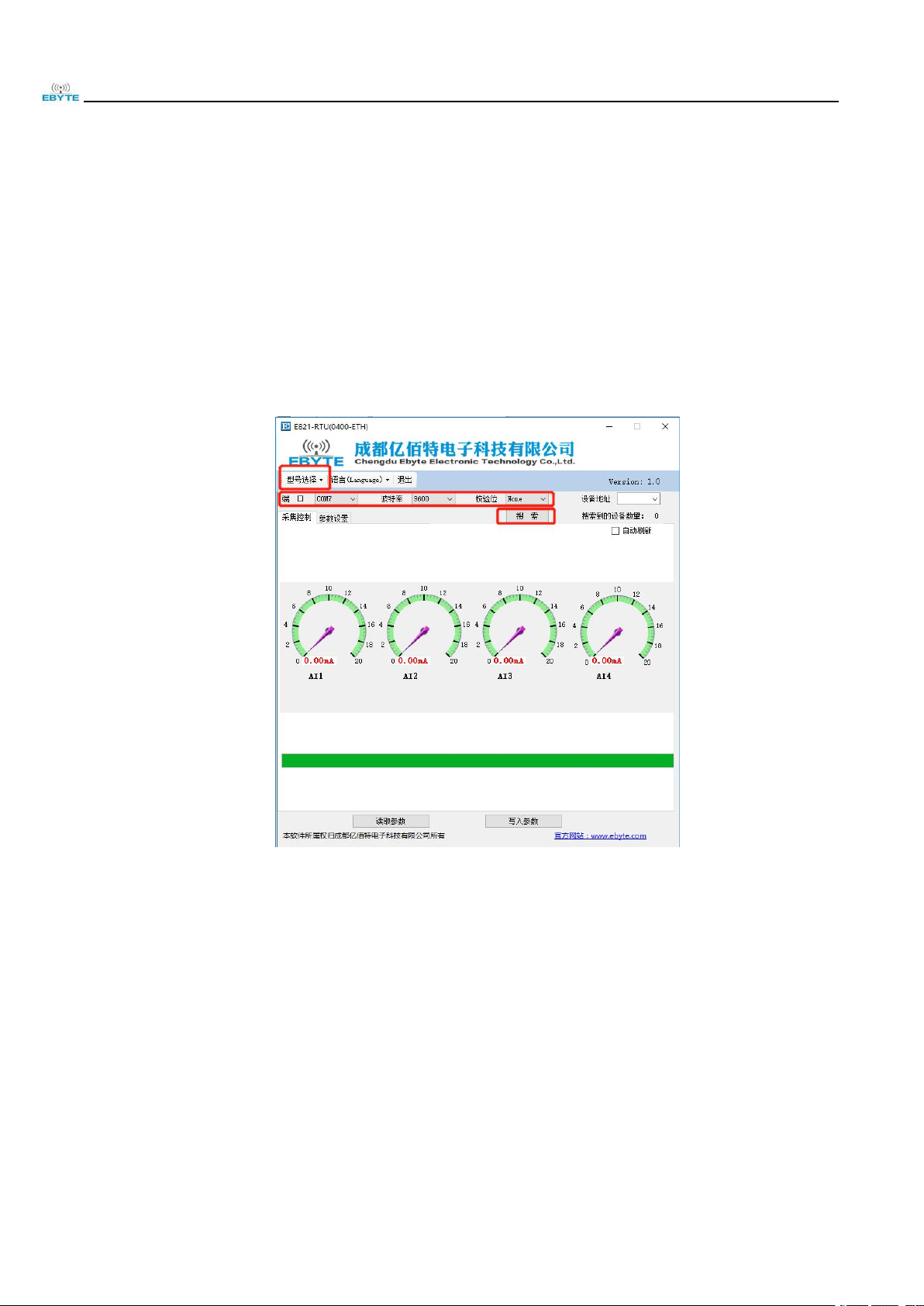
1.2 Basic operation
Connection: The computer connects to E821-RTU (0400-ETH) by USB to RS485 cable or the computer connects to
E821-RTU (0400-ETH) by Ethernet cable.
Power supply: E821-RTU (0400-ETH) working voltage is DC 8~28V, and the power supply has at least 0.2A power
supply capability.E821-RTU(0400-ETH).
1.2.1 RS485 Bus control
Select the device model, port number, set the baud rate check, and click “Search” to search for the device.
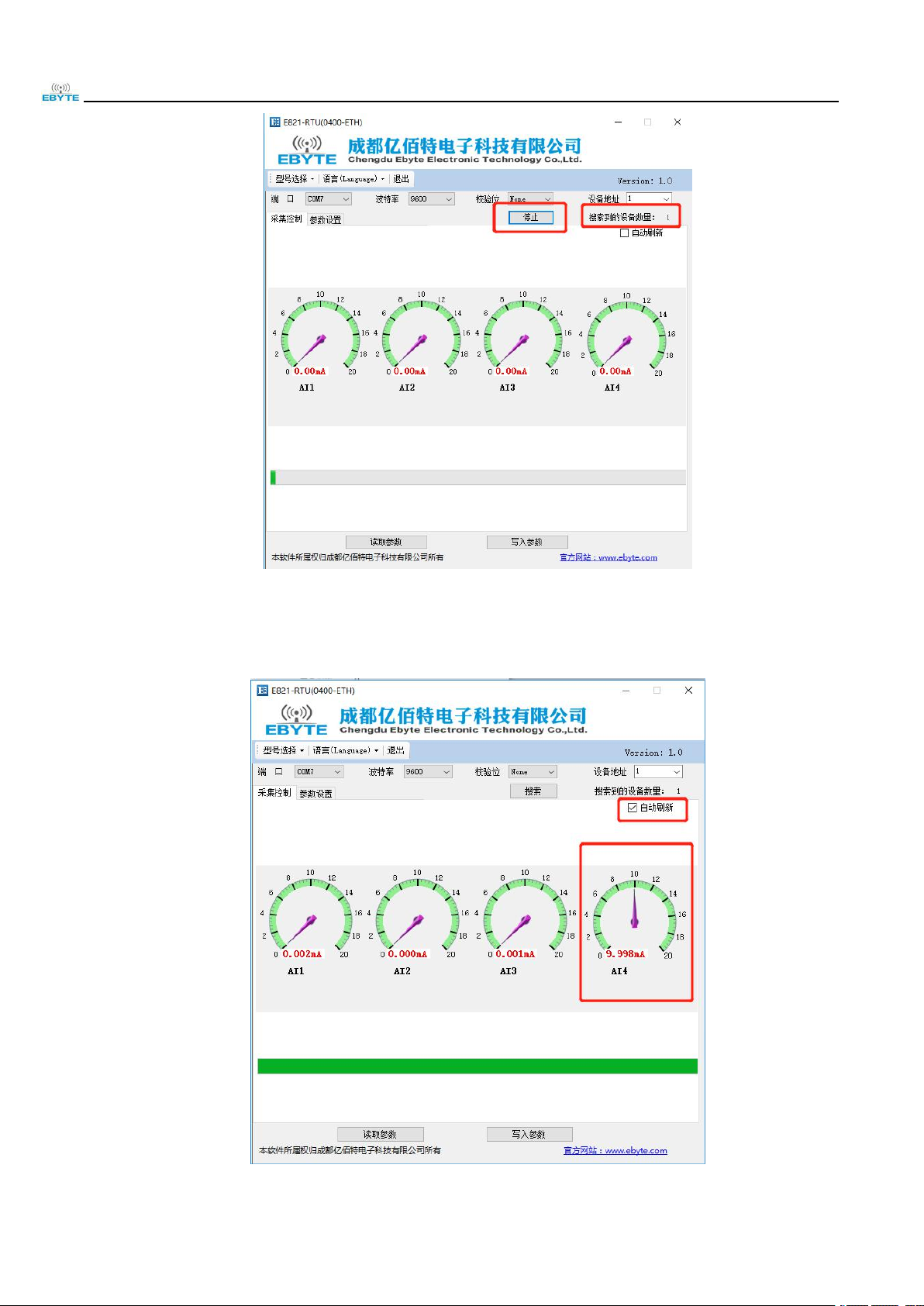
After searching for the actual connected device, click “Stop”; the number of connected devices in the example is 1.
Copyright ©2012–2019, Chengdu Ebyte Electronic Technology Co.,Ltd
Page 7
Chengdu Ebyte Electronic Technology Co.,Ltd E821-RTU (0400-ETH)User Manual
66
At this time, you can see the address of the current device, check "Auto Refresh" to perform analog input reading.
The example shows that channel 4 has 10mA current input.
Copyright ©2012–2019, Chengdu Ebyte Electronic Technology Co.,Ltd
Page 8
Chengdu Ebyte Electronic Technology Co.,Ltd E821-RTU (0400-ETH)User Manual
77
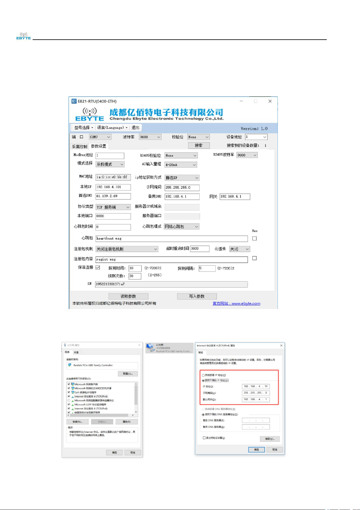
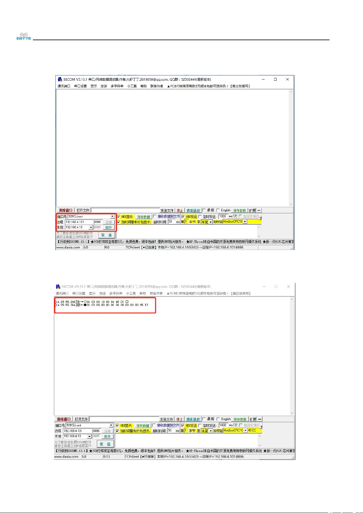
1.2.2 Ethernet control
Click the parameter setting and parameter reading, we can see that the device address is "1", in "slave mode", the
local IP is "192.168.4.101", the subnet mask is "255.255.255.0", the role is "TCP server", and the port number is 8666.
Click Local connection, set the computer IP: "192.168.4.10", subnet mask: "255.255.255.0", gateway: 192.168.4.1.
Copyright ©2012–2019, Chengdu Ebyte Electronic Technology Co.,Ltd
Page 9
Chengdu Ebyte Electronic Technology Co.,Ltd E821-RTU (0400-ETH)User Manual
88
Open the network debugging assistant, set the port number and other parameters, click the connection, you can find
that the device LINK light is on to indicate the connection is successful.
Send Modbus command: 01 03 00 10 00 04 45 CC, to read the current value collected by 4 analog channels.
Copyright ©2012–2019, Chengdu Ebyte Electronic Technology Co.,Ltd
Page 10

Chengdu Ebyte Electronic Technology Co.,Ltd E821-RTU (0400-ETH)User Manual
99
Item
Description
Network parameters
Ethernet Specification
RJ45, 10/100Mbps
Network Protocol
IP, TCP/UDP, ARP, ICMP, IPV4
IP acquisition method
Static IP, DHCP
DNS
Available
Hardware parameters
Size (H*W*D)
108*75*37mm
Weight
230.8±5g
Working temperature
-20℃~+70℃
Storage temperature
-40℃~+85℃
Working humidity
5%~95%
Storage humidity
1%~95%
Working voltage
8V~28V, 8V/143mA, 12V/98mA, 24V/52mA,
28V/45mA
Current acquisition range
0mA~20mA or 4mA-20mA
Accuracy
0.2%
Data interface
RS485: 1200~115200bps, RJ45: 100M
Software parameters
Network type
Ethernet
Configuration command
Modbus TCP/RTU
Network Protocol
Modbus TCP/RTU
Working mode
Master mode, Slave mode
Data transmission mode
TCP/UDP
2. Product description
E821-RTU (0400-ETH) is a data acquisition product which supports four analog (current) inputs and supports
Modbus TCP/RTU protocol. The product is highly easy to use and can be easily and quickly integrated into your system
for remote network-based data acquisition.
2.1 Basic parameters
Copyright ©2012–2019, Chengdu Ebyte Electronic Technology Co.,Ltd
Page 11

Chengdu Ebyte Electronic Technology Co.,Ltd E821-RTU (0400-ETH)User Manual
1010
2.2 Size and Interface description
Copyright ©2012–2019, Chengdu Ebyte Electronic Technology Co.,Ltd
Page 12

Chengdu Ebyte Electronic Technology Co.,Ltd E821-RTU (0400-ETH)User Manual
1111
No
Item
Function
Description
1
RJ45
Ethernet
tandard RJ45 interface, connected to device or PC
2
DC-IN
DC JACK 5.5*2.1mm
Power input, DC 8V~28V, 12V/24V recommended
3
DC-IN +
Crimping terminal
power input positive
Power input, DC 8V~28V, 12V/24V recommended
4
DC-IN -
Crimping terminal
power input negative
Power Ground
5
RS485 G
RS485 ground
Signal ground, can not be connected
6
RS485 A
RS485 A
RS485 B is connected to device A
7
RS485 B
RS485 B
RS485 B is connected to device B
8
Grounding screw
Connecting to ground
Connecting to ground
9
Reset
Reset button
Long Press for 5S effective
10
AI1+
Analog signal input
channel 1 positive
Analog signal input channel, used in combination
with the negative to collect analog data
11
AI1-
Analog signal input
channel 1 negative
Analog signal input channel, used in combination
with the positive to collect analog data
12
AI2+
Analog signal input
channel 2 positive
Analog signal input channel, used in combination
with the negative to collect analog data
13
AI2-
Analog signal input
channel 2 negative
Analog signal input channel, used in combination
with the positive to collect analog data
14
AI3+
Analog signal input
channel 3 positive
Analog signal input channel, used in combination
with the negative to collect analog data
15
AI3-
Analog signal input
channel 3 negative
Analog signal input channel, used in combination
with the positive to collect analog data
16
AI4+
Analog signal input
channel 4 positive
Analog signal input channel, used in combination
with the negative to collect analog data
Copyright ©2012–2019, Chengdu Ebyte Electronic Technology Co.,Ltd
Page 13

Chengdu Ebyte Electronic Technology Co.,Ltd E821-RTU (0400-ETH)User Manual
1212
17
AI4-
Analog signal input
channel 4 negative
Analog signal input channel, used in combination
with the positive to collect analog data
LED Indicator light
1
PWR
Power supply indication
Red after power on, long bright
2
NET
Ethernet connection
indication
Blue and green two-color LED, the blue LED is long
bright after the Ethernet port TCP/UDP connection is
successful. After power-on, the green LED is lit,
indicating that it is initializing.
3
DATA/RST
Data indication/reset
indication
Blue and green two-color LED, blue LED flashes
when data is transmitted and received, green LED
flashes 3 times after reset
Note: It is recommended to connect the case to the ground..
2.3 Reset button description
Long press for 5S is valid. After the reset is successful, the RST LED flashes 3 times, the Modbus device address,
RS485 serial port baud rate and parity bit are restored to the factory settings, other configuration parameters are
unchanged.
Copyright ©2012–2019, Chengdu Ebyte Electronic Technology Co.,Ltd
Page 14

Chengdu Ebyte Electronic Technology Co.,Ltd E821-RTU (0400-ETH)User Manual
13
Register Address Table (Function table: 0x03H, 0x04H, 0x06H, 0x10H)
Register
Address
Number
of
registers
Register properties
Register
type
Register
value range
Default value
Function
Code
30017 (0x0010)
1
AI4 Input value/uA
Read only
0-20000
-
0x03
0x04
30018 (0x0011)
1
AI3 Input value/uA
Read only
-
30019 (0x0012)
1
AI2 Input value/uA
Read only
-
30020 (0x0013)
1
AI1 Input value/uA
Read only
-
Reserve
40078
(0x004D)
1
Device address
Read/Write
1 - 247
01
0x03
0x06
40079
(0x004E)
1
Baud rate
Read/Write
0 - 7
03
40080 (0x004F)
1
Parity bit
Read/Write
0 - 2
00
40081(0x0050)
1
Master mode or
slave mode
Read/Write
0 - 1
01
Reserve
40084(0x0053)
1
Set Analog range
Read/Write
0 - 1
01
Reserve
40098 (0x0061)
3
Set MAC address
Read--
0x03
0x06
0x10
40104 (0x0067)
1
Ethernet restart
Read/Write--
40108
(0x006B)
7
WAN port IP info
Read/Write
-
Static
192.168.4.101
255.255.255.0
192.168.4.1
40122 (0x0079)
4
Set DNS info
Read/Write
-
61.139.2.69
192.168.4.1
40130 (0x0081)
4
Set Network protocol
parameters
Read/Write
-
TCPS,192.168.
4.10, 8886
40146 (0x0091)
1
Set registration
package mode
Read/Write
0-4
“0” Close the
registration
package
40150 (0x0095)
21
Set registration
package content
Read/Write
-
regist msg
40234
(0x00E9)
21
Set heartbeat
package content
Read/Write
-
heartbeat msg
40318
(0x013D)
1
Set heartbeat
package mode
Read/Write
0-1
“0” Network
heartbeat
package
40322 (0x0141)
1
Set heartbeat time
Read/Write
0、2-65535
0
40330 (0x0149)
1
Set clear cache
Read/Write
0-1
Do not clear
the cache data
of the
SOCKET A1
link
40336 (0x014F)
3
Set keep-alive
parameters
Read/Write
-
Detection time:
10s, Detection
interval: 5s,
Detection
times: 30
3. Modbus
3.1 Register Address Table
Copyright ©2012–2019, Chengdu Ebyte Electronic Technology Co.,Ltd
Page 15

Chengdu Ebyte Electronic Technology Co.,Ltd E821-RTU (0400-ETH)User Manual
1414
40350
(0x015D)
1
Set local port
Read/Write
0-65535
8886
40354 (0x0161)
1
Set cloud
transmission
function
Read/Write
0-1
Close
40356 (0x0163)
1
Set timeout restart
time
Read/Write
60-65535
3600
40358 (0x0165)
4
SN code
Read--
Modbus address table
1 (default)
1
2
2
3
3
…
…
245
245
246
246
247
247
Baud rate code value table
0
1200
1
2400
2
4800
3 (default)
9600
4
19200
5
38400
6
57600
7
115200
Parity bit value table
0 (default)
No parity
1
Even parity
2
Odd parity
3.2 Modbus address table
3.3 RS485 serial port baud rate code value table
3.4 RS485 serial port parity bit value table
Copyright ©2012–2019, Chengdu Ebyte Electronic Technology Co.,Ltd
Page 16

Chengdu Ebyte Electronic Technology Co.,Ltd E821-RTU (0400-ETH)User Manual
1515
3.5 Configure parameters by setting software
Select the “Parameter Setting” column to read parameters and write parameters. For specific functions, please refer
to the product function description below.
Copyright ©2012–2019, Chengdu Ebyte Electronic Technology Co.,Ltd
Page 17

Chengdu Ebyte Electronic Technology Co.,Ltd E821-RTU (0400-ETH)User Manual
16
4. Product Function
4.1 Working mode
The working mode has master mode and slave mode, which are configured by Modbus register 40081 (0x0050).
When the register value is 0, it is the master mode; when the register value is 1, it is the slave mode, and default is the
slave mode.
4.1.1 Slave mode
In slave mode (register value is 0x01), the data sent to the device by network or 485 bus (sender) conforms to
Modbus RTU or Modbus TCP protocols, and the address in the data is the device address. The device will respond to the
sender with the same protocol. If the data sent to the device by the network end or 485 bus end does not conform to the
Modbus RTU or Modbus TCP protocol, or meets the Modbus RTU or Modbus TCP protocol, but the data address is
different from that of the device, the data will be discarded.
In the slave mode, the device can directly connect to the device in master mode through the 485 bus. When the slave
is not connected to the network, the network can also access the data of the slave through the master.
4.1.2 Master mode
In slave mode (register value is 0x00), the data sent to the device by network or 485 bus (sender) conforms to
Modbus RTU or Modbus TCP protocols, and the address in the data is the device address. The device will respond to the
sender with the same protocol. If the data sent to the device by the network end or 485 bus end does not conform to the
Modbus RTU or Modbus TCP protocol, or meets the Modbus RTU or Modbus TCP protocol, but the data address is
different from that of the device, the data of 485 bus will be transmitted to the network, and the data on the network will
be transmitted to 485 bus.
This function of host mode can realize the cascade function of devices and the data transmission between 485 bus
and network.
Copyright ©2012–2019, Chengdu Ebyte Electronic Technology Co.,Ltd
Page 18

Chengdu Ebyte Electronic Technology Co.,Ltd E821-RTU (0400-ETH)User Manual
1717
Send
010300 13
00 01
75 CF
Device ModBus
address
Function
code
Analog-data start
address
Read the number of
addresses
CRC check code
Receive
010302
26 DA
23 BF
Device ModBus
address
Function
code
Number of bytes
returned
Analog-data input
value
CRC check code
Send
00 01
00 00
00 060103
00 13
00 01
Transmiss
ion
identifier
Protocol
identifier
Length
Unit
identifier
Functio
n code
Analog-data start
address
Read the number
of addresses
Receive
00 01
00 00
00 0501030226 DA
Transmiss
ion
identifier
Protocol
identifier
Length
Unit
identifier
Functio
n code
Number of bytes
returned
Analog-data input
value
4.2 RTU basic function
4.2.1 Read analog-data AI input
Function code: 03, Read hold-register; 04, Read input-register
Address range: 30017(0x0010)~30020(0x0013)
Remark: The unit of analog input value is uA
E.g.:
Function code 0x03, read AI1 input, assuming AI1 input is 9946uA, the corresponding value should be 0x26 DA
Modbus RTU protocol read analog-data input:
Modbus TCP protocol read analog-data input:
Copyright ©2012–2019, Chengdu Ebyte Electronic Technology Co.,Ltd
Page 19

Chengdu Ebyte Electronic Technology Co.,Ltd E821-RTU (0400-ETH)User Manual
1818
Send
010400 13
00 01
C0 0F
Device ModBus
address
Function
code
Analog-data start
address
Read the number of
addresses
CRC check code
Receive
010402
26 DA
22 CB
Device ModBus
address
Function
code
Number of bytes
returned
Analog-data input
value
CRC check code
Send
00 01
00 00
00 060104
00 13
00 01
Transmiss
ion
identifier
Protocol
identifier
Length
Unit
identifier
Functio
n code
Analog-data start
address
Read the number
of addresses
Receive
00 01
00 00
00 0501040226 DA
Transmiss
ion
identifier
Protocol
identifier
Length
Unit
identifier
Functio
n code
Number of bytes
returned
Analog-data input
value
Send
010300 61
00 03
54 15
Device ModBus
address
Function
code
Start address
Read number of
registers
CRC check code
Receive
01
03061A 00 1C C0 BB FF
16 53
Device ModBus
address
Function
code
Number of
bytes
Read value
CRC check code
Send
00 01
00 00
00 060103
00 61
00 03
Transmissio
Protocol
Length
Unit
Functio
Address
Write value
Function code 0x04, read AI1 input, assuming AI1 input is 9946uA, the corresponding value should be 0x26 DA
Modbus RTU protocol read analog-data input:
Modbus TCP protocol read analog-data input:
4.2.2 Analog AI acquisition range setting
When the value of register 0x40084 (0x0053) is 0, the analog input range is 0 - 20mA;
When the value of register 0x40084 (0x0053) is 1, the analog input range is 4 - 20mA;
Note: When the range is 4-20mA, the input current is <4mA, the register value will be 0.
4.3 Network related functions
4.3.1 Device MAC address reading
Modbus RTU protocol write register:
Copyright ©2012–2019, Chengdu Ebyte Electronic Technology Co.,Ltd
Modbus TCP protocol write register:
Page 20

Chengdu Ebyte Electronic Technology Co.,Ltd E821-RTU (0400-ETH)User Manual
1919
n identifier
identifier
identifier
n code
Receive
00 01
00 00
00 09
010306
1A 00 1C C0 BB
FF
Transmissio
n identifier
Protocol
identifier
Length
Unit
identifier
Functio
n code
Number of bytes
Read value
Send
010301 65
00 04
55 EA
Device ModBus
address
Function
code
Start address
Read number of
registers
CRC check code
Receive
01
030819 05 21 14 00 13 55 50
F9 AA
Device ModBus
address
Function
code
Number of
bytes
Read value
CRC check code
Send
00 01
00 00
00 060103
01 65
00 04
Transmissio
n identifier
Protocol
identifier
Length
Unit
identifier
Functio
n code
Address
Read number
Receive
00 01
00 00
00 0B
010308
19 05 21 14 00 13 55 50
Transmissio
n identifier
Protocol
identifier
Length
Unit
identifier
Functio
n code
Number
of bytes
Read value
Send
010600 67
00 01
F9 D5
Device ModBus
address
Function
code
Address
Write value
CRC check code
Receive
010600 67
00 01
F9 D5
Device ModBus
address
Function
code
Address
Write value
CRC check code
Send
00 01
00 00
00 060106
00 67
00 01
Transmission
identifier
Protocol
identifier
Length
Unit
identifier
Functio
n code
Address
Write value
Note: 1A 00 1C C0 BB FF is the MAC address of the device, the device has a unique MAC address.
4.3.2 Device SN code reading
Modbus RTU protocol read register:
Modbus TCP protocol read register:
Note: 19 05 21 14 00 13 55 50 is the device SN code, the devices have different SN codes.
4.3.3 Network function parameter validation command (Ethernet restart command)
Modbus RTU protocol write register:
Copyright ©2012–2019, Chengdu Ebyte Electronic Technology Co.,Ltd
Modbus TCP protocol write register:
Page 21

Chengdu Ebyte Electronic Technology Co.,Ltd E821-RTU (0400-ETH)User Manual
2020
Receive
00 01
00 00
00 06
010600 67
00 01
Transmission
identifier
Protocol
identifier
Length
Unit
identifier
Functio
n code
Address
Transmission
identifier
Send
01
10
00 6B
00 07
0E
00 00 C0 A8 04 65 FF FF FF 00 C0 A8 04
01
BE 17
Device
ModBus
address
Function
code
Address
Register
Length
Number
of bytes
Write value
CRC
check
code
Receive
01
10
00 6B
00 07
F0 17
Device ModBus
address
Function
code
Address
Register Length
CRC check code
Se
nd
00 01
00 00
00 150110
00 6B
00 07
0E
00 00 C0 A8 04 65 FF
FF FF 00 C0 A8 04 01
Transmis
sion
identifier
Protocol
identifier
Length
Unit
identifier
Function
code
Address
Register
Length
Number
of bytes
Write value
Recei
ve
00 01
00 00
00 150110
00 6B
00 07
Transmission
identifier
Protocol
identifier
Length
Unit
identifier
Function
code
Address
Register
length
Send0110
00 79
00 04
08
3D 8B 02 45
C0 A8 04 02
E0 50
Special note: You can restart the Ethernet component by writing the value 0X00 01 to the address 0X00 67. After
the Ethernet parameters have been configured, you have to execute the restart command. Otherwise, the configured
parameters will not take effect.
4.3.4 WAN port IP info configuration
Modbus RTU protocol write WAN port IP register:
Modbus TCP protocol write register:
Note: 00 00 is static mode, 00 01 is dynamic mode, C0 A8 04 65 ( 192.168.4.101 ) is IP address. FF FF FF 00
(255.255.255.0) is subnet mask. C0 A8 04 01(192.168.4.1) is gateway addres. When set to dynamic mode, the IP
address, subnet mask, and gateway address are required for the format. The IP address of the device needs to be obtained
through the query command.
4.3.5 Set DNS
Modbus RTU protocol write DNS register:
Copyright ©2012–2019, Chengdu Ebyte Electronic Technology Co.,Ltd
Page 22

Chengdu Ebyte Electronic Technology Co.,Ltd E821-RTU (0400-ETH)User Manual
2121
Device ModBus
address
Function
code
Address
Register
length
Number
of bytes
Write value
CRC check
code
Receive
011000 79
00 04
10 13
Device ModBus
address
Function
code
Address
Register length
CRC check code
Send
00 01
00 00
00 0F0110
00 79
00 04
08
3D 8B 02 45
C0 A8 04 02
Transmission
identifier
Protocol
identifier
Length
Unit
identifier
Function
code
Address
Register
length
Number
of bytes
Write value
Receive
00 01
00 00
00 0F
01
10
00 79
00 04
Transmission
identifier
Protocol
identifier
Length
Unit identifier
Function
code
Address
Register
length
Send
01
10
00 81
00 04
08
00 00 C0 A8 04 0A 22
B6
81 3B
Device ModBus
address
Function
code
Address
Register
length
Number
of bytes
Write value
CRC check
code
Receive
011000 81
00 04
91 E2
Device ModBus
address
Function
code
Address
Register length
CRC check code
Send
00 01
00 00
00 0F0110
00 81
00 04
08
00 00 C0 A8
04 0A 22 B6
Transmission
identifier
Protocol
identifier
Length
Unit
identifier
Function
code
Address
Register
length
Number
of bytes
Write value
Receive
00 01
00 00
00 0F0110
00 81
00 04
Transmission
identifier
Protocol
identifier
Length
Unit identifier
Function
code
Address
Register
length
Modbus TCP protocol write register:
Note: 3D 8B 02 45 is preferred DNS server address, C0 A8 04 02 is Alternate DNS server address.
4.3.6 Set network protocol parameters
Modbus RTU protocol write DNS register:
Modbus TCP protocol write register:
Copyright ©2012–2019, Chengdu Ebyte Electronic Technology Co.,Ltd
Page 23

Chengdu Ebyte Electronic Technology Co.,Ltd E821-RTU (0400-ETH)User Manual
2222
Send
010600 91
00 00
D8 27
Device ModBus
address
Function
code
Address
Write value
CRC check code
Receive
010600 91
00 00
D8 27
Device ModBus
address
Function
code
Address
Write value
CRC check code
Send
00 01
00 00
00 060106
00 91
00 00
Transmission
identifier
Protocol
identifier
Length
Unit
identifier
Function
code
Address
Write value
Receive
00 01
00 00
00 060106
00 91
00 00
Transmission
identifier
Protocol
identifier
Length
Unit
identifier
Function
code
Address
Write value
Send
01
10
00 95
00 15
2A
00 28 41 42 43 68 23 67 AA 00
2A 00 30 00 00 00 00 00 00 00 00
00 00 00 00 11 00 22 00 33 00 44 00
12 33 23 11 10 1D 1C BB AA
1C 91
Device
ModBus
address
Function
code
Address
Register
length
Number
of bytes
Write value
CRC
check
code
Receive
011000 95
00 15
11 EA
Device ModBus
address
Function
code
Address
Register length
CRC check code
Note: 00 00 isTCP serve, 00 01 is TCP client, 00 02 is UDP server, 00 03 is UDP client. C0 A8 04 0A is the IP
address or domain name of the target server when it is set to "client", 22 B6 is port number, it is local port number when
in server mode, it is remote port number when in client mode.
4.3.7 Set the registration package mode
Modbus RTU protocol write register:
Modbus TCP protocol write register:
Note: 00 00 means disable the registration package mechanism, 00 01 means that only one user-defined registration
package is sent when the first link to the server, 00 02 means that only a registration packet of 6-byte MAC is sent when
the first link to the server, 00 03 means adding custom packet data before each packet sent to the server. 00 04 means
adding 6 bytes of MAC as registration packet data before each packet sent to the server.
4.3.8 Set the registration package contents
Modbus RTU protocol write register:
Copyright ©2012–2019, Chengdu Ebyte Electronic Technology Co.,Ltd
Page 24

Chengdu Ebyte Electronic Technology Co.,Ltd E821-RTU (0400-ETH)User Manual
2323
S
e
n
d
00 01
00 00
00 310110
00 95
00 15
2A
00 28 41 42 43 68 23
67 AA 00 2A 00 30 00
00 00 00 00 00 00 00
00 00 00 00 11 00 22
00 33 00 44 00 12 33
23 11 10 1D 1C BB AA
Transmiss
ion
identifier
Protocol
identifier
Length
Unit
identifier
Function
code
Address
Register
length
Number
of bytes
Write value
Receive
00 01
00 00
00 310110
00 95
00 15
Transmission
identifier
Protocol
identifier
Length
Unit
identifier
Function
code
Address
Register
length
Send
010601 3D
00 00
19 FA
Device ModBus
address
Function
code
Address
Write value
CRC check code
Receive
010601 3D
00 00
19 FA
Device ModBus
address
Function
code
Address
Write value
CRC check code
Send
00 01
00 00
00 060106
01 3D
00 00
Transmission
identifier
Protocol
identifier
Length
Unit
identifier
Function
code
Address
Write value
Receive
00 01
00 00
00 060106
01 3D
00 00
Transmission
identifier
Protocol
identifier
Length
Unit
identifier
Functio
n code
Address
Write value
Modbus TCP protocol write register:
Note: 00 indicatess HEX, 01 indicates ASCII. 28 indicates the content length of the registration package. 41 42 43
68 23 67 AA 00 2A 00 30 00 00 00 00 00 00 00 00 00 00 00 00 11 00 22 00 33 00 44 00 12 33 23 11 10 1D 1C BB AA
indicates the contents of the registration package. For example: send the registration package content: ebyte, the write
value is 01 05 65 62 79 74 65 00 00 00 00 00 00 00 00 00 00 00 00 00 00 00 00 00 00 00 00 00 00 00 00 00 00 00 00 00
00 00 00 00 00 00.
4.3.9 Set heartbeat package mode
Modbus RTU protocol write register:
Modbus TCP protocol write register:
Copyright ©2012–2019, Chengdu Ebyte Electronic Technology Co.,Ltd
Page 25

Chengdu Ebyte Electronic Technology Co.,Ltd E821-RTU (0400-ETH)User Manual
2424
Receive
01
10
00 E9
00 15
D0 32
Device ModBus
address
Function
code
Address
Register length
CRC check code
Se
nd
00 01
00 00
00 310110
00 E9
00 15
2A
00 28 41 42 43 68 23
67 AA 00 2A 00 30 00
00 00 00 00 00 00 00
00 00 00 00 11 00 22
00 33 00 44 00 12 33
23 11 10 1D 1C 1B 1A
Transm
ission
identifi
er
Protocol
identifier
Length
Unit
identifier
Function
code
Address
Register
length
Number
of bytes
Write value
Recei
ve
00 01
00 00
00 31
01
10
00 E9
00 15
Transmission
identifier
Protocol
identifier
Length
Unit identifier
Function
code
Address
Register
length
Send
010601 41
01 AA
59 CD
Device ModBus
Function
Address
Write value
CRC check code
Send
01
10
00 E9
00 15
2A
00 28 41 42 43 68 23 67 AA 00
2A 00 30 00 00 00 00 00 00 00 00
00 00 00 00 11 00 22 00 33 00 44
00 12 33 23 11 10 1D 1C 1B 1A
9D 8C
Device
ModBus
address
Function
code
Address
Register
length
Number
of bytes
Write value
CRC
check
code
Note: 00 00 is network heartbeat package, 00 01 is serial port heartbeat package.
4.3.10 Set heartbeat package content
Modbus RTU protocol write register:
Modbus TCP protocol write register:
Note: 00 is HEX, 01 is ASCII. 28 is the content length of the heartbeat packet. 41 42 43 68 23 67 AA 00 2A 00 30
00 00 00 00 00 00 00 00 00 00 00 00 11 00 22 00 33 00 44 00 12 33 23 11 10 1D 1C 1B 1A is heartbeat package content.
For example: send the heartbeat package content: ebyte, the write value is 01 05 65 62 79 74 65 00 00 00 00 00 00 00 00
00 00 00 00 00 00 00 00 00 00 00 00 00 00 00 00 00 00 00 00 00 00 00 00 00 00 00
4.3.11 Set heartbeat package time
Modbus RTU protocol write register:
Copyright ©2012–2019, Chengdu Ebyte Electronic Technology Co.,Ltd
Page 26

Chengdu Ebyte Electronic Technology Co.,Ltd E821-RTU (0400-ETH)User Manual
2525
address
code
Receive
010601 41
01 AA
59 CD
Device ModBus
address
Function
code
Address
Write value
CRC check code
Send
00 01
00 00
00 060106
01 41
01 AA
Transmission
identifier
Protocol
identifier
Length
Unit
identifier
Function
code
Address
Write value
Receive
00 01
00 00
00 060106
01 41
01 AA
Transmission
identifier
Protocol
identifier
Length
Unit
identifier
Function
code
Address
Write value
Send
010601 49
00 00
59 E0
Device ModBus
address
Function
code
Address
Write value
CRC check code
Receive
010601 49
00 00
59 E0
Device ModBus
address
Function
code
Address
Write value
CRC check code
Send
00 01
00 00
00 060106
01 49
00 00
Transmission
identifier
Protocol
identifier
Length
Unit
identifier
Function
code
Address
Write value
Receive
00 01
00 00
00 060106
01 49
00 00
Transmission
identifier
Protocol
identifier
Length
Unit
identifier
Function
code
Address
Write value
Send0110
01 4F
00 03
06
02 D1 02 D1 00
31
BD 3D
Modbus TCP protocol write register:
Note: 00 00 is the heartbeat packet time. 00 00 means to turn off the heartbeat packet, the value cannot be 1, and the
range is 2-65535.
4.3.12 Clear the cache
Modbus RTU protocol write register:
Modbus TCP protocol write register:
Note: 00 00 indicates that the cached data of the SOCKET A1 link is not cleared. 00 01 indicates that the cached
data of the SOCKET A1 link is cleared, but the serial cache data is not cleared.
4.3.13 Set keep-alive parameters
Modbus RTU protocol write register:
Copyright ©2012–2019, Chengdu Ebyte Electronic Technology Co.,Ltd
Page 27

Chengdu Ebyte Electronic Technology Co.,Ltd E821-RTU (0400-ETH)User Manual
2626
Device ModBus
address
Function
code
Address
Register
length
Number
of bytes
Write value
CRC check
code
Receive
01
10
01 4F
00 03
B0 23
Device ModBus
address
Function
code
Address
Register length
CRC check code
Send
00 01
00 00
00 0D0110
01 4F
00 03
06
02 D1 02
D1 00 31
Transmission
identifier
Protocol
identifier
Length
Unit
identifier
Function
code
Address
Register
length
Number
of bytes
Write
value
Receive
00 01
00 00
00 0D0110
01 4F
00 03
Transmission
identifier
Protocol
identifier
Length
Unit
identifier
Function
code
Address
Register length
Send
010601 5D
11 A1
D4 0C
Device ModBus
address
Function
code
Address
Write value
CRC check code
Receive
010601 5D
11 A1
D4 0C
Device ModBus
address
Function
code
Address
Write value
CRC check code
Send
00 01
00 00
00 060106
01 5D
11 A1
Transmission
identifier
Protocol
identifier
Length
Unit
identifier
Function
code
Address
Write value
Receive
00 01
00 00
00 060106
01 5D
11 A1
Transmission
identifier
Protocol
identifier
Length
Unit
identifier
Function
code
Address
Write value
Modbus TCP protocol write register:
Note: 02 D1 indicates that if there is no data message transmission after the TCP link, the detection message will be
started. 00 00 indicates that the keep-alive function is turned off, with a value of 2-7200 seconds. 02 D1 time interval
between the previous detection message and the next detection message is a value of 2-7200 seconds. 00 31 is the
maximum number of detection failures. When the number of sniffing failures reaches this number, the TCP connection
will be disconnected, with a value of 2-255 times.
4.3.14 Set local port number
Modbus RTU protocol write register:
Modbus TCP protocol write register:
Copyright ©2012–2019, Chengdu Ebyte Electronic Technology Co.,Ltd
Page 28

Chengdu Ebyte Electronic Technology Co.,Ltd E821-RTU (0400-ETH)User Manual
2727
Send
010601 61
00 01
18 28
Device ModBus
address
Function
code
Address
Write value
CRC check code
Receive
010601 61
00 01
18 28
Device ModBus
address
Function
code
Address
Write value
CRC check code
Send
00 01
00 00
00 060106
01 61
00 01
Transmission
identifier
Protocol
identifier
Length
Unit
identifier
Function
code
Address
Write value
Receive
00 01
00 00
00 060106
01 61
00 01
Transmission
identifier
Protocol
identifier
Length
Unit
identifier
Function
code
Address
Write value
Send
010601 63
FF A0
39 A0
Device ModBus
address
Function
code
Address
Write value
CRC check code
Receive
010601 63
FF A0
39 A0
Device ModBus
address
Function
code
Address
Write value
CRC check code
Send
00 01
00 00
00 060106
01 63
FF A0
Transmissio
n identifier
Protocol
identifier
Length
Unit
identifier
Functio
n code
Address
Write value
Receive
00 01
00 00
00 06
010601 63
FF A0
Transmissi
on
Protocol
identifier
Length
Unit
identifier
Functio
n code
Address
Write value
Note: 11 A1 indicates the A1 local port, 00 00 indicates a random port with a value of 1-65535.
4.3.15 Set cloud transparent transmission function
Modbus RTU protocol write register:
Modbus TCP protocol write register:
Note: 00 00 mens cloud transmission function is off, 00 01 means on.
4.3.16 Set timeout restart time
Modbus RTU protocol write register:
Modbus TCP protocol write register:
Copyright ©2012–2019, Chengdu Ebyte Electronic Technology Co.,Ltd
Page 29

Chengdu Ebyte Electronic Technology Co.,Ltd E821-RTU (0400-ETH)User Manual
2828
identifier
Version
Edit date
Description
Issued by
1.0
-
Initial version
-
1.1
2019/8/15
Format revision
lyl
Note: FF A0 indicates the restart time, the value is 60-65535. This feature is used to reset the Ethernet if the
Ethernet has not received any data for a long time.
Important Statement
All rights to interpret and modify this manual belong to Ebyte.
This manual will be updated based on the upgrade of firmware and hardware, please refer to the latest version.
Please refer to our website for new product information.
Reversion History
About Us
Technical support: support@cdebyte.com;
Documents and RF Setting download link: www.ebyte.com
Tel:+86-28-61399028 Ext. 812
Fax:028-64146160
Web:www.ebyte.com
Address:Innovation Center B333-D347, 4# XI-XIN Road,Chengdu, Sichuan, China
Copyright ©2012–2019, Chengdu Ebyte Electronic Technology Co.,Ltd
 Loading...