

Ebyte E800-DTU, Z2530-485-27 User Manual
ZigBee Ad Hoc Network Wireless Modem
E800-DTU(Z2530-485-27) User Manual
Chengdu Ebyte Electronic Technology Co.,Ltd.

E800-DTU Wireless Data Transmission Modem E800-DTU(Z2530-485-27) User Manual
Copyright ©2012–2017, Chengdu Ebyte Electronic Technology Co.,Ltd 1
1. Introduction
1.1. Product Introduction
The E800-DTU (Z2530-485-27) is a ZigBee-based wireless modem with various functions such as transparent transmission,
protocol transmission, and AT configuration etc. As a communication medium, wireless data transmission modem has certain
scope of application same as fiber, microwave and bright line. It provides real-time, reliable data transmission of monitoring
signals in private networks under special conditions, featuring low cost, convenient installation and maintenance, strong
diffraction ability, flexible networking structure and long coverage, and suitable for the occasions with many points while
scattered and complex geographical environment. It can be connected to data terminals such as PLC, RTU, rain gauge and level
gauge.
1.2. Features
★ All core components are original imported, Compared with the current imported wireless modem, it features the most
advanced, the smallest and has the best price.
★ Different transmit power are available, and all technical indicators meet European industrial standards.
★ With a temperature compensated crystal, the frequency stability is better than ±2ppm.
★ Operating temperature range: -40 to +85 DEG C, adapt to the harsh working environment, the real industrial products.
★ All aluminum alloy casing, compact size, easy installation, good heat dissipation; perfect shielding design, good
electromagnetic compatibility and strong anti-interference ability.
★ Multiple protection functions such as reverse power protection, over-current protection, and antenna surge protection greatly
increase the reliability of the radio.
★ Powerful software features, all parameters, such as power, frequency, address ID, etc., can be programmed.
★ Built-in watchdog, and precise time layout, once an exception occurs, the module will automatically restart, and can continue
to work according to the previous parameter settings.

E800-DTU Wireless Data Transmission Modem E800-DTU(Z2530-485-27) User Manual
Copyright ©2012–2017, Chengdu Ebyte Electronic Technology Co.,Ltd 2
1.3. Characteristics
No.
Characteristics
Description
1
Role switching
The user can use the serial port command to let the device switch between the three types of coordinator,
router and terminal.
2
Automatic networking
Supports power-on automatic networking. The coordinator automatically builds up the network by power,
and the terminals and routers automatically search and join the network.
3
Network self-healing
Lost network automatic reconnection function. The network intermediate node is lost, and other networks
automatically join or maintain the original network. (The isolated node automatically joins the original
network, and the non-isolated node maintains the original network.)
The coordinator is lost and there are non-isolated nodes in the original network. The coordinator can join
the network again or the coordinator of the original PAN_ID set by the same user can join the original
network.
5
Data retention time
setting
In the state of the coordinator and router, the user can set the data storage time and use it in conjunction
with the terminal in the sleep mode to save the data of the terminal device and send the data to the terminal
after the terminal wakes up.
Save up to 3 pieces of data, if it is exceeded, automatically clear the first data! After the data is saved, the
data heap is automatically cleared.
6
Automatic resend
In single broadcast(point transmission) mode, when the device fails to send to the next node, it
automatically retransmits every message three times.
7
Automatic routing
The module supports network routing function. Routers and coordinators carry network data routing
functions, and users can form multi-hop networks.
8
Support encryption
protocol
The module uses AES 128-bit encryption to change network encryption and anti-listening. Users can
change the network key by themselves, and the devices with the same network key can communicate
normally.
9
Support Serial Port
Configuration
Module built-in serial instructions, users can configure (view) the parameters and functions of the module
through the serial instructions.
10
Multi-type data
communication
Supports all-network broadcast, multicast and on-demand (single broadcast) functions. Several
transmission methods are also supported in broadcast and single broadcast modes, please refer to the
details.
11
Multiple working mode
selection
It supports three working modes: transparent transmission mode, semi-through mode, protocol mode, and
user can switch freely.
12
Channel change
Supports 16 channel changes from 11 to 26 (2405~2480MHZ), and different channels correspond to
different frequency bands.
13
Network PAN_ID change
Any switch of the network PAN_ID, the user can customize the PAN_ID to join the corresponding
network or automatically select the PAN_ID to join the network.
14
Serial Port Baud Rate
Change
The user can set the baud rate up to 1M, default digit is 8 bits, stop bit is 1 bit, no parity bit.
15
Short address collection
The user can find the corresponding short address according to the module MAC address (unique, fixed)
that has joined the network.
16
Instruction format
switching
This module supports AT command and HEX command, which are easy to configure.
17
Module reset
The user can reset the module through the serial port command.
18
One-click Recovery Baud
Rate
This module supports one-button recovery of baud rate. This function can be used when the user forgets
the baud rate. The default baud rate is 115200.
19
Restore factory settings
Users can restore the factory settings of the module through serial port commands.
1.4. Serial Products
SN.
Model Number
RF Chip
Frequency
Hz
Air Data Rate
bps
Power
dBm
Interface
Distance
km
Antenna Interface
1
E800-DTU
(Z2530-485-27)
CC2530
2.4G
250K
27
RS485
2.5
SMA-K
2
E800-DTU
(Z2530-485-20)
CC2530
2.4G
250K
20
RS485
1.0
SMA-K
★ The E18 modules can communicate with the above model★

E800-DTU Wireless Data Transmission Modem E800-DTU(Z2530-485-27) User Manual
Copyright ©2012–2017, Chengdu Ebyte Electronic Technology Co.,Ltd 3
2. Installation Size
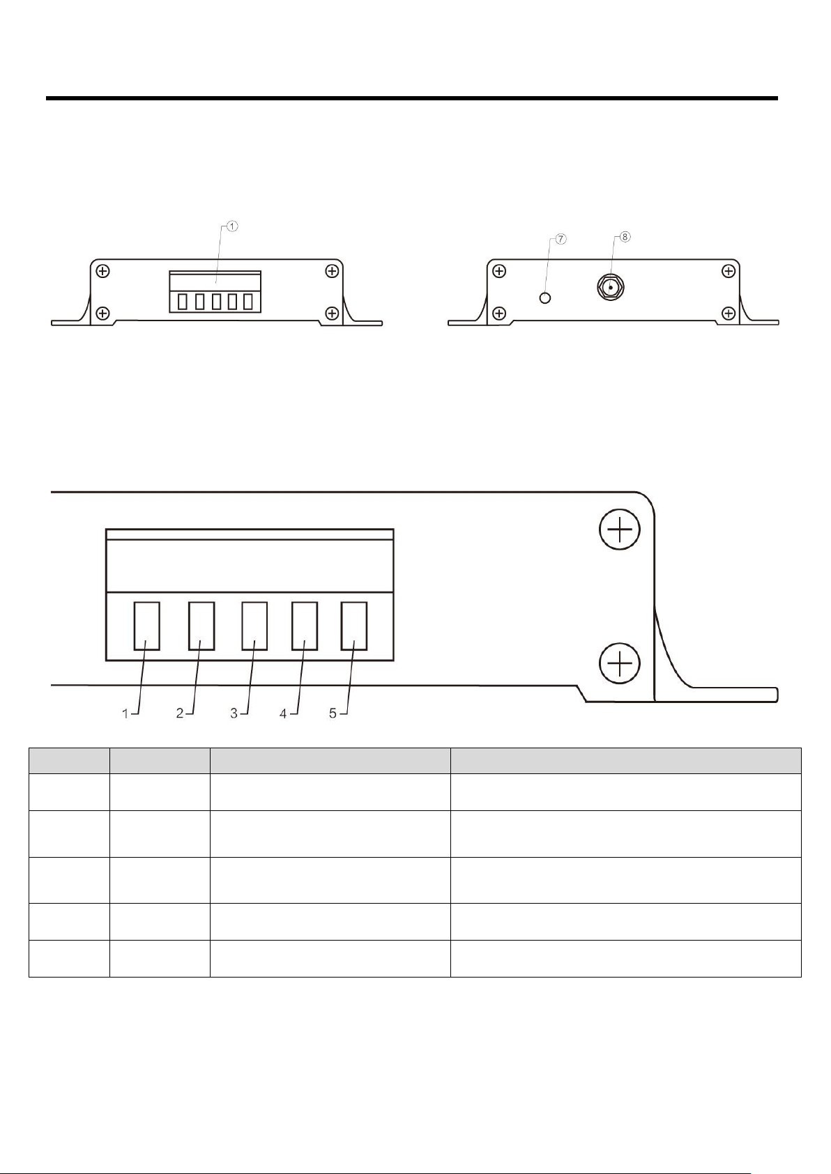
2.1. Department instructions
Pin No.
Name
Function
Description
1
3.81mm Terminals
Communication interface
power interface
Standard RS-485 interface and crimped power interface
2 PWR-LED
Power Indicator
Red, always on when the power is turned on
3 TX-LED
Sending indicator
Yellow, flashing when sending data
4 RX-LED
Receiving indicator
Yellow, flashing when receiving data
5 LINK-LED
Connection indicator
Red, be off when connected to the network, always on when there is no
network.
6 RUN-LED
Running lights
Red, system operation instructions, extinguish means normal operation,
constant light means running error.
7
Baud Rate Reset Switch
Tact Switch
Press and reset the baud rate(115200)
8 Antenna interface
SMA-K interface
External thread, 10mm long, characteristic impedance 50Ω
E800-DTU Wireless Data Transmission Modem E800-DTU(Z2530-485-27) User Manual
Copyright ©2012–2017, Chengdu Ebyte Electronic Technology Co.,Ltd 4
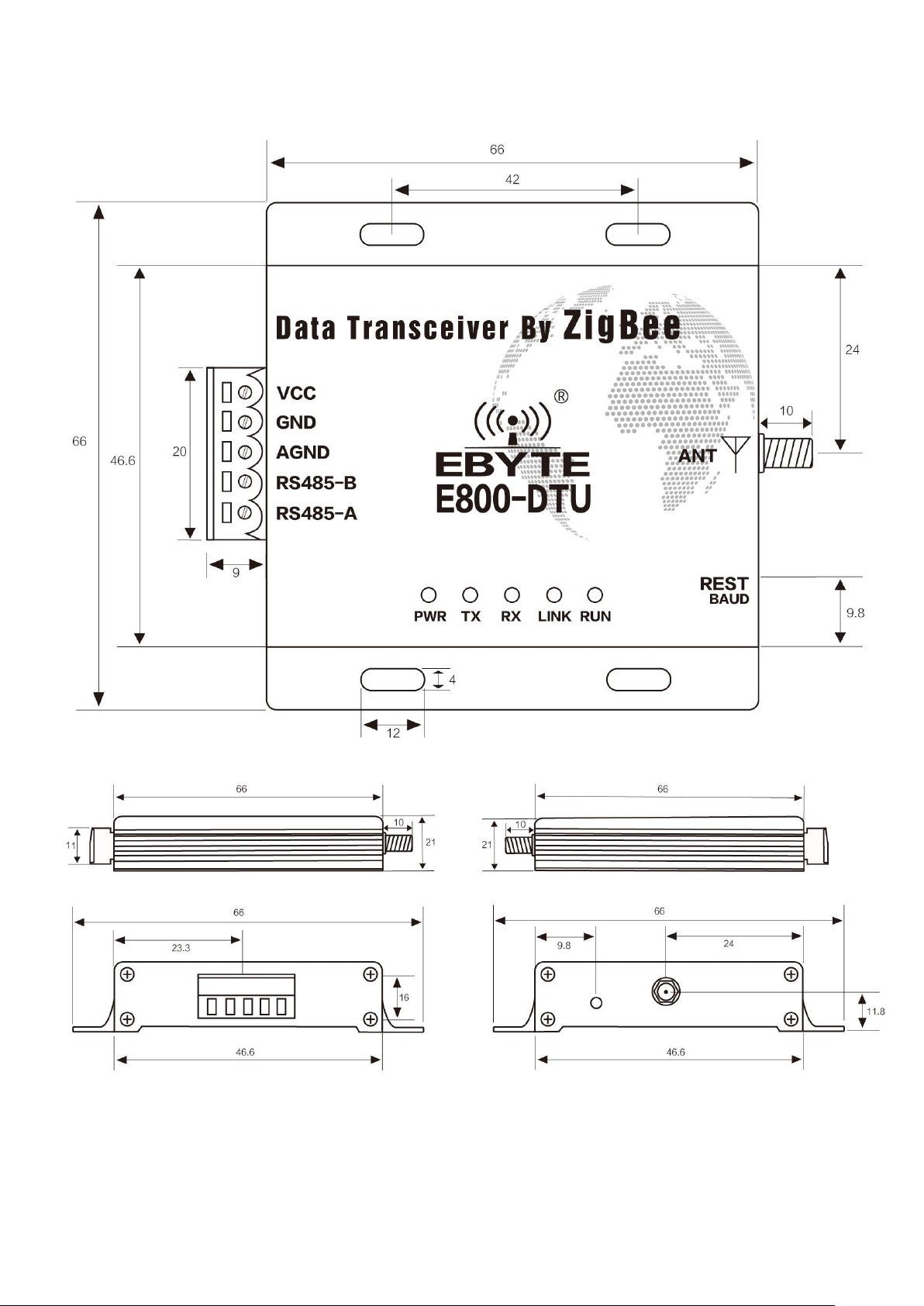
2.2. Product Size
单位:毫米
E800-DTU Wireless Data Transmission Modem E800-DTU(Z2530-485-27) User Manual
Copyright ©2012–2017, Chengdu Ebyte Electronic Technology Co.,Ltd 5
3. Interface Definition
3.1. Power Interface Description
The user needs to use the VCC and GND terminal in ① to supply power. The E800-DTU can be powered by 8~28V DC. It
is recommended to use 12V or 24V DC power supply.
3.2. RS485 Interface Description
The E800-DTU (Z2530-485-27) uses the RS485 communication protocol. How to connect the communication cable, please
select the corresponding interface crimping wire in the ① 3.81mm terminal block. See below for details.
Pin No.
Definition
Function
Description
1
VCC
Crimp power connector, positive
8~28V DC, 12V or 24V is recommended
2
GND
Crimp power connector, positive
The negative pole of the power supply is connected to the
system and the housing.
3
AGND
Common ground interface
It can be connected with the grounding end of external
equipment, or can not be processed.
4
RS485-B
Serial port terminal
Externally connected to the B of other RS485 devices
5
RS485-A
Serial port terminal
Externally connected to the A of other RS485 devices
★ Note: The modem will be poor communication when connecting multiple devices, while connecting a single device is not, please
try to parallel connect 120Ω resistor between 485_A terminal and 485_B terminal.

E800-DTU Wireless Data Transmission Modem E800-DTU(Z2530-485-27) User Manual
Copyright ©2012–2017, Chengdu Ebyte Electronic Technology Co.,Ltd 6
4. Function
4.1. Working Mode
Mode
Node Type
Description
Data communication
display mode
Mode1
(Transparent
transmission mode)
Coordinator
Serial data is transmitted to non-sleeping devices in the network through
broadcasting.
Data carrier formats can be
configured by instructions:
1. Display the mac address
of sender
2. 2Display the short
address of sender
3. Display the RSSI value
of the shortest path of the
message
(Configure display mode
as no display and any one or
more display modes )
Router
The serial port data is transparently transmitted to the coordinator through
on-demand. (Note:The end device cannot receive the transparent data
of mode 1 in sleep mode)
Terminal
Mode 2
(Semi-transparent
mode)
Coordinator
The module transmits in a full protocol according to the fixed format of the
data transmission.On-demand, broadcast, multicast are available.
Please refer to "HEX Data Communication Instructions" for details.
Router
The serial data is transparently transmitted to the coordinator via on-demand.
Terminal
Mode3
(Protocol mode)
Coordinator
The module transmits in a full protocol according to the fixed format of the
data transmission.On-demand, broadcast, multicast are available.
Please refer to "HEX Data Communication Instructions" for details.
N/A
Router
Terminal
Note: Only mode 3 can be selected for GPIO function configuration. Any mode can communicate with each other without affecting each other.
4.2. Introduction to protocol mode communication
No.
Usage
method
Description
1
Broadcast
In the case of joining the network, users can broadcast on the whole network according to the instructions (divided into
three broadcast modes)
1、Broadcast mode 1 ——The message is broadcast to all devices in the network.
2、Broadcast mode 2 ——The message is broadcast to devices that only receive on (except sleep mode).
3、Broadcast mode 3 ——The message is broadcast to all full-featured devices (routers and coordinators).
2
Group
broadcast
In the case of joining the network, users can multicast all the non-dormant devices in the network.
3
point
broadcast
In the case of joining the network, users can communicate with devices on the network in a short address according to the
command (divided into three broadcast modes)
1、Transparent transmission——(No information carried)
2、Short address method——(Short address as the carried information)
3、MAC address method——(MAC address as the carried information)
Note: Please refer to the “HEX Data Communication Instructions” for details.
E800-DTU Wireless Data Transmission Modem E800-DTU(Z2530-485-27) User Manual
Copyright ©2012–2017, Chengdu Ebyte Electronic Technology Co.,Ltd 7
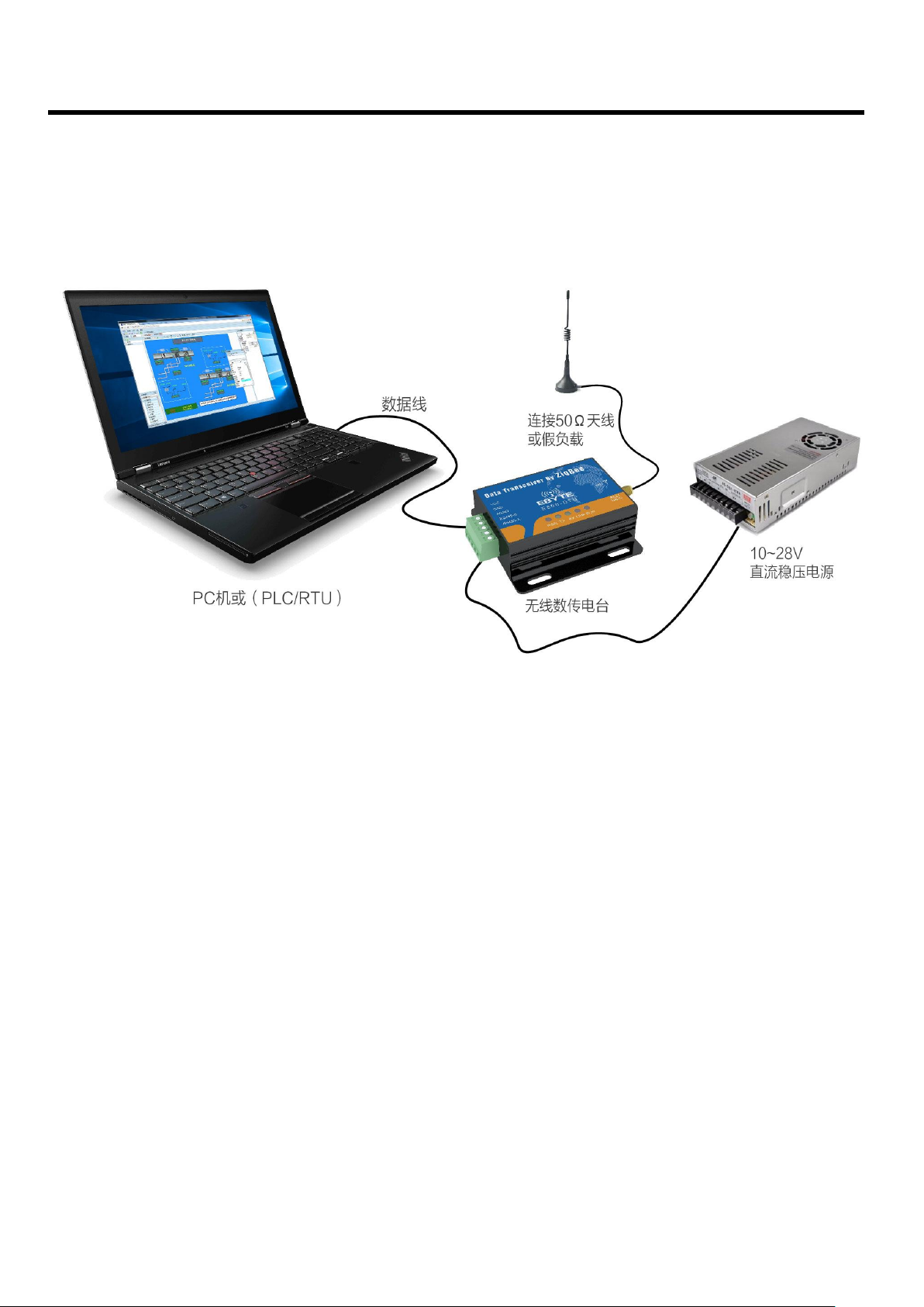
5. Quick Start
5.1. Use Connection Diagram
• ZigBee ad hoc network module is simple and easy to use. In order to let users be familiar with this products quickly, this
section will guide users to configure and communicate in various modes through simple configuration. The default operation
mode is mode 3 (protocol mode).
5.2. Network formation and communication

E800-DTU Wireless Data Transmission Modem E800-DTU(Z2530-485-27) User Manual
Copyright ©2012–2017, Chengdu Ebyte Electronic Technology Co.,Ltd 8
No.
Note
1
【Create network】:
① Connect the Zigbee-DTU through USB to RS485 board.
② Open the PC software "Zigbee_Setting_V1.1", select the port number, set the serial baud rate (default 115200),
and open the serial port.;
③ Click “Read Parameters‘’ to read module parameters
④ Select the node type as the coordinator and write the parameters. Wait for the coordinator to start creating the
network, and the user can view the module parameters.
Configure network parameters:(PAN ID is automatic when it’s FFFFFF)
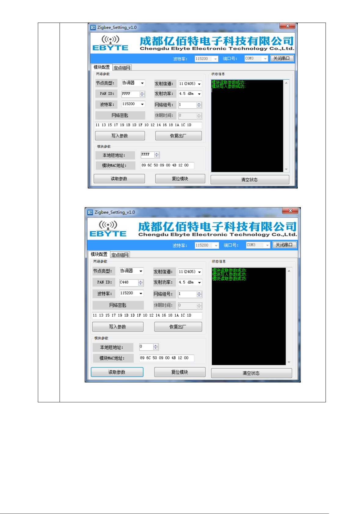
E800-DTU Wireless Data Transmission Modem E800-DTU(Z2530-485-27) User Manual
Copyright ©2012–2017, Chengdu Ebyte Electronic Technology Co.,Ltd 9
Read parameters after the network is built:
⑤ Choose another module and set it as a router or terminal according to the same steps (the module default as a
terminal, users don’t need to configure, our test is a terminal).
 Loading...