

Page 1

E76-433M20S User Manual
EFR32 433MHz SMD Wireless Module
Page 2

Chengdu Ebyte Electronic Technology Co.,Ltd. E76-433M20S User Manual
Copyright ©2012–2018, Chengdu Ebyte Electronic Technology Co.,Ltd.
1
目录
1. Product Overview.................................................................................................................................................................................2
1.1 Brief Introduction......................................................................................................................................................................2
1.2 Feature .........................................................................................................................................................................................2
1.3 Application .................................................................................................................................................................................3
2. Specification and para meter ...............................................................................................................................................................3
2.1 Limit parameter .........................................................................................................................................................................3
2.2 Operating para meter .................................................................................................................................................................3
3. Size and pin defin ition .........................................................................................................................................................................4
4. Basic Operation ....................................................................................................................................................................................6
4.1 Hardware Design ...............................................................................................................................................................6
4.2 Software Progra mming ............................................................................................................................................................6
5. FAQ.........................................................................................................................................................................................................7
5.1 Communication range is too short .........................................................................................................................................7
5.2 Module is easy to damage........................................................................................................................................................7
5.3 High bit error rate......................................................................................................................................................................7
6. Welding operation guidance ...............................................................................................................................................................8
6.1 Reflow Soldering Temperature ...............................................................................................................................................8
6.2 Reflow Soldering Curve...........................................................................................................................................................8
7. Related Model .......................................................................................................................................................................................9
8. Antenna Type.........................................................................................................................................................................................9
8.1 Antenna recommendation.....................................................................................................................................................9
Revision history ..................................................................................................................................................................................... 10
About us .................................................................................................................................................................................................. 10
Page 3
Chengdu Ebyte Electronic Technology Co.,Ltd. E76-433M20S User Manual
Copyright ©2012–2018, Chengdu Ebyte Electronic Technology Co.,Ltd.
2
1. Product Overview
1.1 Brief Introduction
The E76-433M20S is a independently developed
433MHz SMD wireless module bas ed on EFR32
manufactured by Silicon Labs.
Internal integration of 32-bit ARM microcontroller
and high-performance wireless trans ceiver. This series of
products use high precision wide temperature crys tal and
40MHz industrial grade high precision low temperature
drift active crystal oscillator to ensure its industrial
characteristics and stability. The module brings out all the
IO ports of the microcontroller. The chip comes with a
high-performance 32-bit ARM® Cortex®-M4 core,
integrated internal power amplifier, powerful peripherals and up to 31 GPIOs for multi-faceted development. EFR32 has
great potential to become the preferred wireless controller for future intelligent furniture, Internet of Things
trans formation and industrial automation. We used a 40MHz high precision low temperature drift active crystal. RF
related parameters can be certified by FCC, CE, CCC and other related domestic and foreign sources to meet export
demand.
Because this module is a pure hardware SoC module, us ers need to program it before they can use it.
1.2 Feature
Communication distance tested is up to 2.5km;
Maximum transmiss ion power of 100mW, software multi-level adjus table;
Support for the global licens e-free ISM 433MHz band ;
Support air date rate of 0.1kbps~2Mbps;
Built-in high performance low power Cortex-M4 proces s or;
Rich resources, 256KB FLASH, 32KB RAM;
Support 1.85V~3.8V power supply, more than 3.3V power supply can guarantee the bes t performance;
Industrial grade standard design, support -40 ~ 85 °C for working over a long time;
IPEX and stamp hole are optional, which is convenient for s econdary development and integration.
Page 4
Chengdu Ebyte Electronic Technology Co.,Ltd. E76-433M20S User Manual
Copyright ©2012–2018, Chengdu Ebyte Electronic Technology Co.,Ltd.
3
1.3 Application
Smart Home and Indus trial Sensors ;
Security sys tem, pos itioning system
Building automation solutions ;
Wireless remote control, UAV;
Wireless Game Remote Controller;
Healthcare products;
Wireless voice, wireless headphones;
Advanced Meter Reading Architecture(AMI);
Automotive industry applications .
2. Specification and parameter
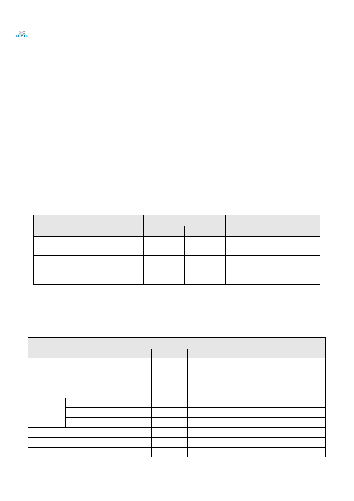
2.1 Limit parameter
Main parameter
Performance
Remark
Min.
Max.
Power supply(V)
0
3.8
Voltage over 3.8V will cause permanent
damage to module
Blocking power(dBm)
-
10
Chances of burn is slim when modules
are used in short distance
Operating temperature(℃)
-40
85
-
2.2 Operating parameter
Main parameter
Performance
Remark
Min.
Typ.
Max.
Operating voltage(V)
1.85
3.3
3.8
≥3.3V ensures output power
Communication level(V)
-
3.3
-
For 5V TTL, it may be at risk of burning down
Operating temperature(℃)
-40 - 85
Industrial design
Operating frequency(GHz)
420 - 450
Support ISM band
Power
consumption
TX current(mA)
-
100
-
Instant power consumption
RX current(mA)
-
17
-
-
Sleep current(μA)
- 1 -
Software is shut down
Max Tx power(dBm)
19.6
20.0
20.5
-
Receiving sensitivity(dBm)
-106.5
-107
-108
Air data rate is 1kbps
Air data rate(bps)
0.1k
-
2M
Controlled via user’s p rogramming
Page 5

Chengdu Ebyte Electronic Technology Co.,Ltd. E76-433M20S User Manual
Copyright ©2012–2018, Chengdu Ebyte Electronic Technology Co.,Ltd.
4
Main parameter
Description
Remark
Distance for reference
2500m
Test condition:clear and open area, antenna gain: 5dBi,
antenna height: 2.5m,air data rate: 1kbps
Crystal frequency
40MHz
-
Modulation
GFSK(recommended)
-
Package
SMD
-
Connector
1.27mm
Stamp hole
IC name
EFR32FG1P131F256GM48
-
FLASH
256 KB
-
RAM
32 KB
-
kernel
Cortex-M4
-
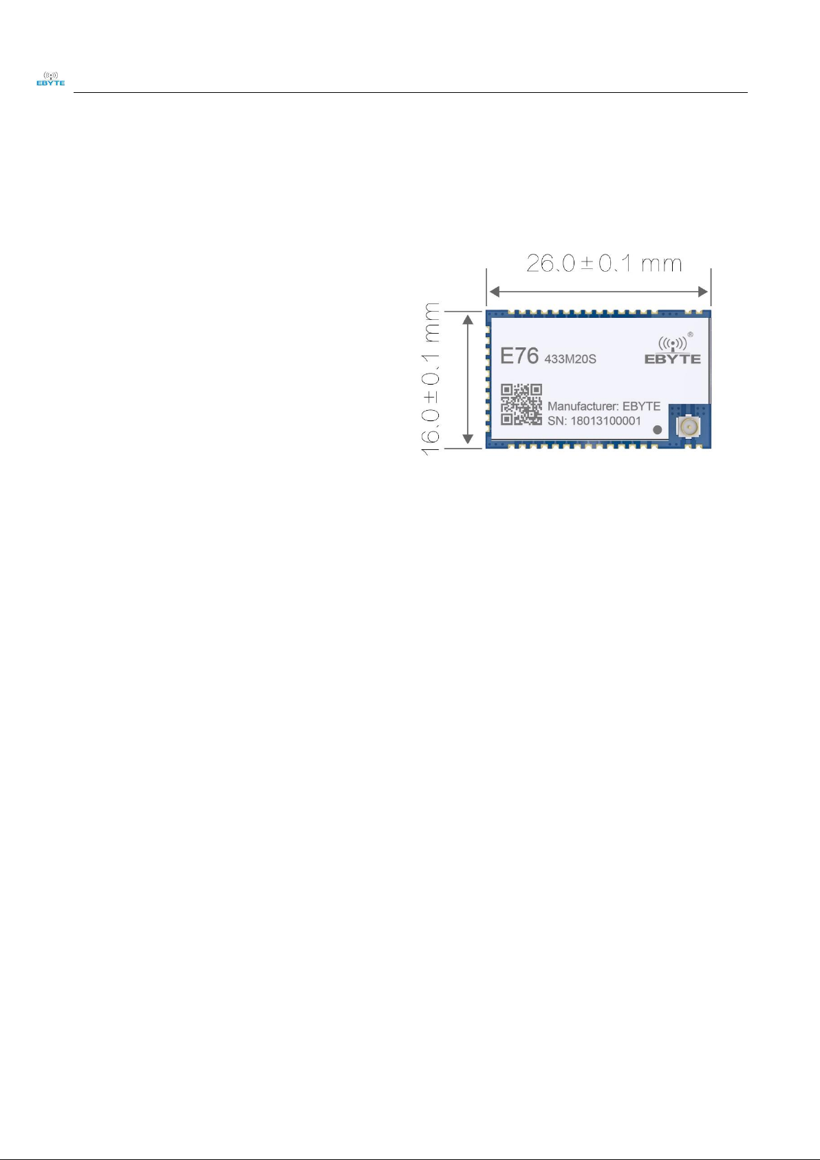
Size
16 * 26 mm
-
Antenna Interface
Stamp hole / IPEX
50 ohm impedance
3. Size and pin definition
Page 6

Chengdu Ebyte Electronic Technology Co.,Ltd. E76-433M20S User Manual
Copyright ©2012–2018, Chengdu Ebyte Electronic Technology Co.,Ltd.
5
No.
Name
Direction
Function
1
GND
Input/Output
Ground wire, connected to the power reference ground
2
GND
Input/Output
Ground wire, connected to the power reference ground
3
GND
Input/Output
Ground wire, connected to the power reference ground
4
RESETN
Input
Reset pin
5
PD9
Input/Output
Configurable universal IO p ort (see EFR32 manual for details)
6
PD10
Input/Output
Configurable universal IO p ort (see EFR32 manual for details)
7
PD11
Input/Output
Configurable universal IO p ort (see EFR32 manual for details)
8
PD12
Input/Output
Configurable universal IO p ort (see EFR32 manual for details)
9
PD13
Input/Output
Configurable universal IO p ort (see EFR32 manual for details)
10
PD14
Input/Output
Configurable universal IO p ort (see EFR32 manual for details)
11
PD15
Input/Output
Configurable universal IO p ort (see EFR32 manual for details)
12
PA0
Input/Output
Configurable universal IO p ort (see EFR32 manual for details)
13
PA1
Input/Output
Configurable universal IO p ort (see EFR32 manual for details)
14
PA2
Input/Output
Configurable universal IO p ort (see EFR32 manual for details)
15
PA3
Input/Output
Configurable universal IO p ort (see EFR32 manual for details)
16
GND
Input/Output
Ground wire, connected to the power reference ground
17
PA4
Input/Output
Configurable universal IO p ort (see EFR32 manual for details)
18
PA5
Input/Output
Configurable universal IO p ort (see EFR32 manual for details)
19
PB11
Input/Output
Configurable universal IO p ort (see EFR32 manual for details)
20
PB12
Input/Output
Configurable universal IO p ort (see EFR32 manual for details)
21
PB13
Input/Output
Configurable universal IO p ort (see EFR32 manual for details)
22
PB14
Input/Output
Configurable universal IO p ort (see EFR32 manual for details)
23
PB15
Input/Output
Configurable universal IO p ort (see EFR32 manual for details)
24
PC6
Input/Output
Configurable universal IO p ort (see EFR32 manual for details)
25
PC7
Input/Output
Configurable universal IO p ort (see EFR32 manual for details)
26
PC8
Input/Output
Configurable universal IO p ort (see EFR32 manual for details)
27
GND
Input/Output
Configurable universal IO p ort (see EFR32 manual for details)
28
PC9
Input/Output
Configurable universal IO p ort (see EFR32 manual for details)
29
PC10
Input/Output
Configurable universal IO p ort (see EFR32 manual for details)
30
PC11
Input/Output
Configurable universal IO p ort (see EFR32 manual for details)
31
PF0
Input/Output
Configurable universal IO p ort (see EFR32 manual for details)
32
PF1
Input/Output
Configurable universal IO p ort (see EFR32 manual for details)
33
PF2
Input/Output
Configurable universal IO p ort (see EFR32 manual for details)
34
PF3
Input/Output
Configurable universal IO p ort (see EFR32 manual for details)
35
PF4
Input/Output
Configurable universal IO p ort (see EFR32 manual for details)
36
PF5
Input/Output
Configurable universal IO p ort (see EFR32 manual for details)
37
PF6
Input/Output
Configurable universal IO p ort (see EFR32 manual for details)
38
PF7
Input/Output
Configurable universal IO p ort (see EFR32 manual for details)
39
VCC
Input/Output
power sup p ly positive reference, voltage range is 1.8V-3.8V.
40
GND
Input/Output
Ground wire, connected to the power reference ground
41
ANT
Input/Output
Antenna interface, st amp hole (50 ohm characteristic impedance)
Page 7

Chengdu Ebyte Electronic Technology Co.,Ltd. E76-433M20S User Manual
Copyright ©2012–2018, Chengdu Ebyte Electronic Technology Co.,Ltd.
6
42
GND
Input/Output
Ground wire, connected to the power reference ground
4. Basic Operation
4.1 Hardware Design
It is recommended to use DC stabilized power supply to s upply power to the module. The power s upply ripple
coefficient is as small as pos s ible, and the module needs to be reliably grounded.
Please pay attention to the correct connection of the positive and negative poles of the power s upply. If the reverse
connection is connected, the module may be permanently damaged.
Please check the power s upply to ensure that between the recommended s upply voltage, if exceeding the maximu m,
the module will be permanently damaged.
Please check the stability of the power s upply, the voltage can not be significantly frequent .
When designing the power s upply circuit for the module, it is often recommended to reserve more than 30% of the
margin, and the whole machine is beneficial for long -term stable operation.
The module should be as far away as poss ible from the power s upply, transformers, high -frequency wiring and other
parts with large electromagnetic interference.
High-frequency digital traces , high-frequency analog traces, and power traces must be avoided under the module. If
it is neces sary to pas s through the module, ass ume that the module is soldered to the Top Layer, and the copper is
spread on the Top Layer of the module contact part(All copper-covered and well grounded), and mus t be close to the
digital part of the module and routed in the Bottom Layer.
As suming the module is soldered or placed in the Top Layer, it is also wrong to randomly route the Bottom Layer or
other layers, which will affect the module's spurs and receiving s ensitivity to varying degrees .
As suming that there are devices with large electromagnetic interference around the module, the performance of t he
module will also be greatly affected. According to the intensity of the interference, it is suggested to stay away from
the module appropriately. If circumstances permit, appropriate isolation and shielding can be done.
As sume that there are traces with large electromagnetic interference around the module (high -frequency digital, high-
frequency analog, power trace), which will greatly affect the performance of the module. It is recommended to stay
away from the module according to the strength of the interference. If necess ary, appropriate isolation and shielding
can be done;
If the communication line uses a 5V level, a 1k-5.1k resistor must be connected in series (not recommended, there is
still a risk of damage).
Try to s tay away from some physical layers and also have a 2.4GHz TTL protocol, for example: USB3.0
The antenna mounting structure has a great influence on the performance of the module. It is necessary to ens ure that
the antenna is exposed, preferably vertically upward. When the module is mounted ins ide the case, use a good antenna
extension cable to extend the antenna to the outside of the case.
The antenna must not be installed ins ide the metal case, which will greatly reduce the transmission distance.
4.2 Software Programming
The core of this module is EFR32, Its driving mode is exactly the s ame as EFR3. Users can operate according to
EFR32 chip datas heet.
Burning program: The module is SoC with its own GPIO port, uses the J-LINK special downloader for program
Page 8

Chengdu Ebyte Electronic Technology Co.,Ltd. E76-433M20S User Manual
Copyright ©2012–2018, Chengdu Ebyte Electronic Technology Co.,Ltd.
7
download
Program download interface definition:
E76 pin
J-LINK interface
VCC
VCC
PF0
SWCLK
PF1
SWDIO
GND
GND
5. FAQ
5.1 Communication range is too short
The communication distance will be affected when obs tacle exists .
Data lose rate will be affected by temperature, humidity and co-channel interference.
The ground will abs orb and reflect wireless radio wave, so the performance will be poor when tes ting near ground.
Sea water has great ability in abs orbing wireless radio wave, so performance will be poor when testing near the sea.
The signal will be affected when the antenna is near metal object or put in a meta l case.
The signal will be affected when the antenna is near metal object or put in a metal case.
When the power supply at room temperature is lower than the recommended low voltage, the lower the voltage is,
the lower the transmitting power is.
Due to antenna quality or poor matching between antenna and module.
5.2 Module is easy to damage
Please check the power supply and ens ure it is within the recommended range. Voltage higher than the peak will lead
to a permanent damage to the module.
Please check the stability of power supply and ens ure the voltage not to fluctuate too much.
Please make sure anti-static measures are taken when installing and us ing, high frequency devices have electrostatic
susceptibility.
Please ensure the humidity is within limited range for some parts are sens itive to humidity.
Please avoid us ing modules under too high or too low temperature.
5.3 High bit error rate
There are co-channel signal interference nearby, keep away from interference sources or modify frequency, channel
to avoid interference.
Unsatisfactory power supply may also cause garbled characters, and ensure the reliability of the power supply.
If the extens ion cable or feeder is of poor quality or too long, the bit error rate will be high.
Page 9

Chengdu Ebyte Electronic Technology Co.,Ltd. E76-433M20S User Manual
Copyright ©2012–2018, Chengdu Ebyte Electronic Technology Co.,Ltd.
8
6. Welding operation guidance
6.1 Reflow Soldering Temperature
Profile Feature
Curve feature
Sn-Pb Assembly
Pb-Free Assembly
Solder Paste
solder paste
Sn63/Pb37
Sn96.5/Ag3/Cu0.5
Preheat Temperature min (Tsmin)
Minimum preheating t emperature
100℃
150℃
Preheat temperature max (Tsmax)
Maximum preheating t emperature
150℃
200℃
Preheat Time (Tsmin to Tsmax)(ts)
Preheating t ime
60-120 sec
60-120 sec
Average ramp-up rate(Tsmax to Tp)
Average rising rate
3℃/second max
3℃/second max
Liquidous Temperature (TL)
Liquid phase temperature
183℃
217℃
Time(tL)Maintained Above(TL)
Time above liquidus
60-90 sec
30-90 sec
Peak temperature(Tp)
Peak temperature
220-235℃
230-250℃
Aveage ramp-down rate(Tp to Tsmax)
Average descent rate
6℃/second max
6℃/second max
Time 25℃ to peak temperature
Time of 25 ° C to peak temperature
6 minutes max
8 minutes max
6.2 Reflow Soldering Curve
Page 10

Chengdu Ebyte Electronic Technology Co.,Ltd. E76-433M20S User Manual
Copyright ©2012–2018, Chengdu Ebyte Electronic Technology Co.,Ltd.
9
7. Related Model
Model
Chip
Frequency
Hz
Transmit
power
dBm
Test
distance
km
Air Data
rate
Packaging
Size
mm
Antenna
Type
E76-2G4M20S
EFR32
2.4G
20
2.5
0.1k~2M
SMD
17.5 *
28.7
PCB/IPEX
E76-868M20S
EFR32
868M
20
2.5
0.1k~2M
SMD
16 * 26
Stamp
hole/IPEX
E76-915M20S
EFR32
915M
20
2.5
0.1k~2M
SMD
16 * 26
Stamp
hole/IPEX
E76-433M20S
EFR32
433M
20
2.5
0.1k~2M
SMD
16 * 26
Stamp
hole/IPEX
8. Antenna Type
8.1 Antenna recommendation
The antenna plays an important role in the communication proces s . The inferior antenna often has a great impact on the
communication system. Therefore, we recommend some antennas that support our wireless modules and have excellent
performance and reasonable price.
Product
Type
Frequency
Hz
Interface
Gain
dBi
Size
Feeder
Features
TX433-NP-4310
Soft PCB
antenna
433M
SMA-J
2
43.8*9.5
mm
-
Built-in flexible FPC soft
antenna
TX433-JW-5
Rubber antenna
433M
SMA-J
2
50mm
-
Flexible, Omnidirectional
TX433-JWG-7
Rubber antenna
433M
SMA-J
2.5
75mm
-
Flexible, Omnidirectional
TX433-JK-20
Rubber antenna
433M
SMA-J
3
210mm
-
Flexible, Omnidirectional
TX433-JK-11
Rubber antenna
433M
SMA-J
2.5
110mm
-
Flexible, Omnidirectional
TX433-XP-200
Sucker antenna
433M
SMA-J
4
19cm
200cm
High Gain
TX433-XP-100
Sucker antenna
433M
SMA-J
3.5
18.5cm
100cm
High Gain
TX433-XPH-300
Sucker antenna
433M
SMA-J
6
96.5cm
300cm
High Gain
TX433-JZG-6
Rubber antenna
433M
SMA-J
2.5
52mm
-
Ultra short straight,
Omnidirectional
TX433-JZ-5
Rubber antenna
433M
SMA-J
2
52mm
-
Ultra short straight,
Omnidirectional
Page 11

Chengdu Ebyte Electronic Technology Co.,Ltd. E76-433M20S User Manual
Copyright ©2012–2018, Chengdu Ebyte Electronic Technology Co.,Ltd.
10
Revision history
Version
Date
Description
Issued by
1.00
2018/8/30
Original version
huaa
1.10
2018/9/28
Model No. sp lit
huaa
About us
Technical s upport: s upport@cdebyte.com
Documents and RF Setting download link: www.ebyte.com
Thank you for us ing Ebyte products! Please contact us with any questions or sugges tions: info@cdebyte.com
------------------- -- -- --- -- -- -- --- ----------------------------- -- -- --- -- -- --- -- ----------------Fax: 028-64146160 ext. 821
Web: www.ebyte.com
Address: Innovation Center D347, 4# XI-XIN Road,Chengdu, Sichuan, China
 Loading...