

Ebyte E70-433T14S2 User Manual

E70-433T14S2 User Manuel
CC1310 433MHz SMD Wireless Module

Chengdu Ebyte Electronic Technology Co,, Ltd E70-433T14S2 user manual
Copyright ©2012–2019,Chengdu Ebyte Electronic Technology Co.,Ltd 1
CONTENT
1.OVERVIEW .............................................................................................................................................. 3
1.1 INTRODUCTION ...................................................................................................................................................................................... 3
1.2 FEATURES ............................................................................................................................................................................................... 3
2. SPECIFICATION AND PARAMETER ................................................................................................. 4
2.1 LIMIT PARAMETER ................................................................................................................................................................................ 4
2.2 OPERATING PARAMETER ...................................................................................................................................................................... 4
3.Dimension/Pin Definition
................................................................................................................................................................. 5
4 CONNECT TO MCU ................................................................................................................................. 7
5 FUNCTION DESCRIPTION ..................................................................................................................... 8
5.1 FIXED TRANSMISSION........................................................................................................................................................................... 8
5.2 BROADCASTING TRANSMISSION ........................................................................................................................................................ 8
5.6.1 Indication of UART output
......................................................................................................................................................... 9
5.6.2 Indication of wireless transmitting
.......................................................................................................................................... 9
5.6.3 Configuration procedure of module
...................................................................................................................................... 10
6. OPERATING MODE ...............................................................................................................................11
6.1 MODE SWITCH ..................................................................................................................................................................................... 11
6.2 RSSI MODE (MODE 0) ....................................................................................................................................................................... 12
6.3 CONTINUOUS MODE (MODE 1) ........................................................................................................................................................ 13
6.4 SUB-PACKAGE MODE (MODE 2) ...................................................................................................................................................... 13
6.5 CONFIGURATION MODE (MODE 3) .................................................................................................................................................. 14
6.6 WAKE-UP MODE (MODE 4) .............................................................................................................................................................. 14
6.7 CONFIGURATION MODE (MODE 5) .................................................................................................................................................. 14
6.8 POWER SAVING MODE (MODE 6) .................................................................................................................................................... 15
6.9 SLEEP MODE (MODE 7) ..................................................................................................................................................................... 15
7.INSTRUCTION FORMAT ...................................................................................................................... 15
7.1 DEFAULT PARAMETER ....................................................................................................................................................................... 16
7.2 READING OPERATING PARAMETERS ............................................................................................................................................... 16
7.3 READING VERSION NUMBER ............................................................................................................................................................ 16
7.4 RESET INSTRUCTION .......................................................................................................................................................................... 16
7.5 PARAMETER SETTING INSTRUCTION .......................................................................................................................................... 17
8.PARAMETER SETTING ......................................................................................................................... 19
9.SECONDARY DEVELOPMENT ............................................................................................................ 19
9.1 DOWNLOAD PROGRAM ...................................................................................................................................................................... 20
10. HARDWARE DESIGN ......................................................................................................................... 21
11 FAQ ....................................................................................................................................................... 22
11.1 COMMUNICATION RANGE IS TOO SHORT ...................................................................................................................................... 22
11.2 MODULE IS EASY TO DAMAGE ........................................................................................................................................................ 22
11.3 BER(BIT ERROR RATE) IS HIGH .................................................................................................................................................... 22
12.PRODUCTION GUIDANCE ................................................................................................................. 23
12.1 REFLOW SOLDERING TEMPERATURE ............................................................................................................................................. 23
12.2 REFLOW SOLDERING CURVE ........................................................................................................................................................... 23
13.E70 SERIES ........................................................................................................................................... 24
14. ANTENNA GUIDANCE ........................................................................................................................ 24

Chengdu Ebyte Electronic Technology Co,, Ltd E70-433T14S2 user manual
Copyright ©2012–2019,Chengdu Ebyte Electronic Technology Co.,Ltd 2
14.1 ANTENNA RECOMMENDATION .................................................................................................................................................... 24
14.2 ANTENNA SELECTION..................................................................................................................................................................... 25
15.PACKAGE FOR BATCH ORDER ......................................................................................................... 25
REVISION HISTORY ................................................................................................................................ 26
ABOUT US ................................................................................................................................................. 26

Chengdu Ebyte Electronic Technology Co,, Ltd E70-433T14S2 user manual
Copyright ©2012–2019,Chengdu Ebyte Electronic Technology Co.,Ltd 3
1.Overview
1.1 Introduction
E70-433T14S2 wireless transceiver modules, operating at
425~450.5MHz (Default: 433MHz), is based on originally imported
CC1310(build-in dual core ARM) from TI, with TTL level output,
3.3V IO port voltage,24MHz industrial high-precision low-
temperature drift crystal vibration; Ensure its industrial ability and
stability.
The module features FEC (Forward Error Correction)
algorithm, which ensure its high coding efficiency & good
correction performance. In the case of sudden interference, it can
correct the interfered data packets proactively, so that the reliability
& transmission range are improved correspondingly. But without FEC, those data packets can only be dropped.
With built-in low power multifunctional wireless serial program, users can also conduct secondary development.
Accordingly.
1.2 Features
Communication distance tested is up to 1.5km
Maximum transmission power of 25mW, software multi-level adjustable;
Super low receiving current of 8mA;
Small size: 14x20mm;
Support RSSI;
Development based on CC1310, with dual core ARM;
Support the global license-free ISM 433MHz band;
Support air date rate of 2.5kbps~168kbps;
Low power consumption for battery supplied applications;
Can achieve up to 115200bps continuous frame unlimited-packet length transmission;
Support 2.2V~3.8V power supply, power supply over 3.3V can guarantee the best performance;
Industrial grade standard design, support -40 ~ 85 °C for working over a long time;
IPEX access point, stamp hole is optional, Facilitate user secondary development, facilitate integration.
1.3 Application
Home security alarm and remote keyless entry;
Smart home and industrial sensors;
Wireless alarm security system;
Building automation solutions;
Wireless industrial-grade remote control;
Health care products;
Advanced Meter Reading Architecture(AMI);
Automotive industry applications.

Chengdu Ebyte Electronic Technology Co,, Ltd E70-433T14S2 user manual
Copyright ©2012–2019,Chengdu Ebyte Electronic Technology Co.,Ltd 4
2. Specification and parameter
2.1 Limit parameter
Main parameter
Performance
Remark
Min.
Max.
Power supply(V)
0
3.8
Voltage over 3.8V will cause permanent
damage to module
Blocking power(dBm)
-
10
Chances of burn is slim when modules
are used in short distance
Operating temperature(℃)
-40
85
-
2.2 Operating parameter
Main parameter
Performance
Remark
Min
Typ.
Max.
Operating voltage(V)
2.2
3.3
3.8
≥3.3 V ensures output power
Communication level(V)
-
3.3
-
For 5V TTL, it may be at risk of
burning down
Operating temperature(℃)
-40 - 85
Industrial design
Operating frequency(MHz)
425 - 450.5
Support ISM band
Power
consumption
Transmitting current [mA]
-
36
-
Instant power consumption
Receiving current [mA]
- 8 -
-
Turn-off current [μA]
-
1.2
-
Software is shut down
Max Tx power(dBm)
13.6
14.0
15.3
-
Receiving sensitivity(dBm)
-107
-108
-109
Air data rate is 2.5kbps
Air data rate(bps)
2.5k
2.5k
168k
Controlled via user’s programming
Main parameter
Description
Remark
Distance for reference
1500m
Test condition:clear and open area, antenna gain: 5dBi,
antenna height: 2.5m,air data rate: 2.5kbps
TX length
Transmission mode specification
See transmission mode for details
Buffer
2048 Byte
-
Modulation
GFSK
-
Communication interface
UART
TTL
Package
SMD
-
Connector
1.27mm
-
Size
14*20mm
-
Antenna
IPX/Stamp hole
50 ohm impedance

Chengdu Ebyte Electronic Technology Co,, Ltd E70-433T14S2 user manual
Copyright ©2012–2019,Chengdu Ebyte Electronic Technology Co.,Ltd 5
3.Dimension/Pin Definition
No.
Pin item
Pin direction
Application
1、2、3
GND
Ground
Ground electrode
4、5、6、7
NC
Reserved pin
Reserved, to be floated
8
VCC
Voltage :2.2V ~ 3.8V DC
9、10
GND
Ground
Ground electrode
11
PA_EN
Reserved pin
Internal MCU controlled LNA pin, valid in high level, connect to pin 44
12
LNA_EN
Reserved pin
Internal MCU controlled PA pin, valid in high level, connect to pin 45
13
M2
Input
M2, M1, M0 jointly decide the 8 working modes;
An external 1k protective resistor shall be connected in series when in use.
14
RESET
Input
Reset pin, valid in low level
15
GND
Ground
Ground electrode
16
AUX
output
It is used to indicate the operation status of module, for user to wake up the
external MCU, the module outputs low level during self-checking and
Chengdu Ebyte Electronic Technology Co,, Ltd E70-433T14S2 user manual
Copyright ©2012–2019,Chengdu Ebyte Electronic Technology Co.,Ltd 6
initialization at power on, it can be configured as open-drain output or pull-up
output, please refer to parameter setting par. An external 1k protective
resistor shall be connected in series while using (can be floated)
17
TXD
Output
TTL serial port output connecting to external RXD input pin. It can be
configured as open-drain or push-pull input, please refer to Parameter setting.
An external 1k protective resistor shall be connected in series when in use.
18
TCKC
Input
JTAG TCKC
19
TMSC
Input
JTAG TMSC
20
RXD
Input
TTL serial port input connecting to external TXD pin. It can be configured as
open-drain or high pull input, please refer to Parameter setting. An external 1k
protective resistor shall be connected in series when in use.
21
M1
Input
M2, M1, M0 jointly decide the 8 working modes;
An external 1k protective resistor shall be connected in series and a 1M pullup resistor shall be added when in use.
(Cannot be floated, it can be grounded when not used)
22
M0
Input
M2, M1, M0 jointly decide the 8 working modes;
An external 1k protective resistor shall be connected in series and a 1M pullup resistor shall be added when in use.
(Cannot be floated, it can be grounded when not used)
23
GND
Ground
Ground electrode
24
ANT
Antenna (50Ω characteristic impedance)
This product can achieve Pin compatibility, Pin to Pin replacement
The single-chip microcomputer control PA LNA truth value table is as follows:
PA_EN
LNA_EN
Transmitting 1 0
Receiving 0 1
Sleeping 0 0
Chengdu Ebyte Electronic Technology Co,, Ltd E70-433T14S2 user manual
Copyright ©2012–2019,Chengdu Ebyte Electronic Technology Co.,Ltd 7
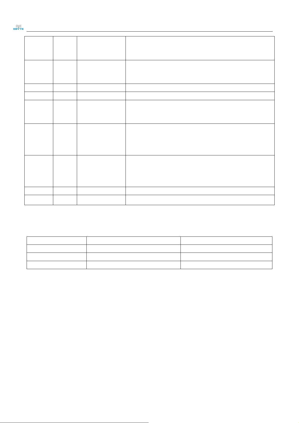
4 Connect to MCU
No.
Description(STM8L MCU)
1
The UART module is TTL level., please collect with MCU.
2
For some MCU works at 5VDC, it may need to add 4-10K pull-up resistor for the TXD & AUX pin.
Chengdu Ebyte Electronic Technology Co,, Ltd E70-433T14S2 user manual
Copyright ©2012–2019,Chengdu Ebyte Electronic Technology Co.,Ltd 8
5 Function description
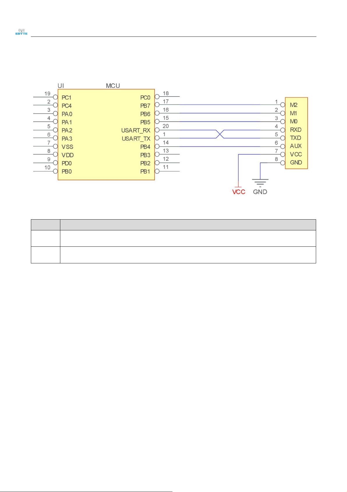
5.1 Fixed transmission
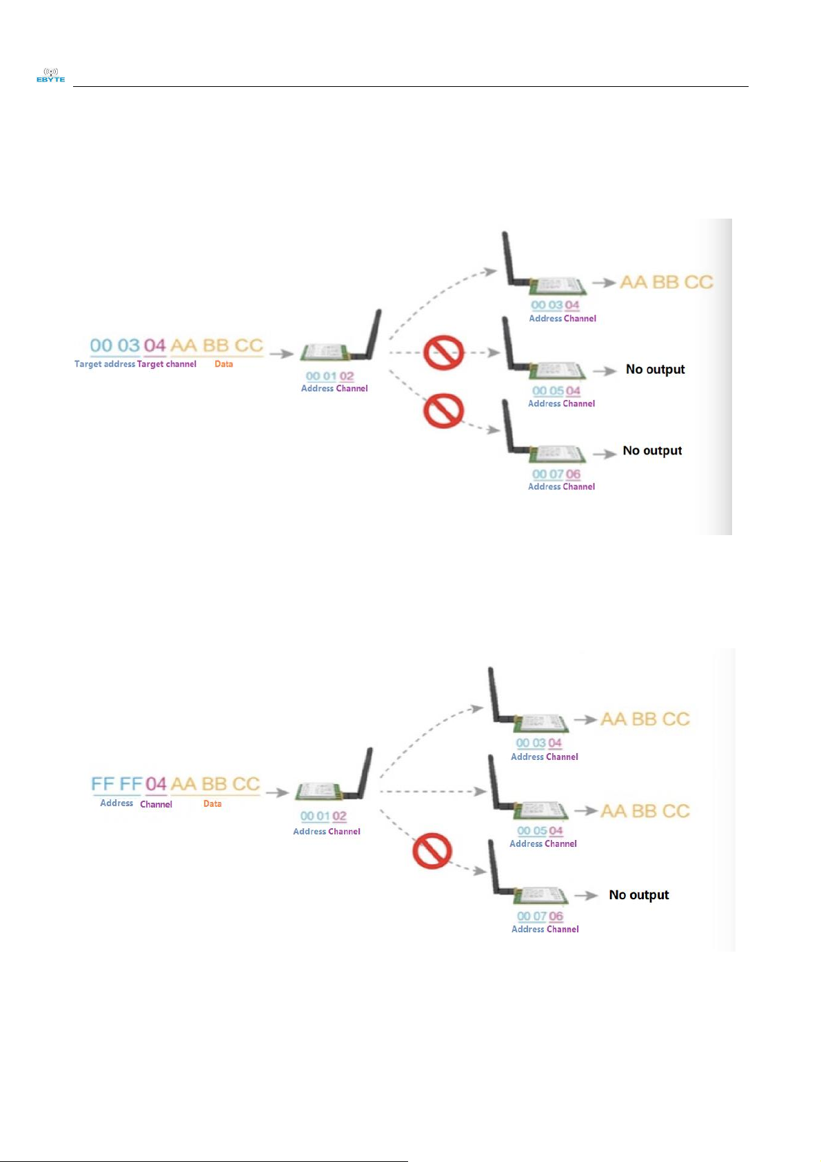
5.2 Broadcasting transmission
5.3 Broadcasting address
For example: Set the address of module A as 0xFFFF or 0x0000, and the channel as 0x04;
When module is the transmitter (transparent transmission), all modules under channel 0x04 will receive the data, the
 Loading...