

Page 1

E70-433NW30S User Manual
433MHz 1W Star Network SMD Wireless Module
Page 2

Chengdu Ebyte Electronic Technology Co,;Ltd E70-433NW30S user manual
CONTENT
1. OVERVIEW ....................................................................................................................................................... 2
1.1 INTRODUCTION ............................................................................................................................................... 2
1.2 FEATURES ............................................................................................................................................................ 2
2. SPECIFICATION AND PARAMETER .......................................................................................................... 3
2.1 LIMIT PARAMETER ................................................................................................................................................ 3
2.2 OPERATING PARAMETER........................................................................................................................................ 3
3 SIZE AND PIN DEFINITION ............................................................................................................................... 4
4 CONNECT TO MCU ............................................................................................................................................. 7
5 FIRMWARE TRANSMITTING MODE ............................................................................................................. 7
5.1 TRANSPARENT TRANSMISSION ............................................................................................................................. 7
5.2 SHORT ADDRESS TRANSMISSION ................................ .......................................................................................... 7
5.3 LONG ADDRESS TRANSMISSION............................................................................................................................ 8
6.DEVICE STATUS ................................................................................................................................................... 8
6.1 AUX DESCRIPTION ............................................................................................................................................... 8
6.2 LINK DESCRIPTION .............................................................................................................................................. 9
6.3 ACK DESCRIPTION ..............................................................................................................................................10
7.OPERATING MODE ........................................................................................................................................... 10
DORMANT NODE .......................................................................................................................................................10
7.1.COORDINATOR MODE ...........................................................................................................................................10
7.2.NORMAL NODE .................................................................................................................................................... 11
7.3.DORMANT NODE .................................................................................................................................................. 11
7.4 CONFIGURATION MODE ...................................................................................................................................... 11
7.5 MODE SWITCHING ............................................................................................................................................... 11
8.QUICK START ..................................................................................................................................................... 12
8.1 COMMUNICATION BETWEEN NORMAL NODE AND COORDINATOR ............................................................................12
9. ATC COMMAND ................................................................................................................................................ 15
10. HARDWARE DESIGN ..................................................................................................................................... 20
11 FAQ ...................................................................................................................................................................... 21
11.1 COMMUNICATION RANGE IS TOO SHORT ..............................................................................................................21
11.2 MODULE IS EASY TO DAMAGE .............................................................................................................................22
11.3 BER(BIT ERROR RATE) IS HIGH ..........................................................................................................................22
12.PRODUCTION GUIDANCE ............................................................................................................................ 22
12.1.REFLOW SOLDERING TEMPERATURE................................ ...................................................................................22
12.2 REFLOW SOLDERING CURVE ............................................................................................................................23
13. E70 SERIAL ....................................................................................................................................................... 23
14. ANTENNA RECOMMENDATION ................................................................................................................. 23
15. PACKAGE FOR BATCH ORDER .................................................................................................................. 24
REVISION HISTORY ............................................................................................................................................ 25
ABOUT US ............................................................................................................................................................... 25
Copyright ©2012–2019,Chengdu Ebyte Electronic Technology Co,;Ltd 1
Page 3
Chengdu Ebyte Electronic Technology Co,;Ltd E70-433NW30S user manual
1. Overview
1.1 Introduction
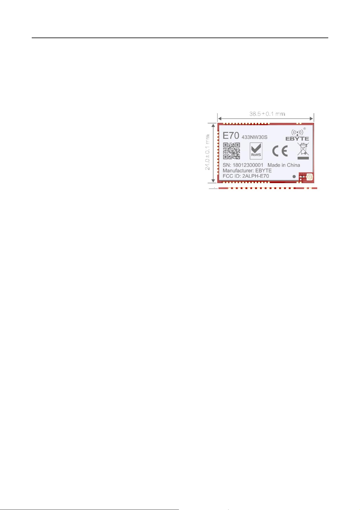
E70-433NW30S is the star network module, operating at
433MHz, based on originally imported TI CC1310 and 15.4-Stack
protocol, with coordinator and terminal as a whole. The module
features with long range and high-speed transmission modes.
Maximum 200 nodes can send data to one coordinator. Use
industry-standard AT commands for operating configuration, which
greatly simplifies user operations. With stable batch production, the
module is suitable for various wireless communication network
applications.
E70-433NW30S is the first 433MHz wireless module which meets IEEE 802.15.4 in China and solves a series of
problems caused by the traditional 433MHz module. Users will no longer spend more effort to deal with complex network
protocols, which greatly reduces the difficulty of customer development and shortens the user's development cycle. The
protocol guarantees the stability and packet rate of the entire wireless communication system.
E70-433NW30S strictly follows design standards of FCC, CE, CCC and meets various RF certification requirements
for exporting.
1.2 Features
Communication distance tested is up to 6.5km
Maximum transmission power of 1W, software multi-level adjustable;
Support the global license-free ISM 433MHz band;
Support air date rate of 5kbps~50kbps;
Support CSMA/CA, Carrier multi - channel interception technology which can avoid collision effectively
Maximum 200 nodes, no need to deal with complicated protocol.
Adopting AES128 data encryption, Ensure the reliability of data packets.
Supports DSSS technology, like LoRa, better than GFSK.
Low power consumption for battery supplied applications;
Can achieve up to 115200bps continuous frame unlimited-packet length transmission
Support 3.3V~5.2V power supply, power supply over 3.3V can guarantee the best performance;
Industrial grade standard design, support -40 ~ 85 °C for working over a long time;
IPEX access point, stamp hole is optional, facilitate user secondary development, facilitate integration.
1.3 Application
Copyright ©2012–2019,Chengdu Ebyte Electronic Technology Co,;Ltd 2
Page 4

Chengdu Ebyte Electronic Technology Co,;Ltd E70-433NW30S user manual
Main parameter
Performance
Remarks
Min.
Max.
Power supply(V)
0
5.2
Voltage over 5.2V will cause permanent
damage to module
Blocking power(dBm)
-
10
Chances of burn is slim when modules
are used in short distance
Operating temperature(℃)
-40
85
Main parameter
Performance
Remark
Min
Typ.
Max.
Operating voltage(V)
3.3
5.0
5.2
5.0V is recommended
Communication level(V)
3.3
For 5V TTL, it may be at risk of
burning down
Operating temperature(℃)
-40 - 85
Industrial design
Operating frequency(MHz)
431 - 446.5
Support ISM band
Power
consumption
Transmitting current [mA]
610
Instant power consumption
Receiving current [mA]
13
Turn-off current [μA]
2
Software is shut down
Max Tx power(dBm)
29.6
30.0
31.3
Receiving sensitivity(dBm)
-109
-110
-111
Air data rate is 5kbps
Air data rate(bps)
5k
5k
50k
Controlled via user’s programming
Home security alarm and remote keyless entry;
Smart home and industrial sensors;
Wireless alarm security system;
Building automation solutions;
Wireless industrial-grade remote control;
Health care products;
Advanced Meter Reading Architecture(AMI);
Automotive industry applications.
2. Specification and parameter
2.1 Limit parameter
2.2 Operating parameter
Copyright ©2012–2019,Chengdu Ebyte Electronic Technology Co,;Ltd 3
Page 5
Chengdu Ebyte Electronic Technology Co,;Ltd E70-433NW30S user manual
Main parameter
Description
Remark
Distance for reference
6500m
Test condition:clear and open area, antenna gain: 5dBi,
antenna height: 2.5m,air data rate: 5kbps
TX length
Transmission mode specification
See transmission mode for details
Buffer
512 Byte
A single packet may not exceed 128 bytes
Modulation
GFSK
Communication interface
UART
Package
SMD
Connector
1.27mm
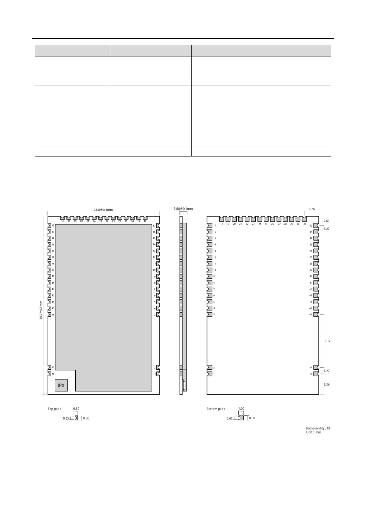
Size
24*38.5mm
Antenna
IPX/Stamp hole
50 ohm impedance
3 Size and pin definition
Copyright ©2012–2019,Chengdu Ebyte Electronic Technology Co,;Ltd 4
Page 6

Chengdu Ebyte Electronic Technology Co,;Ltd E70-433NW30S user manual
No.
Pin item
Pin direction
Application
1
GND
Ground
Ground electrode
2
GND
Ground
Ground electrode
3
GND
Ground
Ground electrode
4
NC
Reserved pin
Reserved, to be floated
5
NC
Reserved pin
Reserved, to be floated
6
NC
Reserved pin
Reserved, to be floated
7
NC
Reserved pin
Reserved, to be floated
8
NC
Reserved pin
Reserved, to be floated
9
NC
Reserved pin
Reserved, to be floated
10
NC
Reserved pin
Reserved, to be floated
11
NC
Reserved pin
Reserved, to be floated
12
NC
Reserved pin
Reserved, to be floated
13
NC
Reserved pin
Reserved, to be floated
14
NC
Reserved pin
Reserved, to be floated
15
NC
Reserved pin
Reserved, to be floated
16
LINK
output
For indicating the current network connection status of the module, it can be
configured as drain open circuit output or push-pull output. For details, please refer
to the parameter setting, a 1K protection resistor shall be connected in series
externally (it can be suspended).
17
GND
Ground
Ground electrode
18
NC
Reserved pin
Reserved, to be floated
19
NC
Reserved pin
Reserved, to be floated
20
NC
Reserved pin
Reserved, to be floated
21
NC
Reserved pin
Reserved, to be floated
22
TCKC
Input
JTAG TCKC
23
TMSC
Input
JTAG TMSC
24
RESET
Input
Module reset pin, low level effective
25
NC
Reserved pin
Reserved, to be floated
26
M0
Input
M1M0 The four working modes of the module are determined by the joint
combination. When in use, a 1K protection resistor shall be connected in series
externally, and a 1M pull-up resistor shall be added (it shall not be suspended,
otherwise, it can be grounded).
27
M1
Input
M1M0 The four working modes of the module are determined by the joint
combination. When in use, a 1K protection resistor shall be connected in series
externally, and a 1M pull-up resistor shall be added (it shall not be suspended,
otherwise, it can be grounded).
28
VCC
Power supply:2.6V ~ 5.5V DC
29
VCC
Power supply :2.6V ~ 5.5V DC
30
GND
Ground
Ground electrode
31
GND
Ground
Ground electrode
32
ACK
Output
The user indicates the data transmission result of the module, which is pulled down
Copyright ©2012–2019,Chengdu Ebyte Electronic Technology Co,;Ltd 5
Page 7

Chengdu Ebyte Electronic Technology Co,;Ltd E70-433NW30S user manual
before transmission and pulled up after success. It can be configured as drain open
circuit output or push-pull output. When it is used, a 1K protection resistor should be
connected externally in series (it can be suspended).
33
NC
Reserved pin
Reserved, to be floated
34
NC
Reserved pin
Reserved, to be floated
35
NC
Reserved pin
Reserved, to be floated
36
RXD
Input
TTL UART inputs, connects to external (MCU, PC) TXD output pin. Can be
configured as open-drain or pull-up input.
37
TXD
Output
TTL UART outputs, connects to external RXD (MCU, PC) input pin. Can be
configured as open-drain or push-pull output
38
AUX
Output
To indicate module ’ s working status & wakes up the external MCU. During the
procedure of self-check initialization, the pin outputs low level. Can be configured as
push-pull output (suspending is allowed).
39
NC
Reserved pin
Reserved, to be floated
40
NC
Reserved pin
Reserved, to be floated
41
NC
Reserved pin
Reserved, to be floated
42
PA_EN
Output
Internal single chip microcomputer control PA pin, high level effective, connected 45
pin
43
LNA_EN
Output
Internal single chip microcomputer control LNA pin, high level effective, connected
44 pin
44
LNA_EN
Input
Internal single chip microcomputer control LNA pin, high level effective, connected
43 pin
45
PA_EN
Input
Internal single chip microcomputer control PA pin, high level effective, connected 42
pin
46
GND
Ground
Ground electrode
47
GND
Ground
Ground electrode
48
ANT
Antenna 50 ohm impedance
This product can achieve Pin compatibility, Pin to Pin replacement
Copyright ©2012–2019,Chengdu Ebyte Electronic Technology Co,;Ltd 6
Page 8

Chengdu Ebyte Electronic Technology Co,;Ltd E70-433NW30S user manual
No.
Description(STM8L MCU)
1
The UART module is TTL level., please collect with MCU.
2
For some MCU works at 5VDC, it may need to add 4-10K pull-up resistor for the TXD & AUX pin.
Format
Values
When the coordinator is set to transparent transmission, the coordinator will send broadcast message. At this time, all non-dormant nodes in the entire
network will receive data.
Format
Values
Coordinator short address transmission format: short address + valid data 00 00 or FF FF are broadcast address
Coordinator
HEX
Sending:00 01 AA BB CC
Node A address 00 01
HEX
Receiving:AA BB CC
Node B address 00 02
HEX
Null
Node C address 00 03
HEX
Null
Coordinator
HEX
FF FF AA BB CC
Node A address 00 01
HEX
AA BB CC
4 Connect to MCU
5 Firmware Transmitting mode
5.1 Transparent transmission
5.2 Short address transmission
Copyright ©2012–2019,Chengdu Ebyte Electronic Technology Co,;Ltd 7
Page 9

Chengdu Ebyte Electronic Technology Co,;Ltd E70-433NW30S user manual
Node B address 00 02
HEX
AA BB CC
Node C address 00 03
HEX
AA BB CC
Format
Values
Coordinator short address transmission format: short address + valid data
00 00 00 00 00 00 00 00 00 or FF FF FF FF FF FF FF FF are broadcast address;
Coordinator
HEX
Sending:0A 01 AA 45 65 13 12 44 AA BB CC
Node A address:
0A 01 AA 45 65 13 12 44
HEX
Receiving:AA BB CC
Node B address:
0D 55 18 42 1A 27 29 64
HEX
Null
Node C address:
A4 78 02 46 B5 1C 5A 02
HEX
Null
Coordinator
HEX
FF FF FF FF FF FF FF FF AA BB CC
Node A address:
0A 01 AA 45 65 13 12 44
HEX
AA BB CC
Node B address:
0A 01 AA 45 65 13 12 44
HEX
AA BB CC
Node C address:
0A 01 AA 45 65 13 12 44
1 HEX
AA BB CC
No
Description(STM8L MCU)
1
The UART module is TTL level.
2
For some MCU works at 5V DC, it may need to add 4-10K pull-up resistor for the TXD & AUX pin.
No.
Description
5.3 Long address transmission
6.Device status
6.1 AUX description
It can indicate whether there are data that are yet to send via wireless way, or whether all wireless data has been sent through
UART, or whether the module is still in the process of self-check initialization.
Copyright ©2012–2019,Chengdu Ebyte Electronic Technology Co,;Ltd 8
Page 10

Chengdu Ebyte Electronic Technology Co,;Ltd E70-433NW30S user manual
1
【Indication of UART output】can be used to wake up external MCU.
2
【Indication of wireless transmitting】
1.The length of the buffer is 512 bytes, and the single packet must not exceed 128 bytes,
when Aux=1, users can transmit data continuously within 128 bytes.
2.When AUX = 1, it means that all the UART data of the module have been transmitted already.
6.2 LINK description
The LINK pin indicates the current network status, after the node is connected to the network, the current pin is pulled
Copyright ©2012–2019,Chengdu Ebyte Electronic Technology Co,;Ltd 9
low. The external device can query the device network status through the pin level. In the coordinator mode, the pin
indicates if the module establishes the network normally.
Page 11

Chengdu Ebyte Electronic Technology Co,;Ltd E70-433NW30S user manual
M1
M0
Description
Remarks
Coordinator mode
0
0
Set up a network to manage network node
information
Transfer data according to input and output modes
Normal node
0
1
Send and receive data at any time
High real-time performance
Dormant node
1
0
Low-power reception, sending data at any
time
Receive delay, send need to wake up the serial port
Sleep mode
1
1
Cannot send and receive data, system sleeps
The fixed baud rate is 115200 8N1
6.3 ACK description
The ACK pin is used to indicate the status of the last user’s data transmission. Before transmitting, the pin is pulled
low. After the transmission is successful, the pin is pulled high. The user can use this pin state to judge if the data has
arrived successfully. This pin function cannot indicate the coordinator to send broadcast message.
Note: In 802.15.4 protocol, the device will use the CSMA/MA technology to access the channel before sending data.
When the receiving device receives the data, the returned ACK does not have this mechanism. This means that even
if the receiving device can receive data in extreme conditions, sending device ACK pin indicates that the last data
transmission failed.
7.Operating mode
7.1.Coordinator mode
If the user configures the operating mode 4,(M0=0,M1=0)or the user configures the operating mode as 0, the
module works in the coordinator mode. In the coordinator mode, the coordinator can set up the network, coordinator is
the central node of the network, there must be a coordinator in the network.
The coordinator configurable data input mode is:
Broadcast transmission. When configured to broadcast, all non-dormant devices on the entire network will receive data.
The ACK pin indicates transmission successfully all the time.
Short address transmission, when configured to short address transmission, the user must specify the short address before
sending data.
Long address transmission. When configured to long address transmission, the user must specify the long address before
Copyright ©2012–2019,Chengdu Ebyte Electronic Technology Co,;Ltd 10
Page 12

Chengdu Ebyte Electronic Technology Co,;Ltd E70-433NW30S user manual
No
Remarks
1
The user can decide the operating mode by the combination of M1 and M0
2
In any work mode, the user can configure the operating mode through the AT command
3
When M0=1,M1=1, the serial port parameters are 115200, 8N1(fixed)
sending data.
7.2.Normal node
If the user configures the operating mode 4, (M0=0,M1=1)or the user configures the operating mode as 1, the module
works in the normal node mode. In the normal node mode, the data can be received and sent in real time. It is suitable for
application with low power consumption but high real-time requirement.
7.3.Dormant node
If the user configures the operating mode as 4, M0=1,M1=0, or the user configures the operating mode as 2, the module
works in the dormant node mode, the device request if there is data transmitted by coordinator according to the userconfigured sleep period , The non-broadcast data sent by the coordinator will be temporarily stored inside the coordinator.
The device is in low power consumption during the sleep period. If the sleep node wants to send data actively, the user
should send no more than two bytes to wake up the device. After the byte data is used to wake up the device and the wakeup byte is sent, the user needs to wait for more than 100ms to send the real data. After the wake-up byte is sent, the user
needs to wait for 100ms to send the real data and the wake-up data will be discarded. After the device was waken up, the
module will open the serial port, receiving AT command, if more than 2 seconds, there is no data input, the module will
close serial port and go to sleep.The sleep node is suitable for applications where the user requires high power consumption
but does not require high real-time data.
7.4 Configuration mode
When M0=1,M1=1,the device will switch to configuration mode. In the this mode, the serial port parameters are:
115200, 8N1, and the average operating current is 2uA. In this mode, the module cannot send and receive data. When the
external AT instruction is configured, needs the serial port to send no more than two bytes data to wake up the device .After
the wake-up byte is sent, the user needs to wait for 100ms to send the real data and the wake-up data will be discarded.
After the device was waken up, the module will open the serial port, receiving AT command, if more than 2 seconds, there
is no data input, the module will close serial port and go to sleep. The next AT command requires the user to resend the
wake-up byte.
7.5 Mode switching
Copyright ©2012–2019,Chengdu Ebyte Electronic Technology Co,;Ltd 11
Page 13

Chengdu Ebyte Electronic Technology Co,;Ltd E70-433NW30S user manual
8.Quick start
8.1 Communication between normal node and coordinator
Coordinator configuration
Open the serial port assistant, select the serial port corresponding to the device, and set the serial port parameters
(default is 115200, 8N1)
Enter "+++" without line breaks to enter the AT command mode. When receiving "Enter AT Mode", the AT mode is
successfully entered. As shown in Figure 5-1:
Enter "AT+HELP" with line breaks to see all instructions. As shown in Figure 1:
Figure 1
Then enter "AT+WMCFG=0" with line breaks to configure the device as the coordinator mode, as shown in Figure 2:
Figure 2
Then enter “AT+RSTART” to restart the device with a line break. The coordinator configuration is complete. As
Copyright ©2012–2019,Chengdu Ebyte Electronic Technology Co,;Ltd 12
Page 14

Chengdu Ebyte Electronic Technology Co,;Ltd E70-433NW30S user manual
shown in Figure 3:
Figure 3
Normal node configuration
Open the serial port assistant and select the serial port corresponding to the device. Set the baud rate to 115200, the
data bit to 8 bits, the parity bit to none, the stop bit to 1 bit, and the flow control is disabled, open the serial port.
Enter "+++" without line breaks to enter the AT command mode. When receiving “Enter AT Mode", the AT mode is
successfully entered.
Enter "AT+HELP" with line breaks to see all instructions. As shown in Figure 4:
Figure 4
Then enter "AT+WMCFG=1" with line breaks to configure the device as the coordinator mode, as shown in Figure
5:
Figure 5
Then enter “AT+RSTART” to restart the device with a line break. The coordinator configuration is complete.
As shown in Figure 5-6:
Copyright ©2012–2019,Chengdu Ebyte Electronic Technology Co,;Ltd 13
Page 15

Chengdu Ebyte Electronic Technology Co,;Ltd E70-433NW30S user manual
Figure 6
Network transmission data transmission
When the configuration is complete, the coordinator restarts and the DIO11 pin is asserted low, indicating that the
coordinator has started and is running. After an normal node device starts up, it will have a network access time of 10
to 20 seconds. When the network access is completed, the DIO11 pin will be set to low level, indicating that the network
access is successful.
After waiting for the device to access the network successfully, the coordinator enters to AT mode, enters the command
"AT+DINFO=ALLNODE" with a newline character, the coordinator will return the short address and long address of
all the nodes that have already entered the network and recorded. As shown in Figure 5-7:
Figure 7
At this time, use “AT+EXIT” to exit the AT command mode with a newline character, and reclaim “Exit AT Mode”
to exit AT mode. Next can transfer data, as shown in Figure 8:
Figure 8
The coordinator and node devices can communicate with each other normally.
Copyright ©2012–2019,Chengdu Ebyte Electronic Technology Co,;Ltd 14
Page 16

Chengdu Ebyte Electronic Technology Co,;Ltd E70-433NW30S user manual
1
Enters” +++” into AT Command
+++
Parameter Description:
Nonparametric
Response:
Enter AT Mode
Example:+++
Note: 1. The AT command can be used only after entering the AT command mode
2. After entering the AT command mode, the AT command mode can be used again only after exiting the AT command mode, reset or
restart the module
3. When writing this instruction, the serial debugging assistant must be set not to send new lines; writing other AT commands must be set
to send new lines.
2
AT+EXIT Exit AT command mode
AT+EXIT
Parameter Description:
Null
Response:
Exit AT Mode
Example:AT+EXIT
Note: AT commands are invalid after exiting AT command mode
3
AT+HELP Help command
AT+HELP
Parameter Description:
Null
Response:
All instructions and help information
Example:AT+HELP
4
AT+ WMCFG Setting /Querying working mode (reboot valid)
AT+ WMCFG =?
Description:
Gets working mode
Response:
WMCFG:4
AT+ WMCFG =Value
Description:
Value:0~4
0,Coordinator;
1, Normal node;
9. AT Command
When the serial port enters AT mode, it needs to open the serial port assistant, set the serial port (default parameter) baud
rate 115200, data bit 8 bit, stop bit 1 bit, open the serial port, input "+++" without carriage return. All parameter settings
will reply "\r\n+OK\r\n".
Copyright ©2012–2019,Chengdu Ebyte Electronic Technology Co,;Ltd 15
Page 17

Chengdu Ebyte Electronic Technology Co,;Ltd E70-433NW30S user manual
2, Dormant Node;
3, Sleep mode;
4, (factory default), dial switch control
Example:AT+ WMCFG =4
Note: 1. After setting a new mode, it needs to be reset or power off and restart
5
AT+DINFO Get facility information
AT+DINFO=ALLNODE
Description:
Query the short and long address of all node, and return by UART.
It works only when the device works in the coordinator mode
AT+DINFO=SELFS
Description:
Get short address and return by UART
AT+DINFO=SELFE
Description:
Get long address and return by UART
Example:AT+DINFO=SELFE
6
AT+ TFOCFG Setting/Querying output format configuration (reboot valid)
AT+ TFOCFG=?
Description:
Gets output format configuration
Response:
TFOCFG:0
AT+ TFOCFG=Value
Description:
Value:0~7
0:Output: valid data (transparent transmission))
1: Output: Valid Data +Long Address
2:Output: Valid Data +Short Address
3:Output: Valid Data+RSSI
4:Output:Valid Data+Long Address+Short Address
5:Output:Valid Data+Long Address+RSSI
6:Output:Valid Data+Short Address+RSSI
7:Output:Valid Data+Long Address+Short Address+RSSI
Example:AT+ TFCFG=0
7
AT+ TFICFG Setting/Querying input transmission format configuration (reboot valid)
AT+ TFICFG=?
Description:
Gets input transmission format configuration
Response:
TFICFG:0
AT+ TFICFG=Value
Description:
Copyright ©2012–2019,Chengdu Ebyte Electronic Technology Co,;Ltd 16
Page 18

Chengdu Ebyte Electronic Technology Co,;Ltd E70-433NW30S user manual
(This instruction is valid for coordinator
only)
Value:0~2
0:Input Broadcast(Only the coordinator works)
1:Input Short Address+Data (0x0000 0xfff) are broadcast address
2:Input Long Address+Data
(0x000000000000 0xffffffffffffffff)are broadcast address
Example:AT+TFICFG=0
8
AT+TMCFG Setting/Querying transport mode configuration (reboot valid)
AT+TMCFG=?
Description:
Gets transport mode configuration
Response:
TMCFG:0
AT+TMCFG=Value
Description:
Value:0 or 1
0:Long Range mode,LRM
1:Standard transmission mode,GFSK
Example:AT+TMCFG=0
Note: The coordinator and node should have the same transmission mode before they can access the network.
9
AT+ PIDCFG Setting/Querying PANID configuration(reboot valid)
AT+PIDCFG=?
Description:
Gets PANID configuration
Response:
PIDCFG:65535
AT+PIDCFG=Value
Description:
Value:0~65535
Example:AT+PIDCFG=65535
Note: The node can only join the same network as its PANID (any network can be added when it is configured as 65535)
10
AT+ DMCFG Setting/Querying dormancy time configuration(reboot valid)
AT+DMCFG=?
Description:
Gets dormancy time configuration
Response:
DMCFG:0~60
AT+DMCFG=Value
Description: Configure wakeup period of sleep node
Value: dormant time, per unit second (S). 0~60 S.
Note: When configured as 0, the node will never wake up, that is, the node cannot receive
data but can upload data
Example:AT+DMCFG=0
11
AT+RSCFG Setting/Querying the reboot parameter configuration
Copyright ©2012–2019,Chengdu Ebyte Electronic Technology Co,;Ltd 17
Page 19

Chengdu Ebyte Electronic Technology Co,;Ltd E70-433NW30S user manual
(reboot valid)
AT+RSCFG=?
Description:
Gets the reboot parameter configuration
Response:
RSCFG:0
AT+RSCFG=Value
Description:
Value:0 or 60~65535(S)
When the value less than 60s, the system judges 60, equals 0s, does not restart
Example:AT+RSCFG=0
Note: This parameter can be used for node disconnection detection. It is recommended to open it.
12
AT+UBCFG Setting /Querying the baud rate parameter (reboot valid)
AT+UBCFG=?
Description:
Obtains the baud rate parameter
Response:
UBCFG:7
AT+UBCFG=Value
Description:
Value:0~7
0:1200
1:2400
2:4800
3:9600
4:19200
5:38400
6:57600
7:115200
Example:AT+UBCFG=7
13
AT+UPCFG Setting /Querying the device parity parameter (reboot valid)
AT+UPCFG=?
Description
Gets the device parity parameter
Response:
UPCFG:0
AT+UPCFG=Value
Description:
Value:0~2
0:None
1:Odd parity
2:Even parity
Copyright ©2012–2019,Chengdu Ebyte Electronic Technology Co,;Ltd 18
Page 20

Chengdu Ebyte Electronic Technology Co,;Ltd E70-433NW30S user manual
Example:AT+UPCFG=0
14
AT+PWCFG Setting /Querying the power parameter(reboot valid)
AT+PWCFG=?
Description:
Gets the power parameter
Response:
PWCFG:3
AT+PWCFG=Value
Description:
Value:0~3
0:Polar Altitude
1:High
2:Medium
3:Low
Example:AT+ PWCFG=3
15
AT+IOCFG Setting /Querying the IO parameter
AT+IOCFG=?
Description:
Gets the IO parameter
Response:
IOCFG:0
AT+IOCFG=Value
Description:
Value:0 or 1
0:Push-pull
1:open-drain
Example:AT+IOCFG=0
16
AT+DFCFG Restore the default parameter
AT+DFCFG
Description:Null
Restore the default parameter
Example:AT+DFCFG
17
AT+RSTART Device Restart
AT+RSTART
Description:Null
Device Restart
Example:AT+RSTART
18
AT+ECHO Sets up the AT instruction to turn off the back display
AT+ECHO=Value
Description:
Value:0 or 1
1:Close the echo
0:Open the echo
Copyright ©2012–2019,Chengdu Ebyte Electronic Technology Co,;Ltd 19
Page 21

Chengdu Ebyte Electronic Technology Co,;Ltd E70-433NW30S user manual
Example:AT+ECHO=1
Note:This setting only applies when the power is turned on. After the restart, the default settings are restored and the echo is enabled by
default.
19
AT+VER Reading the version number
AT+VER
Description:
Example:AT+VER
20
AT+CLINFO Clearing network information
AT+CLINFO
Description:
Example:AT+CLINFO
Note: The network cannot be re-established after the module is cleared (this command can clear all the information when the number of
coordinator node devices reaches 50).
21
AT+TLCFG Setting/Querying the concurrency performance parameter (reboot valid)
AT+TLCFG=?
Description:
Gets the concurrency performance parameter
Response:
TLCFG:0
AT+TLCFG=value
Description:
Value:0~3
0:Low concurrency
1:Medium concurrency
2:High concurrency
3:Highest concurrency
Example: AT+ TLCFG =0
(Note: This parameter is mainly used to configure the concurrency performance of the module. That is, when various nodes concurrently transmit
data, the maximum number of nodes is supported. The higher the performance, the greater the number of concurrent systems, but the delay in
sending data. The average power consumption of the nodes will increase; the lower the performance, the higher the real-time performance of the
data sent by the nodes, but the data may be lost when the environment has large interference or multiple nodes transmit simultaneously.)
10. Hardware design
It is recommended to use a DC stabilized power supply. The power supply ripple factor is as small as possible, and
the module needs to be reliably grounded.;
Please pay attention to the correct connection of the positive and negative poles of the power supply. Reverse
connection may cause permanent damage to the module;
Please check the power supply to ensure it is within the recommended voltage otherwise when it exceeds the
maximum value the module will be permanently damaged;
Please check the stability of the power supply, the voltage can not be fluctuated frequently;
Copyright ©2012–2019,Chengdu Ebyte Electronic Technology Co,;Ltd 20
Page 22

Chengdu Ebyte Electronic Technology Co,;Ltd E70-433NW30S user manual
When designing the power supply circuit for the module, it is often recommended to reserve more than 30% of the
margin, so the whole machine is beneficial for long-term stable operation.;
The module should be as far away as possible from the power supply, transformers, high-frequency wiring and other
parts with large electromagnetic interference.;
High-frequency digital routing, high-frequency analog routing, and power routing must be avoided under the module.
If it is necessary to pass through the module, assume that the module is soldered to the Top Layer, and the copper is
spread on the Top Layer of the module contact part(well grounded), it must be close to the digital part of the module
and routed in the Bottom Layer;
Assuming the module is soldered or placed over the Top Layer, it is wrong to randomly route over the Bottom Layer
or other layers, which will affect the module's spurs and receiving sensitivity to varying degrees;
It is assumed that there are devices with large electromagnetic interference around the module that will greatly affect
the performance. It is recommended to keep them away from the module according to the strength of the interference.
If necessary, appropriate isolation and shielding can be done;
Assume that there are traces with large electromagnetic interference (high-frequency digital, high-frequency analog,
power traces) around the module that will greatly affect the performance of the module. It is recommended to stay
away from the module according to the strength of the interference. If necessary, appropriate isolation and shielding
can be done.
If the communication line uses a 5V level, a 1k-5.1k resistor must be connected in series (not recommended, there is
still a risk of damage);
Try to stay away from some physical layers such as TTL protocol at 2.4GHz , for example: USB3.0;
The mounting structure of antenna has a great influence on the performance of the module. It is necessary to ensure
that the antenna is exposed, preferably vertically upward. When the module is mounted inside the case, use a good
antenna extension cable to extend the antenna to the outside;
The antenna must not be installed inside the metal case, which will cause the transmission distance to be greatly
weakened.
11 FAQ
11.1 Communication range is too short
The communication distance will be affected when obstacle exists.
Data lose rate will be affected by temperature, humidity and co-channel interference.
The ground will absorb and reflect wireless radio wave, so the performance will be poor when testing near ground.
Sea water has great ability in absorbing wireless radio wave, so performance will be poor when testing near the sea.
The signal will be affected when the antenna is near metal object or put in a metal case.
Power register was set incorrectly, air data rate is set as too high (the higher the air data rate, the shorter the
distance).
The power supply low voltage under room temperature is lower than 2.5V, the lower the voltage, the lower the
transmitting power.
Due to antenna quality or poor matching between antenna and module.
Copyright ©2012–2019,Chengdu Ebyte Electronic Technology Co,;Ltd 21
Page 23

Chengdu Ebyte Electronic Technology Co,;Ltd E70-433NW30S user manual
Profile Feature
Sn-Pb Assembly
Pb-Free Assembly
Solder Paste
Sn63/Pb37
Sn96.5/Ag3/Cu0.5
Preheat Temperature min (Tsmin)
100℃
150℃
Preheat temperature max (Tsmax)
150℃
200℃
Preheat Time (Tsmin to Tsmax)(ts)
60-120 sec
60-120 sec
Average ramp-up rate(Tsmax to Tp)
3℃/second max
3℃/second max
Liquidous Temperature (TL)
183℃
217℃
Time(TL)Maintained Above(TL)
60-90 sec
30-90 sec
Peak temperature(Tp)
220-235℃
230-250℃
Average ramp-down rate(Tp to Tsmax)
6℃/second max
6℃/second max
Time 25℃ to peak temperature
6 minutes max
8 minutes max
11.2 Module is easy to damage
Please check the power supply source, ensure it is 2.0V~3.6V, voltage higher than 3.6V will damage the module.
Please check the stability of power source, the voltage cannot fluctuate too much.
Please make sure antistatic measure are taken when installing and using, high frequency devices have electrostatic
susceptibility.
Please ensure the humidity is within limited range, some parts are sensitive to humidity.
Please avoid using modules under too high or too low temperature.
11.3 BER(Bit Error Rate) is high
There are co-channel signal interference nearby, please be away from interference sources or modify frequency and
channel to avoid interference;
Poor power supply may cause messy code. Make sure that the power supply is reliable.
The extension line and feeder quality are poor or too long, so the bit error rate is high;
12.Production guidance
12.1. Reflow Soldering Temperature
Copyright ©2012–2019,Chengdu Ebyte Electronic Technology Co,;Ltd 22
Page 24

Chengdu Ebyte Electronic Technology Co,;Ltd E70-433NW30S user manual
Model No.
IC
Frequency
Hz
Tx power
dBm
Distance
km
Data Rate
Package
Size
mm
Interface
E70-433NW30S
-
433M
30
6.5
2.5k~168k
SMD
24 * 38.5
IPEX/Stamp hole
E70-433NW14S
-
433M
14
2.5
2.5k~168k
SMD
16 * 26
IPEX/stamp hole
12.2 Reflow Soldering Curve
13. E70 Series
14. Antenna recommendation
14.1 Antenna recommendation
The antenna is an important role in the communication process. A good antenna can largely improve the
communication system. Therefore, we recommend some antennas for wireless modules with excellent performance and
reasonable price.
Copyright ©2012–2019,Chengdu Ebyte Electronic Technology Co,;Ltd 23
Page 25

Chengdu Ebyte Electronic Technology Co,;Ltd E70-433NW30S user manual
Model No.
Type
Frequen
cy Hz
Interface
Gain
dBi
Height
Cable
Function feature
TX433-NP-4310
Soft PCB antenna
433M
SMA-J
2
43.8*9.5mm
-
Built-in flexibility,FPC soft
antenna
TX433-JW-5
Rubber antenna
433M
SMA-J
2
50mm
-
Flexible &omnidirectional
TX433-JWG-7
Rubber antenna
433M
SMA-J
2.5
75mm
-
Flexible &omnidirectional
TX433-JK-20
Rubber antenna
433M
SMA-J
3
210mm
-
Flexible &omnidirectional
TX433-JK-11
Rubber antenna
433M
SMA-J
2.5
110mm
-
Flexible &omnidirectional
TX433-XP-200
Sucker antenna
433M
SMA-J
4
19cm
200cm
Sucker antenna, High gain
TX433-XP-100
Sucker antenna
433M
SMA-J
3.5
18.5cm
100cm
Sucker antenna, High gain
TX433-XPH-300
Sucker antenna
433M
SMA-J
6
96.5cm
300cm
Car carrying Sucker antenna,
High gain
TX433-JZG-6
Rubber antenna
433M
SMA-J
2.5
52mm
-
Short straight &omnidirectional
TX433-JZ-5
Rubber antenna
433M
SMA-J
2
52mm
-
Short straight &omnidirectional
TX490-XP-100
Sucker antenna
490M
SMA-J
50
12cm
100cm
Sucker antenna, High gain
TX490-JZ-5
Rubber antenna
490M
SMA-J
50
50mm
-
Short straight &omnidirectional
15. Package for batch order
Copyright ©2012–2019,Chengdu Ebyte Electronic Technology Co,;Ltd 24
Page 26

Chengdu Ebyte Electronic Technology Co,;Ltd E70-433NW30S user manual
version
Date
Description
Issued by
1.00
2018-01-08
Initial version
huaa
1.10
2018-04-16
content updating
huaa
1.20
2018-05-24
content updating
Huaa
1.21
2018-07-20
name change
Huaa
1.30
2018-10-29
module separating
Huaa
Revision history
About us
Technical support: support@cdebyte.com
Documents and RF Setting download link: www.ebyte.com
Thank you for using Ebyte products! Please contact us with any questions or suggestions: info@cdebyte.com
-----------------------------------------------------------------------------------------------------------Fax: 028-64146160
Web: www.ebyte.com
Address: Innovation Center D347, 4# XI-XIN Road,Chengdu, Sichuan, China
Copyright ©2012–2019,Chengdu Ebyte Electronic Technology Co,;Ltd 25
 Loading...