

Page 1

E31-433T17S User Manual
AX5243 433MHz SMD Wireless Module
Page 2

Chengdu Ebyte Electronic Technology Co.,Ltd. E31-433T17S User Manual
Copyright ©2012–2019,Chengdu Ebyte Electronic Technology Co.,Ltd. 1
Contents
1. OVERVIEW .................................................................................................................................. 3
1.1 INTRODUCTION................................................................................................................................................................................ 3
1.2 FEAT URES......................................................................................................................................................................................... 3
1.3 APPLICATION SCENARIOS............................................................................................................................................................... 3
2. SPECIFICATIONS .......................................................................................................................... 4
2.1 LIMIT PARAMETERS ........................................................................................................................................................................ 4
2.2 WORKING PARAMETERS................................................................................................................................................................. 4
3. SIZE AND PIN DEFINITION ........................................................................................................ 5
4. CONNECT TO MCU ...................................................................................................................... 6
5 FUNCTION DESCRIPTION .......................................................................................................... 7
5.1 FIXED TRANSMISSION..................................................................................................................................................................... 7
5.2 BROADCASTING T RANSMISSION ................................................................................................................................................... 7
5.3 BROADCASTING ADDRESS.............................................................................................................................................................. 7
5.4 MONITOR ADDRESS......................................................................................................................................................................... 8
5.5 RESET ............................................................................................................................................................................................... 8
5.6 AUX DESCRIPTION ......................................................................................................................................................................... 8
5.6.1 Indication of UART output ................................................................................................................................................... 8
5.6.2 Indication of wireless transmitting ..................................................................................................................................... 8
5.6.3 Configuration procedure of module.................................................................................................................................... 9
5.6.4 Notes for AUX......................................................................................................................................................................... 9
6 OPERATING MODE ..................................................................................................................... 10
6.1 MODE SWITCHING......................................................................................................................................................................... 10
6.2 NORMAL MODE(MODE 0) ...................................................................................................................................................... 10
6.3 WOR MODE(MODE 1) ............................................................................................................................................................ 11
6.4 POWER SAVING MODE(MODE 2) ........................................................................................................................................... 11
6.5 SLEEP MODE(MODE 3) ........................................................................................................................................................... 11
7 COMMAND FORMAT .................................................................................................................. 12
7.1 FACTORY DEFAULT PARAMETER.................................................................................................................................................. 12
7.2 WORKING PARAMETER READING ................................................................................................................................................ 12
7.3 VERSION NUMBER READING........................................................................................................................................................ 12
7.4 RESET INST RUCTION ..................................................................................................................................................................... 12
7.5 PARAMETER SETTING INST RUCTION........................................................................................................................................... 13
8 HARDWARE DESIGN .................................................................................................................. 15
9 FAQ .................................................................................................................................................. 16
9.1 TRANSMISSION DISTANCE IS NOT IDEAL .................................................................................................................................... 16
9.2MODULE IS EASY TO DAMAGE...................................................................................................................................................... 16
9.3 BIT ERROR RATE IS TOO HIGH ...................................................................................................................................................... 16
Page 3

Chengdu Ebyte Electronic Technology Co.,Ltd. E31-433T17S User Manual
Copyright ©2012–2019,Chengdu Ebyte Electronic Technology Co.,Ltd. 2
10 WELDING OPERATION GUIDANCE ..................................................................................... 16
10.1 REFLOW TEMPERATURE ............................................................................................................................................................. 16
10.2 REFLOW PROFILE ........................................................................................................................................................................ 17
11 E31 SERIES ................................................................................................................................... 17
12 ANTENNA INSTRUCTION ........................................................................................................ 18
12.1 ANTENNA RECOMMENDATION .................................................................................................................................................. 18
13 BATCH PACKAGING METHOD .............................................................................................. 19
REVISE HISTORY ........................................................................................................................... 20
ABOUT US ......................................................................................................................................... 20
Page 4
Chengdu Ebyte Electronic Technology Co.,Ltd. E31-433T17S User Manual
Copyright ©2012–2019,Chengdu Ebyte Electronic Technology Co.,Ltd. 3
1. Overview
1.1 Introduction
E31-433T17S is a 433M SMD wireless s erial port
module (UART) with AXSEM AX5243 RF chip imported
from Switzerland, half duplex, transceiver integrated,
trans parent trans miss ion mode, 425~450.5M H z
frequency band (default 433MHz), TTL level output with
air wake-up function (ultra-low power cons umption).
The module has a FEC forward error correction
algorithm, which has high coding efficiency and strong
error correction capability. In the case of s udden
interference, it can actively correct the interfered data
packets, greatly improving reliability and transmis s ion
distance. In the absence of FEC, such packets can only be discarded. The module has data encryption and compress ion
function. The data transmitted by the module in the air is random, and the data interception is meaningless through strict
encryption and decryption algorithms. The data compression function has the probability of reducing the transmiss ion time ,
reducing the probability of interference, improving reliability and trans miss ion efficiency.
E31-433T17S strictly abides by FCC, CE, CCC and other domestic and foreign design specifications, meets all RF
related certifications, and meets export requirements .
1.2 Features
The real testing distance reaches 2km;
The max trans mitting power is 50mW, multi-level is adjustable via the software;
Support global license-free ISM 433MHz band;
Support data transmis s ion rate from 1.2kbps to 70kbps;
Support low power mode, suitable for battery applications ;
Supports 2.3V~5.2V power supply, and more than 2.3V power supply can guarant ee the best performance;
Support advanced ultra-narrow band GFSK modulation.
Industrial grade s tandard design, support for long-term use from -40 to 85 °C;
Support IPEX/Stamp hole,users can choose to use according to their own needs .
1.3 Application
Home security alarm and remote keyless entry;
smart home and industrial sens ors;
wireless alarm security system;
Building automation solutions;
Wireless industrial grade remote control;
Intelligent agriculture and oilfield solutions;
health care products;
Advanced Meter Reading Architecture (AMI);
Automotive industry applications .
Page 5

Chengdu Ebyte Electronic Technology Co.,Ltd. E31-433T17S User Manual
Copyright ©2012–2019,Chengdu Ebyte Electronic Technology Co.,Ltd. 4
2. Specifications
2.1 Limit parameters
Main parameter
Performance
Remark
Mini. value
Max. value
supply voltage(V)
0
5.2
The module will be burnout
permanently with over 5.5V
Blocking power(dBm)
-
10
There’s small probability of burning
module at close range use
Operating temperature(℃)
-40
85
2.2 Working parameters
Main parameter
Performance
Remark
Mini.
value
Typical value
Max.
value
supply voltage(V)
2.3
3.3
5.2
≥3.3V ensures output power
Communication level(V)
3.3
For 5V TTL, it may be at risk of
burning down
Operating temperature(℃)
-40 - 85
Industrial design
Working frequency(MHz)
425 - 450.5
Support ISM band
Power
consumption
Transmit current(mA)
70
Instant power consumption
Receive current(mA)
13
Sleep current(μA)
4
Software is shut down
Max. transmit power(dBm)
16.6
17.0
18.4
Receiving sensitivity(dBm)
-125
-126
-127
Air data rate is 1.3kbps
Air data rate(bps)
1.2k
5k
70k
Controlled via user’s programming
Main parameter
Description
Remark
Distance for reference
2000m
Test condition:clear and open area, antenna gain: 5dBi,
antenna height: 2.5m,air data rate: 1.3kbps
subcontracting method
43 Byte
The max capacity for each packet
Buffer
512 Byte
Modulation
GFSK
Communication interface
TTL
@3.3V
Package
SMD
Connector
2.00mm
Size
17*30mm
Antenna
Stamp hole+IPEX
50 ohm impedance
Page 6

Chengdu Ebyte Electronic Technology Co.,Ltd. E31-433T17S User Manual
Copyright ©2012–2019,Chengdu Ebyte Electronic Technology Co.,Ltd. 5
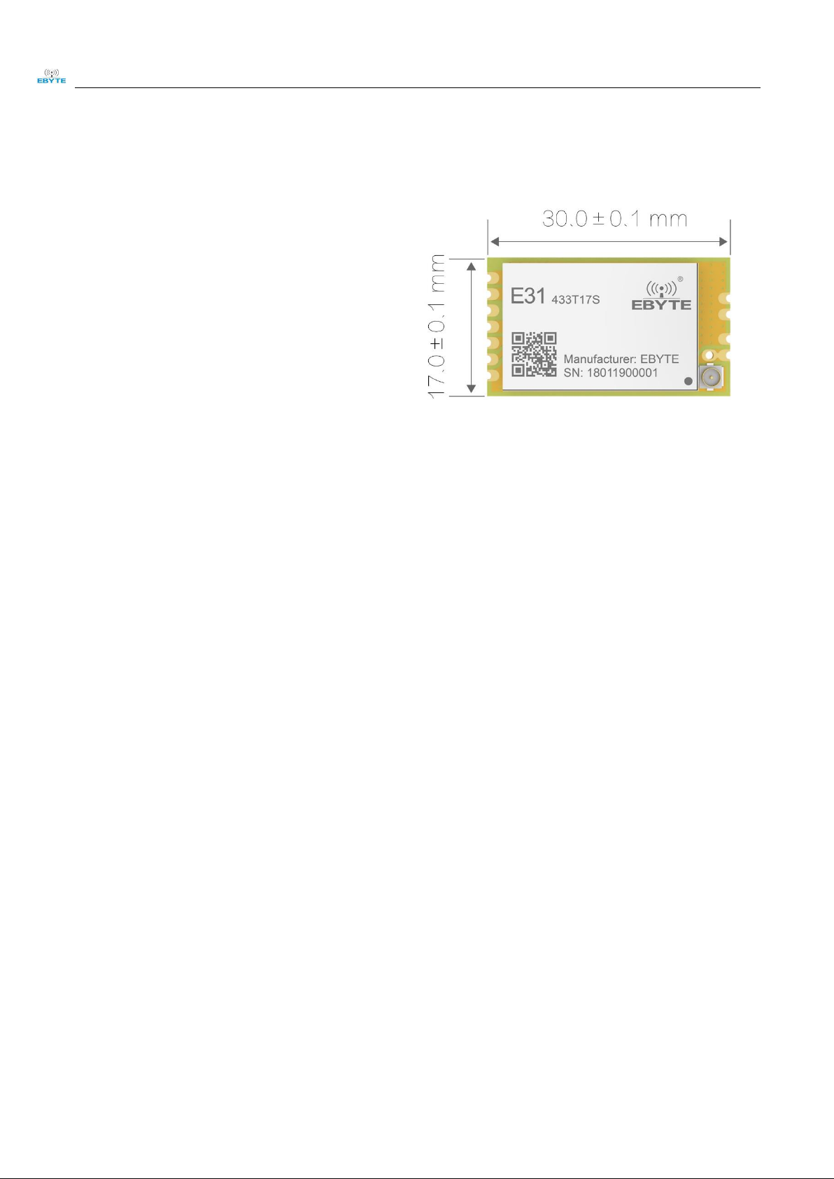
3. Size and pin definition
No.
Name
Direction
Function
1
M0
Input
(Weak pull-up)
Work with M 1 to decide 4 working modes of module (not susp ended, if
not used, could be grounded).
2
M1
Input
(weak pull-up)
Work with M 0 to decide 4 working modes of module (not susp ended, if
not used, could be grounded).
3
RXD
Input
TTL UART inputs, connects to external (MCU, PC) TXD output pin. Can
be configured as op en-drain or pull-up input.
4
TXD
Output
TTL UART output s, connects to external RXD (MCU, PC) input pin. Can
be configured as op en-drain or push-pull output
5
AUX
Output
To indicate module ’ s working status & wakes up the external M CU.
During the procedure of self-check initialization, the pin outp ut s low
level. Can be configured as push-p ull outp ut (suspending is allowed).
6
VCC
Input
Power sup p ly :2.1~ 5.5V DC
7
GND
Input
Ground
8
ANT
Output
Antenna interface (hf signal output pin)
9
GND
Input/Output
Antenna interface (high frequency signal reference ground)
10
GND
Input
Ground
Page 7
Chengdu Ebyte Electronic Technology Co.,Ltd. E31-433T17S User Manual
Copyright ©2012–2019,Chengdu Ebyte Electronic Technology Co.,Ltd. 6
11
GND
Input
Ground
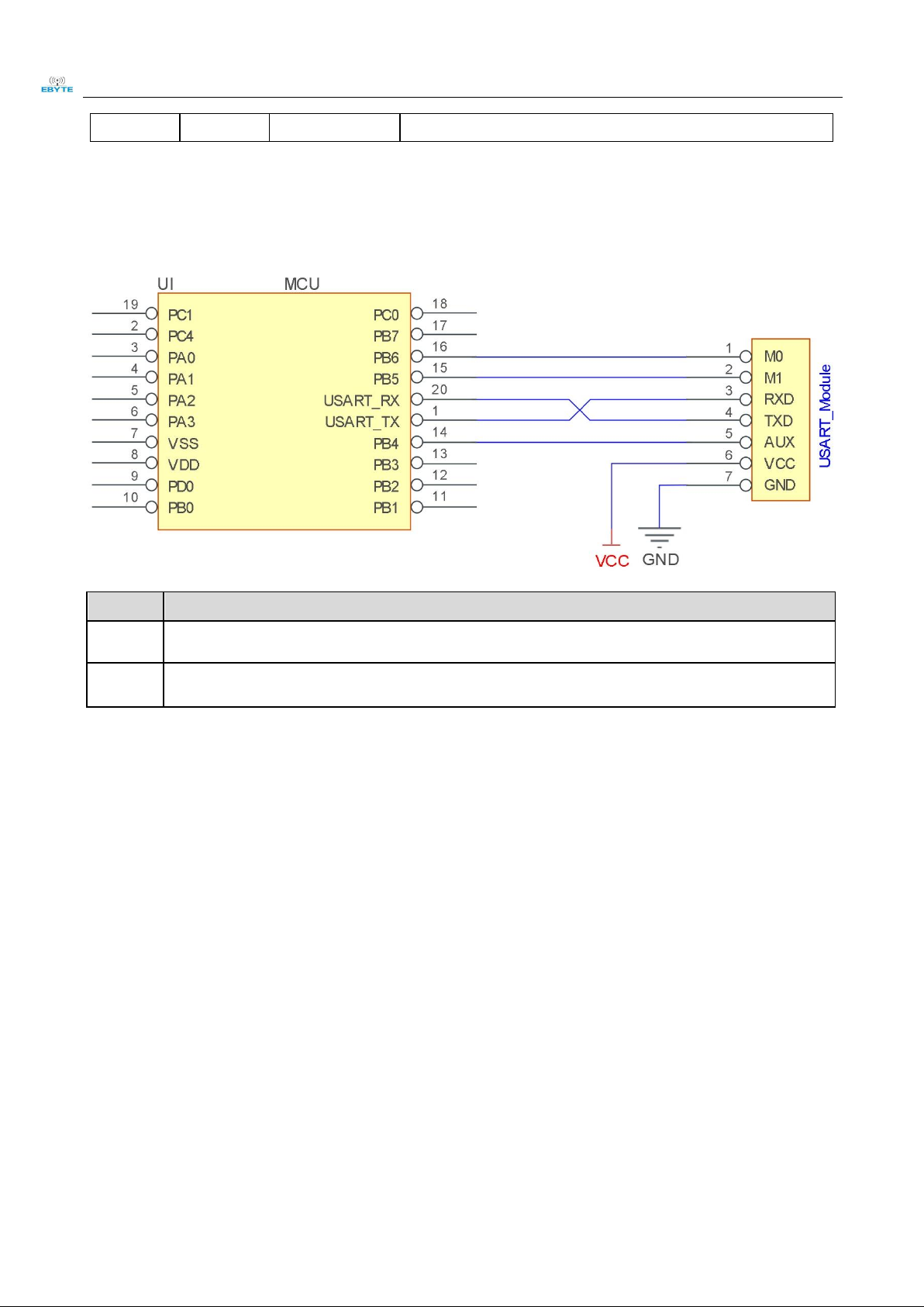
4. Connect to MCU
No.
Description(STM8L MCU)
1
The UART module is TTL level, pls connect to the MCU of TTL..
2
For some MCU works at 5VDC, it may need to add 4-10K pull-up resistor for the TXD & AUX pin.
Page 8

Chengdu Ebyte Electronic Technology Co.,Ltd. E31-433T17S User Manual
Copyright ©2012–2019,Chengdu Ebyte Electronic Technology Co.,Ltd. 7
5 Function description
5.1 Fixed transmission
5.2 Broadcasting transmission
5.3 Broadcasting address
For example: Set the address of module A as 0xFFFF or 0x0000, and the channel as 0x04;
Page 9

Chengdu Ebyte Electronic Technology Co.,Ltd. E31-433T17S User Manual
Copyright ©2012–2019,Chengdu Ebyte Electronic Technology Co.,Ltd. 8
When module A works as transmitter(same mode, transparent transmission), all the receivers with 0x04 channel can
receive the data, to realize the broadcast trans miss ion.
5.4 Monitor address
For example: Set the address of module A as 0xFFFF or 0x0000, and the channel as 0x04;
When module A is the receiver, it can receive the data sent from all modules under channel 0x04, the purpose of
monitor is realized.
5.5 Reset
When the module is powered, AUX outputs low level immediately, conducts hardware self-check and sets the
operating mode bas ed on user’s parameters. During the process, the AUX remains low level. After the process
completed, the AUX outputs high level and starts to work as per the operating mode combined by M1 and M0.
Therefore, us ers need to wait the AUX rising edge as the start of module’s normal work.
5.6 AUX description
AUX Pin can be used as indication for wireless send & receive buffer and self-check.
It can indicate whether there are data that are not sent yet via wireless way, or whether all wireless data has been sent
through UART, or whether the module is s till in the process of self-check initialization.
5.6.1 Indication of UART output
To wake up external MCU
5.6.2 Indication of wireless transmitting
Buffer (empty): the internal 512 bytes data in the buffer are written to the RFIC (Auto sub -packaging).
When AUX=1, the user can input data less than 512 bytes continuously without overflow. Buffer (not empty): when
Page 10

Chengdu Ebyte Electronic Technology Co.,Ltd. E31-433T17S User Manual
Copyright ©2012–2019,Chengdu Ebyte Electronic Technology Co.,Ltd. 9
AUX=0, the internal 512 bytes data in the buffer have not been written to the RFIC completely. If the us er starts to
trans mit data at this circumstance, it may caus e overtime when the module is waiting for the user data, or transmitting
wireless s ub package.
When AUX = 1, it does not mean that all the UART data of the module have been transmitted already, perhaps the
last packet of data is still in transmission.
5.6.3 Configuration procedure of module
Only happened when Reset and exit sleep mode
5.6.4 Notes for AUX
For function 1 & function 2 mentioned above, the priority should be given to the one with low level output, which
means if it meets each of any low level output condition, AUX outputs low level, if none of the low level con dition is
met, AUX outputs high level.
When AUX outputs low level, it means the module is bus y & cannot conduct operating mode checking. Within 1ms
since AUX outputs high level, the mode switch will be completed.
After switching to new operating mode, it will not work in the new mode immediately until AUX rising edge lasts for
2ms . If AUX s tays on the high level, the operating mode s witch can be effected immediately.
When the user switches to other operating modes from mode 3 (sleep mode) or it’s s till in reset proces s , the module
will reset us er parameters, during which AUX outputs low level.
Page 11

Chengdu Ebyte Electronic Technology Co.,Ltd. E31-433T17S User Manual
Copyright ©2012–2019,Chengdu Ebyte Electronic Technology Co.,Ltd. 10
6 Operating mode
There are four operating modes , which are set by M1 and M0, the details are as follows:
Mode(0-3)
M0
M1
Description
Remark
0 Normal mode
0
0
UART and wireless channel are op en, transp arent
transmission is on
The receiver must be M ode
0、1
1 WOR mode
1
0
UART and wireless channel are open;
The only difference with Mode 0: Before the data
packet transmitting, it will add wake-up code
automatically, in which the modules under mode 2 can
be wake up.
The receiver can be mode0, 1,
or 2
2 Power saving mode
0
1
UART receiving is closed, wireless channel is under
WOR mode, after the wireless data is received, the
wireless channel will be open and send the data out.
The transmitter must be mode
1. In this mode, the
transmission is unavailable.
3 sleep mode
1
1
The module enters sleep mode, but the parameters can
be configured.
See more details in working
parameters.
6.1 Mode switching
Users can combine M1 and M0 with high and low levels to determine the operating mode. Two GPIOs of the MCU
can be used to control mode switching; After changing M1 and M0: If the module is idle, after 1ms , it can start
working according to the new mode; If the serial port data of the module has not been trans mitted through the wireless,
the new working mode can be switched after the transmis s ion is completed; If the module receives the wireless data
and trans mits the data through the s erial port, it needs to finish trans miss io n before switching the new working mode;
Therefore, mode switching can only be valid when AUX output is 1, otherwise it will delay switching.
For example, in mode 0 or mode 1, users continuously inputs a large amount of data and simultaneous ly performs
mode s witching. At this time, the switching mode operation is invalid; the module will process all the user data befo re
performing the new mode detection; Therefore, the general recommendation is to detect the output state of the AUX
pin and switch after 2ms when the output is high.
When the module is switched from other modes to sleep mode, if the data has not been proces s ed yet; The module
will process thes e data (including receiving and sending) before entering sleep mode. This feature can be us ed for fast
sleep, which saves power; for example, the transmitter module works in mode 0, the user trans mits the serial port dat a
"12345", and then does not have to wait for the AUX pin to be idle (high level), and can directly switch to sleep mod e.
And the us er's main MCU immediately s leeps, the module will automatically trans mit the user data through the
wireless, and automatically enters sleep within 1ms; This saves MCU's working time and reduces power consumption.
Similarly, any mode switching can use this feature. After the module processes the current mode event, it will
automatically enter the new mode within 1ms; thus eliminating the need for the user to query AUX and achieve the
purpos e of fast switching; For example, switching from the transmit mode to the receive mode; the user MCU can
also enter sleep before the mode switch, and use the external interrupt function to acquire the AUX change, thereby
performing mode switching.
This operation mode is very flexible and efficient, and is des igned according to the user's MCU's operation
convenience, and can reduce the workload of the entire s ystem as much as possible, improve sys tem efficiency, and
reduce power consumption.
6.2 Normal mode(Mode 0)
Type
When M0 = 0,M1 = 0,the module works on Mode 0
Page 12

Chengdu Ebyte Electronic Technology Co.,Ltd. E31-433T17S User Manual
Copyright ©2012–2019,Chengdu Ebyte Electronic Technology Co.,Ltd. 11
Transmitting
The module receives the users’ data of serial port, and transmit 58 bytes wireless data p acket. When the
input data packet reaches 58 byt es, the module will start the wireless transmission, t hus users can continue
to input the transmitting data; When the input data packet is less than 58 bytes, the module will wait 3 bytes
time, if there’s no more data packet input, it means the data input finished, so the module will send all data
packet out via wireless; After the module receives the first data packet, the AUX outp uts low level; When
module put all data into RF chip and st art t he transmission, the AUX outputs high level; At this time, it
means the last data packet starts wireless transmission, users can continue to input 512 bytes data at most;
The data packet sent in M ode 0 can be only received by the module with M ode 0 and Mode 1.
Receiving
The module always open the wireless receiving function on, then it can receive the data p acket sent by
Mode 0 and Mode 1.
After receiving the data packet, the AUX of module outp ut s low level and after delaying 5ms, t he wireless
data will be transmitted via TXD pins of serial port. After all wireless data is transmitted via serial p ort, the
AUX outp uts high level.
6.3 WOR mode(Mode 1)
Type
When M0 = 1,M1 = 0,the module works on Mode 1
Transmitting
The condition of module starting data packet transmission and the AUX function equal to M ode 0. The
only difference is that module will add wake-up code automatically before each data packet. The length of
wake-up code depends on t he wake-up time set by users, the purp ose of wake-up code is to wake up the
module with M ode 2; So, t he transmitting data in M ode 1 can be received by the module with Mode 0, 1,
2.
Receiving
It equals to Mode 0.
6.4 Power saving mode(Mode 2)
Type
When M0 = 0,M1 = 1,the module works on Mode 2
Transmitting
The module is on sleep mode, serial p ort is close, so it cannot receive the serial p ort data of external M CU.
Thus, this module does not feature wireless transmitting function.
Receiving
In mode 2, the transmitter must be work in M ode 1; Monitoring the wake-up code at regular time, once a
valid wake-up code is received, the module continue to receive and wait for the entire valid data packet to
be received; Then AUX outp uts low level, after delaying 5ms, the serial p ort is open and the received
wireless data will be transmitted via TXD, after that, AUX outp uts high level; Wireless module continue
to enter “ Sleep-M onitor”working mode(polling); Set different wake-up time, the module has different
receiving response time (max 2s) and different average p ower consumption(min 30uA); Users need to
strike a balance between communication latency and average p ower consumption.
6.5 Sleep mode(Mode 3)
Type
When M0 = 1,M1 = 1,the module works on Mode 3
Transmitting
Transmitting the wireless data is unavailable.
Receiving
Receiving the wireless data is unavailable.
Configuration
Sleep mode can be used for module parameter setting. Use serial port 9600, 8N1 to set module working
parameters via specific command format.
Note
When entering other modes from the sleep mode, the module will reconfigure the parameters. During the
configuration p rocess, AUX keeps low level; after that, AUX outputs high level, so it is recommended that the
user detect the AUX rising edge.
Page 13

Chengdu Ebyte Electronic Technology Co.,Ltd. E31-433T17S User Manual
Copyright ©2012–2019,Chengdu Ebyte Electronic Technology Co.,Ltd. 12
7 Command format
In sleep mode (mode 3: M0 = 1, M1 = 1), the list of supported commands are as follows (only 9600, 8N1 format is
supported when):
No.
Command format
Description
1
C0+Working p arameters
The C0+5 by t e working parameter is sent in hexadecimal format, 6 bytes in all, and must
be sent continuously (power-down save)
2
C1+C1+C1
Three C1s are sent in hexadecimal format. The module returns the saved parameters and
must be sent continuously.
3
C2+Working p arameters
Send C2+5 byte working p arameters in hexadecimal format, 6 bytes in all, must be sent
continuously (power off without saving)
4
C3+C3+C3
Three C3s are sent in hexadecimal format. The module returns version information and
must be sent continuously.
5
C4+C4+C4
Three C4s are sent in hexadecimal format, and the module will generate a reset and must
be sent continuously.
7.1 Factory default parameter
Model
Factory default parameter value:C0 00 00 18 50 44
Module Model
Frequency
Address
Channel
Air data rate
Baud Rate
Serial p ort format
Transmitting
power
E31-433T17S
433MHz
0x0000
0x50
1.2kbps
9600
8N1
50mW
7.2 Working parameter reading
Instruction format
Detailed description
C1+C1+C1
In sleep mode (M0=1, M1=1), a command (HEX format) is issued to the module serial p ort : C1
C1 C1, the module will return the current configuration parameters, such as: C0 00 00 1A 17 44.
7.3 Version number reading
Instruction format
Detailed description
C3+C3+C3
In sleep mode (M 0=1, M 1=1), a command (HEX format) is issued to t he module serial port: C3
C3 C3, the module will return the current configuration parameters, such as: C3 32 xx yy ;the
second by te represents the frequency , if it’s 32,it is t he app licable frequency of 433M Hz, if it’s
38, it is the applicable frequency of 470MHz, if it’s 45, it is the app licable frequency of 868M Hz;
If it’s 44, it is the applicable frequency of 915M Hz; if it’s 46, it is t he app licable frequency of
170MHz; xx rep resents the version number, yy represents other features of module.
7.4 Reset instruction
Instruction format
Detailed description
Page 14

Chengdu Ebyte Electronic Technology Co.,Ltd. E31-433T17S User Manual
Copyright ©2012–2019,Chengdu Ebyte Electronic Technology Co.,Ltd. 13
C4+C4+C4
In sleep mode (M 0=1, M1=1), a command (HEX format) is issued to the module serial p ort::
C4 C4 C4, the module will generate a reset; during t he reset process, the module p erforms selftest, AUX output low level, After t he completion of reset, the AUX out p uts high and t he
module starts to work normally. At this t ime, Users can switch modes or initiate the next
instruction.
7.5 Parameter setting instruction
0
Name
Description
Note
0
HEAD
Fixed 0xC0 or 0xC2, which indicates that this frame data is a
control command
Must be 0xC0 or C2
C0:The set parameters will be saved after
power down.
C2:The set parameters will not be saved
after power down.。
1
ADDH
High byte of module address (default 00H)
00H-FFH
2
ADDL
Low byte of module address (default 00H)
00H-FFH
3
SPED
7
6
Serial parity bit
The serial port mode of the two
communication parties can be different
0
0
8N1(default)
0
1
8O1
1
0
8 E1
1
1
8N1(equals to 00)
5 4 3
TTL Serial port rate(bps)
The baud rate of both parties can be
different.
The serial port baud rate has nothing to
do with the wireless transmission
parameters, and does not affect the
wireless transmission and reception
characteristics.
0 0 0
Serial port baud rate 1200
0 0 1
Serial port baud rate 2400
0 1 0
Serial port baud rate 4800
0 1 1
Serial port baud rate 9600(default)
1 0 0
Serial port baud rate 19200
1 0 1
Serial port baud rate 38400
1 1 0
Serial port baud rate 57600
1 1 1
Serial port baud rate 115200
2 1 0
Wireless air data rate(bps)
The lower the air speed, the longer the
distance, the stronger the antiinterference performance and the longer
the transmission time.
The wireless transmission rates of both
communicating parties must be the same.
0 0 0
Air data rate 1.2k(default)
0 0 1
Air data rate 2.4k
0 1 0
Air data rate 4.8k
0 1 1
Air data rate 9.6k
1 0 0
Air data rate 19.2k
1 0 1
Air data rate 38.4k
1 1 0
Air data rate 50k
1 1 1
Air data rate 70k
4
CHAN
7 6 5
Keep and unused
Write 0.
Communication channel
00H-FFH,correspond 425 ~ 450.5MHz
4~0 correspond(425M + CHAN * 0.1M), default 50H
(433M)
5
OPTION
7
Fixed point send enable bit(similar to MODBUS)
When value is 1, the first 3 bytes of each
user data frame are used as the high and
0
Transparent transmission mode
Page 15

Chengdu Ebyte Electronic Technology Co.,Ltd. E31-433T17S User Manual
Copyright ©2012–2019,Chengdu Ebyte Electronic Technology Co.,Ltd. 14
1
Fixed point transmission mode
low addresses and channels. When
transmitting, the module changes its own
address and channel, and when it is
finished, it restores the original settings.
6
IO drive mode(default 1)
This bit is used to enable the internal
pull-up resistor of the module. Opendrain mode is more adaptable, and in
some cases an external pull-up resistor
may be required.
1
TXD、AUX push-pull output,RXD pull up input
0
TXD、AUX open-drain outp uts,RXD op en-drain
inputs
5 4 3
Wireless wakeup time
Both transmitter and receiver module
work in mode 0. The delay time is invalid
and can be any value.
The transmitter works in mode 1, and
will continue to transmit the call code for
the corresponding time.
The receiver works in mode 2, which
refers to the receiver's listening interval
(wireless wake-up) and can only receive
data from the module working in mode 1.
0 0 0
250ms(default)
0 0 1
500ms
0 1 0
750ms
0 1 1
1000ms
1 0 0
1250ms
1 0 1
1500ms
1 1 0
1750ms
1 1 1
2000ms
2
FEC switch
After the FEC is turned off, the actual
data transmission rate is increased, but
the anti-interference ability is weakened
and the distance is slightly closer. Please
choose according to the actual
application. Both sides of
the communication must be turned on or
off.
0
Turn off FEC
1
Open FEC(default)
1 0 Transmitting power (Approximate value)
The external power supply must provide
more than 200mA current output
capability. And ensure that the power
supply ripple is less than 100mV.
It is not recommended to use smaller
power transmission because of its low
power utilization efficiency.
0
0
17dBm(default)
0
1
14dBm
1
0
10dBm
1
1
7dBm
For example(The meaning of the No. 3 "SPED" byte):
The binary digit of the byte
7 6 5 4 3 2 1 0 Specific value(Users configure)
0 0 0 1 1 0 1
0
Meaning
Serial parity bit
8N1
Serial port baud rate 9600
Air data rate 2.4k
Corresponding hexadecimal 1 A
Page 16

Chengdu Ebyte Electronic Technology Co.,Ltd. E31-433T17S User Manual
Copyright ©2012–2019,Chengdu Ebyte Electronic Technology Co.,Ltd. 15
8 Hardware design
It is recommended to use a DC regulated power supply to supply power to the module. The power supply ripple
factor should be as small as possible, and the module needs to be reliably grounded.
Please pay attention to the correct connection of the po s itive and negative poles of the power supply. If the reverse
connection is made, the module may be permanently damaged.
Please check the power s upply to ensure that it’s within the recommended power supply, or the module will be
permanently damaged if it exceeds the maximu m value.
Please check the stability of the power supply, and the voltage cannot be fluctuated frequently;
When des igning the power supply circuit for the module, it is often recommended to reserve more than 30% of the
margin, which is beneficial for long-term stable operation of the whole machine
The module should be as far away as possible from the power supply, transformers, high -frequency wiring and other
parts with large electromagnetic interference;
High-frequency digital routing, high-frequency analog routing, and power routing must be avoided under the
module. If it is necessary to pass the module, it is assumed that the module is s oldered to the Top Layer, and the
copper is applied to the Top Layer of the module contact part(Copper is well grounded), and must be clos e to the
digital part of the module and routed in the Bottom Layer;
As suming that the module is soldered or placed in the Top Layer, it is also wrong to randomly route the Bottom
Layer or other layers, which will affect the spurs and receiving sens itivity of the module in varying degrees;
As sume that there are devices with large electromagnetic interference around the module that will greatly affec t the
performance of the module. It is recommended to keep away from the module according to the strength of the
interference. If neces sary, appropriate isolation and shielding can be done.
As sume that there are traces with large electromagnetic interference around the module (high -frequency digital,
high-frequency analog, power trace), which will greatly affect the performance of the module. It is recommended to
stay away from the module according to the strength of the interference. If possible, us ers can do some proper
isolation and shielding;
If the communication line uses 5V level, it must be connected in series with 1k-5.1k resistor (not recommended,
there is still risk of damage);
Try to s tay away from some phys ical layers which is 2.4GHz TTL protocol, for example: USB3.0;
The antenna installation structure has a great influence on the performance of the module. Make sure that the
antenna is exposed, preferably vertically. When the module is installed inside the casing, a good antenna exten sion
cable can be used to extend the antenna to the outside of the casing;
The antenna can not be installed inside the metal cas e, which will greatly reduce the transmission distance.
Page 17

Chengdu Ebyte Electronic Technology Co.,Ltd. E31-433T17S User Manual
Copyright ©2012–2019,Chengdu Ebyte Electronic Technology Co.,Ltd. 16
9 FAQ
9.1 Transmission distance is not ideal
When there is a linear communication obstacle, the communication distance will be correspondingly reduced;
Temperature, humidity, and co-channel interference will lead to an increas e in communication packet loss rate;
The ground absorbs and reflects radio waves, so the test results close to the ground are poor.
Seawater has a strong ability to absorb radio wav es , so the seas ide test results are poor.
There are metal objects near the antenna, or placed in the metal s hell, the signal attenuation will be very ser ious;
Power register setting error, air data rate s etting is too high (the higher the air data rate, th e clos er the distance);
The low voltage of the power supply is lower than the recommended value at room temperature, and the lower the
voltage, the smaller the power;
The matching degree of antenna and module is poor, or the quality of the antenna itself.
9.2 Module is easy to damage
Please check the power s upply to ensure that it’s within the recommended power supply, or the module will be
permanently damaged if it exceeds the maximu m value.
Check the stability of the power supply and the voltage cannot be fluctuated frequently.
Please ensure that the installation process is anti-static, and the high-frequency components are electrostatically
sens itive.
Please ensure that the humidity during installation and use is not too high becaus e some components are humidity
sens itive devices.
If there is no s pecial demand, it is not recommended to use it at too high or too low temperature.
9.3 Bit error rate is too high
There are co-channel signal interference nearby, away from interference s ources or modify frequency and channel
to avoid interference;
The undesirable power supply may also caus e mess y code, and ensure the reliability of the power supply.
The quality of extens ion line and feeder are poor or too long, which also cause high bit error rate;
10 Welding operation guidance
10.1 Reflow temperature
Profile Feature
Curve feature
Sn-Pb Assembly
Pb-Free Assembly
Solder Paste
Solder paste
Sn63/Pb37
Sn96.5/Ag3/Cu0.5
Preheat Temperature min (Tsmin)
Min. preheating temperature
100℃
150℃
Preheat temperature max (Tsmax)
Max. preheating temperature
150℃
200℃
Preheat Time (Tsmin to Tsmax)(ts)
Preheating time
60-120 sec
60-120 sec
Page 18

Chengdu Ebyte Electronic Technology Co.,Ltd. E31-433T17S User Manual
Copyright ©2012–2019,Chengdu Ebyte Electronic Technology Co.,Ltd. 17
Average ramp-up rate(Tsmax to Tp)
Average rising rate
3℃/second max
3℃/second max
Liquidous Temperature (TL)
Liquidus temperature
183℃
217℃
Time(tL)Maintained Above(TL)
The time above the liquidus
60-90 sec
30-90 sec
Peak temperature(Tp)
Peak temperature
220-235℃
230-250℃
Average ramp-down rate(Tp to
Tsmax)
Average decline rate
6℃/second max
6℃/second max
Time 25℃ to peak temperature
Time from 25℃ to peak
temperature
6 minutes max
8 minutes max
10.2 Reflow profile
11 E31 Series
Product
Model
Chip
Frequenc
y Hz
Transmitting
power dBm
Test distance
km
Air data rate
bps
Packin
g
Size
mm
Antenna
E31-230T33D
AX5243
230M
33
8
1.2k~70k
DIP
37 * 60
SMA-K
E31-230T27D
AX5243
230M
27
5
1.2k~70k
DIP
24 * 43
SMA-K
E31-230T17D
AX5243
230M
17
2
1.2k~70k
DIP
21 * 36
SMA-K
E31-433T33D
AX5243
433M
33
8
1.2k~70k
DIP
37 * 60
SMA-K
E31-433T30D
AX5243
433M
30
6
1.2k~70k
DIP
24 * 43
SMA-K
Page 19

Chengdu Ebyte Electronic Technology Co.,Ltd. E31-433T17S User Manual
Copyright ©2012–2019,Chengdu Ebyte Electronic Technology Co.,Ltd. 18
E31-433T27D
AX5243
433M
27
4
1.2k~70k
DIP
24 * 43
SMA-K
E31-433T17D
AX5243
433M
17
2.1
1.2k~70k
DIP
21 * 36
SMA-K
E31-433T17S
AX5243
433M
17
2
1.2k~70k
SMD
17 * 30
Stamp hole+IPEX
E31-433T17S3
AX5243
433M
17
2
1.2k~70k
SMD
16 * 26
Stamp hole+IPEX
12 Antenna Instruction
12.1 Antenna recommendation
The antenna plays an important role in the communication proces s . The inferior antenna often has a great impact on
the communication system. Therefore, we recommend our antennas , which have excellent performance and reas onable
price, to support our wireless modules.
Product Model
Type
Frequenc
y Hz
Interfac
e
Gain
dBi
Height
Cable
Features
TX433-NP-4310
Flexible PCB
antenna
433M
SMA-J
2
43.8*9.5mm
-
Built-in flexible FPC soft antenna
TX433-JW-5
Rubber antenna
433M
SMA-J 2 50mm - Flexible, omni antenna
TX433-JWG-7
Rubber antenna
433M
SMA-J
2.5
75mm - Flexible, omni antenna
TX433-JK-20
Rubber antenna
433M
SMA-J 3 210mm
-
Flexible, omni antenna
TX433-JK-11
Rubber antenna
433M
SMA-J
2.5
110mm
-
Flexible, omni antenna
TX433-XP-200
Sucker antenna
433M
SMA-J 4 19cm
200cm
Sucker antenna, high gain
TX433-XP-100
Sucker antenna
433M
SMA-J
3.5
18.5cm
100cm
Sucker antenna, high gain
TX433-XPH-300
Sucker antenna
433M
SMA-J 6 96.5cm
300cm
Vehicle sucker antenna, super high
gain
TX433-JZG-6
Rubber antenna
433M
SMA-J
2.5
52mm
-
Ultra short straight, omni antenna
TX433-JZ-5
Rubber antenna
433M
SMA-J 2 52mm
-
Ultra short straight, omni antenna
Page 20

Chengdu Ebyte Electronic Technology Co.,Ltd. E31-433T17S User Manual
Copyright ©2012–2019,Chengdu Ebyte Electronic Technology Co.,Ltd. 19
13 Batch packaging method
Page 21

Chengdu Ebyte Electronic Technology Co.,Ltd. E31-433T17S User Manual
Copyright ©2012–2019,Chengdu Ebyte Electronic Technology Co.,Ltd. 20
Revise history
Version
Date
Description
Iss ued by
1.00
2017-11-17
Initial version
huaa
1.20
2018-01-29
Content updated
huaa
1.30
2018-10-17
New model added
huaa
About us
Technical sup p ort : supp ort@cdebyte.com
Documents and RF Setting download link: www.ebyt e.com
Thank you for using Ebyte products! Please contact us with any questions or suggestions: info@cdebyte.com
-----------------------------------------------------------------------------------------------------------Fax: 028-64146160 ext. 821
Web: www.ebyte.com
Address: Innovation Center D347, 4# XI-XIN Road,Chengdu, Sichuan, China
 Loading...