

Page 1

E30-490T20S User Manual
SI4438 490MHz 100mW SMD Wireless Module
Page 2

Chengdu Ebyte Electronic Technology Co,;Ltd E30-490T20S user manual
Copyright ©2012–2019,Chengdu Ebyte Electronic Technology Co,;Ltd 1
CONTENT
1OVERVIEW .......................................................................................................................................3
1.1 INTRODUCT ION ................................................................................................................................................................................3
1.2 FEAT URES.........................................................................................................................................................................................3
2 SPECIFICATION AND PARAMETER .........................................................................................4
2.1 LIMIT PARAMETER ..........................................................................................................................................................................4
2.2 OPERATING PARAMETER ................................................................................................................................................................4
3 SIZE AND PIN DEFINITION. ........................................................................................................5
4 CONNECT TO MCU .......................................................................................................................6
5 FUNCTION DESCRIPTION ..........................................................................................................7
5.1 FIXED TRANSMISSION.....................................................................................................................................................................7
5.2 BROADCASTING T RANSMISSION ...................................................................................................................................................7
5.6.1 Indication of UART output
...................................................................................................................................................8
5.6.2 Indication of wireless transmitting
.....................................................................................................................................8
5.6.3 Configuration procedure of module
....................................................................................................................................9
5.6.4 Notes for AUX
.........................................................................................................................................................................9
6 OPERATING MODE .................................................................................................................... 10
6.1 MODE SWITCH .............................................................................................................................................................................. 10
6.2 NORMAL MODE (MODE 0) ........................................................................................................................................................... 11
6.3 WAKE-UP MODE (MODE 1).......................................................................................................................................................... 11
6.4 POWER-SAVING MODE (MODE 2)................................................................................................................................................ 11
6.5 SLEEP MODE (MODE 3) ................................................................................................................................................................ 12
7 COMMAND FORMAT ................................................................................................................. 12
7.1 DEFAULT PARAMETERS................................................................................................................................................................ 13
7.2 READING OP ERATING PARAMETERS........................................................................................................................................... 13
7.3 READING VERSION NUMBER ....................................................................................................................................................... 13
7.4 RESET COMMAND......................................................................................................................................................................... 13
7.5 PARAMETER SETTING COMMAND .............................................................................................................................................. 13
8. HARDWARE DESIGN ................................................................................................................ 15
9 FAQ ................................................................................................................................................. 16
Page 3

Chengdu Ebyte Electronic Technology Co,;Ltd E30-490T20S user manual
Copyright ©2012–2019,Chengdu Ebyte Electronic Technology Co,;Ltd 2
9.1 COMMUNICATION RANGE IS TOO SHORT ................................................................................................................................... 16
9.2 MODULE IS EASY TO DAMAGE.................................................................................................................................................... 17
9.3 BER(BIT ERROR RAT E) IS HIGH................................................................................................................................................. 17
10 PRODUCTION GUIDANCE ..................................................................................................... 17
10.1 REFLOW SOLDERING TEMPERATURE ....................................................................................................................................... 17
10.2 REFLOW SOLDERING CURVE..................................................................................................................................................... 18
11.E30 SERIES .................................................................................................................................. 18
12 ANTENNA RECOMMENDATION ........................................................................................... 19
13. PACKAGE FOR BATCH ORDER ........................................................................................... 19
REVISION HISTORY...................................................................................................................... 20
ABOUT US ........................................................................................................................................ 20
Page 4

Chengdu Ebyte Electronic Technology Co,;Ltd E30-490T20S user manual
Copyright ©2012–2019,Chengdu Ebyte Electronic Technology Co,;Ltd 3
1.Overview
1.1 introduction
E30-490T20S is based on originally imported SI4438 from
Silicon Labs, with transparent transmission available, TTL level
output with air wake-up function, WOR (ultra-low power
consumption). They feature half duplex and SMD interface. 490M
frequency, long wave length and strong ability of penetration and
diffraction. They are applicable in the indus trial and living
environment like a plant or indoors.
The module features FEC (Forward Error Correction )
algorithm, which ensure its high coding efficiency & good correction
performance. In the cas e of sudden interference, it can correct the interfered data packets proactively, so that the re liabilit y
& transmis s ion range are improved correspondingly. But without FEC, thos e data packets can only be dropped.
E30-490T20S strictly follows design standards of FCC, CE, CCC and meets various RF certification requirements
for exporting.
1.2 Features
Communication distance tested is up to 2.5km
Maximum transmission power of 100mW, software multi-level adjustable;
Support the global license-free ISM 490MHz band;
Support air date rate of 1kbps ~25kbps ;
Low power consumption for battery supplied applications;
Support 2.3V~5.2V power supply, power supply over 2.3V can guarantee the best performance ;
Industrial grade s tandard design, support -40 ~ 85 °C for working over a long time;
Support IPEX/External/Spring,us ers can choose to use according to their own needs.
1.3 Application
Home s ecurity alarm and remote keyless entry;
Smart home and industrial sensors;
Wireless alarm security system;
Building automation solutions ;
Wireless industrial-grade remote control;
Health care products ;
Advanced Meter Reading Architecture(AMI);
Automotive industry applications .
Page 5

Chengdu Ebyte Electronic Technology Co,;Ltd E30-490T20S user manual
Copyright ©2012–2019,Chengdu Ebyte Electronic Technology Co,;Ltd 4
2 Specification and parameter
2.1 Limit parameter
Main parameter
Performance
Notes
Min.
Max.
Power sup p ly (V)
0
5.2
Voltage over 5.2V will cause p ermanent
damage to module
Blocking p ower(dBm)
-
10
Chances of burn is slim when modules
are used in short distance
Operating temperature(℃)
-40
85
2.2 Operating parameter
Main parameter
Performance
Notes
Min
Typ.
Max.
Operating voltage(V)
2.3
3.3
5.2
≥3.3V ensures outp ut power
Communication level(V)
3.3
For 5V TTL, it may be at risk of
burning down
Operating temperature(℃)
-40 - 85
Industrial design
Operating frequency(M Hz )
470 - 500.5
Support ISM band
Power
consumption
Transmitting current [mA]
89 Instant power consumption
Receiving current [mA]
16
Turn-off current [μA]
4
Software is shut down
Max Tx power(dBm)
19.4
20.0
20.5
Receiving sensitivity(dBm)
-120
-121
-122
Air data rate is 1.0kbps
Air data rate(bps)
1k
5k
25k
Controlled via user’s programming
Main parameter
Description
Notes
Distance for reference
2500m
Test condition:clear and open area, antenna gain: 5dBi,
antenna height: 2.5m,air data rate: 1.0kbps
TX length
58 Byte
Maximum capacity of single package, automatic subpacking after exceeding.
Buffer
512 Byte
Modulation
GFSK
Communication interface
TTL
@3.3V
Package
SMD
Connector
2.00mm
Page 6
Chengdu Ebyte Electronic Technology Co,;Ltd E30-490T20S user manual
Copyright ©2012–2019,Chengdu Ebyte Electronic Technology Co,;Ltd 5
Size
17 * 30 mm
Antenna
IPEX/External/Spring
50 ohm impedance
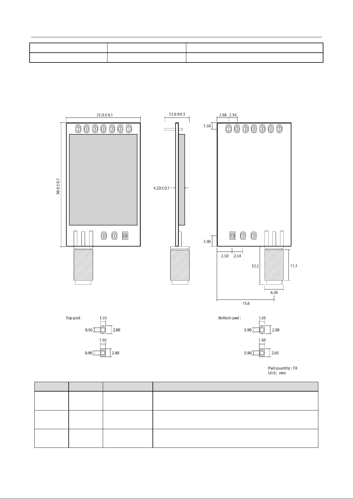
3 Size and pin definition.
No.
Name
Direction
Function
1
M0
Input
(Weak pull-up)
Work with M 1 to decide 4 working modes of module (not susp ended, if
not used, could be grounded).
2
M1
Input
(weak pull-up)
Work with M 0 to decide 4 working modes of module (not susp ended, if
not used, could be grounded).
3
RXD
Input
TTL UART input s, connects to external (M CU, PC) TXD output pin. Can
be configured as op en-drain or pull-up input .
Page 7
Chengdu Ebyte Electronic Technology Co,;Ltd E30-490T20S user manual
Copyright ©2012–2019,Chengdu Ebyte Electronic Technology Co,;Ltd 6
4
TXD
Output
TTL UART output s, connects to external RXD (MCU, PC) inp ut pin. Can
be configured as op en-drain or push-pull out p ut
5
AUX
Output
To indicate module ’ s working status & wakes up the external M CU.
During the procedure of self-check initialization, the pin outp ut s low
level. Can be configured as push-p ull outp ut (suspending is allowed).
6
VCC
Input
Power sup p ly :2.3~ 5.5V DC
7
GND
Input
Ground
8
ANT
Input
Antenna interface (high frequency signal outp ut )
9
Fixed orifice
Fixed orifice
10
Fixed orifice
Fixed orifice
11
Fixed orifice
Fixed orifice
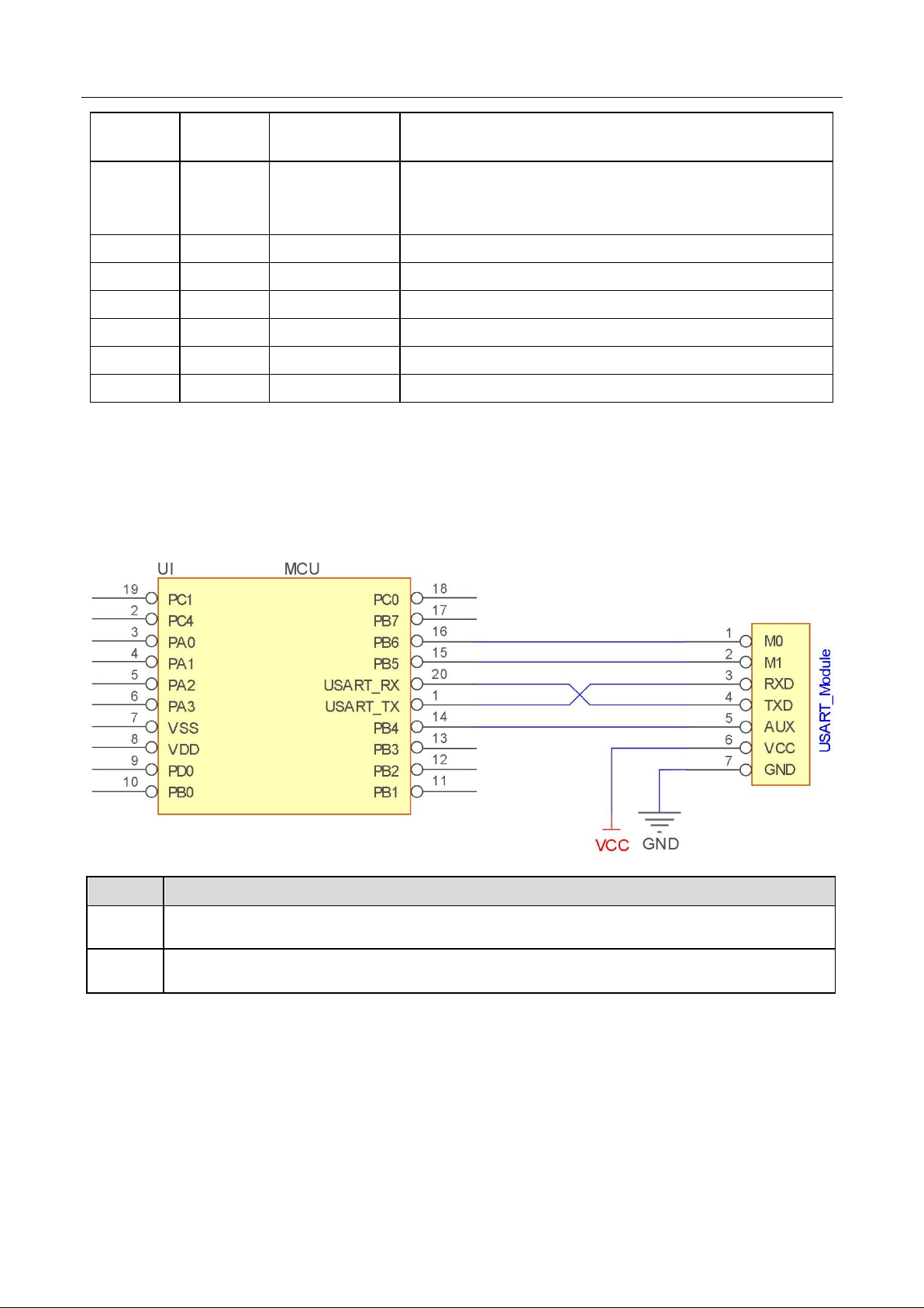
4 Connect to MCU
No.
Description(STM8L MCU)
1
The UART module is TTL level.
2
For some MCU works at 5VDC, it may need to add 4-10K pull-up resistor for the TXD & AUX pin.
Page 8

Chengdu Ebyte Electronic Technology Co,;Ltd E30-490T20S user manual
Copyright ©2012–2019,Chengdu Ebyte Electronic Technology Co,;Ltd 7
5 Function description
5.1 Fixed transmission
5.2 Broadcasting transmission
5.3 Broadcasting address
For example: Set the addres s of module A as 0xFFFF or 0x0000, and the channel as 0x04;
Page 9

Chengdu Ebyte Electronic Technology Co,;Ltd E30-490T20S user manual
Copyright ©2012–2019,Chengdu Ebyte Electronic Technology Co,;Ltd 8
When module is the transmitter (transparent transmission), all modules under channel 0x04 will receive the data, the
purpos e of broadcast is realized.
5.4 Monitor address
For example: Set the addres s of module A as 0xFFFF or 0x0000, and the channel as 0x04;
When module A is the receiver, it can receive the data s ent from all modules under channel 0x04, the purpose of
monitor is realized.
5.5 Reset
When the module is powered, AUX outputs low level immediately, conducts hard ware self-check and sets the
operating mode bas ed on user’s parameters. During the process, the AUX remains low level. After the process
completed, the AUX outputs high level and starts to work as per the operating mode combined by M1 and M0.
Therefore, us ers need to wait the AUX rising edge as the start of module’s normal work.
5.6 AUX description
AUX Pin can be used as indication for wireless send & receive buffer and self-check.
It can indicate whether there are data that are not sent yet via wireless way, or whether all wireless data has been s ent
through UART, or whether the module is s till in the process of self-check initialization.
5.6.1 Indication of UART output
MCU. To wake up external MCU
5.6.2 Indication of wireless transmitting
Buffer (empty): the internal 512 bytes data in the buffer are written to the RFIC (Auto sub -packaging).
When AUX=1, the user can input data less than 512 bytes continuous ly without overflow. Buffer (not empty): when
Page 10

Chengdu Ebyte Electronic Technology Co,;Ltd E30-490T20S user manual
Copyright ©2012–2019,Chengdu Ebyte Electronic Technology Co,;Ltd 9
AUX=0, the internal 512 bytes data in the buffer have not been written to the RFIC completely. If the us er starts to
trans mit data at this circumstance, it may caus e overtime when the module is waiting for the user data, or transmitting
wireless sub package.
When AUX = 1, it does not mean that all the UART data of the module have been transmitted already, perhaps the
last packet of data is still in transmission.
5.6.3 Configuration procedure of module
Only happened when power-on resetting or exiting s leep mode
5.6.4 Notes for AUX
No.
Description
1
For function 1 & function 2 mentioned above, t he priority should be given to the one with low level outp ut , which means if it
meets each of any low level outp ut condition, AUX outp uts low level, if none of the low level condition is met, AUX output s high
level.
2
When AUX outputs low level, it means the module is busy & cannot conduct operating mode checking. Within 1ms since AUX
outp uts high level, the mode switch will be completed.
Page 11

Chengdu Ebyte Electronic Technology Co,;Ltd E30-490T20S user manual
Copyright ©2012–2019,Chengdu Ebyte Electronic Technology Co,;Ltd 10
3
After switching to new op erating mode, it will not work in t he new mode immediately until AUX rising edge lasts for 2ms . If
AUX stays on the high level, the operating mode switch can be affected immediately.
4
When the user switches to other operating modes from mode 3 (sleep mode) or it’s still in reset process, the module will reset user
parameters, during which AUX outputs low level.
6 Operating mode
There are four operating modes , which are set by M1 and M0, the details are as follows:
Mode(0-3)
M0
M1
Mode introduction
Remark
0 Normal
0
0
UART and wireless channel are op en, t ransp arent
transmission is on
The receiver must work in
mode 0 or mode 1
1 Wake up
1
0
UART and wireless channel are open, the only difference
with mode 0 is that before transmitting data, increasing
the wake up code automatically, so that it can awake the
receiver under mode 2.
The receiver could be 0,1 or
2
2 Power
saving 0 1
UART close, wireless is under air-awaken mode, after
receiving data, UART open and send data.
transmitter must be mode 1,
unable to transmit in this
mode.
3 Sleep
1
1
sleep mode, receiving p arameter setting command is
available.
more details on parameter
specification.
6.1 Mode switch
The user can decide the operating mode by the combination of M1 and M0. The two GPIO of MCU can be used to
switch mode. After modifying M1 or M0, it will start to work in new mode 1ms later if the module is free. If there are
any serial data that are yet to finish wireless trans mitting, it will start to work in new mode after the UART transmitting
finished. After the module receives the wireless data & transmits the data through serial port, it will start to work in
new mode after the transmitting finished. Therefore, the mode-switch is only valid when AUX outputs 1, otherwise
it will delay.
For example, in mode 0 or mode 1, if the user inputs mas s ive data cons ecutively and switches operating mode at the
same time, the mode-switch operation is invalid. New mode checking can only be started after all the us er’s data
process completed. It is recommended to check AUX pin out status and wait 2ms after AUX outputs high level before
switching the mode.
If the module switches from other modes to stand-by mode, it will work in s tand -by mode only after all the remained
data process completed. The feature can be used to save power cons umption. For example, when the transmitter works
in mode 0, after the external MCU transmits data “12345”, it can switch to sleep mode immediately without waiting
the rising edge of the AUX pin, also the user’s main MCU will go dormancy immediately. Then the module will
trans mit all the data through wireless trans mission & go dormancy 1ms later automatically, which reduces MCU
working time & save power.
Likewise, this feature can be us ed in any mode-switch. The module will start to work in new mode within 1ms after
completing present mode task, which enables the us er to omit the procedure of AUX inquiry and switch mode swiftly.
For example, when switching from transmitting mode to receiving mode, the us er MCU can go dormancy before
Page 12

Chengdu Ebyte Electronic Technology Co,;Ltd E30-490T20S user manual
Copyright ©2012–2019,Chengdu Ebyte Electronic Technology Co,;Ltd 11
mode-switch, using external interrupt function to get AUX change so that the mode -switch can be realized.
This operation is very flexible and efficient. It is totally des igned on the bas is of the user MCU’s convenience, at the
same time the work load and power consumption of the whole system have been reduced and the efficiency of whole
system is largely improved.
6.2 Normal mode (mode 0)
When M1 = 0 & M0 = 0, module works in mode 0
Transm
itting
The module can receive the user data via serial p ort, and transmit wireless data package of 58 bytes. When the data
inputted by user is up to 58 byte, the module will start wireless transmission. During which the user can inp ut data
continuously for transmission.
When the required transmission bytes are less than 58 bytes, the module will wait 3-by t e time and treat it as data
termination unless continuous data inputted by user. T hen the module will transmit all the data through wireless channel.
When the module receives the first data packet from user, the AUX outp uts low level.
After all the data are transmitt ed into RF chip and transmission start , AUX outputs high level.
At this time, it means t hat the last wireless data package transmission is started, which enables the user to input another
512 bytes continuously. The data package transmitted from the module working in mode 0 can only be received by the
module working in mode 0 or 1.
Receiv
ing
The wireless receiving function of the module is on, t he data packet transmitted from t he module working in mode 0 &
mode 1 can be received.
After the data packet is received, the AUX outputs low level, 5ms later the module starts to transmit wireless data through
serial port TXD pin.
After all the wireless data have been transmitted via serial p ort, the AUX outp uts high level.
6.3 Wake-up mode (mode 1)
When M1 = 0 & M0 = 1, module works in mode 1
Transmitting
The condition of data packet transmission & AUX function is the same as mode 0. The only difference is that
the module will add preamble code before each data packet automatically. The preamble code lengt h depends
on the wake-up time set in the user parameters. The purp ose of the preamble code is waking up the receiving
module works in mode 2. Therefore, the data package transmitted from mode 1 can be received by mode 0,
mode1 and mode 2.
Receiving
The same as that in mode 0.
6.4 Power-saving mode (mode 2)
When M1 = 1 & M0 = 0, module works in mode 2
Transmitting
UART is closed, the module cannot receive any serial p ort data from outside M CU.
Hence the function of wireless transmission is not available for the module working in this mode.
Page 13

Chengdu Ebyte Electronic Technology Co,;Ltd E30-490T20S user manual
Copyright ©2012–2019,Chengdu Ebyte Electronic Technology Co,;Ltd 12
Receiving
In mode 2, it is required the data transmitter works in mode 1.
The wireless module monitors the preamble code at regular t ime.
Once it gets the preamble code, it will remain as receiving status and waiting for the completion of receiving
the entire valid data package.
Then the AUX outputs low level, 5ms later the serial port is open to transmit received wireless data through
TXD. Finally, AUX outputs high level after process completed.
The wireless module stays in “p ower-saving – monitoring” working status (polling).
By setting different wake-up time, the module will have different receiving response delay (2s in maximum)
and average power consumpt ion (30uA in minimum).
The user needs to achieve a balance between communication delay time & average p ower consumption.
6.5 Sleep mode (mode 3)
When M1=1, M0=1, module works in mode 3
Transmitting
N/A
Receiving
N/A
Parameter
setting
This mode can be used for parameter sett ing. It uses serial port 9600 & 8N1 t o set module working parameters
through specific instruction format. (pls refer to parameters sett ing for details)
Notes
When the mode changes from stand-by mode to others, the module will reset its parameters, during which the AUX
keeps low level and then outputs high level after reset completed. It is recommended to check the AUX rising edge
for user.
7 Command format
In sleep mode(Mode 3:M1=1, M0=1), it s upports below instructions on list.
(Only support 9600 and 8N1 format when setting)
No.
Instruction
format
Illustration
1
C0+working
parameters
C0 + 5 bytes working p arameters are sent in hexadecimal format. 6 by t es in tot al and
must be sent in succession, ( Save t he parameters when power-down ).
2
C1+C1+C1
( Save the parameters when power-down )
3
C2+working
parameters
Three C1 are sent in hexadecimal format. The module returns the saved parameters and
must be sent in succession.
4
C3+C3+C3
C2 + 5 bytes working p arameters are sent in hexadecimal format. 6 by t es in tot al and
must be sent in succession. ( Do not save the p arameters when power-down )
5
C4+C4+C4
Three C3 are sent in hexadecimal format. The module returns the version information
and they must be sent in succession.
Page 14

Chengdu Ebyte Electronic Technology Co,;Ltd E30-490T20S user manual
Copyright ©2012–2019,Chengdu Ebyte Electronic Technology Co,;Ltd 13
7.1 Default parameters
Type
Default parameter values:C0 00 00 18 DC 44
Model
Frequency
Address
Channel
Air data rate
Baud rate
Parity
Transmittin
g power
E30-490T20S
490MHz
0x0000
0x96
1kbps
9600
8N1
100mW
7.2 Reading operating parameters
Instruction format
Description
C1+C1+C1
In sleep mode(M0=1,M 1=1),
User gives the module instruction (HEX format): C1 C1 C1,
Module returns the p resent configuration p arameters.
For example, C0 00 00 1A 17 44.
7.3 Reading version number
Instruction format
Description
C3+C3+C3
In sleep mode(M0=1,M 1=1),User gives the module instruction (HEX format): C3 C3 C3,Module
returns its present version number, for example C3 32 xx yy. t he second by tes means frequency. 32
here means the frequency is 433MHZ, 38 means frequency is 470MHz , 45 means frequency is;
868MHz, 44 means the frequency is 915 M Hz , 46 means the frequency is 170M Hz; xx is the version
number and yy refers t o the other module features.
7.4 Reset command
Instruction format
Description
C4+C4+C4
In sleep mode(M0=1,M 1=1),
User gives the module instruction (HEX format): C4 C4 C4, the module resets for one time. During the
reset process, the module will conduct self-check, AUX out p uts low level. After reset completing, t he
AUX outp uts high level, t hen the module st arts to work regularly which the working mode can be
switched or be given another instruction.
7.5 Parameter setting command
No.
Item
Description
Remark
0
HEAD
Fix 0xC0 or 0xC2, it means this frame data is control command
Must be 0xC0 or 0xC2
C0: Save the p arameters when power-down
C2: Do not save the parameters when power-down
1
ADDH
High address byte of module
(the default 00H)
00H-FFH
Page 15

Chengdu Ebyte Electronic Technology Co,;Ltd E30-490T20S user manual
Copyright ©2012–2019,Chengdu Ebyte Electronic Technology Co,;Ltd 14
2
ADDL
Low address byte of module
(the default 00H)
00H-FFH
3
SPED
7
6
UART parity bit
UART mode can be different between
communication parties
0
0
8N1 (default)
0
1
8O1
1
0
8 E1
1
1
8N1 (equal to 00)
5 4 3
TTL UART baud rate(bps)
UART baud rate can be different between
communication parties
The UART baud rate has nothing to do with
wireless transmission parameters & won’t
affect the wireless transmit / receive features.
0 0 0
1200
0 0 1
2400
0 1 0
4800
0 1 1
9600 (default)
1 0 0
19200
1 0 1
38400
1 1 0
57600
1 1 1
115200
2 1 0
Air data rate(bp s)
The lower the air data rate, the longer the
transmitting dist ance, bett er anti-interference
performance and longer transmitting time
The air data rate must keep the same for both
communication parties.
0 0 0
1k
0 0 1
2k
0 1 0
5k (default)
0 1 1
8k
1 0 0
10k
1 0 1
15k
1 1 0
20k
1 1 1
25k
4
CHAN
7 6 5
reserved
Write 0
Communication channel
00H-FFH, correspond to 475 ~ 500.5M Hz
4 ~ 0, channel (475M + CHAN * 0.1M) , default 96H (490M Hz)
5
OPTIO
N
7
Fixed t ransmission enabling bit(similar to M ODBUS)
In fixed transmission mode, the first three
bytes of each user's data frame can be used as
high/low address and channel. The module
changes its address and channel when
transmit. And it will revert to original setting
after complete the process.
0
Transp arent transmission mode
1
Fixed transmission mode
6
IO drive mode (default 1)
This bit is used to the module internal pull-up
resistor. It also increases t he level’s
adaptability in case of open drain. But in
1
TXD and AUX push-pull outputs, RXD pull-up inputs
0
TXD、AUX open-collector outp uts, RXD open-collector
Page 16

Chengdu Ebyte Electronic Technology Co,;Ltd E30-490T20S user manual
Copyright ©2012–2019,Chengdu Ebyte Electronic Technology Co,;Ltd 15
inputs
some cases, it may need external pull-up
resistor.
5 4 3
wireless wake-up time
The transmit & receive module work in mode
0, whose delay time is invalid & can be
arbitrary value.
The transmitter works in mode 1 can transmit
the preamble code of the corresponding t ime
continuously.
When the receiver works in mode 2, t he time
means t he monitor interval time (wireless
wake-up). Only the data from transmitter that
works in mode 1 can be received.
0 0 0
250ms (default)
0 0 1
500ms
0 1 0
750ms
0 1 1
1000ms
1 0 0
1250ms
1 0 1
1500ms
1 1 0
1750ms
1 1 1
2000ms
2
FEC switch
After turn off FEC, the actual data
transmission rate increases while anti-
interference ability decreases. Also the
transmission distance is relatively short .
Both communication p arties must keep on
the same pages about turn-on or turn-off
FEC.
0
Turn off FEC
1
Turn on FEC (default)
1 0 Transmission power (approximation)
The external p ower must make sure the ability
of current outp ut more t han 400mA and ensure the
power supply ripple within 100mV.
Low power transmission is not recommended
due to its low power supply efficiency.
1 0 Transmission power (ap p roximation)
0
0
20dBm(default)
0
0
17dBm
0
1
14dBm
1
0
10dBm
For example: The meaning of No.3 "S PED" byte:
The binary bit of the byte
7 6 5 4 3 2 1
0
Configures by user
0 0 0 1 1 0 1
0
Meaning
UART parity bit 8N1
UART baud rate is 9600
Air data rate is 2.4k
Corresponding hexadecimal
1
A
8. Hardware design
It is recommended to use a DC stabilized power s upply. The power supply ripple factor is as small as possible, and
Page 17

Chengdu Ebyte Electronic Technology Co,;Ltd E30-490T20S user manual
Copyright ©2012–2019,Chengdu Ebyte Electronic Technology Co,;Ltd 16
the module needs to be reliably grounded.;
Please pay attention to the correct connection of the pos itive and negative poles of the power supply. Reverse
connection may cause permanent damage to the module;
Please check the power supply to ens ure it is within the recommended voltage otherwise when it exceeds the
maximu m value the module will be permanently damaged ;
Please check the stability of the power supply, the voltage can not be fluctuated frequently;
When designing the power s upply circuit for the module, it is often recommended to reserve more than 30% of the
margin, s o the whole machine is beneficial for long -term stable operation.;
The module should be as far away as possible from the power supply, transformers, high -frequency wiring and other
parts with large electromagnetic interference.;
High-frequency digital routing, high-frequency analog routing, and power routing must be avoided under the module.
If it is neces s ary to pass through the module, assume that the module is soldered t o the Top Layer, and the copper is
spread on the Top Layer of the module contact part(well grounded), it must be clos e to the digital part of the module
and routed in the Bottom Layer;
As suming the module is s oldered or placed over the Top Layer, it is wrong to randomly route over the Bottom Layer
or other layers, which will affect the module's s purs and receiving sens itivity to varying degrees ;
It is assumed that there are devices with large electromagnetic interference around the module that will greatly affect
the performance. It is recommended to keep them away from the module according to the strength of the interference.
If necessary, appropriate isolation and s hielding can be done;
As sume that there are traces with large electromagnetic interference (high-frequency digital, high-frequency analog,
power traces) around the module that will greatly affect the performance of the module. It is recommended to stay
away from the module according to the strength of the interference. If necessary, appropriate is olation and shielding
can be done.
If the communication line uses a 5V level, a 1k-5.1k resistor must be connected in series (not recommended, there is
still a risk of damage);
Try to s tay away from some phys ical layers such as TTL protocol at 2.4GHz , for example: USB3.0;
The mounting structure of antenna has a great influence on the performance of the module. It is necessary to ensure
that the antenna is exposed, preferably vertically upward. When the module is mounted inside the case, use a good
antenna extension cable to extend the antenna to the outside;
The antenna must not be installed inside the metal case, which will caus e the transmission distance to be greatly
weakened.
9 FAQ
9.1 Communication range is too short
The communication distance will be affected when obstacle exists.
Data lose rate will be affected by temperature, humidity and co-channel interference.
The ground will absorb and reflect wireless radio wave, so the performance will be poor when testing near groun d.
Sea water has great ability in absorbing wireless radio wave, so performance will be poor when testing near the s ea.
The signal will be affected when the antenna is near metal object or put in a metal case.
Power register was set incorrectly, air data rate is set as too high (th e higher the air data rate, the shorter the
distance).
Page 18

Chengdu Ebyte Electronic Technology Co,;Ltd E30-490T20S user manual
Copyright ©2012–2019,Chengdu Ebyte Electronic Technology Co,;Ltd 17
The power s upply low voltage under room temperature is lower than 2.5V, the lower the voltage, the lower the
trans mitting power.
Due to antenna quality or poor matching between antenna and module.
9.2 Module is easy to damage
Please check the power s upply source, ensure it is 2.0V~3.6V, voltage higher than 3.6V will damage the module.
Please check the stability of power source, the voltage cannot fluctuate too much.
Please make sure antistatic measure are taken when ins talling and using, high frequency devices have electrosta tic
susceptibility.
Please ensure the humidity is within limited range, some parts are sensitive to humidity.
Please avoid us ing modules under too high or too low temperature.
9.3 BER(Bit Error Rate) is high
There is co-channel signal interference nearby, please be away from interference sources or modify frequency an d
channel to avoid interference;
Poor power supply may cause mess y code. Make sure that the power supply is reliable.
The extension line and feeder quality are poor or too long, so the bit error rate is high;
10 Production guidance
10.1 Reflow soldering temperature
Profile Feature
Sn-Pb Assembly
Pb-Free Assembly
Solder Paste
Sn63/Pb37
Sn96.5/Ag3/Cu0.5
Preheat Temperature min (Tsmin)
100℃
150℃
Preheat temperature max (Tsmax)
150℃
200℃
Preheat Time (Tsmin to Tsmax)(ts)
60-120 sec
60-120 sec
Average ramp-up rate(Tsmax to Tp)
3℃/second max
3℃/second max
Liquidous Temperature (TL)
183℃
217℃
Time(tL)Maintained Above(TL)
60-90 sec
30-90 sec
Peak temperature(Tp)
220-235℃
230-250℃
Average ramp-down rate(Tp to Tsmax)
6℃/second max
6℃/second max
Time 25℃ to peak temperature
6 minutes max
8 minutes max
Page 19

Chengdu Ebyte Electronic Technology Co,;Ltd E30-490T20S user manual
Copyright ©2012–2019,Chengdu Ebyte Electronic Technology Co,;Ltd 18
10.2 Reflow soldering curve
11.E30 series
Model No.
Core IC
Frequency
Hz
Tx
power
dBm
Distance
km
Air Data
Rate
Package
Size
mm
Interface
E30-433T20S3
SI4438
433M
20
2.5
1k~25k
SMD
16 * 26
IPEX/External
E30-780T20S
SI4463
780M
20
2.5
1k~25k
SMD
17 * 30
IPEX/External/Spring
E30-868T20D
SI4463
868M
20
2.5
1k~25k
DIP
21 * 36
SMA-K
E30-868T20S
SI4463
868M
20
2.5
1k~25k
SMD
17 * 30
IPEX/External/Spring
E30-170T27D
SI4463
170M
27
5
1k~25k
DIP
24 * 43
SMA-K
E30-170T20D
SI4463
170M
20
2
1k~25k
DIP
21 * 36
SMA-K
E30-915T20S
SI4463
915M
20
2.5
1k~25k
SMD
17 * 30
IPEX/External/Spring
E30-915T20D
SI4463
915M
20
2.5
1k~25k
DIP
21 * 36
SMA-K
E30-490T20S
SI4438
490M
20
2.5
1k~25k
SMD
17 * 30
IPEX/External/Spring
E30-490T20D
SI4438
490M
20
2.5
1k~25k
DIP
21 * 36
SMA-K
E30-433T20S
SI4438
433M
20
2
1k~25k
SMD
17 * 30
IPEX/External/Spring
E30-433T20D
SI4438
433M
20
2
1k~25k
DIP
21 * 36
SMA-K
Page 20

Chengdu Ebyte Electronic Technology Co,;Ltd E30-490T20S user manual
Copyright ©2012–2019,Chengdu Ebyte Electronic Technology Co,;Ltd 19
12 Antenna recommendation
The antenna is an important role in the communication process. A good antenna can largely improve the
communication system. Therefore, we recommend some antennas for wireless modules with excellent performance and
reasonable price.
Model No.
Type
Frequency
Hz
Interface
Gain dBi
Height
Cable
Function Feature
TX490-XPL-100
Sucker antenna
490M
SMA-J
3.5
12cm
100cm
Sucker antenna, High gain
TX490-JZ-5
Rubber antenna
490M
SMA-J
2
50mm
-
Short straight
&omnidirectional
13. Package for batch order
Page 21

Chengdu Ebyte Electronic Technology Co,;Ltd E30-490T20S user manual
Copyright ©2012–2019,Chengdu Ebyte Electronic Technology Co,;Ltd 20
Revision history
Version
Date
Description
Issued by
1.00
2017-11-17
Original version
huaa
1.20
2018-01-29
Type merging
huaa
1.30
2018-10-17
New added type
huaa
About us
Technical sup p ort : supp ort@cdebyte.com
Documents and RF Setting download link: www.ebyt e.com
Thank you for using Ebyte products! Please contact us with any questions or suggestions: info@cdebyte.com
-----------------------------------------------------------------------------------------------------------Fax: 028-64146160 ext. 821
Web: www.ebyte.com
Address: Innovation Center D347, 4# XI-XIN Road,Chengdu, Sichuan, China
 Loading...