

Page 1

E28-2G4M27S User Manual
SX1280 2.4GHz 27dBm SPI High Speed LoRa Module
Page 2

Chengdu Ebyte Electronic Technology Co.,Ltd. E28-2G4M27S User Manual
Copyright ©2012–2019,Chengdu Ebyte Electronic Technology Co.,Ltd.
1
CONTENTS
1. Product Overview ....................................................................................................................................................................................... 2
1.1 Brief Introduction ............................................................................................................................................................................ 2
1.2 Feature .............................................................................................................................................................................................. 2
1.3 Application ........................................................................................................................................................................................ 2
2. Technical Parameters ................................................................................................................................................................................. 3
2.1 Limit parameter ............................................................................................................................................................................... 3
2.2 Operating parameter ....................................................................................................................................................................... 3
3 Dimension and Pin Definition .................................................................................................................................................................. 4
4 Basic Operation ............................................................................................................................................................................................ 5
4.1 Hardware design .............................................................................................................................................................................. 5
4.2 Software editing ............................................................................................................................................................................... 6
5 Basic Application ......................................................................................................................................................................................... 6
5.1 Circuit Diagram ............................................................................................................................................................................ 6
6. FAQ ................................................................................................................................................................................................................ 7
6.1 Communication range is too short .............................................................................................................................................. 7
6.2 Module is easy to damage ............................................................................................................................................................. 7
6.3 Bit error rate is too high ................................................................................................................................................................. 7
7. Production Guidance .................................................................................................................................................................................. 8
7.1 Reflow Soldering Temperature .................................................................................................................................................... 8
7.2 Reflow Soldering Curve ................................................................................................................................................................ 8
8 E28 Series ...................................................................................................................................................................................................... 9
9 Antenna Guidance ........................................................................................................................................................................................ 9
9.2 Antenna selection ............................................................................................................................................................................ 9
Revision history ............................................................................................................................................................................................. 10
About us ........................................................................................................................................................................................................... 10
Page 3
Chengdu Ebyte Electronic Technology Co.,Ltd. E28-2G4M27S User Manual
Copyright ©2012–2019,Chengdu Ebyte Electronic Technology Co.,Ltd.
2
1. Product Overview
1.1 Brief Introduction
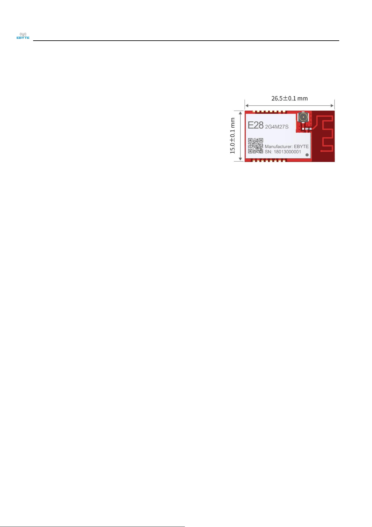
E28-2G4M27S is a 2.4GHz small SMD module (pin spacing
1.27mm)designed by Chengdu Ebyte. With built-in PCB antenna, SPI
interface, it owns TX power of 500mW with power consumption.
The IC SX1280 from Semtech features multiple physical layers and
various modulating methods such as LoRa, FLRC and GFSK, the special
modulating methods and processing ways enable longer operating range
under LoRa and FLRC modulating methods, and the GFSK method covers
BLE protocol. The outstanding ultra-low power consumption and the DC-DC and Time-of-Flight on chip make the chip
much more capable for smart home, security system, tracking and locating, wireless distance measuring, wearable
electronics, smart bracelet and health management & etc.
E28-2G4M27S is a hardware platform without firmware, so users need to conduct secondary development.
1.2 Feature
⚫ Communication distance tested is up to 8km in ideal condition;
⚫ Maximum transmitting power of 27dBm with PA+LNA;
⚫ Compatible with BLE;
⚫ Support the global license-free ISM 2.4GHz;
⚫ Support air data rate of 0.595k~2Mbps;
⚫ Support various modulation such as GFSK Mode,FLRC Mode,LoRa Mode;
⚫ Support 2.5V~3.6V power supply, power supply over 3.3V can guarantee the best performance;
⚫ PCB and IPEX antenna optional, good for secondary and embedded development;
⚫ For high speed usage, under FLRC, it is up to 1.3Mbps;
⚫ Excellent anti-blocking ability;
⚫ With Time-of-flight function, good for ranging;
1.3 Application
⚫ Smart Home and Industrial Sensors;
⚫ Wireless toy and remote control;
⚫ Wireless alarm security system;
⚫ Building automation solutions;
⚫ Wireless industrial-grade remote control;
⚫ Health care products;
⚫ Advanced Meter Reading Architecture(AMI);
⚫ Automotive industry applications.
Page 4
Chengdu Ebyte Electronic Technology Co.,Ltd. E28-2G4M27S User Manual
Copyright ©2012–2019,Chengdu Ebyte Electronic Technology Co.,Ltd.
3
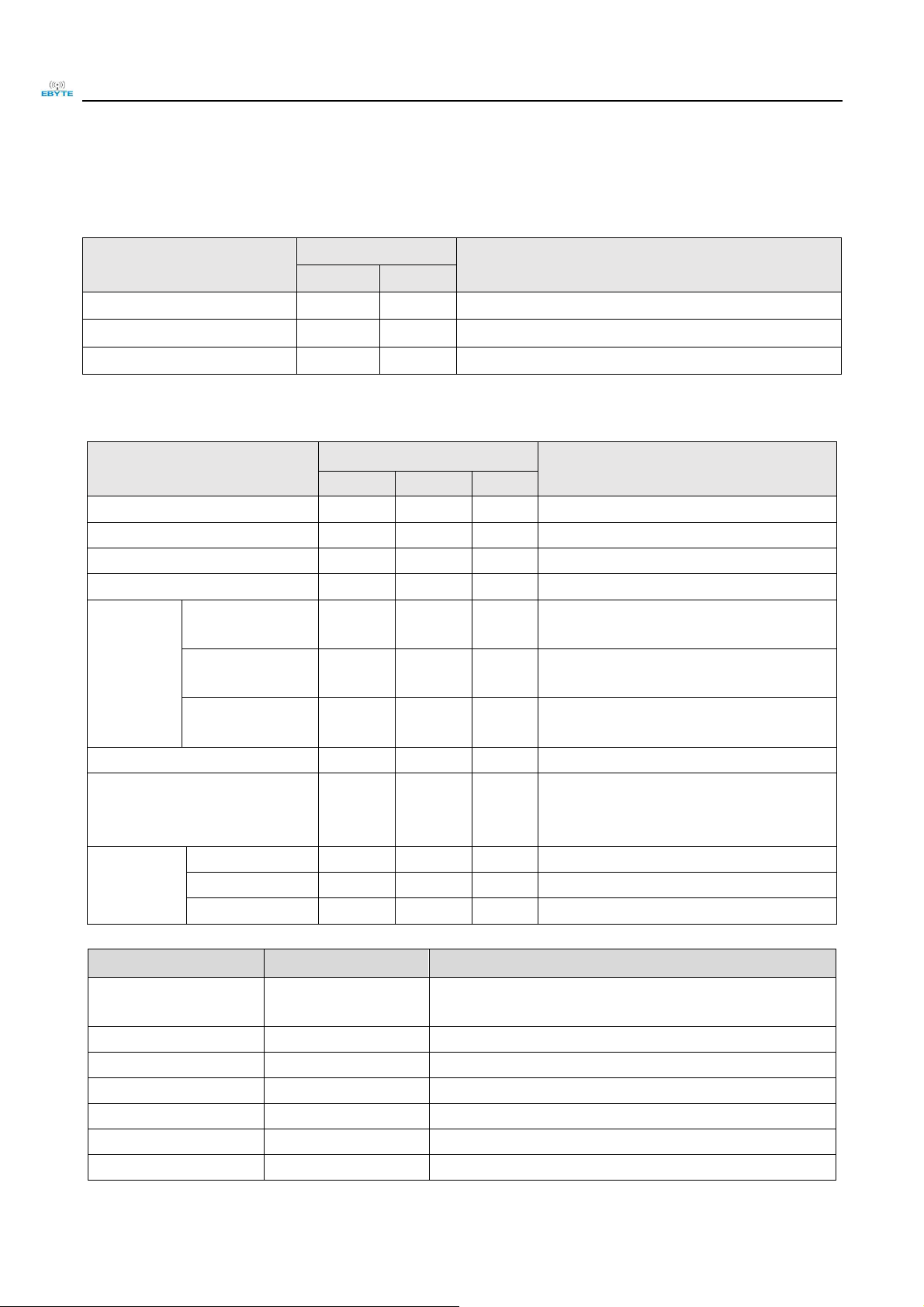
2. Technical Parameters
2.1 Limit parameter
Main parameter
Performance
Note
Min
Max
Voltage supply [V]
0
3.6
Voltage over 3.6V will cause permanent damage to module
Blocking power [dBm]
-
10
Chances of burn is slim when modules are used in short distance
Operating temperature [℃]
-40
+85
-
2.2 Operating parameter
Main parameter
Performance
Note
Min
Typ
Max
Voltage supply [V]
2.5
3.3
3.6
≥3.3 V ensures output power
Communication level [V]
3.3
For 5V TTL, it may be at risk of burning down
Operating temperature [℃]
-40 - +85
-
Frequency [MHz]
2400
2450
2500
ISM band
Power
consumption
Transmitting current
[mA]
580
Instant power consumption
Receiving current
[mA]
14.5
Turn-off current
[μA]
2.0
Software is shut down
Transmitting power [dBm]
26
26.5
27
See more from 4.2
Receiving sensitivity [dBm]
-130
-131
-132
LoRa receiver sensitivity with CR=4/5 and high
sensitivity mode enabled 1
SF12,BW=203kHz
Air data rate
LoRa(bps)
0.595k
-
253.9k
Defined by user via programming
FLRC(bps)
260k
-
1.3M
Defined by user via programming
GFSK(bps)
125k
-
2M
Defined by user via programming
Main parameter
Description
Note
Distance
8000m
Test condition:clear and open area, antenna gain: 5dBi,antenna
height: 2.5m,air data rate: 1kbps
FIFO
256Byte
Max. Transmitting length per packet
Crystal oscillator
52MHz
±10ppm/11pF
Modulation
LoRa [Recommended]
GFSK,FLRC,LoRa
Package
SMD
Connector
1.27mm
Interface
SPI
0~10Mbps
Page 5

Chengdu Ebyte Electronic Technology Co.,Ltd. E28-2G4M27S User Manual
Copyright ©2012–2019,Chengdu Ebyte Electronic Technology Co.,Ltd.
4
Size
15*26.5mm
Antenna
IPEX/PCB
50Ω Impedance
3 Dimension and Pin Definition
No.
Pin item
Pin direction
Application
1
VCC
Power supply, 2.5 ~ 3.6V (recommend to add external ceramic filter capacitor)
2
GND
Ground, connecting to power source reference ground
3
MISO_TX
Output
SPI data output pin, can be used as UART transmitting pin
4
MOSI_RX
Input
SPI data input pin, can be used as UART receiving pin
5
SCK_RTSN
Input
SPI clock input pin, can be used as UART request transmitting pin
6
NSS_CTS
Input
Module chip selection pin, used to start a SPI communication; and can be used as UART
clearing transmitting pin(refer to SX1280 Datasheet for details)
7
GND
Ground, connecting to power source reference ground
8
RX_EN
Input
LNA control pin,valid in high level
9
TX_EN
Input
PA control pin,valid in high level
10
GND
Ground, connecting to power source reference ground
11
NRESET
Input
Chip reset initiation input pin, valid under low level, built-in 50k pull-up resistor
12
BUSY
Output
For status indication(refer to SX1280 Datasheet for details)
13
DIO1
Input/Output
GPIO(refer to SX1280 Datasheet for details)
Page 6

Chengdu Ebyte Electronic Technology Co.,Ltd. E28-2G4M27S User Manual
Copyright ©2012–2019,Chengdu Ebyte Electronic Technology Co.,Ltd.
5
14
DIO2
Input/Output
GPIO(refer to SX1280 Datasheet for details)
15
DIO3
Input/Output
GPIO(refer to SX1280 Datasheet for details)
16
GND
Ground, connecting to power source reference ground
4 Basic Operation
4.1 Hardware design
⚫ It is recommended to use a DC stabilized power supply. The power supply ripple factor is as small as possible, and
the module needs to be reliably grounded;
⚫ Please pay attention to the correct connection of the positive and negative poles of the power supply. Reverse
connection may cause permanent damage to the module;
⚫ Please check the power supply to ensure it is within the recommended voltage otherwise when it exceeds the
maximum value the module will be permanently damaged;
⚫ Please check the stability of the power supply, the voltage can not be fluctuated frequently;
⚫ When designing current supply circuit, 30% margin is recommended to be remained so as to ensure long-term stable
operation of the whole module;
⚫ The module should be as far away as possible from the power supply, transformers, high-frequency wiring and other
parts with large electromagnetic interference;
⚫ High-frequency digital routing, high-frequency analog routing, and power routing must be avoided under the module.
If it is necessary to pass through the module, assume that the module is soldered to the Top Layer, and the copper is
spread on the Top Layer of the module contact part(well grounded), it must be close to the digital part of the module
and routed in the Bottom Layer;
⚫ Assuming the module is soldered or placed over the Top Layer, it is wrong to randomly route over the Bottom Layer
or other layers, which will affect the module's spurs and receiving sensitivity to varying degrees;
⚫ It is assumed that there are devices with large electromagnetic interference around the module that will greatly affect
the performance. It is recommended to keep them away from the module according to the strength of the interference.
If necessary, appropriate isolation and shielding can be done;
⚫ Assume that there are traces with large electromagnetic interference (high-frequency digital, high-frequency analog,
power traces) around the module that will greatly affect the performance of the module. It is recommended to stay
away from the module according to the strength of the interference.If necessary, appropriate isolation and shielding
can be done;
⚫ If the communication line uses a 5V level, a 1k-5.1k resistor must be connected in series (not recommended, there is
still a risk of damage);
⚫ Try to stay away from some physical layers such as TTL protocol at 2.4GHz , for example: USB3.0;
⚫ The antenna installation position has a great influence on the performance of the module. Make sure that the antenna
is exposed, preferably vertically. When the module is installed inside the shield, a high-quality antenna extension
cable can be used to extend the antenna outside;
⚫ The antenna must not be installed inside the metal case, which will greatly reduce the transmission distance.
Page 7

Chengdu Ebyte Electronic Technology Co.,Ltd. E28-2G4M27S User Manual
Copyright ©2012–2019,Chengdu Ebyte Electronic Technology Co.,Ltd.
6
4.2 Software editing
⚫ With SX1280+PA+LNA,its driving method is similar to SX1280, please refer to SX1280 datasheet for operation guidance;
⚫ GDO0 is GPIO,refer to SX1280 datasheet for details;
⚫ GDO2 is generally configured as an IRQ-like function, or it can be disconnected. The SPI query mode can be used to obtain the
interrupt status, but it is recommended to use the external interrupt via connecting MCU;
⚫ After the SX1280 restores the IDLE mode or configured in sleep mode, it is recommended to reinitialize the power configuration
table;
⚫ It is recommended that the power output parameter of the SX1280 be set to 0dBm. At this time, the module outputs 27dBm. When
the output power of the SX1280 is increased, the current will become larger and the power will not increase significantly.
5 Basic Application
5.1 Circuit Diagram
Page 8

Chengdu Ebyte Electronic Technology Co.,Ltd. E28-2G4M27S User Manual
Copyright ©2012–2019,Chengdu Ebyte Electronic Technology Co.,Ltd.
7
6. FAQ
6.1 Communication range is too short
⚫ The communication distance will be affected when obstacle exists.
⚫ Data lose rate will be affected by temperature, humidity and co-channel interference.
⚫ The ground will absorb and reflect wireless radio wave, so the performance will be poor when testing near ground.
⚫ Seawater has great ability in absorbing wireless radio wave, so performance will be poor when testing near the sea.
⚫ The signal will be affected when the antenna is near metal object or put in a metal case.
⚫ Power register was set incorrectly, air data rate is set as too high (the higher the air data rate, the shorter the distance).
⚫ When the power supply at room temperature is lower than the recommended low voltage, the lower the voltage is,
the lower the transmitting power is.
⚫ Due to antenna quality or poor matching between antenna and module.
6.2 Module is easy to damage
⚫ Please check the power supply and ensure it is within the recommended range. Voltage higher than the peak will lead
to a permanent damage to the module.
⚫ Please check the stability of power supply and ensure the voltage not to fluctuate too much.
⚫ Please make sure anti-static measures are taken when installing and using, high frequency devices have electrostatic
susceptibility.
⚫ Please ensure the humidity is within limited range for some parts are sensitive to humidity.
⚫ Please avoid using modules under too high or too low temperature.
6.3 Bit error rate is too high
⚫ When there are co-channel signal interference nearby, be away from interference sources or modify frequency and
channel to avoid interference;
⚫ The clock waveform on the SPI is not standard. Check whether there is interference on the SPI line. The SPI bus
should not be too long.
⚫ Unfavorable power supply may cause messy code. Make sure that the power supply is reliable.
⚫ Extension line and feeder with poor quality or too long ones will cause high bit error rate.
Page 9

Chengdu Ebyte Electronic Technology Co.,Ltd. E28-2G4M27S User Manual
Copyright ©2012–2019,Chengdu Ebyte Electronic Technology Co.,Ltd.
8
7. Production Guidance
7.1 Reflow Soldering Temperature
Profile Feature
Sn-Pb Assembly
Pb-Free Assembly
Solder Paste
Sn63/Pb37
Sn96.5/Ag3/Cu0.5
Preheat Temperature min (Tsmin)
100℃
150℃
Preheat temperature max (Tsmax)
150℃
200℃
Preheat Time (Tsmin to Tsmax)(ts)
60-120 sec
60-120 sec
Average ramp-up rate(Tsmax to Tp)
3℃/second max
3℃/second max
Liquidous Temperature (TL)
183℃
217℃
Time(tL)Maintained Above(TL)
60-90 sec
30-90 sec
Peak temperature(Tp)
220-235℃
230-250℃
Aveage ramp-down rate(Tp to Tsmax)
6℃/second max
6℃/second max
Time 25℃ to peak temperature
6 minutes max
8 minutes max
7.2 Reflow Soldering Curve
Page 10

Chengdu Ebyte Electronic Technology Co.,Ltd. E28-2G4M27S User Manual
Copyright ©2012–2019,Chengdu Ebyte Electronic Technology Co.,Ltd.
9
8 E28 Series
Model
IC
Frequency
TX power
Distance
Size
Package
Interface
Hz
dBm
km
mm
E28-2G4T12S
SX1280
2.4G
12.5
3
17.5*28.7
SMD
TTL
E28-2G4M27S
SX1280
2.4G
27
8
15*26.5
SMD
SPI
E28-2G4M20S
SX1280
2.4G
20
6
15*26.5
SMD
SPI
E28-2G4M12S
SX1280
2.4G
12.5
3
25*14
SMD
SPI
9 Antenna Guidance
9.1 Antenna recommendation
Antenna plays an important role in the communication process. Inferior antennas often have a great impact on the
communication system. Therefore, we recommend some antennas that support our wireless modules and have excellent
performance and reasonable price.
Model
Type
Frequency
Gain
Size
Feeder
Interface
Feature
Hz
dBi
mm
cm
TX2400-NP-5010
FPC
2.4G
2.0
10x50 - IPEX
FPC antenna
TX2400-JZ-3
Rubber
2.4G
2.0
30 - SMA-J
Straight antenna,ultra short
TX2400-JZ-5
Rubber
2.4G
2.0
50 - SMA-J
Straight antenna,ultra short
TX2400-JW-5
Rubber
2.4G
2.0
50 - SMA-J
Fixed bending antenna
TX2400-JK-11
Rubber
2.4G
2.5
110 - SMA-J
Flexible antenna,omnidirectional
TX2400-JK-20
Rubber
2.4G
3.0
200 - SMA-J
Flexible antenna,omnidirectional
TX2400-XPL-150
Sucker
2.4G
3.5
150
150
SMA-J
Small sucker antenna,high gain
9.2 Antenna selection
PCB(Default) IPEX
Page 11

Chengdu Ebyte Electronic Technology Co.,Ltd. E28-2G4M27S User Manual
Copyright ©2012–2019,Chengdu Ebyte Electronic Technology Co.,Ltd.
10
Revision history
Version
Date
Description
Operator
1.0
2019-02-28
Initial Version
Ray
1.1
2019-04-04
Content Update
Ray
About us
Website: www.ebyte.com Sales: info@cdebyte.com Support: support@cdebyte.com
Tel: +86-28-61399028 Ext. 812 Fax: +86-28-64146160
Address: Innovation Center B333~D347, 4# XI-XIN road,High-tech district (west), Chengdu, Sichuan, China
 Loading...