

Page 1
E28-2G4M12S User Manual
SX1280 2.4GHz SMD Wireless Module
Page 2

Chengdu Ebyte Electronic Technology Co., Ltd. E28-2G4M12S User Manual
Copyright ©2012–2018,Chengdu Ebyte Electronic Technology Co., Ltd. 1
目录
1. Overview................................................................................................................................................................................................2
1.1 Brief introduction ......................................................................................................................................................................2
1.2 Features .......................................................................................................................................................................................2
1.3 Application .................................................................................................................................................................................2
2.Spec ification and para meter ................................................................................................................................................................3
2.1 Limit parameter .........................................................................................................................................................................3
2.2 Operating para meter .................................................................................................................................................................3
3.Size and pin definition ..........................................................................................................................................................................4
4.Basic operation.......................................................................................................................................................................................5
4.1 Hardware design ................................................................................................................................................................5
4.2 Software ed iting ........................................................................................................................................................................5
5.Basic application .........................................................................................................................................................................6
5.1 Basic circuit diagram ................................................................................................................................................................6
6.FA Q..........................................................................................................................................................................................................6
6.1 Communication range is too short .........................................................................................................................................6
6.2 Module is easy to damage........................................................................................................................................................7
6.3 BER(Bit Error Rate) is high ....................................................................................................................................................7
7.Production guidance..............................................................................................................................................................................7
7.1 Reflow soldering te mperature .................................................................................................................................................7
7.2 Reflow soldering curve ............................................................................................................................................................8
8.E28 Series ...............................................................................................................................................................................................8
9.Antenna guidance ..................................................................................................................................................................................9
9.1 Antenna recommendation ........................................................................................................................................................9
9.2 Antenna selection ......................................................................................................................................................................9
Revision history ..................................................................................................................................................................................... 10
About us .................................................................................................................................................................................................. 10
Page 3

Chengdu Ebyte Electronic Technology Co., Ltd. E28-2G4M12S User Manual
Copyright ©2012–2018,Chengdu Ebyte Electronic Technology Co., Ltd. 2
1. Overview
1.1 Brief introduction
E28-2G4M12S is a 2.4GHz bluetooth module designed by Chengdu Ebyte,with long distance and ultra -low power
consumption. E28-2G4M12S is small-sized SMD module(pin spacing 1.27mm),built-in PCB antenna and IPEX antenna.
High precision 52MHz crystal is used.
Based on the original imported RF chip SX1278 from SEMTECH,T h e
IC SX1280 features multiple physical layers and various modulating
methods such as LoRa, FLRC and GFSK, the special modulating methods
and processing ways enable longer operating range under LoRa and FLRC
modulating methods, and the GFSK method covers BLE protocol. The
outstanding ultra-low power consumption and the DC-DC and Time-of-
Flight on chip make the chip much more capable for smart home, security
system, tracking and locating, wireless d istance measuring, wearable
electronics, smart bracelet and health management & etc. SX1280 supports RSSI,users need to conduct a secondary
development based on their own demands ;SX1280 also integrates time of flight for ranging functions .
Since the module is a pure RF trans ceiver module, you need to use the MCU driver or a dedicated SPI debug tool.
1.2 Features
Communication distance tested is up to 3km;
Maximum transmission power of 18mW, software multi-level adjustable;
Compatible with BLE protocol;
Support the global licens e-free ISM 2.4GHz band;
Support air date rate of 0.476kbps ~2Mbps;
Support multiple modulation methods, (GFSK Mode ,FLRC Mode,LoRa Mode);
Large capacity FIFO, s upports 256Byte data buffer;
Support 1.8V~3.6V power supply, power supply over 3.3V can guarantee the best performance ;
Industrial grade s tandard design, support -40 ~ 85 °C for working over a long time;
IPEX and PCB antenna optional, good for s econdary development and integration ;
The air data rate is adjustable, the maximu m air data rate is up to 1.3 Mbps in FLRC mode;
Excellent anti-blocking properties;
Ranging, with Time-of-flight function.
1.3 Application
Home s ecurity alarm and remote keyless entry;
Smart home and industrial sensors ;
Wireless alarm security system;
Building automation solutions ;
Wireless industrial-grade remote control;
Health care products;
Advanced Meter Reading Architecture(AMI);
Automotive industry applications.
Page 4
Chengdu Ebyte Electronic Technology Co., Ltd. E28-2G4M12S User Manual
Copyright ©2012–2018,Chengdu Ebyte Electronic Technology Co., Ltd. 3
2.Specification and parameter
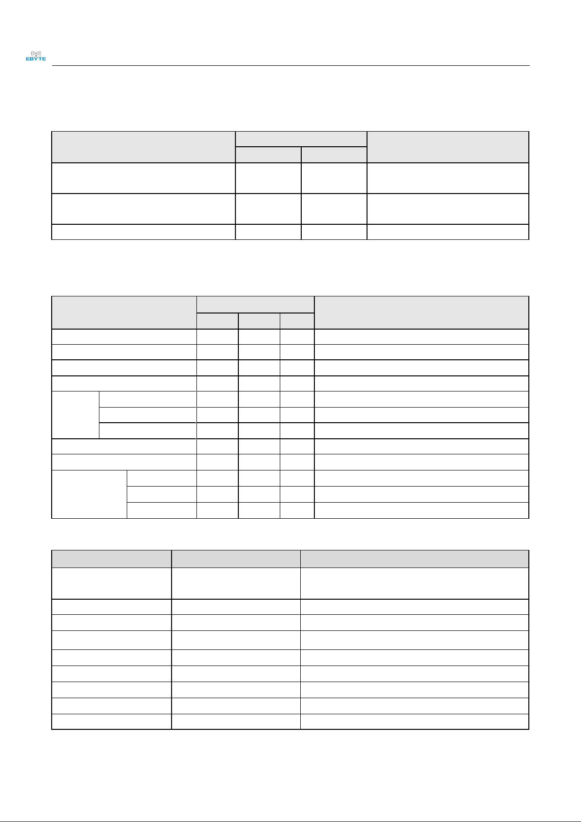
2.1 Limit parameter
Main parameter
Performance
Remark
Min.
Max.
Power supply(V)
0
3.6
Voltage over 3.6V will cause permanent
damage to module
Blocking power(dBm)
-
10
Chances of burn is slim when modules are
used in short distance
Operating temperature(℃)
-40
85
-
2.2 Operating parameter
Main parameter
Performance
Remark
Min.
Typ.
Max.
Operating voltage(V)
1.8
3.3
3.6
≥3.3 V ensures output power
Communication level(V)
-
3.3
-
For 5V TTL, it may be at risk of burning down
Operating temperature(℃)
-40 - 85
Industrial design
Operating frequency(MHz)
2400
2430
2500
Support ISM band
Power
consumpti
on
TX current(mA)
-
45
-
Instant power consumption
RX current(mA)
-
10
-
-
Sleep current (μA )
-
2.0
-
Software is shut down
Max Tx power(dBm)
12
12.5
14
-
Receiving sensitivity(dBm)
-126
-128
-130
air data rate:595kbps
Air data rate
LoRa24(bps)
0.476k
-
202K
Programming
FLRC(bps)
130k
-
1.3M
Programming
FSK(bps)
125k
-
2M
Programming
Main parameter
Description
Remark
Distance for reference
3000m
Test condition:clear and open area, antenna gain: 5dBi,
antenna height: 2.5m,air data rate: 595kbps
FIFO
256Byte
Max length transmitted each time
Crystal frequency
52MHz
-
Modulation
LoRaTM (recommended)
GFSK Mode ,FLRC Mode,LoRa Mode
Package
SMD
-
Connector
1.27mm
IPEX/PCB
Communication interface
SPI
0-10Mbps
Size
25* 14*0.8 mm
-
Antenna
Stamp hole
50 ohm impedance
Page 5

Chengdu Ebyte Electronic Technology Co., Ltd. E28-2G4M12S User Manual
Copyright ©2012–2018,Chengdu Ebyte Electronic Technology Co., Ltd. 4
3.Size and pin definition
Pin No
Pin item
Pin direction
Pin application
1
VCC
-
Power sup p ly: 1.8~3.6V (Ceramic filter capacitor is advised to add)
2
GND
-
Ground, connecting to power supp ly reference ground
3
MISO_TX
Output
SPI data output pin,can be used as UART transmitting pin
4
MOSI_RX
Input
SPI data input pin,can be used as UART receiving p in
5
SCK_RTSN
Input
SPI clock input pin,can be used as UART request transmitt ing pin
6
NSS_CTS
Input
Module chip selection pin, used to start a SPI communication; and can be used as
UART clearing transmitting pin(refer to SX1280 Datasheet)
7
GND
-
Ground, connecting to power supp ly reference ground
8
GND
-
Ground, connecting to power supp ly reference ground
9
NRESET
Input
Chip reset initiation input pin, valid under low level, built-in 50k pull-up resistor
10
BUSY
Output
Status indication (refer to SX1280 Datasheet)
11
DIO1
Input / Output
Configurable IO p ort (Please find more on SX1280 datasheet)
12
DIO2
Input / Output
Configurable IO p ort (Please find more on SX1280 datasheet)
13
DIO3
Input / Output
Configurable IO p ort (Please find more on SX1280 datasheet)
14
GND
-
Ground, connecting to power supp ly reference ground
Page 6

Chengdu Ebyte Electronic Technology Co., Ltd. E28-2G4M12S User Manual
Copyright ©2012–2018,Chengdu Ebyte Electronic Technology Co., Ltd. 5
4.Basic operation
4.1 Hardware design
It is recommended to use a DC stabilized power s upply. The power supply ripple factor is as small as possible, and
the module needs to be reliably grounded.;
Please pay attention to the correct connection of the positive and negative poles of the power supply. Reverse
connection may cause permanent damage to the module;
Please check the power supply to ensure it is within the recommended voltage otherwise when it exceeds the
maximum value the module will be permanently damaged ;
Please check the stability of the power supply, the voltage can not be fluctuated frequently ;
When designing the power s upply circuit for the module, it is often recommended to reserve more than 30% of the
margin, s o the whole machine is beneficial for long-term stable operation.;
The module should be as far away as pos s ible from the power supply, transformers, high -frequency wiring and other
parts with large electromagnetic interference.;
High-frequency digital routing, high-frequency analog routing, and power routing must be avoided under the module.
If it is neces s ary to pass through the module, assume that the module is soldered to the Top Layer, and the copper is
spread on the Top Layer of the module contact part(well grounded), it must be close to the digital part of the module
and routed in the Bottom Layer;
As suming the module is soldered or placed over the Top Layer, it is wrong to randomly route over the Bottom Layer
or other layers, which will affect the module's spurs and receiving s ensitivity to varying degrees ;
It is assumed that there are devices with large electromagnetic interference around the module that will greatly affe ct
the performance. It is recommended to keep them away from the module according to the strength of the interference.
If necessary, appropriate isolation and s hielding can be done;
As sume that there are traces with large electromagnetic interference (high -frequency digital, high-frequency analog,
power traces) around the module that will greatly affect the performance of the module. It is recommended to stay
away from the module according to the strength of the interference.If neces sary, appropriate isolation and shielding
can be done.
If the communication line uses a 5V level, a 1k-5.1k resistor must be connected in series (not recommended, there is
still a risk of damage);
Try to s tay away from some phys ical layers such as TTL protocol at 2.4GHz , for example: USB3.0;
The mounting structure of antenna has a great influence on the performance of the module. It is necessary to ensure
that the antenna is expos ed, preferably vertically upward. When the module is mounted inside the case, use a good
antenna extension cable to extend the antenna to the outside;
The antenna must not be installed inside the metal case, which will caus e the transmission distance to be greatly
weakened.
4.2 Software editing
This module is based on SX1280,same drive way as SX1280,user can refer to SX1280 datasheet.
DIO is general I/O port,s ee more in SX1280 datasheet.
GDO 2 is generally configurated as IRQ function, IRQ pin can also be disconnected. The SPI query mode can be used
Page 7

Chengdu Ebyte Electronic Technology Co., Ltd. E28-2G4M12S User Manual
Copyright ©2012–2018,Chengdu Ebyte Electronic Technology Co., Ltd. 6
to obtain the interrupt status . However, it is recommended to us e the external interrupt of the MCU.
After SX1280 restores IDLE mode or configures sleep mode, it is recommended that the power configuration table
be reinitialized.
5.Basic application
5.1 Basic circuit diagram
6.FAQ
6.1 Communication range is too short
The communication distance will be affected when obstacle exists.
Data lose rate will be affected by temperature, humidity and co -channel interference.
The ground will absorb and reflect wireless radio wave, so the performance will be poor when tes ting near groun d.
Sea water has great ability in absorbing wireless radio wave, so performance will be poor when tes ting near the sea.
The signal will be affected when the antenna is near metal object or put in a metal cas e.
Page 8

Chengdu Ebyte Electronic Technology Co., Ltd. E28-2G4M12S User Manual
Copyright ©2012–2018,Chengdu Ebyte Electronic Technology Co., Ltd. 7
Power register was set incorrectly, air data rate is set as too high (the higher the air data rate, the shorter the
distance).
The power s upply low voltage under room temperature is lower than 2.5V, the lower the voltage, the lower the
trans mitting power.
Due to antenna quality or poor matching between antenna and module.
6.2 Module is easy to damage
Please check the power s upply source, ens ure it is 2.0V~3.6V, voltage higher than 3.6V will damage the module.
Please check the stability of power source, the voltage cannot fluctuate too much.
Please make sure antistatic measure are taken when installing and using, high frequency devices have electros tatic
susceptibility.
Please ensure the humidity is within limited range, s ome parts are sensitive to humidity.
Please avoid us ing modules under too high or too low temperature.
6.3 BER(Bit Error Rate) is high
There are co-channel signal interference nearby, please be away from interference s ources or modify frequency a nd
channel to avoid interference;
Poor power supply may cause mess y code. Make s ure that the power supply is reliable.
The extension line and feeder quality are poor or too long, so the bit error rate is high;
7.Production guidance
7.1 Reflow soldering temperature
Profile Feature
Curve characteristics
Sn-Pb Assembly
Pb-Free Assembly
Solder Paste
Solder paste
Sn63/Pb37
Sn96.5/Ag3/Cu0.5
Preheat Temperature min (Tsmin)
Min preheating temp.
100℃
150℃
Preheat temperature max (Tsmax)
Mx preheating temp.
150℃
200℃
Preheat Time (Tsmin to Tsmax)(ts)
Preheating time
60-120 sec
60-120 sec
Average ramp-up rate(Tsmax to Tp)
Average ramp-up rate
3℃/second max
3℃/second max
Liquidous Temperature (TL)
Liquid phase temp.
183℃
217℃
Time(tL)Maintained Above(TL)
Time below liquid phase line
60-90 sec
30-90 sec
Peak temperature(Tp )
Peak temp.
220-235℃
230-250℃
Aveage ramp-down rate(Tp to Tsmax)
Aveage ramp-down rate
6℃/second max
6℃/second max
Time 25℃ to peak temperature
Time to peak temperature
for 25℃
max 6 minutes
max 8 minutes
Page 9

Chengdu Ebyte Electronic Technology Co., Ltd. E28-2G4M12S User Manual
Copyright ©2012–2018,Chengdu Ebyte Electronic Technology Co., Ltd. 8
7.2 Reflow soldering curve
8.E28 Series
Model No.
IC
Frequency
(Hz)
Tx power
(dBm)
Test distance
(km)
Package
Size
Antenna
E28-2G4M20S
SX1280
2.4G
20
6
SMD
15 * 26.5
IPEX/PCB
E28-2G4M12S
SX1280
2.4G
12.5
3
SMD
25*14
IPEX/PCB
E28-2G4T12S
SX1280
2.4G
12.5
3
SMD
17.5* 28.7
IPEX/PCB
Page 10

Chengdu Ebyte Electronic Technology Co., Ltd. E28-2G4M12S User Manual
Copyright ©2012–2018,Chengdu Ebyte Electronic Technology Co., Ltd. 9
9.Antenna guidance
9.1 Antenna recommendation
The antenna is an important role in the communication process. A good antenna can largely improve the
communication s ystem. Therefore, we recommend some antennas for wireless modules with excellent performance and
reasonable price.
Model No.
Type
Frequency
Hz
Interface
Gain
dBi
Height
Cable
Function feature
TX2400-NP-5010
FCB antenna
2.4G
SMA-J
2
50*10mm
-
FPC soft antenna
TX2400-XP-150
Sucker
2.4G
SMA-J
3.5
15cm
150cm
Sucker antenna, High
gain
TX2400-JK-20
Rubber
2.4G
SMA-J
3
200mm
-
Flexible
&omnidirectional
TX2400-JK-11
Rubber
2.4G
SMA-J
2.5
110mm
-
Flexible
&omnidirectional
TX2400-JZ-3
Rubber
2.4G
SMA-J
2
30mm
-
Short straight
&omnidirectional
9.2 Antenna selection
PCB (default) IPEX
Page 11

Chengdu Ebyte Electronic Technology Co., Ltd. E28-2G4M12S User Manual
Copyright ©2012–2018,Chengdu Ebyte Electronic Technology Co., Ltd. 10
Revision history
Version
Date
Description
Issued by
1.00
2017/10/16
Initial version
huaa
1.10
2018/5/23
Content updated
huaa
1.20
2018/9/21
Model No. split
Huaa
About us
Technical support: s upport@cdebyte.com
Documents and RF Setting download link: www.ebyte.com
Thank you for us ing Ebyte products! Please contact us with any questions or s uggestions: info@cdebyte.com
--------------------- -- --- -- -- -- --- -- -- --------------------------------------- -- -- -- --- -- -- -- --- -
Fax: 028-64146160 ext. 821
Web: www.ebyte.com
Address: Innovation Center D347, 4# XI-XIN Road,Chengdu, Sichuan, China
 Loading...