

Page 1
E18-MS1PA1-IPX User Manual
CC2530 2.4GHz ZigBee 100mW SMD Wireless Module
Page 2

Chengdu Ebyte Electronic Technology Co., Ltd. E18-MS1PA1-IPX User Manual
Copyright ©2012–2018,成都亿佰特电子科技有限公司 1
Contents
1 General Introduction ................................................................................................................................................................................... 2
1.1 Brief Introduction ............................................................................................................................................................................ 2
1.3 Application ........................................................................................................................................................................................ 2
2 Specification and parameter ...................................................................................................................................................................... 3
2.1 limit parameter ................................................................................................................................................................................. 3
2.2 Operating parameter ....................................................................................................................................................................... 3
3 Size and pin definition ................................................................................................................................................................................ 4
4 Usage .............................................................................................................................................................................................................. 5
5 Programming ................................................................................................................................................................................................. 7
5.1 TI ZigBee FAQ ................................................................................................................................................................................ 7
6 Basic operation ........................................................................................................................................................................................... 10
6.1 Hardware design ............................................................................................................................................................................ 10
6.2 Programming .................................................................................................................................................................................. 11
7 FAQ ............................................................................................................................................................................................................... 11
7.1 Communication range is too short ............................................................................................................................................ 11
7.2 Module is easy to damage ........................................................................................................................................................... 12
7.3 BER(Bit Error Rate) is high ....................................................................................................................................................... 12
8 Production guidance .................................................................................................................................................................................. 12
8.1 Reflow soldering temperature .................................................................................................................................................... 12
8.2 Reflow soldering curve ................................................................................................................................................................ 13
9 E18 series ..................................................................................................................................................................................................... 13
10 Antenna recommendation ...................................................................................................................................................................... 13
10.1 Recommendation ........................................................................................................................................................................ 13
11 Package ...................................................................................................................................................................................................... 14
Revision history ............................................................................................................................................................................................. 15
About us ........................................................................................................................................................................................................... 15
Page 3
Chengdu Ebyte Electronic Technology Co., Ltd. E18-MS1PA1-IPX User Manual
Copyright ©2012–2018,成都亿佰特电子科技有限公司 2
1 General Introduction
1.1 Brief Introduction
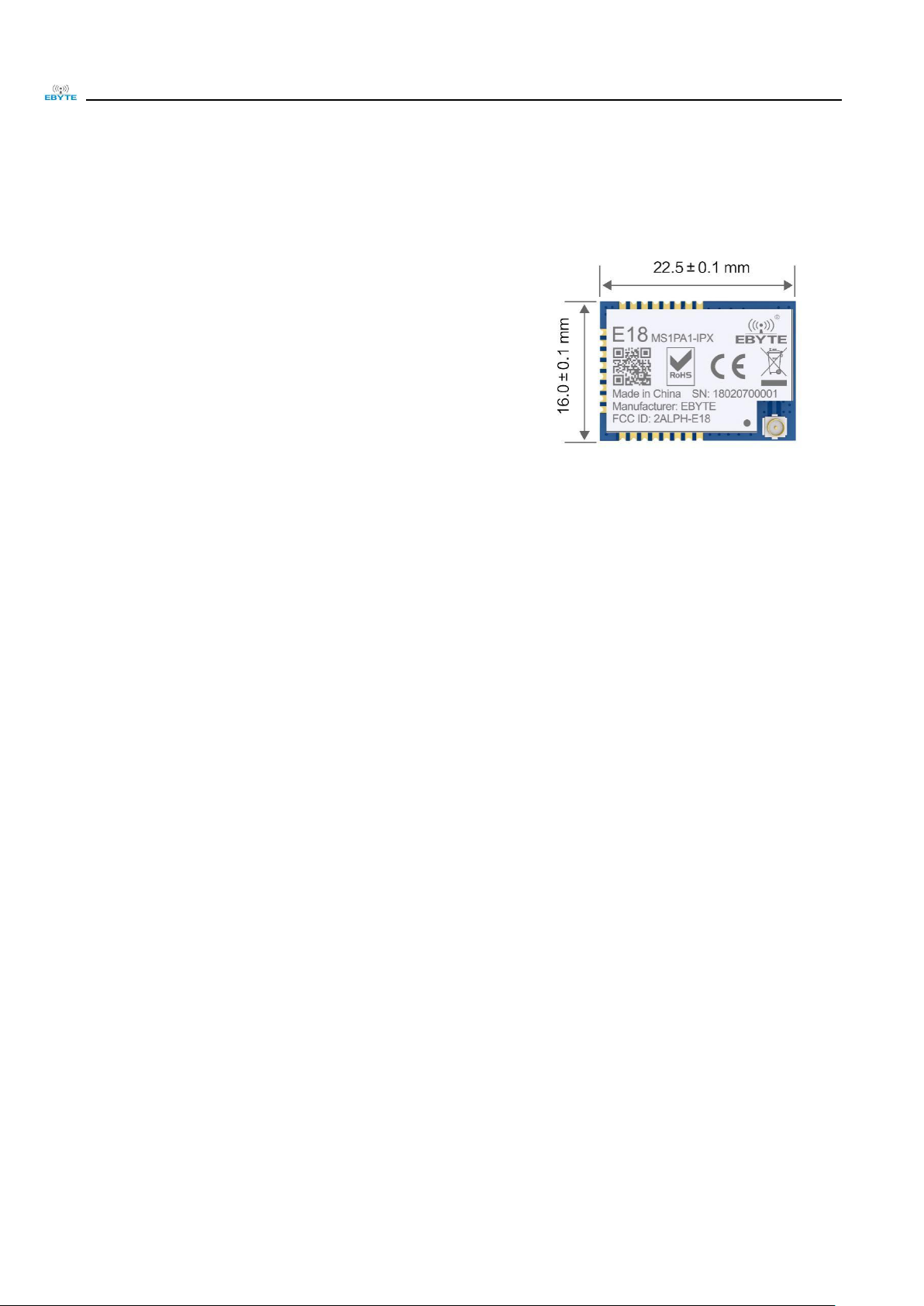
E18-MS1PA1-IPX is small-sized 2.4GHz SMD wireless module,
which is designed and produced by Chengdu Ebyte. The space between
each pin is 1.27mm. E18-MS1-IPX has been put into stable bulk
production, it is applicable for various applications (especially smart
home).
E18-MS1PA1-IPX adopts the original CC2530 RF chip of TI, the
chip is integrated with 8051 MCU and wireless transceiver. The chip
integrates 8051 MCU and wireless transceiver, and built-in CC2592 RF
range extender with integrated PA+LNA, greatly expanding communication distance and improving communication
stability.The module is applicable for ZigBee design and 2.4GHz IEEE 802.15.4 protocol. All IO ports of the MCU have
been pinned out for multiple development.
1.2 Features
The measured communication distance is up to 1000 m;
Maximum transmission power of 100mW, software multi-level adjustable;
Built-in ZigBee protocol stack;
Factory-installed self-organizing network firmware, ready to use;
Support peripherals such as ADC, PWM, GPIO;
Support UART transparent transmission, easy to use;
Built-in 32.768kHz clock crystal oscillator;
Support the global license-free ISM 2.4GHz band;
Rich resources, 256KB FLASH,8KB RAM;
Built-in CC2592 RF range extender with integrated PA+LNA;
Support 2.0V~3.6Vpower supply,power supply over 3.3Vcan guarantee the best performance;
Industrial grade standard design, support -40 ~ 85 °C for working over a long time;
IPEX interface for easy connection to coaxial cable or external antenna.
1.3 Application
Smart homes and industrial sensors;
Security system, positioning system;
Wireless remote control, drone;
Wireless game remote control;
Health care products;
Wireless voice, wireless headset;
Automotive industry applications.
Page 4
Chengdu Ebyte Electronic Technology Co., Ltd. E18-MS1PA1-IPX User Manual
Copyright ©2012–2018,成都亿佰特电子科技有限公司 3
2 Specification and parameter
2.1 limit parameter
Main parameter
Performance
Remark
Min
Max
Power supply (V)
0
3.6
Voltage over 3.6V will cause
permanent damage to module
Blocking power(dBm)
-
10
Chances of burn is slim when
modules are used in short distance
Operating temperature(℃)
-40
85
-
2.2 Operating parameter
Main parameter
Performance
备注
Min
Type
Max
Operating voltage(V)
2.0
3.3
3.6
≥3.3 V ensures output power
Communication level (V)
-
3.3
-
For 5V TTL, it may be at risk of
burning down
Operating temperature (℃)
-40 - 85
Industrial grade
Operating frequency(GHz)
2.400
-
2.480
Support ISM band
Power
Consu
m-ption
TX current(mA)
-
140
-
Instant power consumption
RX current(mA)
-
42
-
-
Sleep current(μA)
-
1.2
-
Shut down by software
Max TX power(dBm)
19.6
20.0
20.5
-
Receiving sensitivity(dBm)
-96.5
-97.6
-98.5
Air data rate is 250 kbps
Main parameter
Description
备注
Reference distance
1000 m
Test condition:clear and open area, antenna gain:
5dBi, antenna height: 2.5m,air data rate: 250 kbps
Protocol
ZigBee
-
Package
SMD
-
Interface
1.27mm
-
IC
CC2530F256RHAT/QFN40
Built-in CC2592 RF range extender with integrated
PA+LNA
FLASH
256 KB
-
RAM
8 KB
-
Core
8051microcontroller
-
Page 5
Chengdu Ebyte Electronic Technology Co., Ltd. E18-MS1PA1-IPX User Manual
Copyright ©2012–2018,成都亿佰特电子科技有限公司 4
Main parameter
16.0 * 22.5 mm
-
Antenna
IPEX
50 ohm impedance
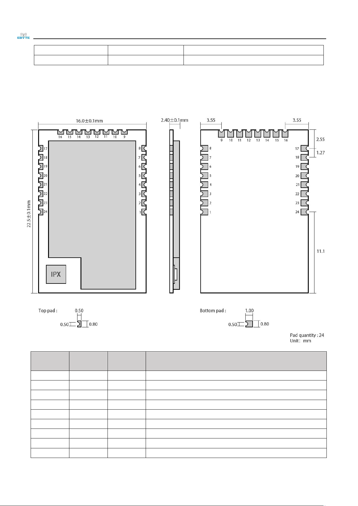
3 Size and pin definition
Pin No.
Pin item
Pin
direction
Application
1
GND
Input
Ground, connecting to power source referential ground
2
VCC
Input
Power supply, must be 2.0 ~ 3.6V
3
P2.2
Input/Output
MCU GPIO
4
P2.1
Input/Output
MCU GPIO
5
P2.0
Input/Output
MCU GPIO
6
P1.7
Input/Output
MCU GPIO
7
P1.6
Input/Output
MCU GPIO
8
NC
-
Reserved
9
NC
-
Reserved
Page 6

Chengdu Ebyte Electronic Technology Co., Ltd. E18-MS1PA1-IPX User Manual
Copyright ©2012–2018,成都亿佰特电子科技有限公司 5
10
P1.5
Input/Output
MCU GPIO
11
P1.4
Input/Output
MCU GPIO
12
P1.3
Input/Output
MCU GPIO
13
P1.2
Input/Output
MCU GPIO
14
P1.1
Output
MCU GPIO, PA transmitting control pin
15
P1.0
Output
MCU GPIO, PA receiving control pin
16
P0.7
Output
MCU GPIO, PA receiving high gain control pin
17
P0.6
Input/Output
MCU GPIO
18
P0.5
Input/Output
MCU GPIO
19
P0.4
Input/Output
MCU GPIO
20
P0.3
Input/Output
MCU GPIO
21
P0.2
Input/Output
MCU GPIO
22
P0.1
Input/Output
MCU GPIO
23
P0.0
Input/Output
MCU GPIO
24
RESET
Input
Reset port
For the IO function, please go to the official website to download "E18_Software_Datasheet_CN";
For secondary development, please refer to TI's official "CC2530 Datasheet" for pin definition, software driver and
communication protocol.
4 Usage
No.
Keyword
Remark
1
Burn
firmware
The module is with built-in 8051 MCU,to download program please use downloader CC
Debugger
2
Initiate PA
Initiate PA , modify it in file hal_board_cfg.h.
Page 7

Chengdu Ebyte Electronic Technology Co., Ltd. E18-MS1PA1-IPX User Manual
Copyright ©2012–2018,成都亿佰特电子科技有限公司 6
3
Parameter
setting
The setting of CC2592 in zstack,CC2530 pin: P1.1、P1.0、P0.7 are connected with CC2592
pin :PA_EN、LNA_EN、HGM. Meanwhile, LNA_EN is in high level,and it is in receiving
mode.
4
Program
modificati
-on
Find macRadioTurnOnPower() from mac_radio_defs.c,and modify.
Page 8

Chengdu Ebyte Electronic Technology Co., Ltd. E18-MS1PA1-IPX User Manual
Copyright ©2012–2018,成都亿佰特电子科技有限公司 7
5
Power
modificati
-on
Find static CODE const macPib_t macPibDefaults from file mac_pib.c. Modify in the red
signed below.
5 Programming
You are recommended to use the Code Composer Studio (CCS) integrated development environment (IDE) applicable
for wireless.
Code Composer Studio is a kind of IDE, it supports TI MCU and embedded processor series products. Code Composer
Studio covers a whole set of tools for development and embedded application. It covers the C/C++ compiler for optimizing,
source code editor, project building environment, debugger, descriptor and many other functions. The IDE provides
individual user interface, it can help you complete every step in developing. Familiar tool and interface enables users t o
start more quickly. Code Composer Studio integrates the advantages of Eclipse software frame and the embedded
debugging function of TI and provides a knockout and functionable development environment.
5.1 TI ZigBee FAQ
How to select proper protocol stack from different ZigBee protocol stacks of TI?
From the Z-Stack 0.1 to Z-Stack 2.5.1a and the current Z-Stack Home 1.2.1, Z-Stack Lighting 1.0.2, Z-Stack Energy
1.0.1, Z-Stack Mesh 1.0.0, TI mainly upgraded the protocol stack through: 1) adding some new features according to
ZigBee Specification of the ZigBee Alliance, for example, ZigBee2007 tree-shape route, adding Mesh route in ZigBee Pro,
and raising MTO and Source Routing algorithms so TI added some new functions to the protocol stack, also did some
correction of bugs in Spec such as some unclear descriptions; 2) Correction of bugs of TI ZigBee protocol itself. You can
find the differences between one protocol stack and the previous version in the Release Note of the installation directory.
After the Z-Stack 2.5.1a, TI did not publish the protocol stack in the form of Z-Stack 2.6.x but in Application Profile
form, because TI hopes the developers could select proper protocol stack based on actual applications. The protocol stacks
like Z-Stack Home 1.2.1 includes two parts: 1)Core Stack, it is the follow-up versions of Z-Stack 2.5.1a, it can be found
from the Z-Stack Core Release Notes.txt, Version 2.6.2. 2) Profile-related part, this part is related to the actual application,
Home Automation stack is about the realization of ZigBee Home Automation Profile. Meanwhile, Z-Stack Lighting 1.0.2
and Z-Stack Energy 1.0.1 are Core Stack with Profile for application.
1) Z-Stack Home 1.2.2a is specific for smart home products development.
2) Z-Stack Lighting 1.0.2 is specific for ZLL products development.
3) Z-Stack Energy 1.0.1 is specific for intelligent energy, meter, In Home Display, and so on.
4) Z-Stack Mesh 1.0.0 is specific for private applications, it only utilizes the function of standard ZigBee protocol,
Mesh route and so on, the application layer shall be defined by the developer.
Page 9

Chengdu Ebyte Electronic Technology Co., Ltd. E18-MS1PA1-IPX User Manual
Copyright ©2012–2018,成都亿佰特电子科技有限公司 8
After the publish of ZigBee 3.0 protocol, the latest ZigBee protocol stack is Z-Stack 3.0, it supports CC2530 and CC2538.
How to apply for standard ZigBee test certification?
Take standard ZigBee Home Automation products as example, developers must develop according to the description
in the ZigBee Home Automation Profile Specification, this document can be found from www.zigbee.or. After developing
the product, developers need to learn the ZigBee Home Automation Profile Test Specification, this document described the
items to be tested by the Test House, it can be downloaded from www.zigbee.org also, in addition, there is another PICS
document, it is specific for describing the functions supported, developers confirm the functions by checking the boxes
according to the actual functions and the required functions in the Specification, as below are the testing procedure:
1) Join the ZigBee alliance, generally assisted by testing labs;
2) Send samples to testing lab, complete the PICS file;
3) First round pre-testing, the testing lab feedback the testing results, developers modify the sample codes.
4) The testing lab verify the modified sample, and starts formal test;
5) The testing lab assists developers to complete the ZigBee alliance online certification application;
6) The testing lab submits the test report to ZigBee alliance. The alliance will review and issue certificate.
Currently, there are two testing labs in China who can complete standard ZigBee test:
1) CESI in Beijing;
2) Element Shenzhen Office (headquartered in England)
Please refer to below wiki link for details:
http://processors.wiki.ti.com/index.php/ZigBee_Product_Certification_Guide
How to select the 64-bit MAC address of the device?
There are two IEEE addresses in CC2530/CC2538/CC2630, one is Primary IEEE address, the other is Secondary
address. Primary IEEE address is stored in Information Page of the chip, this address is bought by TI from IEEE, each chip
has one unique address. Users could only Read this value and cannot modify or erase it. By reading the address in the
protocol stack, users can obtain osal_memcpy (aExtendedAddress, (uint8 *)(P_INFOPAGE+HAL_INFOP_IEEE_OSET),
Z_EXTADDR_LEN). Secondary address is stored in the last Page of the Flash of CC2530, users can Read/Write with the
function HalFlashRead (HAL_FLASH_IEEE_PAGE, HAL_FLASH_IEEE_OSET, aExtendedAddress,
Z_EXTADDR_LEN).
When the protocol stack is operating, how to select Primary IEEE address or Secondary address as MAC address?
Please operate in the function zmain_ext_addr(void).
1) Read IEEE address from NV, if it already exists (not 0xFF), use this address as MAC address;
2) If not in 1), read from the Secondary IEEE address storage place, if it exists (not 0xFF), write the address into NV,
and use this address as MAC address;
3) If not in 2), read from the Primary IEEE address storage place, if it exists (not 0xFF), write the address into NV,
and use this address as MAC address;
4) If not in 3), generate one 64-bit variable randomly, write it into NV, use it as MAC address.
How to forbid node from searching network, or extend the interval for sending Beacon
Request?
End Device is low power consumption device powered by battery, after cutting from network, how to forbid the node
from searching network, or how to extend the interval for sending Beacon Request.
Page 10

Chengdu Ebyte Electronic Technology Co., Ltd. E18-MS1PA1-IPX User Manual
Copyright ©2012–2018,成都亿佰特电子科技有限公司 9
1) Start searching network uint8 ZDApp_StartJoiningCycle(void)
Stop searching network uint8 ZDApp_StopJoiningCycle(void)
2) Change the Beacon Request sending period
Modify the variable zgDefaultStartingScanDuration
// Beacon Order Values
#define BEACON_ORDER_NO_BEACONS 15
#define BEACON_ORDER_4_MINUTES 14 // 245760 milliseconds
#define BEACON_ORDER_2_MINUTES 13 // 122880 milliseconds
#define BEACON_ORDER_1_MINUTE 12 // 61440 milliseconds
#define BEACON_ORDER_31_SECONDS 11 // 30720 milliseconds
#define BEACON_ORDER_15_SECONDS 10 // 15360 MSecs
#define BEACON_ORDER_7_5_SECONDS 9 // 7680 MSecs
#define BEACON_ORDER_4_SECONDS 8 // 3840 MSecs
#define BEACON_ORDER_2_SECONDS 7 // 1920 MSecs
#define BEACON_ORDER_1_SECOND 6 // 960 MSecs
#define BEACON_ORDER_480_MSEC 5
#define BEACON_ORDER_240_MSEC 4
#define BEACON_ORDER_120_MSEC 3
#define BEACON_ORDER_60_MSEC 2
#define BEACON_ORDER_30_MSEC 1
#define BEACON_ORDER_15_MSEC 0
How to put End Device into low power consumption mode, how to set up sleep time?
After the POWER_SAVING is enabled in the protocol stack macro definition,put
DRFD_RCVC_ALWAYS_ON=FALSE in f8wConfig.cfg file, then the End Device will enter sleep mode.
The sleep time is decided by the OSAL operating system, the latest Event Timeout to occur will be set as sleep time.
There is description in the protocol stack hal_sleep function.
There are two kinds of timeout: one is the timeout of application layer event, the other is the timeout of MAC layer
event.
1) Timeout of application layer, can be obtained through osal_next_timeout() of osal_pwrmgr_powerconserve(void)
function;
2) Timeout of MAC layer, can be obtained through MAC_PwrNextTimeout() of halSleep(uint16 osal_timeout)
function.
What new features does ZigBee 3.0 stack have?
Please refer to below link, it describes the new features of the ZigBee 3.0 stack as compared with the previous ZigBee
Home Automation/ZigBee Light Link.
http://processors.wiki.ti.com/index.php/What%27s_New_in_ZigBee_3.0
About the status switch in the TI ZigBee protocol stack
http://www.deyisupport.com/question_answer/wireless_connectivity/zigbee/f/104/t/104629.aspx
Page 11

Chengdu Ebyte Electronic Technology Co., Ltd. E18-MS1PA1-IPX User Manual
Copyright ©2012–2018,成都亿佰特电子科技有限公司 10
About the difference between OAD and OTA in TI protocol stack?
OAD is short for Over the Air Download, OTA is short for Over the Air. The functions of these two are the same,
they can be called the software upgrade on air. In the earlier ZigBee protocol standard, there was no standard for node
software upgrading on air, but many customers have such requirements, thus TI developed their own protocol stack for
software upgrading on air, and named it as OAD. After that, ZigBee alliance noticed the more and more requirements for
upgrading on air, so they developed the upgrading on air standard and named it as OTA, this standard has taken the TI
OAD method as reference and has made some modification. The upgrading on air in TI’s earlier protocol stack, it is called
OAD, and in the later stack, it is called OTA as following the ZigBee alliance stack.
Which protocol stack shall be selected for developing private application based on
ZigBee Mesh?
Many customers only need to apply the function of ZigBee Mesh network in their system or products, and do not need
to do according to the application layer as defined by the ZigBee, especially for some industrial applications, as for such
requirements, how to select proper TI protocol stack for developing products?
http://www.deyisupport.com/question_answer/wireless_connectivity/zigbee/f/104/t/132197.aspx
6 Basic operation
6.1 Hardware design
It is recommended to use a DC stabilized power supply. The power supply ripple factor is as small as possible and
the module needs to be reliably grounded;
Please pay attention to the correct connection of the positive and negative poles of the power supply, reverse
connection may cause permanent damage to the module;
Please check the power supply to ensure that between the recommended supply voltage, if exceeding the maximum,
the module will be permanently damaged;
Please check the stability of the power supply. Voltage can not fluctuate greatly and frequently;
When designing the power supply circuit for the module, it is often recommended to reserve more than 30% of the
margin, so the whole machine is beneficial for long-term stable operation;
The module should be as far away as possible from the power supply, transformers, high-frequency wiring and other
parts with large electromagnetic interference;
Bottom Layer High-frequency digital routing, high-frequency analog routing, and power routing must be avoided
under the module. If it is necessary to pass through the module, assume that the module is soldered to the Top
Layer, and the copper is spread on the Top Layer of the module contact part(well grounded), it must be close to the
digital part of the module and routed in the Bottom Layer;
Assuming the module is soldered or placed over the Top Layer, it is wrong to randomly route over the Bottom Layer
or other layers, which will affect the module's spurs and receiving sensitivity to varying degrees;
It is assumed that there are devices with large electromagnetic interference around the module that will greatly
affect the performance. It is recommended to keep them away from the module according to the strength of the
Page 12

Chengdu Ebyte Electronic Technology Co., Ltd. E18-MS1PA1-IPX User Manual
Copyright ©2012–2018,成都亿佰特电子科技有限公司 11
interference. If necessary, appropriate isolation and shielding can be done;
Assume that there are traces with large electromagnetic interference (high-frequency digital, high-frequency analog,
power traces) around the module that will greatly affect the performance of the module. It is recommended to stay
away from the module according to the strength of the interference.If necessary, appropriate isolation and shielding
can be done;
If the communication line uses a 5V level, a 1k-5.1k resistor must be connected in series (not recommended, there is
still a risk of damage);
Try to stay away from some physical layers such as TTL protocol at 2.4GHz , for example: USB3.0;
The mounting structure of antenna has a great influence on the performance of the module. It is necessary to ensure
that the antenna is exposed, preferably vertically upward. When the module is mounted inside the case, use a good
antenna extension cable to extend the antenna to the outside;
The antenna must not be installed inside the metal case, which will cause the transmission distance to be greatly
weakened.
6.2 Programming
The core of this module is CC2530, its driving method is completely equivalent to CC2530, the user can operate
according to the CC2530 chip manual (see CC2530 manual for details);
It is recommended to use the Code Composer Studio (CCS) Integrated Development Environment (IDE).
Code Composer Studio is an integrated development environment (IDE) that supports TI's microcontroller and
embedded processor products. Code Composer Studio includes a complete set of tools for developing and
debugging embedded applications. It includes the C/C++ compiler, source editor, project build environment,
debugger, descriptor, and many other features. The IDE provides a single user interface to help you through every
step of the application development process. Familiar tools and interfaces allow users to get started faster than ever
before. Code Composer Studio combines the benefits of the Eclipse software framework with TI's advanced
embedded debugging capabilities to provide embedded developers with a compelling, feature-rich development
environment.
★ When transmitting, set DIO_7 pin to high level and DIO_13, DIO_14 pins to low level;
★ When receiving, set DIO_7 pin to low level and DIO_13, DIO_14 pins to high level;
★ Before turning off, set DIO_7, DIO_13, DIO_14 pins to low;
The register configuration can be reinitialized when the chip is idle for greater stability.
7 FAQ
7.1 Communication range is too short
The communication distance will be affected when obstacle exists;
Data lose rate will be affected by temperature, humidity and co-channel interference;
The ground will absorb and reflect wireless radio wave, so the performance will be poor when testing near ground;
Sea water has great ability in absorbing wireless radio wave, so performance will be poor when testing near the sea;
The signal will be affected when the antenna is near metal object or put in a metal case;
Power register was set incorrectly, air data rate is set as too high (the higher the air data rate, the shorter the
distance);
Page 13

Chengdu Ebyte Electronic Technology Co., Ltd. E18-MS1PA1-IPX User Manual
Copyright ©2012–2018,成都亿佰特电子科技有限公司 12
The power supply low voltage under room temperature is lower than recommended value, the lower the voltage, the
lower the transmitting power;
Due to antenna quality or poor matching between antenna and module.
7.2 Module is easy to damage
Please check the power supply source, ensure it is between the recommended supply voltage, voltage higher than
the maximum will damage the module.
Please check the stability of power source, the voltage cannot fluctuate too much;
Please make sure antistatic measure are taken when installing and using, high frequency devices have electrostatic
susceptibility;
Please ensure the humidity is within limited range, some parts are sensitive to humidity;
Please avoid using modules under too high or too low temperature.
7.3 BER(Bit Error Rate) is high
There are co-channel signal interference nearby, please be away from interference sources or modify frequency and
channel to avoid interference;
Poor power supply may cause messy code. Make sure that the power supply is reliable;
The extension line and feeder quality are poor or too long, so the bit error rate is high;
8 Production guidance
8.1 Reflow soldering temperature
Profile Feature
Curve characteristics
Sn-Pb Assembly
Pb-Free Assembly
Solder Paste
Solder paste
Sn63/Pb37
Sn96.5/Ag3/Cu0.5
Preheat Temperature min (Tsmin)
Min preheating temp.
100℃
150℃
Preheat temperature max (Tsmax)
Max preheating temp.
150℃
200℃
Preheat Time (Tsmin to Tsmax)(ts)
Preheating time
60-120 sec
60-120 sec
Average ramp-up rate(Tsmax to Tp)
Average ramp-up rate
3℃/second max
3℃/second max
Liquidous Temperature (TL)
Liquid phase temp
183℃
217℃
Time(tL)Maintained Above(TL)
Time below liquid phase
line
60-90 sec
30-90 sec
Peak temperature(Tp)
Peak temp
220-235℃
230-250℃
Aveage ramp-down rate(Tp to Tsmax)
Average ramp-down rate
6℃/second max
6℃/second max
Time 25℃ to peak temperature
Time to peak
temperature for 25℃
6 minutes max
8 minutes max
Page 14

Chengdu Ebyte Electronic Technology Co., Ltd. E18-MS1PA1-IPX User Manual
Copyright ©2012–2018,成都亿佰特电子科技有限公司 13
8.2 Reflow soldering curve
9 E18 series
Model
IC
Frequency
Hz
Tx power
dBm
Distance
km
Air data
rate
bps
Package
form
Size
mm
Antenna
E18-MS1PA1-IPX
CC2530
2.4G
20 1 IPX
SMD
16 * 22.5
IPEX
E18-MS1PA1-PCB
CC2530
2.4G
20
0.8
PCB
SMD
16 * 27
PCB antenna
E18-MS1-IPX
CC2530
2.4G 4 0.24
IPX
SMD
14.1 * 20.8
IPEX
E18-MS1-PCB
CC2530
2.4G 4 0.2
PCB
SMD
14.1 * 23
PCB antenna
10 Antenna recommendation
10.1 Recommendation
The antenna is an important role in the communication process. A good antenna can largely improve the
communication system. Therefore, we recommend some antennas for wireless modules with excellent performance and
reasonable price.
Model No.
Type
Frequency
Hz
Interface
Gain
dBi
Height
Cable
Function feature
Page 15

Chengdu Ebyte Electronic Technology Co., Ltd. E18-MS1PA1-IPX User Manual
Copyright ©2012–2018,成都亿佰特电子科技有限公司 14
TX2400-NP-5010
Flexible
Antenna
2.4G
IPEX
2
50*10mm
-
FPC soft antenna
TX2400-XP-150
Sucker
antenna
2.4G
SMA-J
3.5
15cm
150cm
High Gain
TX2400-JK-20
Rubber
antenna
2.4G
SMA-J
3
200mm
-
Flexible&omnidirect
ional
TX2400-JK-11
Rubber
antenna
2.4G
SMA-J
2.5
110mm
-
Flexible&omnidirect
ional
TX2400-JZ-3
Rubber
antenna
2.4G
SMA-J
2
30mm
-
Short straight
&omnidirectional
11 Package
Page 16

Chengdu Ebyte Electronic Technology Co., Ltd. E18-MS1PA1-IPX User Manual
Copyright ©2012–2018,成都亿佰特电子科技有限公司 15
Revision history
Version
Date
Description
Issued by
1.00
2018/8/30
Initial version
huaa
1.10
2018/11/08
Model No. split
huaa
About us
Technical support: support@cdebyte.com
Documents and RF Setting download link::www.ebyte.com
Thank you for using Ebyte products! Please contact us with any questions or suggestions: info@cdebyte.com
-------------------------------------------------------------------------------------------------
Official hotline:028-61399028 ext. 821
Web: www.ebyte.com
Address: Innovation Center D347, 4# XI-XIN Road,Chengdu, Sichuan, China
 Loading...