

Page 1
E104-BT30-TB User Manual
CSRA64215 Wireless Audio Module+ Adaptor Board+Test Board
Page 2

Chengdu Ebyte Electronic Technology Co.,Ltd E104-BT30-TB User Manual
CONTENT
1. Overview.............................................................................................................................................................................2
1.1 Brief introduction......................................................................................................................................................2
1.2 Parameters.................................................................................................................................................................2
2. Functions.............................................................................................................................................................................3
2.1 Module introduction................................................................................................................................................. 3
3. Quick start...........................................................................................................................................................................5
4. Disclaimer...........................................................................................................................................................................6
5. Revision history.................................................................................................................................................................. 6
About us..................................................................................................................................................................................6
Copyright ©2012–2019,Chengdu Ebyte Electronic Technology Co.,Ltd 1
Page 3
Chengdu Ebyte Electronic Technology Co.,Ltd E104-BT30-TB User Manual
No.
Name
Value
Remark
1
Module
E104-BT30
Audio module
1. Overview
1.1 Brief introduction
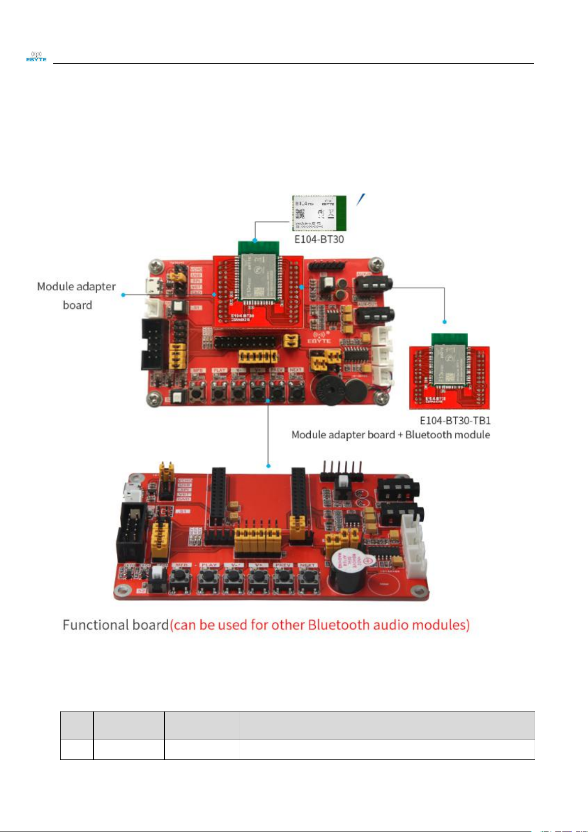
The E104-BT30-TB test board provides all the functional interfaces required for audio testing, making it easy to
quickly test the E104-BT30.
1.2 Parameters
Copyright ©2012–2019,Chengdu Ebyte Electronic Technology Co.,Ltd 1-2
Page 4

Chengdu Ebyte Electronic Technology Co.,Ltd E104-BT30-TB User Manual
2
Size
100 * 61.8 mm
Includes USB port
4
Power interface
USB/VBT/SPI
Selecting Power by Jumper Cap
5
Work Temp.
-40 ~ +85℃
Industrial grade
6
Work Humid.
10% ~ 90%
Relative humidity, non-condensing
7
Storage Temp.
-40 ~ +125℃
Industrial grade
2. Functions
2.1 Module introduction
LED Indicators:
LED 0: green
LED 1: red
LED 2: blue
Short press time: 300ms
Long press time: 1000ms
Function Sections:
A: Power supply circuit. We provide three power supply methods: USB, battery, and spi. Power can
be switched through the jumper at "Power Switch". Note here that only one power supply interface
can be used at a time. VCHG is the charging interface (reserved)
In this module, the S1 self-locking switch is the power switch and PWR is the power indicator
Copyright ©2012–2019,Chengdu Ebyte Electronic Technology Co.,Ltd 2-3
Page 5

Chengdu Ebyte Electronic Technology Co.,Ltd E104-BT30-TB User Manual
(green).
B: Adapter board interface, which can be used with our core board and adapter board.
C: This module is an audio input and output module.
S8: press the key, press to switch the input to the MIC interface, the default is the AUX interface
Mic: mic audio input.
Aux_in: aux input (reserved)
Aux_out: audio output interface (3.55mm headphones)
D: program download interface
E: LED indicating circuit, there are three states of LED combination state, unconnected, connected,
and discoverable state
Disconnected state: LED0 flashes twice quickly and then turns off, so reciprocate
Connected status: LED2 is always on
Discoverable status: LED0 and LED2 blink alternately
F: power amplifier circuit
The amplifier circuit is divided into the left channel and the right channel, which can be directly
connected to the speaker. Note that our amplifier can only push 3W power.
To use this external amplifier, you need to connect the jumper cap to the F plate as shown in the
figure.
G: Button circuit. There are five buttons as shown in the figure above. From left to right are MFB,
PLAY, V-, V +, PREV, NEXT.
MFB: It is a start button. Press and hold the power switch. After turning on the phone, it is still in the
pressed state to enter the discoverable state. If it is not pressed after turning on, it is in the
unconnected state. At this time, the paired mobile phone can directly connect to the module.
PLAY: For music playback, the pause button has the following states.
When the phone is connected, short press the PLAY button to play music and pause playback.
When connecting to a mobile phone, long press to disconnect the current connection and enter the
discoverable state. At this time, LED1 will blink once.
When connected to a mobile phone, when there is an incoming call, short press the PLAY button to
answer the call.
V-: This button is for volume reduction. It can be divided into long-press and short-press. Long-press
can continuously decrease the volume. Short-press decreases it a little.
V +: This button is for volume increase. There are long press and short press for the key. Long press
continuously increases the volume. Short press increases it a bit.
Note: The above two volume buttons cannot synchronize the volume of the mobile phone by default.
Copyright ©2012–2019,Chengdu Ebyte Electronic Technology Co.,Ltd 2-4
Page 6

Chengdu Ebyte Electronic Technology Co.,Ltd E104-BT30-TB User Manual
If you need to synchronize the volume of the mobile phone, you need to turn on the "volume
synchronization control" in the developer mode of the mobile phone. After it is turned on, please
clear the phone pairing and connect again.
PREV: This button is the previous button, which can control the phone to play the previous music
NEXT: This button is the next song button, which can control the phone to play the next music,
H: switch circuit
If it is currently turned off, press it again to turn it on. If it is turned on, press it again and then turn it
off.
Power on, MFB indicator (green) is always on.
Shut down and the MFB indicator (green) goes out.
TWS function:
TWS refers to the multi-connection mode, also called "pair-to-box". Two speakers can be configured
as a master and a slave. The master enters the initiating connection mode and the slave enters the
waiting connection mode.
Enter TWS host: PLAY button + PREV button, the blue light flashes quickly after pressing both
buttons simultaneously for 2 seconds
Enter the slave mode: PLAY button + NEXT button, the blue light flashes quickly after pressing both
buttons simultaneously for 2 seconds
When there is a master and a slave, wait for both parties to connect. After the host presses the PALY
button for a long time, the phone can connect to the host and use TWS normally.
End TWS connected: Press PREV and NEXT simultaneously for about two seconds to end TWS
connected mode.
3. Quick start
Step 1: Connect the USB power supply interface, and then switch the power supply mode to the USB power supply
Step 2: Use 3.55mm headphones to connect to AUX_OUT
Step 3: Press and hold the power button, then press and hold it until it is in a discoverable state
Step 4: Start Bluetooth on your phone, search for the module, and connect it
Step 5: Then the user can follow up the button function to test the Bluetooth module.
Copyright ©2012–2019,Chengdu Ebyte Electronic Technology Co.,Ltd 3-5
Page 7

Chengdu Ebyte Electronic Technology Co.,Ltd E104-BT30-TB User Manual
Version
Date
Description
Issued by
1.0
2020-3-23
Initial version
-
4. Disclaimer
This manual is as comprehensive and detailed as possible based on the existing materials. Our company reserves the right
to modify the manual without further notice.
This manual is only used as guide. All information in this manual does not constitute any expressed or implied warranty.
5. Revision history
About us
Sales hotline: 4000-330-990 Tel: 028-61399028
Support: support@cdebyte.com Website: www.ebyte.com
Address: Building B5, Mould Industrial Park, 199# Xiqu Ave, West High-tech Zone, Chengdu, 611731, Sichuan, China
Copyright ©2012–2019,Chengdu Ebyte Electronic Technology Co.,Ltd 3-6
 Loading...